EP3356171B1 - Procédé de contrôle de l'alimentation électrique d'injecteurs solénoïdes de carburant dans un véhicule automobile hybride - Google Patents
Procédé de contrôle de l'alimentation électrique d'injecteurs solénoïdes de carburant dans un véhicule automobile hybride Download PDFInfo
- Publication number
- EP3356171B1 EP3356171B1 EP16785249.0A EP16785249A EP3356171B1 EP 3356171 B1 EP3356171 B1 EP 3356171B1 EP 16785249 A EP16785249 A EP 16785249A EP 3356171 B1 EP3356171 B1 EP 3356171B1
- Authority
- EP
- European Patent Office
- Prior art keywords
- voltage
- internal combustion
- engine
- solenoid
- injectors
- Prior art date
- Legal status (The legal status is an assumption and is not a legal conclusion. Google has not performed a legal analysis and makes no representation as to the accuracy of the status listed.)
- Active
Links
Images
Classifications
-
- F—MECHANICAL ENGINEERING; LIGHTING; HEATING; WEAPONS; BLASTING
- F02—COMBUSTION ENGINES; HOT-GAS OR COMBUSTION-PRODUCT ENGINE PLANTS
- F02D—CONTROLLING COMBUSTION ENGINES
- F02D41/00—Electrical control of supply of combustible mixture or its constituents
- F02D41/20—Output circuits, e.g. for controlling currents in command coils
-
- B—PERFORMING OPERATIONS; TRANSPORTING
- B60—VEHICLES IN GENERAL
- B60K—ARRANGEMENT OR MOUNTING OF PROPULSION UNITS OR OF TRANSMISSIONS IN VEHICLES; ARRANGEMENT OR MOUNTING OF PLURAL DIVERSE PRIME-MOVERS IN VEHICLES; AUXILIARY DRIVES FOR VEHICLES; INSTRUMENTATION OR DASHBOARDS FOR VEHICLES; ARRANGEMENTS IN CONNECTION WITH COOLING, AIR INTAKE, GAS EXHAUST OR FUEL SUPPLY OF PROPULSION UNITS IN VEHICLES
- B60K6/00—Arrangement or mounting of plural diverse prime-movers for mutual or common propulsion, e.g. hybrid propulsion systems comprising electric motors and internal combustion engines
- B60K6/20—Arrangement or mounting of plural diverse prime-movers for mutual or common propulsion, e.g. hybrid propulsion systems comprising electric motors and internal combustion engines the prime-movers consisting of electric motors and internal combustion engines, e.g. HEVs
- B60K6/42—Arrangement or mounting of plural diverse prime-movers for mutual or common propulsion, e.g. hybrid propulsion systems comprising electric motors and internal combustion engines the prime-movers consisting of electric motors and internal combustion engines, e.g. HEVs characterised by the architecture of the hybrid electric vehicle
- B60K6/48—Parallel type
- B60K6/485—Motor-assist type
-
- B—PERFORMING OPERATIONS; TRANSPORTING
- B60—VEHICLES IN GENERAL
- B60L—PROPULSION OF ELECTRICALLY-PROPELLED VEHICLES; SUPPLYING ELECTRIC POWER FOR AUXILIARY EQUIPMENT OF ELECTRICALLY-PROPELLED VEHICLES; ELECTRODYNAMIC BRAKE SYSTEMS FOR VEHICLES IN GENERAL; MAGNETIC SUSPENSION OR LEVITATION FOR VEHICLES; MONITORING OPERATING VARIABLES OF ELECTRICALLY-PROPELLED VEHICLES; ELECTRIC SAFETY DEVICES FOR ELECTRICALLY-PROPELLED VEHICLES
- B60L58/00—Methods or circuit arrangements for monitoring or controlling batteries or fuel cells, specially adapted for electric vehicles
- B60L58/10—Methods or circuit arrangements for monitoring or controlling batteries or fuel cells, specially adapted for electric vehicles for monitoring or controlling batteries
- B60L58/18—Methods or circuit arrangements for monitoring or controlling batteries or fuel cells, specially adapted for electric vehicles for monitoring or controlling batteries of two or more battery modules
- B60L58/20—Methods or circuit arrangements for monitoring or controlling batteries or fuel cells, specially adapted for electric vehicles for monitoring or controlling batteries of two or more battery modules having different nominal voltages
-
- B—PERFORMING OPERATIONS; TRANSPORTING
- B60—VEHICLES IN GENERAL
- B60W—CONJOINT CONTROL OF VEHICLE SUB-UNITS OF DIFFERENT TYPE OR DIFFERENT FUNCTION; CONTROL SYSTEMS SPECIALLY ADAPTED FOR HYBRID VEHICLES; ROAD VEHICLE DRIVE CONTROL SYSTEMS FOR PURPOSES NOT RELATED TO THE CONTROL OF A PARTICULAR SUB-UNIT
- B60W10/00—Conjoint control of vehicle sub-units of different type or different function
- B60W10/04—Conjoint control of vehicle sub-units of different type or different function including control of propulsion units
- B60W10/06—Conjoint control of vehicle sub-units of different type or different function including control of propulsion units including control of combustion engines
-
- H—ELECTRICITY
- H01—ELECTRIC ELEMENTS
- H01F—MAGNETS; INDUCTANCES; TRANSFORMERS; SELECTION OF MATERIALS FOR THEIR MAGNETIC PROPERTIES
- H01F7/00—Magnets
- H01F7/06—Electromagnets; Actuators including electromagnets
- H01F7/08—Electromagnets; Actuators including electromagnets with armatures
- H01F7/18—Circuit arrangements for obtaining desired operating characteristics, e.g. for slow operation, for sequential energisation of windings, for high-speed energisation of windings
-
- H—ELECTRICITY
- H02—GENERATION; CONVERSION OR DISTRIBUTION OF ELECTRIC POWER
- H02J—ELECTRIC POWER NETWORKS; CIRCUIT ARRANGEMENTS OR SYSTEMS FOR SUPPLYING OR DISTRIBUTING ELECTRIC POWER; SYSTEMS FOR STORING ELECTRIC ENERGY
- H02J7/00—Circuit arrangements for charging or discharging batteries or for supplying loads from batteries
- H02J7/14—Circuit arrangements for charging or discharging batteries or for supplying loads from batteries for charging batteries from dynamo-electric generators driven at varying speed, e.g. on vehicle
-
- F—MECHANICAL ENGINEERING; LIGHTING; HEATING; WEAPONS; BLASTING
- F02—COMBUSTION ENGINES; HOT-GAS OR COMBUSTION-PRODUCT ENGINE PLANTS
- F02D—CONTROLLING COMBUSTION ENGINES
- F02D41/00—Electrical control of supply of combustible mixture or its constituents
- F02D41/20—Output circuits, e.g. for controlling currents in command coils
- F02D2041/2003—Output circuits, e.g. for controlling currents in command coils using means for creating a boost voltage, i.e. generation or use of a voltage higher than the battery voltage, e.g. to speed up injector opening
-
- F—MECHANICAL ENGINEERING; LIGHTING; HEATING; WEAPONS; BLASTING
- F02—COMBUSTION ENGINES; HOT-GAS OR COMBUSTION-PRODUCT ENGINE PLANTS
- F02D—CONTROLLING COMBUSTION ENGINES
- F02D2200/00—Input parameters for engine control
- F02D2200/02—Input parameters for engine control the parameters being related to the engine
- F02D2200/021—Engine temperature
-
- F—MECHANICAL ENGINEERING; LIGHTING; HEATING; WEAPONS; BLASTING
- F02—COMBUSTION ENGINES; HOT-GAS OR COMBUSTION-PRODUCT ENGINE PLANTS
- F02D—CONTROLLING COMBUSTION ENGINES
- F02D2200/00—Input parameters for engine control
- F02D2200/02—Input parameters for engine control the parameters being related to the engine
- F02D2200/06—Fuel or fuel supply system parameters
- F02D2200/0602—Fuel pressure
-
- F—MECHANICAL ENGINEERING; LIGHTING; HEATING; WEAPONS; BLASTING
- F02—COMBUSTION ENGINES; HOT-GAS OR COMBUSTION-PRODUCT ENGINE PLANTS
- F02D—CONTROLLING COMBUSTION ENGINES
- F02D2200/00—Input parameters for engine control
- F02D2200/02—Input parameters for engine control the parameters being related to the engine
- F02D2200/10—Parameters related to the engine output, e.g. engine torque or engine speed
- F02D2200/101—Engine speed
-
- F—MECHANICAL ENGINEERING; LIGHTING; HEATING; WEAPONS; BLASTING
- F02—COMBUSTION ENGINES; HOT-GAS OR COMBUSTION-PRODUCT ENGINE PLANTS
- F02D—CONTROLLING COMBUSTION ENGINES
- F02D2200/00—Input parameters for engine control
- F02D2200/50—Input parameters for engine control said parameters being related to the vehicle or its components
- F02D2200/503—Battery correction, i.e. corrections as a function of the state of the battery, its output or its type
-
- F—MECHANICAL ENGINEERING; LIGHTING; HEATING; WEAPONS; BLASTING
- F02—COMBUSTION ENGINES; HOT-GAS OR COMBUSTION-PRODUCT ENGINE PLANTS
- F02D—CONTROLLING COMBUSTION ENGINES
- F02D2400/00—Control systems adapted for specific engine types; Special features of engine control systems not otherwise provided for; Power supply, connectors or cabling for engine control systems
- F02D2400/16—Adaptation of engine control systems to a different battery voltages, e.g. for using high voltage batteries
-
- F—MECHANICAL ENGINEERING; LIGHTING; HEATING; WEAPONS; BLASTING
- F02—COMBUSTION ENGINES; HOT-GAS OR COMBUSTION-PRODUCT ENGINE PLANTS
- F02D—CONTROLLING COMBUSTION ENGINES
- F02D41/00—Electrical control of supply of combustible mixture or its constituents
- F02D41/30—Controlling fuel injection
- F02D41/38—Controlling fuel injection of the high pressure type
- F02D41/40—Controlling fuel injection of the high pressure type with means for controlling injection timing or duration
- F02D41/402—Multiple injections
-
- F—MECHANICAL ENGINEERING; LIGHTING; HEATING; WEAPONS; BLASTING
- F02—COMBUSTION ENGINES; HOT-GAS OR COMBUSTION-PRODUCT ENGINE PLANTS
- F02N—STARTING OF COMBUSTION ENGINES; STARTING AIDS FOR SUCH ENGINES, NOT OTHERWISE PROVIDED FOR
- F02N11/00—Starting of engines by means of electric motors
- F02N11/08—Circuits specially adapted for starting of engines
- F02N11/0862—Circuits specially adapted for starting of engines characterised by the electrical power supply means, e.g. battery
- F02N11/0866—Circuits specially adapted for starting of engines characterised by the electrical power supply means, e.g. battery comprising several power sources, e.g. battery and capacitor or two batteries
-
- H—ELECTRICITY
- H02—GENERATION; CONVERSION OR DISTRIBUTION OF ELECTRIC POWER
- H02J—ELECTRIC POWER NETWORKS; CIRCUIT ARRANGEMENTS OR SYSTEMS FOR SUPPLYING OR DISTRIBUTING ELECTRIC POWER; SYSTEMS FOR STORING ELECTRIC ENERGY
- H02J2105/00—Networks for supplying or distributing electric power characterised by their spatial reach or by the load
- H02J2105/30—Networks for supplying or distributing electric power characterised by their spatial reach or by the load the load networks being external to vehicles, i.e. exchanging power with vehicles
- H02J2105/33—Networks for supplying or distributing electric power characterised by their spatial reach or by the load the load networks being external to vehicles, i.e. exchanging power with vehicles exchanging power with road vehicles
- H02J2105/37—Networks for supplying or distributing electric power characterised by their spatial reach or by the load the load networks being external to vehicles, i.e. exchanging power with vehicles exchanging power with road vehicles exchanging power with electric vehicles [EV] or with hybrid electric vehicles [HEV]
-
- Y—GENERAL TAGGING OF NEW TECHNOLOGICAL DEVELOPMENTS; GENERAL TAGGING OF CROSS-SECTIONAL TECHNOLOGIES SPANNING OVER SEVERAL SECTIONS OF THE IPC; TECHNICAL SUBJECTS COVERED BY FORMER USPC CROSS-REFERENCE ART COLLECTIONS [XRACs] AND DIGESTS
- Y02—TECHNOLOGIES OR APPLICATIONS FOR MITIGATION OR ADAPTATION AGAINST CLIMATE CHANGE
- Y02T—CLIMATE CHANGE MITIGATION TECHNOLOGIES RELATED TO TRANSPORTATION
- Y02T10/00—Road transport of goods or passengers
- Y02T10/60—Other road transportation technologies with climate change mitigation effect
- Y02T10/62—Hybrid vehicles
-
- Y—GENERAL TAGGING OF NEW TECHNOLOGICAL DEVELOPMENTS; GENERAL TAGGING OF CROSS-SECTIONAL TECHNOLOGIES SPANNING OVER SEVERAL SECTIONS OF THE IPC; TECHNICAL SUBJECTS COVERED BY FORMER USPC CROSS-REFERENCE ART COLLECTIONS [XRACs] AND DIGESTS
- Y02—TECHNOLOGIES OR APPLICATIONS FOR MITIGATION OR ADAPTATION AGAINST CLIMATE CHANGE
- Y02T—CLIMATE CHANGE MITIGATION TECHNOLOGIES RELATED TO TRANSPORTATION
- Y02T10/00—Road transport of goods or passengers
- Y02T10/60—Other road transportation technologies with climate change mitigation effect
- Y02T10/70—Energy storage systems for electromobility, e.g. batteries
Definitions
- the subject of the present invention is a method for controlling the electrical supply of solenoid fuel injectors for a hybrid motor vehicle comprising on the one hand an internal combustion propulsion engine and on the other hand an electric motor.
- the invention finds very advantageous applications in that it makes it possible to dispense with the voltage-raising stages required in the embodiments of the prior art.
- said solenoid injectors are supplied with a voltage resulting from the direct voltage supplying the motor vehicle.
- this voltage is supplied by the battery of said motor vehicle and is 12 V.
- a DC voltage booster is then used which raises the voltage from 12 V to approximately 65 V.
- the injectors are controlled by means of a switching power supply, generally integrated into the engine control computer.
- This switching power supply is expensive in price but also in volume occupied. It is necessary to integrate large components into the engine control computer housing which are also the source of a large thermal power dissipated during their operation and it is necessary to design an electronic housing allowing all this energy to be evacuated heat without risk for the other components of the engine control computer.
- Requests DE 10 2008 043381 A1 And EP 1 876 340 A2 are examples of the prior art showing a hybrid engine whose power supply from the electric motor is used to power the injectors of the thermal engine.
- Requirement EP 2 083 159 A1 discloses a method for adapting the control parameters of the solenoid injectors from the power supply voltage, the engine speed, the fuel temperature and the injection pressure upstream of the solenoid injectors.
- the objective of the invention is to dispense with such a direct voltage booster in the context of hybrid vehicles equipped with an electric motor which have a second electrical network, supplied at a voltage higher than 12 V but nevertheless lower to the 65 V of a voltage booster.
- the illustrative example chosen, in no way limiting as to the scope of the invention, is that of a vehicle equipped with a device called "Mild-Hybrid" in technical jargon, that is to say a vehicle comprising a internal combustion propulsion engine and a non-directly propulsion electric motor, intended to assist the internal combustion propulsion engine.
- the electric motor is responsible for recovering energy from the deceleration phases of the vehicle in order to transform it into electricity stored in accumulator batteries. This energy is then returned to assist the internal combustion propulsion engine when necessary, during start-up or acceleration phases for example.
- the invention proposes a method for controlling the electrical supply of solenoid fuel injectors for a hybrid motor vehicle according to independent claim 1.
- the supply voltage of the electric motor typically a direct voltage of 48 V currently, can be sufficient to control solenoid fuel injectors by adapting the injection parameters to the voltage actually available.
- said voltage of 48 V is not constant and can decrease quite significantly below its nominal value depending on the operating phases of the electric motor. which more or less use on-board storage batteries responsible for delivering this voltage.
- the invention therefore wisely proposes to take this into account.
- the step of adapting the control parameters of the solenoid fuel injectors takes into account the engine speed of the internal combustion propulsion engine, the temperature of the internal combustion propulsion engine deduced from the temperature of the cooling liquid of the latter and the injection pressure upstream of the solenoid fuel injectors.
- the invention proposes to take into account not only the available DC voltage but also the engine speed of the internal combustion propulsion engine. Indeed, a high engine speed greatly reduces the possible fuel injection times.
- the temperature of the internal combustion propulsion engine typically that of the latter's cooling liquid, also influences the characteristics of said engine.
- the solenoid injector control parameters are the fuel injection time and the engine fuel injection start angle.
- the method according to the invention uses several hardware or software components and several actors to which reference will be made in the remainder of the description.
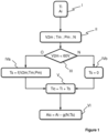
- FIG. 1 shows a flowchart implemented by a method of controlling the electrical supply of solenoid fuel injectors for a hybrid motor vehicle comprising on the one hand an internal combustion propulsion engine MCI and on the other hand an electric motor ME, said vehicle hybrid automobile being equipped with a first electrical network powered by a first direct voltage V1 and intended in particular to power the engine control of the internal combustion propulsion engine MCI and a second electrical network powered by a second direct voltage V2, said second voltage DC V2 being greater than the first DC voltage V1 and intended in particular to power the electric motor ME.
- the first direct voltage V1 is 12 V and comes from a lead acid battery and the second direct voltage V2 is 48 V and from a Lithium-ion accumulator battery.
- the parameters that the invention proposes to adapt are on the one hand the fuel injection time Ti and on the other hand the injection start angle Ai (step I).
- the invention therefore proposes to start from nominal settings stored in the memory of the engine control computer, for example, and to adapt them as a function of the voltage measured in real time.
- This value of the second direct voltage V2 measured in real time is called second available direct voltage V2m.
- step II we therefore measure the second available direct voltage V2m as well as the engine temperature Tm, the pressure Pm upstream of the solenoid injectors and the engine speed N.
- the engine temperature Tm is deduced from the temperature of the coolant of the internal combustion propulsion engine MCI which is usually a parameter monitored by the engine control computers and therefore does not require the addition of an additional sensor. This parameter influences the quality of combustion in the cylinders and can lead to correcting the selected injection parameters.
- the pressure Pm upstream of the solenoid injectors is also important to monitor because the flow rate of the solenoid injectors, and therefore the volume injected for a given solenoid injector opening time, can fluctuate. On modern direct injection engines, this pressure Pm is monitored and there is therefore no need to add a sensor to the existing ones here either.
- the engine speed N is also important because it influences the time available to carry out the injections. It is one of the basic quantities monitored in an engine control computer.
- step III an evaluation of the second available direct voltage V2m is made by comparing it to a threshold.
- a threshold In the example shown where the solenoid injectors have a nominal control voltage of 65 V, the threshold value is 60 V.
- the compensation time Ts is calculated taking into account the influencing factors measured previously, that is to say the engine temperature Tm, the pressure Pm upstream of the solenoid injectors and the engine speed N (step IVa).
- Step VI allows the calculation of the corrected injection start angle Aic, defined from the injection start angle Ai established in step I, reduced by a corrective factor which depends on the injection time.
- compensation Ts and engine speed N noted g (N; Ts).
- the two corrected parameters that is to say the corrected injection time Tic and the corrected injection start angle Aic are then used by the engine control computer of the internal combustion propulsion engine MCI in order to supervise the The electrical supply of the solenoid injectors, directly supplied by the second direct voltage V2.
- the invention does not apply as described to a scenario in which the second direct voltage V2 is much higher than the maximum voltage admissible by the solenoid injectors (case of electric motors supplied under a voltage of 400 V for example). In such a scenario it would be appropriate to provide a voltage reduction device if the second direct voltage V2 presents the risk of deterioration of the solenoid injectors.
Landscapes
- Engineering & Computer Science (AREA)
- Chemical & Material Sciences (AREA)
- Combustion & Propulsion (AREA)
- Mechanical Engineering (AREA)
- Power Engineering (AREA)
- Transportation (AREA)
- Physics & Mathematics (AREA)
- Electromagnetism (AREA)
- General Engineering & Computer Science (AREA)
- Life Sciences & Earth Sciences (AREA)
- Sustainable Development (AREA)
- Sustainable Energy (AREA)
- Electrical Control Of Air Or Fuel Supplied To Internal-Combustion Engine (AREA)
- Combined Controls Of Internal Combustion Engines (AREA)
- Control Of Vehicle Engines Or Engines For Specific Uses (AREA)
Description
- La présente invention a pour objet un procédé de contrôle de l'alimentation électrique d'injecteurs solénoïdes de carburant pour véhicule automobile hybride comportant d'une part un moteur propulsif à combustion interne et d'autre part un moteur électrique.
- L'invention trouve des applications très avantageuses en ce qu'elle permet de se dispenser des étages élévateurs de tension nécessités dans les modes de réalisation de l'art antérieur.
- Dans un véhicule automobile, hybride ou non, équipé d'un moteur propulsif à combustion interne dont les injecteurs de carburant sont de type solénoïdes, lesdits injecteurs solénoïdes sont alimentés sous une tension issue de la tension continue alimentant le véhicule automobile. Usuellement cette tension est fournie par la batterie dudit véhicule automobile et est de 12 V. Or une telle basse tension continue ne permet pas d'actionner les injecteurs de carburant solénoïdes. Il est alors utilisé un survolteur de tension continue qui élève la tension de 12 V à 65 V environ. Sur un moteur actuel à injection directe essence, la commande des injecteurs se fait ainsi au moyen d'une alimentation à découpage, généralement intégrée dans le calculateur de contrôle moteur.
- Cette alimentation à découpage est coûteuse en prix mais également en volume occupé. Il est nécessaire d'intégrer dans le boîtier du calculateur de contrôle moteur de gros composants qui sont en outre source d'une grande puissance thermique dissipée lors de leur fonctionnement et il y a lieu de concevoir un boîtier électronique permettant d'évacuer toute cette énergie calorifique sans risque pour les autres composants du calculateur de contrôle moteur.
- Les demandes
DE 10 2008 043381 A1 etEP 1 876 340 A2 sont des exemples de l'art antérieur montrant un moteur hybride dont l'alimentation du moteur électrique est utilisée pour alimenter les injecteurs du moteur thermique. - La demande
EP 2 083 159 A1 divulgue un procédé d'adaptation des paramètres de pilotage des injecteurs solénoïdes à partir de la tension de l'alimentation, du régime moteur, de la température du carburant et de la pression d'injection en amont des injecteurs solénoïdes. - L'objectif de l'invention est de se dispenser d'un tel survolteur de tension continue dans le cadre de véhicules hybrides dotés d'un moteur électrique qui possèdent un deuxième réseau électrique, alimenté à une tension plus élevée que 12 V mais néanmoins inférieure aux 65 V d'un survolteur de tension.
- L'exemple illustratif choisi, nullement limitatif quant à la portée de l'invention, est celui d'un véhicule équipé d'un dispositif appelé « Mild-Hybrid » dans le jargon technique, c'est-à-dire un véhicule comportant un moteur propulsif à combustion interne et un moteur électrique non directement propulsif, destiné à assister le moteur propulsif à combustion interne. Le moteur électrique est chargé de récupérer de l'énergie dans les phases de décélération du véhicule afin de la transformer en électricité stockée dans des batteries d'accumulateurs. Cette énergie est ensuite restituée en assistance du moteur propulsif à combustion interne en cas de besoin, lors des phases de démarrage ou d'accélération par exemple.
- Cet exemple de mode de réalisation n'exclut nullement que l'invention puisse être appliquée à un véhicule comportant deux moteurs propulsifs, également appelés « Full-Hybrid » en jargon technique.
- Pour cela l'invention propose un procédé de contrôle de l'alimentation électrique d'injecteurs solénoïdes de carburant pour véhicule automobile hybride selon la revendication indépendante 1.
- La Demanderesse a constaté que de manière surprenante et contrairement aux idées reçues, la tension d'alimentation du moteur électrique, typiquement une tension continue de 48 V actuellement, peut suffire à piloter des injecteurs solénoïdes de carburant en adaptant les paramètres d'injection à la tension réellement disponible. En effet, ladite tension de 48 V n'est pas constante et peut diminuer assez fortement en dessous de sa valeur nominale selon les phases de fonctionnement du moteur électrique qui font plus ou moins appel aux batteries d'accumulateurs embarquées et chargées de délivrer cette tension. L'invention propose donc judicieusement d'en tenir compte.
- Selon l'invention, l'étape d'adaptation des paramètres de pilotage des injecteurs solénoïdes de carburant tient compte du régime moteur du moteur propulsif à combustion interne, de la température du moteur propulsif à combustion interne déduite de la température du liquide de refroidissement de ce dernier et de la pression d'injection en amont des injecteurs solénoïdes de carburant. Ainsi, afin d'optimiser encore l'adaptation des paramètres de pilotage des injecteurs solénoïdes, l'invention propose de non seulement tenir compte de la tension continue disponible mais également du régime moteur du moteur propulsif à combustion interne. En effet, un régime moteur élevé diminue beaucoup les temps d'injection de carburant possibles. De même, la température du moteur propulsif à combustion interne, typiquement celle du liquide de refroidissement de ce dernier, influe également sur les caractéristiques dudit moteur. Enfin, il est également important de déterminer en temps réel la pression en carburant en amont des injecteurs solénoïdes de carburant car cette dernière grandeur conditionne le débit de carburant injectable et donc les temps d'ouverture des injecteurs solénoïdes de carburant.
- Dans un mode de réalisation, les paramètres de pilotage des injecteurs solénoïdes sont le temps d'injection de carburant et l'angle moteur de début d'injection de carburant.
- L'invention sera mieux comprise à la lecture de la description qui va suivre. Celle-ci est purement illustrative et doit être lue en regard des dessins annexés sur lesquels la
figure 1 montre un logigramme présentant les différentes étapes d'un procédé conforme à l'invention. - Il faut noter que la figure expose l'invention de manière détaillée pour mettre en oeuvre l'invention, ladite figure pouvant bien entendu servir à mieux définir l'invention le cas échéant.
- Dans la description, les mêmes références numériques désignent des éléments identiques ou fonctionnellement semblables.
- Le procédé selon l'invention met en oeuvre plusieurs composants matériels ou logiciels et plusieurs acteurs auxquels il sera fait référence dans la suite de la description.
- Dans la description, on prête des actions à des appareils ou à des programmes ; cela signifie que ces actions sont exécutées par un microprocesseur de cet appareil ou de l'appareil comportant le programme, ledit microprocesseur étant alors commandé par des codes instructions enregistrés dans une mémoire de l'appareil. Ces codes instructions permettent de mettre en oeuvre les moyens de l'appareil et donc de réaliser l'action entreprise.
- La
figure 1 montre un logigramme mis en oeuvre par un procédé de contrôle de l'alimentation électrique d'injecteurs solénoïdes de carburant pour véhicule automobile hybride comportant d'une part un moteur propulsif à combustion interne MCI et d'autre part un moteur électrique ME, ledit véhicule automobile hybride étant équipé d'un premier réseau électrique alimenté sous une première tension continue V1 et destinée notamment à alimenter le contrôle moteur du moteur propulsif à combustion interne MCI et d'un deuxième réseau électrique alimenté sous une deuxième tension continue V2, ladite deuxième tension continue V2 étant supérieure à la première tension continue V1 et destinée notamment à alimenter le moteur électrique ME. - A titre d'exemple illustratif, nullement limitatif en soi quant à la portée de l'invention, la première tension continue V1 est de 12 V et issue d'une batterie d'accumulateurs au plomb et la deuxième tension continue V2 est de 48 V et issue d'une batterie d'accumulateurs Lithium-ion.
- Les paramètres que l'invention se propose d'adapter sont d'une part le temps d'injection Ti de carburant et d'autre part l'angle de début d'injection Ai (étape I).
- En effet, si la tension est amenée à varier, puisque l'invention se propose de travailler avec la tension continue délivrée par la batterie d'accumulateurs alimentant le moteur électrique ME, il faut alors tenir compte du fait qu'un injecteur solénoïde de carburant va voir le temps de charge de son inductance varier avec la tension continue réellement appliquée. Pour un montage de l'art antérieur alimentant les injecteurs solénoïdes sous une tension connue et stabilisée cette prise en compte et adaptation ne s'impose pas.
- L'invention propose donc de partir de réglages nominaux stockés en mémoire du calculateur de contrôle moteur, par exemple, et de les adapter en fonction de la tension mesurée en temps réel. Cette valeur de la deuxième tension continue V2 mesurée en temps réel est appelée deuxième tension continue disponible V2m.
- A l'étape II, on mesure donc la deuxième tension continue disponible V2m ainsi que la température moteur Tm, la pression Pm en amont des injecteurs solénoïdes et le régime moteur N.
- La température moteur Tm est déduite de la température du liquide de refroidissement du moteur propulsif à combustion interne MCI qui est habituellement un paramètre suivi par les calculateurs de contrôle moteur et ne nécessite donc pas l'adjonction d'un capteur supplémentaire. Ce paramètre influe sur la qualité de la combustion dans les cylindres et peut amener à corriger les paramètres d'injection retenues.
- La pression Pm en amont des injecteurs solénoïdes est également importante à suivre car le débit des injecteurs solénoïdes, et donc le volume injecté pour un temps d'ouverture d'injecteur solénoïde donné, peut fluctuer. Sur les moteurs modernes à injection directe, cette pression Pm est suivie et il n'y a donc pas lieu ici non plus d'ajouter un capteur à ceux existants.
- Le régime moteur N est également important car il influe sur le temps disponible pour effectuer les injections. Il fait partie des grandeurs de base suivies dans un calculateur de contrôle moteur.
- Il est donc possible, en utilisant des grandeurs disponibles et suivies par le calculateur de contrôle moteur, d'avoir une vision précise des conditions de fonctionnement du moteur propulsif à combustion interne MCI peu de temps avant que l'injecteur solénoïde soit activé.
- A l'étape III une évaluation de la deuxième tension continue disponible V2m est faite en la comparant à un seuil. Dans l'exemple illustré où les injecteurs solénoïdes ont une tension nominale de commande de 65 V, la valeur seuil est de 60 V.
- Si la deuxième tension continue disponible V2m est supérieure ou égale à ce seuil de 60 V, alors aucune correction des paramètres d'injection n'est nécessaire. Le temps de compensation Ts est fixé à zéro à l'étape IVb, de telle sorte que le temps d'injection corrigé Tic défini à l'étape V par : Tic = Ti + Ts est identique au temps d'injection Ti initial.
- Si la deuxième tension continue disponible V2m est inférieure à ce seuil de 60 V, alors une correction des paramètres d'injection est nécessaire. Le temps de compensation Ts est calculé en tenant compte des facteurs influants mesurés précédemment, c'est-à-dire de la température moteur Tm, la pression Pm en amont des injecteurs solénoïdes et le régime moteur N (étape IVa). Ce facteur correctif qu'est le temps de compensation Ts est noté Ts = f(V2m ; Tm ; Pm). Le temps d'injection corrigé Tic défini à l'étape V par : Tic = Ti + Ts est alors établi.
- L'étape VI permet le calcul de l'angle de début d'injection corrigé Aic, défini à partir de l'angle de début d'injection Ai établi à l'étape I, diminué d'un facteur correctif qui dépend du temps de compensation Ts et du régime moteur N, noté g (N ; Ts).
- Ces facteurs correctifs peuvent être établis à partir de lois de calcul ou bien d'abaques établis pour chaque type de moteur durant des campagnes d'essais.
- Les deux paramètres corrigés, c'est-à-dire le temps d'injection corrigé Tic et l'angle de début d'injection corrigé Aic sont alors utilisés par le calculateur de contrôle moteur du moteur propulsif à combustion interne MCI afin de superviser l'alimentation électrique des injecteurs solénoïdes, directement alimentés par la deuxième tension continue V2.
- Dans une variante avantageuse, dans le cas d'un moteur propulsif à combustion interne MCI comportant des stratégies d'injections multiples de carburant par cylindre au sein d'un même cycle de fonctionnement, il est proposé d'introduire un test de cohérence afin de déterminer si le nombre d'injections multiples envisagé est possible ou non.
- Si le test de cohérence des paramètres de pilotage adaptés est satisfaisant, c'est-à-dire si la durée totale d'injection établie est compatible avec le temps imparti par les conditions de fonctionnement du moteur propulsif à combustion interne MCI, alors on maintient le nombre d'injections multiples prévues.
- Si le test de cohérence des paramètres de pilotage adaptés n'est pas satisfaisant, c'est-à-dire si la durée totale d'injection établie est supérieure au temps imparti par les conditions de fonctionnement du moteur propulsif à combustion interne MCI, alors on réduit le nombre d'injections multiples prévues, quitte à le restreindre à une seule injection dans la situation la plus défavorable.
- Il est à noter que l'invention peut aisément être adaptée à d'autres actuateurs au sein du véhicule automobile que les seuls injecteurs solénoïdes décrits précédemment, sans pour autant sortir de la portée de la présente invention.
- Il est également à noter que l'invention ne s'applique pas telle que décrite à un cas de figure dans lequel la deuxième tension continue V2 est très supérieure à la tension maximale admissible par les injecteurs solénoïdes (cas de moteurs électriques alimentés sous une tension de 400 V par exemple). Dans un tel cas de figure il y aurait lieu de prévoir un dispositif abaisseur de tension si la deuxième tension continue V2 présente le risque de détérioration des injecteurs solénoïdes.
Claims (2)
- Procédé de contrôle de l'alimentation électrique d'injecteurs solénoïdes de carburant pour véhicule automobile hybride comportant d'une part un moteur propulsif à combustion interne (MCI) et d'autre part un moteur électrique (ME), ledit véhicule automobile hybride étant équipé d'un premier réseau électrique alimenté sous une première tension continue (V1) et destinée notamment à alimenter un contrôle moteur du moteur propulsif à combustion interne (MCI) et d'un deuxième réseau électrique alimenté sous une deuxième tension continue (V2), ladite deuxième tension continue (V2) étant supérieure à la première tension continue (V1) et destinée notamment à alimenter le moteur électrique (ME), ledit procédé comporte les étapes suivantes :i. Connexion de la deuxième tension continue (V2) à l'alimentation électrique des injecteurs solénoïdes de carburant,ii. Lecture de la valeur de la deuxième tension continue (V2m), et lecture d'un régime moteur (N) du moteur propulsif à combustion interne (MCI), la lecture d'une température d'un liquide de refroidissement du moteur propulsif à combustion interne représentative d'une température (Tm) dudit moteur propulsif à combustion interne (MCI), et la lecture d'une pression d'injection (Pm) en amont des injecteurs solénoïdes de carburant,iii. Adaptation des paramètres de pilotage des injecteurs solénoïdes de carburant à partir de la valeur (V2m) lue à l'étape ii, d'un régime moteur (N) du moteur propulsif à combustion interne (MCI), de la température (Tm) du moteur propulsif à combustion interne (MCI) déduite de la température lue du liquide de refroidissement du moteur propulsif à combustion interne (MCI) et de la pression d'injection (Pm) en amont des injecteurs solénoïdes de carburant,iv. Pilotage des injecteurs solénoïdes de carburant au moyen de la deuxième tension continue (V2) avec :iv.a. aucune modification des paramètres de pilotage des injecteurs dans le cas où la valeur (V2m) est supérieure à une valeur seuil, etiv.b. modification d'au moins un des paramètres de pilotage des injecteurs dans le cas où la valeur (V2m) est inférieure à la valeur seuil.
- Procédé selon la revendication 1, dans lequel les paramètres de pilotage des injecteurs solénoïdes sont le temps d'injection (Ti) de carburant et l'angle moteur de début d'injection (Ai) de carburant.
Applications Claiming Priority (2)
| Application Number | Priority Date | Filing Date | Title |
|---|---|---|---|
| FR1559244A FR3041707B1 (fr) | 2015-09-30 | 2015-09-30 | Procede de controle de l'alimentation electrique d'injecteurs solenoides de carburant pour vehicule automobile hybride |
| PCT/FR2016/052478 WO2017055751A1 (fr) | 2015-09-30 | 2016-09-29 | Procédé de contrôle de l'alimentation électrique d'injecteurs solénoïdes de carburant dans un véhicule automobile hybride |
Publications (2)
| Publication Number | Publication Date |
|---|---|
| EP3356171A1 EP3356171A1 (fr) | 2018-08-08 |
| EP3356171B1 true EP3356171B1 (fr) | 2024-02-14 |
Family
ID=54783821
Family Applications (1)
| Application Number | Title | Priority Date | Filing Date |
|---|---|---|---|
| EP16785249.0A Active EP3356171B1 (fr) | 2015-09-30 | 2016-09-29 | Procédé de contrôle de l'alimentation électrique d'injecteurs solénoïdes de carburant dans un véhicule automobile hybride |
Country Status (6)
| Country | Link |
|---|---|
| US (1) | US11840975B2 (fr) |
| EP (1) | EP3356171B1 (fr) |
| CN (1) | CN108136888B (fr) |
| BR (1) | BR112018006495A2 (fr) |
| FR (1) | FR3041707B1 (fr) |
| WO (1) | WO2017055751A1 (fr) |
Families Citing this family (1)
| Publication number | Priority date | Publication date | Assignee | Title |
|---|---|---|---|---|
| FR3082160B1 (fr) * | 2018-06-12 | 2020-06-05 | Continental Automotive France | Systeme de commande du groupe motopropulseur d’un vehicule hybride avec gestion de la surpression dans la rampe d’injection |
Family Cites Families (13)
| Publication number | Priority date | Publication date | Assignee | Title |
|---|---|---|---|---|
| CN103061945B (zh) * | 2004-04-16 | 2015-07-29 | Avl里斯脱有限公司 | 控制机动车起动阶段的方法 |
| JP2008019852A (ja) * | 2006-06-14 | 2008-01-31 | Denso Corp | インジェクタ駆動装置及びインジェクタ駆動システム |
| US7448363B1 (en) * | 2007-07-02 | 2008-11-11 | Buell Motorcycle Company | Fuel delivery system and method of operation |
| EP2083159A1 (fr) * | 2008-01-28 | 2009-07-29 | GM Global Technology Operations, Inc. | Procédé pour la commande d'injecteurs de carburant actionnés par solénoïde de moteurs à combustion interne |
| DE102008043381A1 (de) * | 2008-11-03 | 2010-05-06 | Robert Bosch Gmbh | Vorrichtung mit einer Hochvoltstromversorgungsbaugruppe und einem Steuergerät |
| JP5029663B2 (ja) * | 2009-09-03 | 2012-09-19 | 株式会社デンソー | 燃料噴射制御装置 |
| EP2574764A1 (fr) * | 2011-09-30 | 2013-04-03 | Delphi Automotive Systems Luxembourg SA | Détermination de la vitesse d'une aiguille d'injecteur d'un injecteur de carburant à solénoïde et procédé de contrôle |
| DE102012213883B4 (de) * | 2012-08-06 | 2015-03-26 | Continental Automotive Gmbh | Gleichstellung des Stromverlaufs durch einen Kraftstoffinjektor für verschiedene Teileinspritzvorgänge einer Mehrfacheinspritzung |
| FR2996600B1 (fr) * | 2012-10-05 | 2014-11-21 | Continental Automotive France | Procede de gestion de la masse de combustible injectee dans un moteur |
| JP5772884B2 (ja) * | 2013-06-24 | 2015-09-02 | トヨタ自動車株式会社 | 燃料噴射弁駆動システム |
| JP5979104B2 (ja) * | 2013-09-04 | 2016-08-24 | 株式会社デンソー | 昇圧電源装置 |
| US9745914B2 (en) * | 2014-10-27 | 2017-08-29 | Toyota Jidosha Kabushiki Kaisha | Control apparatus for internal combustion engine |
| US20160208764A1 (en) * | 2015-01-20 | 2016-07-21 | General Electric Company | Systems and methods for estimating fuel quality in an engine |
-
2015
- 2015-09-30 FR FR1559244A patent/FR3041707B1/fr active Active
-
2016
- 2016-09-29 CN CN201680057093.9A patent/CN108136888B/zh active Active
- 2016-09-29 EP EP16785249.0A patent/EP3356171B1/fr active Active
- 2016-09-29 WO PCT/FR2016/052478 patent/WO2017055751A1/fr not_active Ceased
- 2016-09-29 BR BR112018006495-5A patent/BR112018006495A2/pt not_active Application Discontinuation
- 2016-09-29 US US15/762,762 patent/US11840975B2/en active Active
Also Published As
| Publication number | Publication date |
|---|---|
| CN108136888B (zh) | 2021-07-06 |
| EP3356171A1 (fr) | 2018-08-08 |
| US20190078526A1 (en) | 2019-03-14 |
| CN108136888A (zh) | 2018-06-08 |
| WO2017055751A1 (fr) | 2017-04-06 |
| FR3041707A1 (fr) | 2017-03-31 |
| BR112018006495A2 (pt) | 2018-10-09 |
| US11840975B2 (en) | 2023-12-12 |
| FR3041707B1 (fr) | 2019-09-13 |
Similar Documents
| Publication | Publication Date | Title |
|---|---|---|
| FR2882094A1 (fr) | Systeme de commande d'assistance de suralimentation | |
| FR3015571A1 (fr) | Procede et systeme de demarrage fiabilise de turbomachine | |
| FR2899939A1 (fr) | Dispositif de commande d'injection de carburant pour limiter le bruit de combustion d'un moteur. | |
| FR2869076A1 (fr) | Systeme d'injection de carburant a operation d'injection en chevauchement | |
| EP3356171B1 (fr) | Procédé de contrôle de l'alimentation électrique d'injecteurs solénoïdes de carburant dans un véhicule automobile hybride | |
| FR2775825A1 (fr) | Procede et dispositif pour commander un appareil utilisateur | |
| EP1994277A2 (fr) | Procede et systeme de commande d'une bougie de prechauffage, a alimentation a basse tension electrique, d'un melange air/carburant de moteur diesel | |
| WO2014170599A2 (fr) | Procédé de commande d'un compresseur électrique pour la suralimentation d'un moteur thermique | |
| EP2158672A2 (fr) | Machine electrique tournante et son procede de commande | |
| EP3304682B1 (fr) | Procédé de contrôle d'un ensemble batterie et alternateur pour un moteur de véhicule automobile | |
| EP2870614B1 (fr) | Circuit electrique pour l'excitation d'au moins un electro-aimant | |
| FR3013395A1 (fr) | Procede et systeme d'alimentation en gazole d'un vehicule automobile. | |
| FR2928418A1 (fr) | Dispositif et procede de commande de la reserve d'air dans des moteurs a combustion interne pilotes en fonction de la vitesse de rotation | |
| FR3043142B1 (fr) | Procede et dispositif de gestion de l'injection d'essence dans un cylindre d'un moteur a combustion d'un vehicule automobile | |
| FR2962495A1 (fr) | Procede de regulation de la pression d'un accumulateur haute pression de carburant d'un moteur a combustion interne | |
| FR2990579A1 (fr) | Procede de pilotage d'un generateur d'un vehicule automobile | |
| FR3009031A1 (fr) | Procede et dispositif de repolarisation d'un actionneur piezoelectrique d'un injecteur d'un moteur a combustion interne d'un vehicule ayant ete utilise | |
| FR3115567A1 (fr) | Optimisation d’une multi-injection | |
| FR2961967A1 (fr) | Procede de gestion de la tension d'alimentation d'un calculateur electronique de vehicule automobile | |
| WO2018130767A1 (fr) | Procédé de correction d'une durée d'injection de carburant dans un cylindre de moteur thermique de véhicule automobile | |
| FR2952967A1 (fr) | Procede de gestion d'une sonde a oxygene associee a un moteur a combustion interne | |
| FR3033463A1 (fr) | Calculateur et procede de gestion d'un equipement electrique d'un vehicule automobile | |
| WO2019238732A1 (fr) | Système de commande du groupe motopropulseur d'un véhicule hybride avec gestion de la surpression dans la rampe d'injection | |
| FR3108150A1 (fr) | Contrôle d'un injecteur piézo-électrique en lâché de pied accélérateur | |
| WO2019243503A1 (fr) | Procédé de régulation du rapport cyclique d'un signal permettant le contrôle en courant d'un module de conversion d'un convertisseur |
Legal Events
| Date | Code | Title | Description |
|---|---|---|---|
| STAA | Information on the status of an ep patent application or granted ep patent |
Free format text: STATUS: UNKNOWN |
|
| STAA | Information on the status of an ep patent application or granted ep patent |
Free format text: STATUS: THE INTERNATIONAL PUBLICATION HAS BEEN MADE |
|
| PUAI | Public reference made under article 153(3) epc to a published international application that has entered the european phase |
Free format text: ORIGINAL CODE: 0009012 |
|
| STAA | Information on the status of an ep patent application or granted ep patent |
Free format text: STATUS: REQUEST FOR EXAMINATION WAS MADE |
|
| 17P | Request for examination filed |
Effective date: 20180416 |
|
| AK | Designated contracting states |
Kind code of ref document: A1 Designated state(s): AL AT BE BG CH CY CZ DE DK EE ES FI FR GB GR HR HU IE IS IT LI LT LU LV MC MK MT NL NO PL PT RO RS SE SI SK SM TR |
|
| AX | Request for extension of the european patent |
Extension state: BA ME |
|
| DAV | Request for validation of the european patent (deleted) | ||
| DAX | Request for extension of the european patent (deleted) | ||
| RIC1 | Information provided on ipc code assigned before grant |
Ipc: H02J 7/14 20060101ALI20170419BHEP Ipc: B60K 6/485 20071001AFI20170419BHEP Ipc: F02N 11/08 20060101ALI20170419BHEP Ipc: F02D 41/20 20060101ALI20170419BHEP Ipc: B60W 10/06 20060101ALI20170419BHEP Ipc: F02D 41/40 20060101ALI20170419BHEP Ipc: H01F 7/18 20060101ALI20170419BHEP Ipc: B60L 11/18 20060101ALI20170419BHEP |
|
| RAP1 | Party data changed (applicant data changed or rights of an application transferred) |
Owner name: CONTINENTAL AUTOMOTIVE GMBH Owner name: CONTINENTAL AUTOMOTIVE FRANCE |
|
| RAP1 | Party data changed (applicant data changed or rights of an application transferred) |
Owner name: CONTINENTAL AUTOMOTIVE GMBH Owner name: CONTINENTAL AUTOMOTIVE FRANCE |
|
| RAP1 | Party data changed (applicant data changed or rights of an application transferred) |
Owner name: CONTINENTAL AUTOMOTIVE GMBH Owner name: CONTINENTAL AUTOMOTIVE FRANCE S.A.S |
|
| RAP1 | Party data changed (applicant data changed or rights of an application transferred) |
Owner name: VITESCO TECHNOLOGIES GMBH |
|
| STAA | Information on the status of an ep patent application or granted ep patent |
Free format text: STATUS: EXAMINATION IS IN PROGRESS |
|
| RAP3 | Party data changed (applicant data changed or rights of an application transferred) |
Owner name: VITESCO TECHNOLOGIES GMBH |
|
| 17Q | First examination report despatched |
Effective date: 20211116 |
|
| P01 | Opt-out of the competence of the unified patent court (upc) registered |
Effective date: 20230530 |
|
| REG | Reference to a national code |
Ref country code: DE Ipc: F02D0041200000 Ref legal event code: R079 Ref document number: 602016085782 Country of ref document: DE Free format text: PREVIOUS MAIN CLASS: B60K0006485000 |
|
| GRAP | Despatch of communication of intention to grant a patent |
Free format text: ORIGINAL CODE: EPIDOSNIGR1 |
|
| STAA | Information on the status of an ep patent application or granted ep patent |
Free format text: STATUS: GRANT OF PATENT IS INTENDED |
|
| RIC1 | Information provided on ipc code assigned before grant |
Ipc: F02N 11/08 20060101ALN20230906BHEP Ipc: F02D 41/40 20060101ALN20230906BHEP Ipc: B60L 58/20 20190101ALI20230906BHEP Ipc: H02J 7/14 20060101ALI20230906BHEP Ipc: H01F 7/18 20060101ALI20230906BHEP Ipc: F02D 41/20 20060101AFI20230906BHEP |
|
| INTG | Intention to grant announced |
Effective date: 20230926 |
|
| GRAS | Grant fee paid |
Free format text: ORIGINAL CODE: EPIDOSNIGR3 |
|
| GRAA | (expected) grant |
Free format text: ORIGINAL CODE: 0009210 |
|
| STAA | Information on the status of an ep patent application or granted ep patent |
Free format text: STATUS: THE PATENT HAS BEEN GRANTED |
|
| AK | Designated contracting states |
Kind code of ref document: B1 Designated state(s): AL AT BE BG CH CY CZ DE DK EE ES FI FR GB GR HR HU IE IS IT LI LT LU LV MC MK MT NL NO PL PT RO RS SE SI SK SM TR |
|
| REG | Reference to a national code |
Ref country code: GB Ref legal event code: FG4D Free format text: NOT ENGLISH |
|
| REG | Reference to a national code |
Ref country code: CH Ref legal event code: EP |
|
| REG | Reference to a national code |
Ref country code: DE Ref legal event code: R096 Ref document number: 602016085782 Country of ref document: DE |
|
| REG | Reference to a national code |
Ref country code: IE Ref legal event code: FG4D Free format text: LANGUAGE OF EP DOCUMENT: FRENCH |
|
| REG | Reference to a national code |
Ref country code: LT Ref legal event code: MG9D |
|
| REG | Reference to a national code |
Ref country code: NL Ref legal event code: MP Effective date: 20240214 |
|
| PG25 | Lapsed in a contracting state [announced via postgrant information from national office to epo] |
Ref country code: IS Free format text: LAPSE BECAUSE OF FAILURE TO SUBMIT A TRANSLATION OF THE DESCRIPTION OR TO PAY THE FEE WITHIN THE PRESCRIBED TIME-LIMIT Effective date: 20240614 |
|
| PG25 | Lapsed in a contracting state [announced via postgrant information from national office to epo] |
Ref country code: LT Free format text: LAPSE BECAUSE OF FAILURE TO SUBMIT A TRANSLATION OF THE DESCRIPTION OR TO PAY THE FEE WITHIN THE PRESCRIBED TIME-LIMIT Effective date: 20240214 |
|
| PG25 | Lapsed in a contracting state [announced via postgrant information from national office to epo] |
Ref country code: GR Free format text: LAPSE BECAUSE OF FAILURE TO SUBMIT A TRANSLATION OF THE DESCRIPTION OR TO PAY THE FEE WITHIN THE PRESCRIBED TIME-LIMIT Effective date: 20240515 |
|
| REG | Reference to a national code |
Ref country code: AT Ref legal event code: MK05 Ref document number: 1657197 Country of ref document: AT Kind code of ref document: T Effective date: 20240214 |
|
| PG25 | Lapsed in a contracting state [announced via postgrant information from national office to epo] |
Ref country code: RS Free format text: LAPSE BECAUSE OF FAILURE TO SUBMIT A TRANSLATION OF THE DESCRIPTION OR TO PAY THE FEE WITHIN THE PRESCRIBED TIME-LIMIT Effective date: 20240514 Ref country code: NL Free format text: LAPSE BECAUSE OF FAILURE TO SUBMIT A TRANSLATION OF THE DESCRIPTION OR TO PAY THE FEE WITHIN THE PRESCRIBED TIME-LIMIT Effective date: 20240214 Ref country code: HR Free format text: LAPSE BECAUSE OF FAILURE TO SUBMIT A TRANSLATION OF THE DESCRIPTION OR TO PAY THE FEE WITHIN THE PRESCRIBED TIME-LIMIT Effective date: 20240214 |
|
| PG25 | Lapsed in a contracting state [announced via postgrant information from national office to epo] |
Ref country code: ES Free format text: LAPSE BECAUSE OF FAILURE TO SUBMIT A TRANSLATION OF THE DESCRIPTION OR TO PAY THE FEE WITHIN THE PRESCRIBED TIME-LIMIT Effective date: 20240214 |
|
| PG25 | Lapsed in a contracting state [announced via postgrant information from national office to epo] |
Ref country code: AT Free format text: LAPSE BECAUSE OF FAILURE TO SUBMIT A TRANSLATION OF THE DESCRIPTION OR TO PAY THE FEE WITHIN THE PRESCRIBED TIME-LIMIT Effective date: 20240214 |
|
| PG25 | Lapsed in a contracting state [announced via postgrant information from national office to epo] |
Ref country code: RS Free format text: LAPSE BECAUSE OF FAILURE TO SUBMIT A TRANSLATION OF THE DESCRIPTION OR TO PAY THE FEE WITHIN THE PRESCRIBED TIME-LIMIT Effective date: 20240514 Ref country code: NO Free format text: LAPSE BECAUSE OF FAILURE TO SUBMIT A TRANSLATION OF THE DESCRIPTION OR TO PAY THE FEE WITHIN THE PRESCRIBED TIME-LIMIT Effective date: 20240514 Ref country code: NL Free format text: LAPSE BECAUSE OF FAILURE TO SUBMIT A TRANSLATION OF THE DESCRIPTION OR TO PAY THE FEE WITHIN THE PRESCRIBED TIME-LIMIT Effective date: 20240214 Ref country code: LT Free format text: LAPSE BECAUSE OF FAILURE TO SUBMIT A TRANSLATION OF THE DESCRIPTION OR TO PAY THE FEE WITHIN THE PRESCRIBED TIME-LIMIT Effective date: 20240214 Ref country code: IS Free format text: LAPSE BECAUSE OF FAILURE TO SUBMIT A TRANSLATION OF THE DESCRIPTION OR TO PAY THE FEE WITHIN THE PRESCRIBED TIME-LIMIT Effective date: 20240614 Ref country code: HR Free format text: LAPSE BECAUSE OF FAILURE TO SUBMIT A TRANSLATION OF THE DESCRIPTION OR TO PAY THE FEE WITHIN THE PRESCRIBED TIME-LIMIT Effective date: 20240214 Ref country code: GR Free format text: LAPSE BECAUSE OF FAILURE TO SUBMIT A TRANSLATION OF THE DESCRIPTION OR TO PAY THE FEE WITHIN THE PRESCRIBED TIME-LIMIT Effective date: 20240515 Ref country code: FI Free format text: LAPSE BECAUSE OF FAILURE TO SUBMIT A TRANSLATION OF THE DESCRIPTION OR TO PAY THE FEE WITHIN THE PRESCRIBED TIME-LIMIT Effective date: 20240214 Ref country code: ES Free format text: LAPSE BECAUSE OF FAILURE TO SUBMIT A TRANSLATION OF THE DESCRIPTION OR TO PAY THE FEE WITHIN THE PRESCRIBED TIME-LIMIT Effective date: 20240214 Ref country code: BG Free format text: LAPSE BECAUSE OF FAILURE TO SUBMIT A TRANSLATION OF THE DESCRIPTION OR TO PAY THE FEE WITHIN THE PRESCRIBED TIME-LIMIT Effective date: 20240214 Ref country code: AT Free format text: LAPSE BECAUSE OF FAILURE TO SUBMIT A TRANSLATION OF THE DESCRIPTION OR TO PAY THE FEE WITHIN THE PRESCRIBED TIME-LIMIT Effective date: 20240214 |
|
| PG25 | Lapsed in a contracting state [announced via postgrant information from national office to epo] |
Ref country code: PL Free format text: LAPSE BECAUSE OF FAILURE TO SUBMIT A TRANSLATION OF THE DESCRIPTION OR TO PAY THE FEE WITHIN THE PRESCRIBED TIME-LIMIT Effective date: 20240214 Ref country code: PT Free format text: LAPSE BECAUSE OF FAILURE TO SUBMIT A TRANSLATION OF THE DESCRIPTION OR TO PAY THE FEE WITHIN THE PRESCRIBED TIME-LIMIT Effective date: 20240614 |
|
| PG25 | Lapsed in a contracting state [announced via postgrant information from national office to epo] |
Ref country code: SE Free format text: LAPSE BECAUSE OF FAILURE TO SUBMIT A TRANSLATION OF THE DESCRIPTION OR TO PAY THE FEE WITHIN THE PRESCRIBED TIME-LIMIT Effective date: 20240214 Ref country code: PT Free format text: LAPSE BECAUSE OF FAILURE TO SUBMIT A TRANSLATION OF THE DESCRIPTION OR TO PAY THE FEE WITHIN THE PRESCRIBED TIME-LIMIT Effective date: 20240614 Ref country code: PL Free format text: LAPSE BECAUSE OF FAILURE TO SUBMIT A TRANSLATION OF THE DESCRIPTION OR TO PAY THE FEE WITHIN THE PRESCRIBED TIME-LIMIT Effective date: 20240214 Ref country code: LV Free format text: LAPSE BECAUSE OF FAILURE TO SUBMIT A TRANSLATION OF THE DESCRIPTION OR TO PAY THE FEE WITHIN THE PRESCRIBED TIME-LIMIT Effective date: 20240214 |
|
| PG25 | Lapsed in a contracting state [announced via postgrant information from national office to epo] |
Ref country code: DK Free format text: LAPSE BECAUSE OF FAILURE TO SUBMIT A TRANSLATION OF THE DESCRIPTION OR TO PAY THE FEE WITHIN THE PRESCRIBED TIME-LIMIT Effective date: 20240214 |
|
| PG25 | Lapsed in a contracting state [announced via postgrant information from national office to epo] |
Ref country code: SM Free format text: LAPSE BECAUSE OF FAILURE TO SUBMIT A TRANSLATION OF THE DESCRIPTION OR TO PAY THE FEE WITHIN THE PRESCRIBED TIME-LIMIT Effective date: 20240214 |
|
| PG25 | Lapsed in a contracting state [announced via postgrant information from national office to epo] |
Ref country code: EE Free format text: LAPSE BECAUSE OF FAILURE TO SUBMIT A TRANSLATION OF THE DESCRIPTION OR TO PAY THE FEE WITHIN THE PRESCRIBED TIME-LIMIT Effective date: 20240214 Ref country code: CZ Free format text: LAPSE BECAUSE OF FAILURE TO SUBMIT A TRANSLATION OF THE DESCRIPTION OR TO PAY THE FEE WITHIN THE PRESCRIBED TIME-LIMIT Effective date: 20240214 |
|
| PG25 | Lapsed in a contracting state [announced via postgrant information from national office to epo] |
Ref country code: SK Free format text: LAPSE BECAUSE OF FAILURE TO SUBMIT A TRANSLATION OF THE DESCRIPTION OR TO PAY THE FEE WITHIN THE PRESCRIBED TIME-LIMIT Effective date: 20240214 |
|
| PG25 | Lapsed in a contracting state [announced via postgrant information from national office to epo] |
Ref country code: SM Free format text: LAPSE BECAUSE OF FAILURE TO SUBMIT A TRANSLATION OF THE DESCRIPTION OR TO PAY THE FEE WITHIN THE PRESCRIBED TIME-LIMIT Effective date: 20240214 Ref country code: SK Free format text: LAPSE BECAUSE OF FAILURE TO SUBMIT A TRANSLATION OF THE DESCRIPTION OR TO PAY THE FEE WITHIN THE PRESCRIBED TIME-LIMIT Effective date: 20240214 Ref country code: RO Free format text: LAPSE BECAUSE OF FAILURE TO SUBMIT A TRANSLATION OF THE DESCRIPTION OR TO PAY THE FEE WITHIN THE PRESCRIBED TIME-LIMIT Effective date: 20240214 Ref country code: EE Free format text: LAPSE BECAUSE OF FAILURE TO SUBMIT A TRANSLATION OF THE DESCRIPTION OR TO PAY THE FEE WITHIN THE PRESCRIBED TIME-LIMIT Effective date: 20240214 Ref country code: DK Free format text: LAPSE BECAUSE OF FAILURE TO SUBMIT A TRANSLATION OF THE DESCRIPTION OR TO PAY THE FEE WITHIN THE PRESCRIBED TIME-LIMIT Effective date: 20240214 Ref country code: CZ Free format text: LAPSE BECAUSE OF FAILURE TO SUBMIT A TRANSLATION OF THE DESCRIPTION OR TO PAY THE FEE WITHIN THE PRESCRIBED TIME-LIMIT Effective date: 20240214 |
|
| REG | Reference to a national code |
Ref country code: DE Ref legal event code: R097 Ref document number: 602016085782 Country of ref document: DE |
|
| PG25 | Lapsed in a contracting state [announced via postgrant information from national office to epo] |
Ref country code: IT Free format text: LAPSE BECAUSE OF FAILURE TO SUBMIT A TRANSLATION OF THE DESCRIPTION OR TO PAY THE FEE WITHIN THE PRESCRIBED TIME-LIMIT Effective date: 20240214 |
|
| PLBE | No opposition filed within time limit |
Free format text: ORIGINAL CODE: 0009261 |
|
| STAA | Information on the status of an ep patent application or granted ep patent |
Free format text: STATUS: NO OPPOSITION FILED WITHIN TIME LIMIT |
|
| PG25 | Lapsed in a contracting state [announced via postgrant information from national office to epo] |
Ref country code: IT Free format text: LAPSE BECAUSE OF FAILURE TO SUBMIT A TRANSLATION OF THE DESCRIPTION OR TO PAY THE FEE WITHIN THE PRESCRIBED TIME-LIMIT Effective date: 20240214 |
|
| 26N | No opposition filed |
Effective date: 20241115 |
|
| REG | Reference to a national code |
Ref country code: DE Ref legal event code: R119 Ref document number: 602016085782 Country of ref document: DE |
|
| PG25 | Lapsed in a contracting state [announced via postgrant information from national office to epo] |
Ref country code: MC Free format text: LAPSE BECAUSE OF FAILURE TO SUBMIT A TRANSLATION OF THE DESCRIPTION OR TO PAY THE FEE WITHIN THE PRESCRIBED TIME-LIMIT Effective date: 20240214 Ref country code: SI Free format text: LAPSE BECAUSE OF FAILURE TO SUBMIT A TRANSLATION OF THE DESCRIPTION OR TO PAY THE FEE WITHIN THE PRESCRIBED TIME-LIMIT Effective date: 20240214 |
|
| REG | Reference to a national code |
Ref country code: CH Ref legal event code: PL |
|
| PG25 | Lapsed in a contracting state [announced via postgrant information from national office to epo] |
Ref country code: LU Free format text: LAPSE BECAUSE OF NON-PAYMENT OF DUE FEES Effective date: 20240929 |
|
| GBPC | Gb: european patent ceased through non-payment of renewal fee |
Effective date: 20240929 |
|
| PG25 | Lapsed in a contracting state [announced via postgrant information from national office to epo] |
Ref country code: DE Free format text: LAPSE BECAUSE OF NON-PAYMENT OF DUE FEES Effective date: 20250401 |
|
| PG25 | Lapsed in a contracting state [announced via postgrant information from national office to epo] |
Ref country code: GB Free format text: LAPSE BECAUSE OF NON-PAYMENT OF DUE FEES Effective date: 20240929 |
|
| REG | Reference to a national code |
Ref country code: BE Ref legal event code: MM Effective date: 20240930 |
|
| PG25 | Lapsed in a contracting state [announced via postgrant information from national office to epo] |
Ref country code: BE Free format text: LAPSE BECAUSE OF NON-PAYMENT OF DUE FEES Effective date: 20240930 |
|
| PG25 | Lapsed in a contracting state [announced via postgrant information from national office to epo] |
Ref country code: CH Free format text: LAPSE BECAUSE OF NON-PAYMENT OF DUE FEES Effective date: 20240930 |
|
| PG25 | Lapsed in a contracting state [announced via postgrant information from national office to epo] |
Ref country code: IE Free format text: LAPSE BECAUSE OF NON-PAYMENT OF DUE FEES Effective date: 20240929 |
|
| PGFP | Annual fee paid to national office [announced via postgrant information from national office to epo] |
Ref country code: FR Payment date: 20250922 Year of fee payment: 10 |
|
| PG25 | Lapsed in a contracting state [announced via postgrant information from national office to epo] |
Ref country code: CY Free format text: LAPSE BECAUSE OF FAILURE TO SUBMIT A TRANSLATION OF THE DESCRIPTION OR TO PAY THE FEE WITHIN THE PRESCRIBED TIME-LIMIT; INVALID AB INITIO Effective date: 20160929 |
|
| PG25 | Lapsed in a contracting state [announced via postgrant information from national office to epo] |
Ref country code: HU Free format text: LAPSE BECAUSE OF FAILURE TO SUBMIT A TRANSLATION OF THE DESCRIPTION OR TO PAY THE FEE WITHIN THE PRESCRIBED TIME-LIMIT; INVALID AB INITIO Effective date: 20160929 |