EP3356586B1 - Vorrichtung und verfahren zum erfassen des endes eines kettfadens oder eines bandes auf einer textilwebmaschine - Google Patents
Vorrichtung und verfahren zum erfassen des endes eines kettfadens oder eines bandes auf einer textilwebmaschine Download PDFInfo
- Publication number
- EP3356586B1 EP3356586B1 EP16788215.8A EP16788215A EP3356586B1 EP 3356586 B1 EP3356586 B1 EP 3356586B1 EP 16788215 A EP16788215 A EP 16788215A EP 3356586 B1 EP3356586 B1 EP 3356586B1
- Authority
- EP
- European Patent Office
- Prior art keywords
- yarn
- drop wire
- warp yarn
- warp
- breakage
- Prior art date
- Legal status (The legal status is an assumption and is not a legal conclusion. Google has not performed a legal analysis and makes no representation as to the accuracy of the status listed.)
- Active
Links
Images




Classifications
-
- D—TEXTILES; PAPER
- D03—WEAVING
- D03D—WOVEN FABRICS; METHODS OF WEAVING; LOOMS
- D03D51/00—Driving, starting, or stopping arrangements; Automatic stop motions
- D03D51/18—Automatic stop motions
- D03D51/20—Warp stop motions
- D03D51/28—Warp stop motions electrical
- D03D51/30—Warp stop motions electrical wherein droppers are suspended on individual warp threads or small groups of threads
Definitions
- Device of the invention relates to weaving machines, containing warp and weft yarns/tapes for fabric weaving on circular weaving machines, more precisely, sensing end of warp yarn/tape during fabric production.
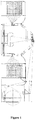
- the circular weaving loom or machine is designed to weave endless tubular or flat fabric using PP, HDPE, LLDPE yarn/tape or other blends of polyolefin ( Figure1 ).
- the warp yarns/tapes are fed to the weaving machine-from more than one creel via rollers. This ensures uniform warp tension, excellent fabric quality, and trouble-free handling ( Figures 2 & 3 ).
- the loose yarn/tape may possibly entangle with other nearby yarns/tapes coming from adjacent bobbins thereby damaging section of the running fabric.
- one of the drawbacks of the existing systems is its requirement to regularly monitor bobbin exhaustion by operator.
- another drawback of the existing systems is that when the ends of the warp are noticed, the machine needs to be stopped immediately such that the ends of the warp tapes are not allowed to reach reed ring section of the weaving machine.
- Drop wire systems consist of a gravity-controlled 'drop wire' made of metals such as stainless steel through which the tape used for fabric making passes.
- yarn/tape loses it tension which causes it to slag causing drop wire to fall down.
- operator observes slag in yarn/tape and stops the machine to change the empty or semi filled tube with new bobbin.
- one of the objects of the present invention is to provide an automated system for sensing warp end.
- Another object of the invention is to provide an automated system for detecting warp end which will work robustly in dusty environment.
- a further object of the invention is to provide an improved drop wire for the purpose of detection of warp end.
- Another object of the present invention is to provide a system that reduces the wastage of weaved fabric and machine downtime.
- the invention discloses a device for sensing an end of a warp yarn or tape on a fabric weaving loom according to claim 1.
- the device is so designed that upon detection of a yarn end (due to yarn breakage or due to the yarn package running out of yarn) by a yarn detection means that is also a part of the device, an electric circuit is completed and a notification is sent to the loom operator.
- the invention is particularly suitable in dusty environment in which CWMs typically operate.
- the invention utilizes an improved drop wire (6) which maintains its normal operating position by hanging by the running yarn that passes through a loop provided at one end of the drop wire.
- the drop wire is provided with an electrically conducting first element having a spatially curved external surface. Breakage of the running yarn causes loss of tension in the yarn, causing the drop wire to lose its elevation rapidly.
- the device of the invention also incorporates a set of electrically conducting second elements having a curved internal surface. Upon the loss of elevation, the first and second elements come in electrical contact with each other, thereby completing an electric circuit and consequently causing a signal to be sent to the operator of the loom indicating yarn breakage.
- Drop wires (6) are provided on every individual warp yarn/tape which is fed to the central reed ring section.
- Woven fabric for use in making bags for storing materials such as grains, cement, etc. is made from yarn/tape of PP, HDPE, LLDPE or other blends of polyolefin.
- a circular weaving machine/loom that makes tubular fabric for making such bags deploys a number of bobbins.
- Figure 2 shows the typical yarn travel path in a CWM.
- the device disclosed in the invention allows detection of ends of a broken yarn/tape so that the CWM may be stopped in order and a signal is sent to the operator on duty to avoid entanglement of the broken yarn/tape with other yarns/tapes operational on the CWM.
- the key purpose of the device of the invention is to detect the breakage or end of a running yarn and inform the loom operator of its occurrence. This is achieved by providing the following three key elements in the device: a means to detect the yarn breakage, an electric circuit, and a notification means.
- the CWMs operate in an environment where a substantial amount of particulate matter (dust) is generated as a result of loom operation. These particles settle on any available surface in the vicinity of the loom. The settled dust which is electrically non-conductive has the potential to hamper the loom operations. In the case of systems to detect yarn ends, where electric circuits are employed, the smooth working of such circuits may be hampered by such dust.
- One of the key aspects of the device of the invention is that it works effectively regardless of the dusty environments within which they are deployed.
- the present invention discloses a device for sensing end of warp yarn or tapes on an automated fabric weaving loom and notifying the instance of yarn breakage to the operator. It comprises a yarn end detection means to detect the breakage of or a slack in running yarn, an electric circuit, and a notification means to notify breakage of or slack in yarn.
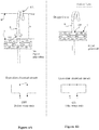
- the yarn end detection means comprises an improved weighted drop wire (6) ( Figures 4A and 6A ) with an eye (6A) at its one end through which the running warp yarn/tape (9) passes, and which is held in substantially upheld position by the tension in the running yarn (9).
- An electrically conducting first element (6B) is attached fixedly to the drop at a predetermined distance 'h' ( Figure 4A ) from the eye (6A).
- the drop of the drop wire (6) from its normal operating position is substantial and irrecoverable.
- the drop wire (6) drops vertically by a substantial distance from its normal operating position on substantial loss of tension in the running yarn (6) - sensing of the irrecoverable drop of the drop wire (6) represents yarn end detection.
- a pair of electrically conducting second elements (7) (see Figures 5A/5B ) is provided as a part of the electric circuit that is referred to earlier.
- the components of the electric circuit are the first elements (6B), second elements (7), an electronic circuit (8) that electrically connects two second elements (7) of any pair of the second elements (7) at one end of the second elements (7), and a source of electric power. It further comprises an electric switch or a loop that is yarn-dust-proof. During the normal working operation of the loom, the electric switch/loop remains 'open'. The device is so designed that upon detection of a yarn breakage or a yarn end, the electric switch/loop closes effectively thereby completing the electric circuit - regardless of the presence of dusty environment. Upon closure of the electric circuit, an alarm is raised and a signal is sent to the operator indicating the yarn breakage.
- the drop wire (6) supports a first element that has an electrically conducting outer surface (6C).
- the outer surface (6C) of the first element (6B) is spatially curved ( Figure 6A ), preferably substantially in the form of a cone of any type.
- the outer surface (6C) may have serrations that run substantially longitudinally.
- the yarn-dust-proof electric switch/loop comprises a pair of electrically conducting second elements (7).
- the second elements (7) are provided with inner curved shaped surfaces (also termed as inner surfaces or inner shaped surfaces) (7B) with a shape that corresponds to the outer surface (6C) of the first elements (6B).
- the term 'corresponds' mentioned above refers to the correspondence between the outer surface (6C) of the first element (6B) and the shaped inner surface (7B) of the second element (7), and is to be understood in the context of electrical connection.
- the outer surface (6C) of the first element (6B) and the corresponding inner surface (7B or 7C) on the second element do not have to be 'exactly matching' - that is they do not need to be in full contact with each other.
- correspondence it is meant that there simply needs to be sufficient contact so that the electric switch/loop is closed effectively.
- the dust tends to settle on surfaces that are, among other characteristics, devoid of geometric features such as points and sharp edges.
- the inner surfaces (7B) of the second elements (7) are provided with points and/or sharp edges. Some of these are illustrated in Figure 7 .
- the second elements (7) are in the form of a strip or a plate on which are provided the inner curved shaped surfaces (7B).
- these plates When positioned across from each other, these plates, with the inner curved shaped surfaces (7B) facing the inner curved shaped surfaces (7B) of the other second element (7) from the pair of second elements, they form receptors into which the first elements (6B) fall when the drop wire (6) loses its elevation substantially.
- the gap (7A) is so designed that the drop wire (6) passes through it in its normal working position without closing the electric loop.
- the curve of the outer surface (6C) of the first element (6B) may of any shape, however it should be such that when the drop wire (6) drops from its normal working position, the first element (6B)------owing to the curvature of its outer surface (6C)------goes into the gap (7A) between the inner shaped curved surfaces (7B) of the two parts of the second elements (7) easily.
- the curvature of the outer surface (6C) should be of such shape that upon resumption of the tension in the yarn, when the drop wire (6) is pulled up back to its own normal working position due to the tension in the yarn, this upward movement of the drop wire (6) is carried out unhindered.
- the inner curved shaped surfaces (7B) of the second elements (7) may be made of a single surface (7C) ( Figure 6D ) or multiple sub-surfaces (7D) ( Figures 6B/6C ).
- the junctions between any two sub-surfaces (7D) are preferably in the form of a point (7E) or an edge (7F) (see Figure 7 ) that is preferably sharp.
- Formation of points or sharp edges (7E and/or 7F) is important in order to not allow dust to settle on at least some part of the curved shaped inner surfaces (7B).
- the vertical distance 'h' ( Figure 4A ) at which the first element (6B) is located from the running yarn (9) that supports a particular drop wire (6) depends on the overall configuration of the system of yarns. The distance should be such that upon yarn breakage detection, the circuit is closed within a reasonably short time period. The distance should also be such that there is no false alarm raised in situations where there is temporary loss of tension. However, there may be exceptional circumstances, where the loss of tension is due to abnormal or unexpected slack in an unbroken running yarn, where the drop wire (6) may drop sufficiently so that the circuit closes.
- One feature of the present invention is its ability to distinguish between temporary slack in the warp and permanent breakage in the yarn/tape (9).
- the yarn (9) resumes its normal operation once the slack is eliminated by the ongoing movement of the yarn (9). This may take a duration as small as 0.1 seconds and up to 2 seconds. Under such circumstances, it would be undesirable if the CWM shuts down simply because there was a circuit closure (which is typically indicative of yarn end detection).
- the device is provided with time monitoring facility. Time from any given closure of circuit is monitored and noted. In the case where there's no opening up of the circuit following from a circuit closure event within a predetermined period, it is indicative of a situation involving a yarn end or other undesirable event that suggests that it would be potentially harmful to allow the CWM to continue operation without intervention. In such situation the CWM is made to shut down and a notification signal is sent. The signal may be sent to a monitor. In the case where there's opening of the circuit within the predetermined period, no notification would be sent, however, the CWM will be permitted to continue operation.
- the inbuilt intelligent module eliminates possibility of any faulty alarm generation for temporary loosening in yarn/tape (9), and more importantly the consequent shutting down of the CWM.
- Temporary slack of warp yarn/tape (9) is very common in weaving machines which on account of false alarms consumes significant amount of resources in terms of time and manpower utilization as machine get down for this time period, which is always desirable to avoid under any circumstances.
Landscapes
- Engineering & Computer Science (AREA)
- Textile Engineering (AREA)
- Looms (AREA)
Claims (9)
- Gerät bzw. Vorrichtung zum Erkennen von Bruch von oder einem Ende von Kettgarnen (9) oder Bändern an einer Gewebe- bzw. Stoffwebmaschine, wobei die Vorrichtung umfasst:ein Garnendeerkennungsmittel, umfassend:- eine Lamelle (6) mit einer Öffnung (6A) für den Durchgang von dem Kettgarn (9) und wobei die Lamelle (6) durch Spannung auf dem Kettgarn (9) in ihrer normalen Betriebsposition gehalten wird; und- ein erstes Element (6B), das auf die Lamelle (6) montiert ist und eine elektrisch leitende äußere Fläche bzw. Außenfläche (6C) aufweist, wobei die Lamelle (6) und das erste Element (6B) entsprechend jeden Kettgarns bereitgestellt werden (9);ein elektrischer Stromkreis, von dem das Garnendeerkennungsmittel einen Teil bildet,und ein Benachrichtigungsmittel, um den Bruch oder das Ende des Kettgarns (9) anzuzeigen,wobei der elektrische Stromkreis ein Paar von zweiten Elementen (7) umfasst, zwischen denen eine physische Lücke (7A) besteht;wobei jedes der zweiten Elemente (7) eine elektrisch leitende, innere, kurvenförmige Fläche (7B) aufweist, die der Lamelle (6) entspricht,wobei die inneren, kurvenförmigen Flächen (7B) mit einer Form versehen sind, die der der äußeren Fläche bzw. Außenfläche (6C) des ersten Elements (6B) entspricht, undwobei, anschließend an das Fallen der Lamelle (6) von ihrer normalen Betriebsposition aufgrund beträchtlichen Spannungsverlusts in dem Kettgarn (9) der elektrische Stromkreis dadurch geschlossen wird, dass die elektrisch leitende Außenfläche (6C) des ersten Elements (6B) mit den elektrisch leitenden, inneren, kurvenförmigen Flächen (7B) der zweiten Elemente (7) in Kontakt kommt und dadurch das Benachrichtigungsmittel für eine Erzeugung eines Benachrichtigungssignals für Garn-/Bandbruch oder -ende auslöst.
- Gerät bzw. Vorrichtung nach Anspruch 1, dadurch gekennzeichnet, dass die elektrisch leitende äußere Fläche bzw. Außenfläche (6C) räumlich gekrümmt ist und die innere, kurvenförmige Fläche (7B) eine Anzahl von unteren Flächen (7D) aufweist, und wobei die Grenzflächen zwischen einzelnen unteren Flächen (7D) Kanten oder Spitzen sind, wobei besagte Kanten scharfkantig sind.
- Gerät bzw. Vorrichtung nach einem der Ansprüche 1 und 2, dadurch gekennzeichnet, dass das Benachrichtigungssignal ein Audiosignal, ein visuelles Signal oder audiovisuelles Signal ist, oder ein Signal, das Geräteausfall anzeigt und an einen Monitor bzw. Bildschirm gesendet wird.
- Gerät bzw. Vorrichtung nach einem der Ansprüche 1 bis 3, dadurch gekennzeichnet, dass die Außenfläche (6C) im Wesentlichen konisch ist.
- Gerät bzw. Vorrichtung nach einem der Ansprüche 1 bis 4, dadurch gekennzeichnet, dass die Vorrichtung eine Mehrzahl von Garnendeerkennungsmitteln umfasst, wobei jedes der Garnendeerkennungsmittel für ein jeweiliges Kettgarn (9) bereitsteht.
- Gerät bzw. Vorrichtung nach einem der Ansprüche 1 bis 5, dadurch gekennzeichnet, dass das Benachrichtigungsmittel erkennt, welches Kettgarn (9) gebrochen ist.
- Gerät bzw. Vorrichtung nach einem der Ansprüche 1 bis 6, dadurch gekennzeichnet, dass das Benachrichtigungssignal nur dann gesendet wird, wenn der elektrischer Stromkreis länger als eine vorgegebene Zeitspanne geschlossen bleibt.
- Gerät bzw. Vorrichtung nach Anspruch 7, dadurch gekennzeichnet, dass die vorgegebene Zeitspanne in dem Bereich zwischen 0,1 und 2 Sekunden liegt.
- Verfahren zum Erkennen von Bruch oder einem Ende von Kettgarnen (9) oder Bändern auf einer Rundwebmaschine, dadurch gekennzeichnet, dass das Verfahren die folgenden Schritte umfasst- Bereitstellen eines Geräts bzw. einer Vorrichtung wie in einem der Ansprüche 1 bis 8 beansprucht,- Erkennen des Endes des Kettgarns (9) oder des Bruchs des Kettgarns (9), wenn der elektrische Stromkreis aufgrund beträchtlichen Höhenverlusts der Lamelle (6) geschlossen wird;- Senden eines Benachrichtigungssignals, das das Erkennen des Garnendes oder Garnbruchs anzeigt, und- Beenden des Betriebs besagter Rundwebmaschine.
Applications Claiming Priority (2)
| Application Number | Priority Date | Filing Date | Title |
|---|---|---|---|
| IN3164DE2015 | 2015-10-01 | ||
| PCT/IB2016/055570 WO2017055961A1 (en) | 2015-10-01 | 2016-09-19 | A device and a method for sensing end of warp yarn or tape on a fabric weaving loom |
Publications (2)
| Publication Number | Publication Date |
|---|---|
| EP3356586A1 EP3356586A1 (de) | 2018-08-08 |
| EP3356586B1 true EP3356586B1 (de) | 2020-04-08 |
Family
ID=57209641
Family Applications (1)
| Application Number | Title | Priority Date | Filing Date |
|---|---|---|---|
| EP16788215.8A Active EP3356586B1 (de) | 2015-10-01 | 2016-09-19 | Vorrichtung und verfahren zum erfassen des endes eines kettfadens oder eines bandes auf einer textilwebmaschine |
Country Status (5)
| Country | Link |
|---|---|
| EP (1) | EP3356586B1 (de) |
| CN (1) | CN108138397B (de) |
| BR (1) | BR112018006119B1 (de) |
| TW (1) | TWI608139B (de) |
| WO (1) | WO2017055961A1 (de) |
Families Citing this family (3)
| Publication number | Priority date | Publication date | Assignee | Title |
|---|---|---|---|---|
| WO2019038615A1 (en) * | 2017-08-24 | 2019-02-28 | Siddharth LOHIA | DEVICE AND METHOD FOR DETECTING RUPTURE OR END OF CHAIN WIRE FOR A WEAVING MACHINE |
| CN107653556A (zh) * | 2017-09-28 | 2018-02-02 | 浙江三龙通用机械有限公司 | 一种具有自动停经装置的经线架 |
| FR3094380B1 (fr) * | 2019-03-28 | 2022-01-07 | Safran Aircraft Engines | Contrôle du positionnement et de la continuité de fils dans un métier à tisser |
Family Cites Families (3)
| Publication number | Priority date | Publication date | Assignee | Title |
|---|---|---|---|---|
| IT1271129B (it) * | 1994-11-30 | 1997-05-26 | Actex Spa | Rango per guardiaordito in telai tessili con indicazione automatica della zona interessata dalla rottura del filo |
| EP2570530B1 (de) * | 2011-09-14 | 2014-01-01 | Starlinger & Co Gesellschaft m.b.H. | Kettbändchenwächter und Rundwebmaschine |
| EP2843092B1 (de) * | 2013-08-27 | 2017-05-17 | Groz-Beckert KG | Kettfadenwächter mit einer Führungsschiene |
-
2016
- 2016-09-19 BR BR112018006119-0A patent/BR112018006119B1/pt active IP Right Grant
- 2016-09-19 WO PCT/IB2016/055570 patent/WO2017055961A1/en not_active Ceased
- 2016-09-19 CN CN201680057647.5A patent/CN108138397B/zh active Active
- 2016-09-19 EP EP16788215.8A patent/EP3356586B1/de active Active
- 2016-09-30 TW TW105131584A patent/TWI608139B/zh active
Non-Patent Citations (1)
| Title |
|---|
| None * |
Also Published As
| Publication number | Publication date |
|---|---|
| TWI608139B (zh) | 2017-12-11 |
| TW201713814A (zh) | 2017-04-16 |
| BR112018006119B1 (pt) | 2022-03-29 |
| BR112018006119A2 (pt) | 2018-10-23 |
| CN108138397A (zh) | 2018-06-08 |
| CN108138397B (zh) | 2020-04-03 |
| EP3356586A1 (de) | 2018-08-08 |
| WO2017055961A1 (en) | 2017-04-06 |
Similar Documents
| Publication | Publication Date | Title |
|---|---|---|
| CN101223094B (zh) | 用于确保恒定张力纱线喂入纺织机械的双控制回路方法和装置 | |
| EP3356586A1 (de) | Vorrichtung und verfahren zum erfassen des endes eines kettfadens oder eines bandes auf einer textilwebmaschine | |
| CN110997999B (zh) | 用于感测织布机的经纱的断裂或终止的装置及方法 | |
| TW201615913A (zh) | 絲線進給裝置 | |
| JP6923227B2 (ja) | 繊維機械への糸の供給を監視し、制御する方法と、その装置の提供 | |
| KR101569096B1 (ko) | 직물제직장치용 경사 및 위사 오류감지장치 | |
| JP4234044B2 (ja) | むらのあるよこ糸部分の除去によって、欠陥の少ない布を製織する方法 | |
| JPH0364431B2 (de) | ||
| JP7454593B2 (ja) | 針を用いる繊維機械において破損した針の存在を検出するための方法及びシステム | |
| EP2553152A1 (de) | Verfahren und vorrichtung für den nachweis des risses von einem oder mehreren filamenten in einem kunstfaserspinnverfahren | |
| CN110158212B (zh) | 纺织控制方法以及纺织装置 | |
| CN210163615U (zh) | 一种具有断线监测停机功能的编织机 | |
| CN210163613U (zh) | 一种断线监测停机装置 | |
| CN219861809U (zh) | 一种圆织机断线检测装置 | |
| CN216141689U (zh) | 一种电子提花机跳花检测装置 | |
| CN219408634U (zh) | 一种上线装置及枪刺织毯机 | |
| JP2562594B2 (ja) | 給糸体の交換判別方法 | |
| KR101569102B1 (ko) | 직물제직장치용 경사 및 위사 오류감지장치 | |
| CN102476763A (zh) | 以恒定张力将纱线喂入纺织机械的方法及装置 | |
| CN206143418U (zh) | 针织大圆机烂针自动停机装置 | |
| CN204728039U (zh) | 一种应用于圆织机的纬纱断线检测控制装置 | |
| JP2001159054A (ja) | 織機のおさえ耳の引取りの監視のための方法及び装置 | |
| JP7462671B2 (ja) | 織機における糸の位置決めと連続性の制御 | |
| JPH0525753A (ja) | 織機のスキツプフイーラ装置 | |
| JP2531391B2 (ja) | 紡糸巻取りシステム |
Legal Events
| Date | Code | Title | Description |
|---|---|---|---|
| STAA | Information on the status of an ep patent application or granted ep patent |
Free format text: STATUS: UNKNOWN |
|
| STAA | Information on the status of an ep patent application or granted ep patent |
Free format text: STATUS: THE INTERNATIONAL PUBLICATION HAS BEEN MADE |
|
| PUAI | Public reference made under article 153(3) epc to a published international application that has entered the european phase |
Free format text: ORIGINAL CODE: 0009012 |
|
| STAA | Information on the status of an ep patent application or granted ep patent |
Free format text: STATUS: REQUEST FOR EXAMINATION WAS MADE |
|
| 17P | Request for examination filed |
Effective date: 20180322 |
|
| AK | Designated contracting states |
Kind code of ref document: A1 Designated state(s): AL AT BE BG CH CY CZ DE DK EE ES FI FR GB GR HR HU IE IS IT LI LT LU LV MC MK MT NL NO PL PT RO RS SE SI SK SM TR |
|
| AX | Request for extension of the european patent |
Extension state: BA ME |
|
| DAV | Request for validation of the european patent (deleted) | ||
| DAX | Request for extension of the european patent (deleted) | ||
| GRAP | Despatch of communication of intention to grant a patent |
Free format text: ORIGINAL CODE: EPIDOSNIGR1 |
|
| STAA | Information on the status of an ep patent application or granted ep patent |
Free format text: STATUS: GRANT OF PATENT IS INTENDED |
|
| INTG | Intention to grant announced |
Effective date: 20190910 |
|
| GRAJ | Information related to disapproval of communication of intention to grant by the applicant or resumption of examination proceedings by the epo deleted |
Free format text: ORIGINAL CODE: EPIDOSDIGR1 |
|
| STAA | Information on the status of an ep patent application or granted ep patent |
Free format text: STATUS: REQUEST FOR EXAMINATION WAS MADE |
|
| GRAP | Despatch of communication of intention to grant a patent |
Free format text: ORIGINAL CODE: EPIDOSNIGR1 |
|
| STAA | Information on the status of an ep patent application or granted ep patent |
Free format text: STATUS: GRANT OF PATENT IS INTENDED |
|
| INTC | Intention to grant announced (deleted) | ||
| INTG | Intention to grant announced |
Effective date: 20191122 |
|
| GRAS | Grant fee paid |
Free format text: ORIGINAL CODE: EPIDOSNIGR3 |
|
| GRAJ | Information related to disapproval of communication of intention to grant by the applicant or resumption of examination proceedings by the epo deleted |
Free format text: ORIGINAL CODE: EPIDOSDIGR1 |
|
| GRAL | Information related to payment of fee for publishing/printing deleted |
Free format text: ORIGINAL CODE: EPIDOSDIGR3 |
|
| STAA | Information on the status of an ep patent application or granted ep patent |
Free format text: STATUS: REQUEST FOR EXAMINATION WAS MADE |
|
| INTC | Intention to grant announced (deleted) | ||
| GRAR | Information related to intention to grant a patent recorded |
Free format text: ORIGINAL CODE: EPIDOSNIGR71 |
|
| STAA | Information on the status of an ep patent application or granted ep patent |
Free format text: STATUS: GRANT OF PATENT IS INTENDED |
|
| GRAA | (expected) grant |
Free format text: ORIGINAL CODE: 0009210 |
|
| STAA | Information on the status of an ep patent application or granted ep patent |
Free format text: STATUS: THE PATENT HAS BEEN GRANTED |
|
| AK | Designated contracting states |
Kind code of ref document: B1 Designated state(s): AL AT BE BG CH CY CZ DE DK EE ES FI FR GB GR HR HU IE IS IT LI LT LU LV MC MK MT NL NO PL PT RO RS SE SI SK SM TR |
|
| INTG | Intention to grant announced |
Effective date: 20200228 |
|
| REG | Reference to a national code |
Ref country code: CH Ref legal event code: EP Ref country code: AT Ref legal event code: REF Ref document number: 1254504 Country of ref document: AT Kind code of ref document: T Effective date: 20200415 |
|
| REG | Reference to a national code |
Ref country code: DE Ref legal event code: R096 Ref document number: 602016033692 Country of ref document: DE |
|
| REG | Reference to a national code |
Ref country code: IE Ref legal event code: FG4D |
|
| REG | Reference to a national code |
Ref country code: NL Ref legal event code: MP Effective date: 20200408 |
|
| REG | Reference to a national code |
Ref country code: LT Ref legal event code: MG4D |
|
| PG25 | Lapsed in a contracting state [announced via postgrant information from national office to epo] |
Ref country code: SE Free format text: LAPSE BECAUSE OF FAILURE TO SUBMIT A TRANSLATION OF THE DESCRIPTION OR TO PAY THE FEE WITHIN THE PRESCRIBED TIME-LIMIT Effective date: 20200408 Ref country code: NL Free format text: LAPSE BECAUSE OF FAILURE TO SUBMIT A TRANSLATION OF THE DESCRIPTION OR TO PAY THE FEE WITHIN THE PRESCRIBED TIME-LIMIT Effective date: 20200408 Ref country code: PT Free format text: LAPSE BECAUSE OF FAILURE TO SUBMIT A TRANSLATION OF THE DESCRIPTION OR TO PAY THE FEE WITHIN THE PRESCRIBED TIME-LIMIT Effective date: 20200817 Ref country code: LT Free format text: LAPSE BECAUSE OF FAILURE TO SUBMIT A TRANSLATION OF THE DESCRIPTION OR TO PAY THE FEE WITHIN THE PRESCRIBED TIME-LIMIT Effective date: 20200408 Ref country code: GR Free format text: LAPSE BECAUSE OF FAILURE TO SUBMIT A TRANSLATION OF THE DESCRIPTION OR TO PAY THE FEE WITHIN THE PRESCRIBED TIME-LIMIT Effective date: 20200709 Ref country code: FI Free format text: LAPSE BECAUSE OF FAILURE TO SUBMIT A TRANSLATION OF THE DESCRIPTION OR TO PAY THE FEE WITHIN THE PRESCRIBED TIME-LIMIT Effective date: 20200408 Ref country code: IS Free format text: LAPSE BECAUSE OF FAILURE TO SUBMIT A TRANSLATION OF THE DESCRIPTION OR TO PAY THE FEE WITHIN THE PRESCRIBED TIME-LIMIT Effective date: 20200808 Ref country code: NO Free format text: LAPSE BECAUSE OF FAILURE TO SUBMIT A TRANSLATION OF THE DESCRIPTION OR TO PAY THE FEE WITHIN THE PRESCRIBED TIME-LIMIT Effective date: 20200708 |
|
| PG25 | Lapsed in a contracting state [announced via postgrant information from national office to epo] |
Ref country code: HR Free format text: LAPSE BECAUSE OF FAILURE TO SUBMIT A TRANSLATION OF THE DESCRIPTION OR TO PAY THE FEE WITHIN THE PRESCRIBED TIME-LIMIT Effective date: 20200408 Ref country code: LV Free format text: LAPSE BECAUSE OF FAILURE TO SUBMIT A TRANSLATION OF THE DESCRIPTION OR TO PAY THE FEE WITHIN THE PRESCRIBED TIME-LIMIT Effective date: 20200408 Ref country code: RS Free format text: LAPSE BECAUSE OF FAILURE TO SUBMIT A TRANSLATION OF THE DESCRIPTION OR TO PAY THE FEE WITHIN THE PRESCRIBED TIME-LIMIT Effective date: 20200408 Ref country code: BG Free format text: LAPSE BECAUSE OF FAILURE TO SUBMIT A TRANSLATION OF THE DESCRIPTION OR TO PAY THE FEE WITHIN THE PRESCRIBED TIME-LIMIT Effective date: 20200708 |
|
| PG25 | Lapsed in a contracting state [announced via postgrant information from national office to epo] |
Ref country code: AL Free format text: LAPSE BECAUSE OF FAILURE TO SUBMIT A TRANSLATION OF THE DESCRIPTION OR TO PAY THE FEE WITHIN THE PRESCRIBED TIME-LIMIT Effective date: 20200408 |
|
| REG | Reference to a national code |
Ref country code: DE Ref legal event code: R097 Ref document number: 602016033692 Country of ref document: DE |
|
| PG25 | Lapsed in a contracting state [announced via postgrant information from national office to epo] |
Ref country code: RO Free format text: LAPSE BECAUSE OF FAILURE TO SUBMIT A TRANSLATION OF THE DESCRIPTION OR TO PAY THE FEE WITHIN THE PRESCRIBED TIME-LIMIT Effective date: 20200408 Ref country code: ES Free format text: LAPSE BECAUSE OF FAILURE TO SUBMIT A TRANSLATION OF THE DESCRIPTION OR TO PAY THE FEE WITHIN THE PRESCRIBED TIME-LIMIT Effective date: 20200408 Ref country code: DK Free format text: LAPSE BECAUSE OF FAILURE TO SUBMIT A TRANSLATION OF THE DESCRIPTION OR TO PAY THE FEE WITHIN THE PRESCRIBED TIME-LIMIT Effective date: 20200408 Ref country code: SM Free format text: LAPSE BECAUSE OF FAILURE TO SUBMIT A TRANSLATION OF THE DESCRIPTION OR TO PAY THE FEE WITHIN THE PRESCRIBED TIME-LIMIT Effective date: 20200408 Ref country code: EE Free format text: LAPSE BECAUSE OF FAILURE TO SUBMIT A TRANSLATION OF THE DESCRIPTION OR TO PAY THE FEE WITHIN THE PRESCRIBED TIME-LIMIT Effective date: 20200408 Ref country code: IT Free format text: LAPSE BECAUSE OF FAILURE TO SUBMIT A TRANSLATION OF THE DESCRIPTION OR TO PAY THE FEE WITHIN THE PRESCRIBED TIME-LIMIT Effective date: 20200408 |
|
| PLBE | No opposition filed within time limit |
Free format text: ORIGINAL CODE: 0009261 |
|
| STAA | Information on the status of an ep patent application or granted ep patent |
Free format text: STATUS: NO OPPOSITION FILED WITHIN TIME LIMIT |
|
| PG25 | Lapsed in a contracting state [announced via postgrant information from national office to epo] |
Ref country code: PL Free format text: LAPSE BECAUSE OF FAILURE TO SUBMIT A TRANSLATION OF THE DESCRIPTION OR TO PAY THE FEE WITHIN THE PRESCRIBED TIME-LIMIT Effective date: 20200408 Ref country code: SK Free format text: LAPSE BECAUSE OF FAILURE TO SUBMIT A TRANSLATION OF THE DESCRIPTION OR TO PAY THE FEE WITHIN THE PRESCRIBED TIME-LIMIT Effective date: 20200408 |
|
| 26N | No opposition filed |
Effective date: 20210112 |
|
| REG | Reference to a national code |
Ref country code: CH Ref legal event code: PL |
|
| GBPC | Gb: european patent ceased through non-payment of renewal fee |
Effective date: 20200919 |
|
| PG25 | Lapsed in a contracting state [announced via postgrant information from national office to epo] |
Ref country code: SI Free format text: LAPSE BECAUSE OF FAILURE TO SUBMIT A TRANSLATION OF THE DESCRIPTION OR TO PAY THE FEE WITHIN THE PRESCRIBED TIME-LIMIT Effective date: 20200408 |
|
| REG | Reference to a national code |
Ref country code: BE Ref legal event code: MM Effective date: 20200930 |
|
| PG25 | Lapsed in a contracting state [announced via postgrant information from national office to epo] |
Ref country code: LU Free format text: LAPSE BECAUSE OF NON-PAYMENT OF DUE FEES Effective date: 20200919 |
|
| PG25 | Lapsed in a contracting state [announced via postgrant information from national office to epo] |
Ref country code: FR Free format text: LAPSE BECAUSE OF NON-PAYMENT OF DUE FEES Effective date: 20200930 |
|
| PG25 | Lapsed in a contracting state [announced via postgrant information from national office to epo] |
Ref country code: IE Free format text: LAPSE BECAUSE OF NON-PAYMENT OF DUE FEES Effective date: 20200919 Ref country code: GB Free format text: LAPSE BECAUSE OF NON-PAYMENT OF DUE FEES Effective date: 20200919 Ref country code: LI Free format text: LAPSE BECAUSE OF NON-PAYMENT OF DUE FEES Effective date: 20200930 Ref country code: CH Free format text: LAPSE BECAUSE OF NON-PAYMENT OF DUE FEES Effective date: 20200930 Ref country code: BE Free format text: LAPSE BECAUSE OF NON-PAYMENT OF DUE FEES Effective date: 20200930 |
|
| PG25 | Lapsed in a contracting state [announced via postgrant information from national office to epo] |
Ref country code: MT Free format text: LAPSE BECAUSE OF FAILURE TO SUBMIT A TRANSLATION OF THE DESCRIPTION OR TO PAY THE FEE WITHIN THE PRESCRIBED TIME-LIMIT Effective date: 20200408 Ref country code: CY Free format text: LAPSE BECAUSE OF FAILURE TO SUBMIT A TRANSLATION OF THE DESCRIPTION OR TO PAY THE FEE WITHIN THE PRESCRIBED TIME-LIMIT Effective date: 20200408 |
|
| PG25 | Lapsed in a contracting state [announced via postgrant information from national office to epo] |
Ref country code: MK Free format text: LAPSE BECAUSE OF FAILURE TO SUBMIT A TRANSLATION OF THE DESCRIPTION OR TO PAY THE FEE WITHIN THE PRESCRIBED TIME-LIMIT Effective date: 20200408 Ref country code: MC Free format text: LAPSE BECAUSE OF FAILURE TO SUBMIT A TRANSLATION OF THE DESCRIPTION OR TO PAY THE FEE WITHIN THE PRESCRIBED TIME-LIMIT Effective date: 20200408 |
|
| PGFP | Annual fee paid to national office [announced via postgrant information from national office to epo] |
Ref country code: DE Payment date: 20250925 Year of fee payment: 10 |
|
| PGFP | Annual fee paid to national office [announced via postgrant information from national office to epo] |
Ref country code: TR Payment date: 20250911 Year of fee payment: 10 |
|
| PGFP | Annual fee paid to national office [announced via postgrant information from national office to epo] |
Ref country code: AT Payment date: 20250918 Year of fee payment: 10 |
|
| PGFP | Annual fee paid to national office [announced via postgrant information from national office to epo] |
Ref country code: CZ Payment date: 20250905 Year of fee payment: 10 |