EP3356593B1 - Verfahren zur herstellung eines tuftingverfahrens - Google Patents
Verfahren zur herstellung eines tuftingverfahrens Download PDFInfo
- Publication number
- EP3356593B1 EP3356593B1 EP16770726.4A EP16770726A EP3356593B1 EP 3356593 B1 EP3356593 B1 EP 3356593B1 EP 16770726 A EP16770726 A EP 16770726A EP 3356593 B1 EP3356593 B1 EP 3356593B1
- Authority
- EP
- European Patent Office
- Prior art keywords
- tufting
- instruction
- layers
- tufted
- tufting aspect
- Prior art date
- Legal status (The legal status is an assumption and is not a legal conclusion. Google has not performed a legal analysis and makes no representation as to the accuracy of the status listed.)
- Active
Links
Images


Classifications
-
- D—TEXTILES; PAPER
- D05—SEWING; EMBROIDERING; TUFTING
- D05C—EMBROIDERING; TUFTING
- D05C15/00—Making pile fabrics or articles having similar surface features by inserting loops into a base material
- D05C15/04—Tufting
- D05C15/08—Tufting machines
- D05C15/26—Tufting machines with provision for producing patterns
-
- G—PHYSICS
- G05—CONTROLLING; REGULATING
- G05B—CONTROL OR REGULATING SYSTEMS IN GENERAL; FUNCTIONAL ELEMENTS OF SUCH SYSTEMS; MONITORING OR TESTING ARRANGEMENTS FOR SUCH SYSTEMS OR ELEMENTS
- G05B15/00—Systems controlled by a computer
- G05B15/02—Systems controlled by a computer electric
Definitions
- the present invention relates to a method of preparing a tufting process.
- a tufting machine control file is generated on the basis of a plurality of tufting aspect instructions indicating, for example, which type of pile with which pile height has to be generated at a particular location of the fabric to be tufted.
- US 2007/0272137 A1 discloses a method of preparing a tufting process in which an operator has to create a first pattern that, typically, can be a yarn feed effect pattern. This first pattern is produced on a first screen. On a second screen, a second pattern is created that, for example, can be a shifting needle bar effect pattern. The first pattern then is merged into the second for creating a combination pattern. On the basis of this combination pattern, a control file for a tufting machine is created and loaded into the control system of a tufting machine.
- US 2009/026 0554 A1 discloses a stitch distribution control system by means of which, on a tufting machine having a shiftable needle bar, the shifting movement of the needle bar and the feeding of yarns to needles of the needle bar are controlled to form a patterned tufted article.
- GB 2 319 786 A discloses servo motor controlled yarn feed modules for tufting machines.
- this object is achieved by a method of preparing a tufting process according to claim 1. This method comprises the steps of:
- the method of the present invention is based on the provision of one or a plurality of groups of tufting aspect instruction layers.
- Each such tufting aspect instruction layer constitutes an entity of information representing those areas of the pattern representation and the fabric to be tufted, respectively, at which one particular tufting aspect instruction is intended to occur.
- By assigning different tufting aspect instructions to different tufting aspect instruction layers areas of a fabric to be tufted on the basis of the same tufting aspect instruction can easily and clearly be visualized, for example, on a monitor or a TV screen. If necessary, at one or a plurality of locations in the various tufting aspect instruction layers, the assignment of the tufting aspect instructions can be changed for thereby changing the overall appearance of the fabric to be tufted.
- a first tufting aspect is the pile height and a first tufting aspect instruction referring to the first tufting aspect indicates the height of a pile to be tufted
- a second tufting aspect is the pile type and a second tufting aspect instruction referring to the second tufting aspect indicates the type of a pile to be tufted.
- each tufting aspect instruction layer of a first group of tufting aspect instruction layers represents areas of the pattern representation having the same first tufting aspect instruction associated therewith, and/or each tufting aspect instruction layer of a second group of tufting aspect instruction layers represents areas of the pattern representation having the same second tufting aspect instruction associated therewith.
- step c) comprises assigning tufting instruction units to at least one pattern information layer and thereby assigning tufting aspect instructions of said tufting instruction units to the associated tufting aspect instruction layers.
- the pattern information representation is preferably split up into a plurality of layers, the so-called pattern information layers, which again can be considered as being an entity of information.
- Each pattern information layer represents those areas of the fabric to be tufted, i.e. the pattern information representation, which is represented by the same pattern information.
- the pattern information associated with the various pattern information layers could be the color of the particular areas of the fabric to be tufted such that, in association with each color to be used, one pattern information layer will be provided showing all those areas of the fabric to be tufted having the same color.
- one or a plurality of tufting aspect instructions for example, the information about the pile height and/or the information about the pile type can easily be assigned to particular locations of the fabric to be tufted and can thereby be assigned to corresponding locations of the various tufting aspect instruction layers.
- At least one tufting instruction unit may repeatedly be assigned to the same pattern information layer.
- At least one tufting instruction unit may be associated with a group of piles to be tufted.
- This group may comprise at least one pile.
- this group comprises a plurality of piles to be tufted simultaneously by means of immediately adjacent needles arranged on a needle bar of a tufting machine and/or comprises a plurality of piles to be tufted by means of immediately consecutive stitches of the same needle arranged on a needle bar of a tufting machine.
- a tufting instruction unit associated with a group of piles to be tufted may comprise, for each pile of this group of piles, a first tufting aspect instruction and a second tufting aspect instruction.
- at least one group of tufting aspect instruction layers may be provided such as to represent one predetermined default tufting aspect instruction in association with the entire fabric to be tufted.
- step c) may comprise substituting at least one default tufting aspect instruction for a tufting aspect instruction of a tufting instruction unit assigned to a pattern information layer.
- corrections may be carried out by substituting at least one tufting aspect instruction of at least one tufting aspect instruction layer for another tufting aspect instruction referring to the same tufting aspect.
- the method may further comprise the step of selecting one of a plurality of tufting machines preferably having a predetermined yarn threading, and/or may comprise the step of determining a yarn threading to be used for tufting the fabric, the yarn threading defining the sequence of yarns in association with needles of a needle bar of a tufting machine.
- the yarn threading may comprise a yarn repeat.
- At least one of the group of piles with which a tufting instruction unit is associated may be a group which is to be tufted with the yarns of one yarn repeat.
- tufting instruction units For having a clear relationship between the tufting instruction units and the piles which will be generated when applying such tufting instruction units, it is advantageous to define and/or select at least one tufting instruction unit, preferably all tufting instruction units, on the basis of the information contained in the pattern information layers and/or on the basis of the yarn threading.
- the method may further comprise the step of generating a visualization of a fabric to be tufted on the basis of the tufting aspect instructions contained in at least one of the tufting aspect instruction layers.
- the tufting aspect instruction layers may be shown on a monitor either separated from each other or superimposed to each other.
- the method of the present invention may further comprise the step of generating a tufting machine control file on the basis of the tufting aspect instructions of all the tufting aspect instruction layers having tufting aspect instructions assigned thereto.
- This control file will be sent to the tufting machine used for carrying out the tufting process and will contain all the information necessary for controlling systems of such a tufting machine which are active during the tufting process.
- This may, for example, be the drive for moving the fabric through the tufting machine as well as the drive for moving a needle bar or the pile delivery system.
- the present invention further relates to a method of tufting a fabric.
- a tufting machine control file is generated by using the method of preparing a tufting process according to the present invention.
- This tufting machine control file is then forwarded to the tufting machine selected for carrying out the tufting process, and this tufting machine is operated on the basis of the tufting machine control file for tufting the fabric.
- a pattern representation PR of a fabric to be tufted for example, a carpet
- This pattern representation PR may be a drawing or a picture showing the real colors of a fabric to be tufted.
- this fabric may have a gray outer edge region 10 and a black elliptically shaped center region 14. The area between this outer edge region 10 and the center region 14 denoted by 12 may be white.
- the pattern representation PR may be considered as representing any kind of information about the fabric to be tufted, such as for example information about the size (length and/or width and/or length/width-ratio) of the fabric to be tufted and/or the number of pixels to be used in the working direction and/or perpendicular to the working direction of a tufting machine
- the pattern representation PR may generally be provided as a pattern information representation IR representing the fabric to be tufted with its true colors and/or with other aspects of the fabric to be tufted.
- the outer edge region 10 might be a region where only low piles shall be provided, while, in the center region 14, high piles shall be provided and, in the area 12 therebetween, piles of a medium height shall be provided.
- the colors used for indicating these three regions 10, 12, 14 are not the true colors of the fabric to be tufted, but are used for indicating a particular kind of information, which, in this example, is information about the pile height which is to be used in these different areas 10, 12, 14.
- the pattern information representation IR may be shown with using another coding system, for example, using letters, numbers or other signs in association with the different areas representing different kinds of information. In the following example, this information is represented by a respective color which, for example, might be the true color of the fabric to be tufted.
- a plurality of pattern information layers IL 1 , IL 2 , and IL 3 is generated. If, for example, the pattern representation PR contains three different areas, i.e. three different kinds of information, three such pattern information layers IL 1 , IL 2 , IL 3 may be generated, each one being associated with one kind of information, for example, one of the colors of the fabric to be tufted. In the example shown in Fig.
- the pattern information layer IL 1 is associated with the gray-colored outer edge region 10, which means that, in this pattern information layer IL 1 , this gray-colored outer edge region 10 is shown, while all the information associated with other areas is not reflected in this layer.
- the second pattern information layer IL 2 is associated with the white area 12, while the third pattern information layer IL 3 is associated with the black center area 14.
- each one of these pattern information layers IL 1 , IL 2 , IL 3 represents an entity of information, for example, indicating a particular area of the fabric to be tufted and preferably indicating information about the appearance of the fabric to be woven in this particular area, for example, information about the color that should appear in this area.
- Each one of the pattern information layers IL 1 , IL 2 , IL 3 may be provided as an entity of data or a data file, respectively, and may be arranged such as to be visualized on a monitor.
- a plurality of tufting machines is available for selection, one of these machines may be selected and the information about the tufting machine and, in particular, about the threading which is present in this tufting machine may be input into a computer program that is used when preparing the tufting process, which computer program may also be used for generating and/or inputting the pattern representation PR and for generating the pattern information layers IL 1 , IL 2 , IL 3 on the basis of the pattern representation.
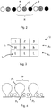
- Fig. 2 shows an example of a yarn threading using three different kinds of yarns, one being a white yarn w, one being a gray yarn g and one being a black yarn b.
- the yarn threading is such that there is provided a repeat R of three yarns.
- the gray yarn g is positioned next to the white yarn w and the black yarn b is positioned next to the gray yarn g such that the gray yarn g is positioned between the white yarn w and the black yarn b.
- Fig. 3 shows one example of a tufting instruction unit U which contains tufting instruction in association with three immediately adjacent piles to be tufted. These may be piles which are to be tufted by three immediately adjacent needles, i.e. three immediately adjacent yarns, or may be piles which are to be tufted by three subsequent stitches carried out by one and the same needle of a needle bar.
- the tufting instruction unit U is considered as being a tufting instruction unit U which is associated with three immediately adjacent yarns, i.e. needles, to which such yarns are threaded.
- the tufting instruction unit U contains tufting aspect instructions I 1 and I 2 associated with two different tufting aspects A 1 and A 2 .
- the first tufting aspect A 1 may be the height of the piles to be tufted.
- the tufting aspect instruction I 1 in association with each one of the three piles to be tufted, indicates the pile height.
- the first pile "1" shall be a high pile, which is reflected by the tufting aspect instruction I 1 "H”.
- Piles "2" and “3” shall be low piles, which is reflected by the tufting aspect instruction I 1 "h”.
- the number of different possible pile heights depends on the tufting machine which is used for carrying out the tufting process.
- the machine may be arranged for generating piles of two or three different pile heights.
- Another tufting machine may be arranged for generating any pile height between a minimum pile height and a maximum pile height.
- the second tufting aspect A 2 relates to the type of the piles to be tufted.
- all the three piles shall be loops indicated by the tufting aspect instruction I 2 "L".
- the number of different pile types depends on the tufting machine used for carrying out the tufting process. For example, this machine may be arranged for generating loops "L” or for generating cut piles.
- a row of loops will be generated by the needles of a needle bar having the structure shown in Fig. 4 .
- the first pile P 1 will be a high loop
- piles P 2 and P 3 will be low loops.
- the high loop P 1 will be made of the white yarn w
- the two low loops p 2 and p 3 will be made of the gray yarn g and the black yarn b, respectively.
- a tufting instruction unit U may be provided in which, in association with the second pile, the first tufting aspect instruction I 1 indicates "H", i.e. a high pile, while, in association with piles P 1 and P 3 , the tufting aspect instruction I 1 indicates a low pile "h". If a black fabric is to be tufted, only the third pile will have the tufting aspect instruction I 1 "H" associated therewith.
- tufting instruction units U may be defined and stored.
- the structure of these tufting instruction units may depend on the yarn threading and the repeats R and, of course, may depend on the tufting machine and, in particular, the needle bar used for carrying out a tufting process.
- this yarn threading may also be selected or defined.
- the yarn threading may be shown in a group of yarn layers wherein each of the yarn layers shows yarns having the same color.
- the yarn threading may be changed during the method of preparing the tufting process. If the yarn threading is changed during this method, then, of course, care has to be taken that, when carrying out the tufting process, the same threading will be present on the tufting machine.
- tufting instruction units will be assigned to the various pattern information layers IL 1 , IL 2 , IL 3 .
- the tufting instruction unit U shown in Fig. 3 which, in combination with the repeat R shown in Fig. 2 , will lead to the generation of white high piles and therefore will lead to a primarily white tufted area, will be assigned to the area 12 represented in the second pattern information layer IL 2 .
- a corresponding tufting instruction unit U may be assigned such that, step by step, the entire area 12 will be filled with such tufting instruction units U.
- one such pixel may be defined such as to relate to three immediately adjacent piles to be tufted in the area 12 or such as to relate to one single stitch to be carried out by a tufting machine.
- tufting instruction units U can be assigned to the area 10 represented by pattern information layer IL 1 and to the black area 14 represented by pattern information layer IL 3 .
- tufting instruction units will be assigned to the entire fabric to be tufted such that, for each single pile which is to be generated during the tufting process, information about the intended pile height and about the intended pile type will be available.
- At least one group G T of tufting aspect instruction layers is provided.
- one such group G T is provided in association with each tufting aspect.
- Figures 5 to 7 show one such group G T associated with the first tufting aspect A 1 , i.e. the pile height.
- This group G T contains one tufting aspect instruction layer TL 1 , TL 2 in association with each one of the tufting aspect instructions relating to one particular tufting aspect, in this case the tufting aspect A 1 .
- a corresponding group of tufting aspect instruction layers can and will be associated with the second tufting aspect A 2 , i.e. the pile type.
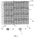
- Fig. 5 shows the two tufting aspect instruction layers TL 1 and TL 2 in a superimposed manner
- Figs. 6 and 7 show these two layers separately. It is to be noted that the area shown in Figs. 5 to 7 corresponds to the area denoted by the square V in Fig. 1 . In this area, there is a transition from the outer edge region 10 to the white-colored area 12. This transition is indicated by a transition line L shown in Figs. 5 to 7 .
- Each line of these tufting aspect instruction layers TL 1 , TL 2 represents one of the yarns of the yarn threading and therefore corresponds to the working direction of a tufting machine.
- Each column of these tufting aspect instruction layers TL 1 , TL 2 corresponds to stitches carried out by immediately consecutive needles, for example, by using the yarn threading shown in Fig. 2 .
- Each square shown in the tufting aspect instruction layers represents one stitch carried out by the needles of a needle bar of a tufting machine and therefore represents one pile which is to be generated during the tufting process. It is to be noted that there may even be stitches where no pile will be generated, which, for example, might be indicated as being a pile having a pile height "0".
- the tufting aspect instructions I 1 , I 2 will be assigned to the associated tufting aspect instruction layers TL 1 , TL 2 .
- This means that each stitch at which, for example, a high pile will have to be generated will be indicated in the tufting aspect instruction layer TL 1 associated with the tufting aspect instruction I 1 "H”.
- Each stitch for generating a low pile will be indicated in the tufting aspect instruction layer TL 2 associated with the tufting aspect instruction I 1 "h”. This can be seen in Figs. 6 and 7 .
- a representation can be obtained in which, for each single stitch to be carried out and therefore for each pile to be tufted, there will be information about the desired pile height.
- tufting aspect instruction layers of a second group containing the information about the pile types of all the piles to be tufted.
- the tufting aspect instruction layers can be considered as being entities of information of data indicating at which position or stitch which tufting aspect instruction will have to be applied and therefore which characteristics the tufted pile will have.
- These tufting aspect instruction layers may be visualized on a monitor for showing, for example, representations corresponding to the ones shown in Figs. 5 to 7 and, for example, the coloring of the entire fabric to be tufted.
- the particular tufting aspect instruction layers which shall be used for such a visualization may be selected such that, for example, only those layers showing where high piles and where loops shall be generated are shown in a superimposed manner.
- a visualization may be generated which only reflects particular information contained in all these selected layers or a visualization of the total fabric to be tufted can be generated.
- This substitution of tufting aspect instructions in the various layers either can be done pile by pile or can be done for selected areas or for all piles having the same height. After having substituted one or a plurality of the tufting aspect instructions associated with particular piles to be tufted, the corresponding layers or all the layers or the superimposed layers may once more be visualized for checking whether the desired appearance of the fabric to be tufted will be obtained or whether any further changes will be necessary.
- a tufting machine control file can be generated which contains all the information and commands necessary for controlling the tufting machine selected for carrying out the tufting process.
- This control file can be sent to or input into the controller of the machine for then carrying out the tufting process on the basis of this control file.
- This method can be carried out by using a computer program allowing a user to input the necessary information, in particular to input the pattern representation PR, and to define or select the tufting instruction units that shall be assigned to the various pattern information layers.
- a computer program may provide a plurality of toolbars or tools by means of which various functions or commands can be selected, for example, for selecting a particular tufting machine or for selecting or changing the yarn threading or, after having displayed a particular or a plurality of tufting aspect instruction layers, substituting the tufting aspect instruction associated with a particular location or with particular areas for other tufting aspect instructions.
- Such a computer program may, for example, be arranged for automatically separating areas of different color and/or structure contained in a pattern representation and associating these areas with different pattern information layers. Further, this computer program may be arranged for automatically assigning the tufting aspect instructions contained in the tufting instruction units assigned to the various pattern information layers to the various tufting aspect instruction layers provided in association with each one of the different types of tufting aspect instruction.
- the tufting aspect instruction layers may be used for directly inputting the information about the tufting aspect instructions contained in or represented by the pattern representation into these layers.
- all the tufting aspect instruction layers may be "empty", i.e. may contain no information about any kind of tufting aspect instruction, but, for example, may contain information about the size (width and/or length) or the width/length-ratio of the fabric to be tufted.
- This information may be assigned to the tufting aspect instruction layers on the basis of the pattern representation. Then, step by step, in association with each single pile to be tufted, i.e.
- the tufting aspect instructions may be entered into the various tufting aspect instruction layers for indicating where, for example, a high pile is to be tufted or where a low pile is to be tufted or where another type of pile is to be tufted.
- the tufting aspect instructions may also be a plurality of such layers or superimposed layers reflecting where which kind of pile is to be tufted.
- a visualization on the basis of one or a plurality of these tufting aspect instruction layers for showing the appearance of a fabric which will be tufted on the basis of this information.
- a yarn threading of a selected tufting machine will be considered as this yarn threading will primarily influence the color appearance of the fabric to be tufted.
- the tufting aspect instruction layers may be provided such as to have a default tufting aspect instruction assigned thereto.
- the default tufting aspect instruction I 1 may be "H", such that, in the tufting aspect instruction layer TL 1 , a high pile will be indicated at each single stitch to be carried out, while the other tufting aspect instruction layer TL 2 , which is associated with the same tufting aspect, but represents the other kind of tufting aspect instruction, i.e. "h", will be empty.
- the default tufting aspect instructions When using the pattern information layers and assigning the tufting instruction units to the pattern information layers, the default tufting aspect instructions will be overwritten by those tufting aspect instructions contained in the tufting instruction units. In locations having no tufting instruction unit assigned thereto, no changes will appear and the default tufting aspect instruction will be kept. When directly assigning the tufting aspect instructions to the various tufting aspect instruction layers, at those locations or areas to which such a tufting aspect instruction will be assigned, the default tufting aspect instruction will be overwritten.
- the amount of work necessary for obtaining the desired appearance of a fabric to be tufted can be reduced.
- the tufting aspect instruction "H" may be used as the default tufting aspect instruction, and it will not be necessary to input any further information relating to this tufting aspect.
- units of a simpler structure can be used as these units only need to contain information about the pile type, but need not contain any information about the pile height.
Landscapes
- Engineering & Computer Science (AREA)
- Chemical & Material Sciences (AREA)
- Materials Engineering (AREA)
- Textile Engineering (AREA)
- General Engineering & Computer Science (AREA)
- Physics & Mathematics (AREA)
- General Physics & Mathematics (AREA)
- Automation & Control Theory (AREA)
- Automatic Embroidering For Embroidered Or Tufted Products (AREA)
Claims (15)
- Verfahren zur Vorbereitung eines Tuftingverfahrens, umfassend die folgenden Schritte:a) Vorsehen einer Musterdarstellung (PR), die repräsentativ für ein zu tuftendes Gewebe ist,b) Vorsehen von wenigstens einer Gruppe (GT) von Tuftingmerkmal-Anweisungsebenen (TL1, TL2), welche Tuftingmerkmal-Anweisungsebenen (TL1 TL2) umfasst, wobei jede der Tuftingmerkmal-Anweisungsebenen (TL1, TL2) einer bestimmten Tuftingmerkmal-Anweisung (I1, I2) zugeordnet ist, welche sich auf ein Tuftingmerkmal (A1, A2) bezieht, und eine Informationsgesamtheit bildet, welche jene Bereiche der Musterdarstellung repräsentiert, in welchen die eine bestimmte Tuftingmerkmal-Anweisung gelten soll,c) Zuweisen wenigstens einer Tuftingmerkmal-Anweisung (I1, I2) zu wenigstens einer der Tuftingmerkmal-Anweisungsebenen (TL1, TL2),wobei ein erstes Tuftingmerkmal (A1) die Polhöhe (H, h) ist und wobei eine erste Tuftingmerkmal-Anweisung (I1), welche sich auf das erste Tuftingmerkmal (A1) bezieht, die Höhe (H, h) eines zu tuftenden Pols als eine von wenigstens zwei verschiedenen Polhöhen (H, h) angibt, wobei jede Tuftingmerkmal-Anweisungsebene (TL1, TL2) einer ersten Gruppe (GT) von Tuftingmerkmal-Anweisungsebenen (TL1, TL2) Bereiche der Musterdarstellung (PR) repräsentiert, welchen dieselbe erste Tuftingmerkmal-Anweisung (I1) zugeordnet ist, welche eine der wenigstens zwei unterschiedlichen Polhöhen (H, h) anzeigt,
und/oder
wobei ein zweites Tuftingmerkmal (A2) die Polart (L) ist und wobei eine zweite Tuftingmerkmal-Anweisung (I2), welche sich auf das zweiten Tuftingmerkmal (A2) bezieht, die Art (L) eines zu tuftenden Pols als Schlinge oder als Schnittpol anzeigt, wobei jede Tuftingmerkmal-Anweisungsebene einer zweiten Gruppe von Tuftingmerkmal-Anweisungsebenen Bereiche der Musterdarstellung (PR) repräsentiert, welchen dieselbe zweite Tuftingmerkmal-Anweisung (I2) zugeordnet ist, welche eine Schlinge oder einen Schnittpol anzeigt. - Verfahren nach Anspruch 1, wobei:Schritt a) das Vorsehen der Musterdarstellung (PR) als eine Musterinformationsdarstellung (IR) umfasst, die das Muster des zu tuftenden Gewebes darstellt, wobei das Verfahren ferner umfasst:einen Schritt a1) des Vorsehens einer Gruppe (GI) von Musterinformationsebenen (IL1, IL2, IL3) auf der Grundlage der Musterdarstellung (IR), wobei die Gruppe (GI) von Musterinformationsebenen (IL1, IL2, IL3) wenigstens eine Musterinformationsebene (IL1, IL2, IL3) umfasst, wobei jede Musterinformationsebene (IL1, IL2, IL3) Bereiche (10, 12, 14) der Musterinformationsdarstellung (IR) repräsentiert, denen die gleiche Musterinformation zugeordnet ist, undeinen Schritt a2) des Vorsehens wenigstens einer Tufting-Anweisungseinheit (U), wobei jede Tufting-Anweisungseinheit (U) wenigstens eine Tuftingmerkmal-Anweisung (I1, I2) umfasst,Schritt c) das Zuweisen von Tufting-Anweisungseinheiten (U) zu wenigstens einer Musterinformationsebene (IL1, IL2, IL3) umfasst und dadurch das Zuweisen von Tuftingmerkmal-Anweisungen (I1, I2) der Tufting-Anweisungseinheiten (U) zu den zugehörigen Tuftingmerkmal-Anweisungsebenen (TL1, TL2).
- Verfahren nach Anspruch 2, wobei in Verbindung mit jeder Musterinformationsebene (IL1, IL2, IL3) wenigstens eine Tufting-Anweisungseinheit (U) vorgesehen ist, und/oder wobei wenigstens eine Tufting-Anweisungseinheit (U) auf eine Vielzahl von Musterinformationsebenen (IL1, IL2, IL3) angewendet wird.
- Verfahren nach einem der Ansprüche 2 oder 3, wobei wenigstens eine Tufting-Anweisungseinheit (U) wiederholt derselben Musterinformationsebene (IL2) zugeordnet wird.
- Verfahren nach einem der Ansprüche 2 bis 4, wobei wenigstens eine Tufting-Anweisungseinheit (U) einer Gruppe (Gp) von zu tuftenden Polen (P1, P2, P3) zugeordnet wird, wobei die Gruppe (Gp) von Polen (P1, P2, P3) wenigstens einen Pol (P1, P2, P3) umfasst, wobei vorzugsweise die Gruppe (Gp) von Polen (P1, P2, P3) eine Vielzahl von gleichzeitig zu tuftenden Polen (P1, P2, P3) mittels unmittelbar benachbarter, auf einem Nadelbalken einer Tuftingmaschine angeordneter Nadeln umfasst und/oder eine Vielzahl von Polen umfasst, die mittels unmittelbar aufeinanderfolgender Stiche derselben, auf einem Nadelbalken einer Tuftingmaschine angeordneter Nadel zu tuften sind.
- Verfahren nach Anspruch 5, wobei eine Tufting-Anweisungseinheit (U), die einer Gruppe (Gp) von zu tuftenden Polen (P1, P2, P3) zugeordnet ist, für jeden Pol (P1, P2, P3) dieser Gruppe (Gp) von Polen (P1, P2, P3) eine erste Tuftingmerkmal-Anweisung (I1) und eine zweite Tuftingmerkmal-Anweisung (I2) umfasst.
- Verfahren nach einem der vorhergehenden Ansprüche, wobei in Schritt b) wenigstens eine Gruppe (GT) von Tuftingmerkmal-Anweisungsebenen (TL1, TL2) derart vorgesehen ist, dass sie eine vorbestimmte Standard-Tuftingmerkmal-Anweisung (I1, I2) in Verbindung mit dem gesamten zu tuftenden Gewebe darstellt.
- Verfahren nach den Ansprüchen 2 und 7, wobei Schritt c) das Ersetzen einer Tuftingmerkmal-Anweisung (I1, I2) einer Tuftingmerkmal-Anweisungseinheit (U), die einer Musterinformationsebene (IL1, IL2, IL3) zugeordnet ist, durch wenigstens eine Standard-Tuftingmerkmal-Anweisung (I1, I2) umfasst.
- Verfahren nach einem der vorhergehenden Ansprüche, welches ferner den Schritt des Ersetzens wenigstens einer anderen Tuftingmerkmal-Anweisung (I1, I2), die sich auf dasselbe Tuftingmerkmal (A1, A2) bezieht, durch wenigstens eine Tuftingmerkmal-Anweisung (I1, I2) wenigstens einer Tuftingmerkmal-Anweisungsebene (TL1, TL2) umfasst.
- Verfahren nach einem der vorhergehenden Ansprüche, welches ferner den Schritt des Auswählens einer aus einer Mehrzahl von Tuftingmaschinen umfasst, die vorzugsweise einen vorbestimmten Fadeneinzug haben, und/oder den Schritt des Bestimmens eines zum Tuften des Gewebes zu verwendenden Fadeneinzugs umfasst, wobei der Fadeneinzug die Reihenfolge der Fäden in Verbindung mit Nadeln einer Nadelstange einer Tuftingmaschine definiert.
- Verfahren nach den Ansprüchen 5 und 10, wobei der Fadeneinzug einen Fadenrapport (R) umfasst, wobei wenigstens eine Gruppe (Gp) von Polen (P1, P2, P3) eine Gruppe (G) ist, die mit den Fäden eines Fadenrapportes (R) getuftet werden soll.
- Verfahren nach Anspruch 2 und einem der Ansprüche 10 oder 11, wobei wenigstens eine Tufting-Anweisungseinheit (U), vorzugsweise alle Tufting-Anweisungseinheiten (U), auf der Grundlage der in den Musterinformationsebenen (IL1, IL2, IL3) enthaltenen Informationen und/oder auf der Grundlage des Fadeneinzugs definiert und/oder ausgewählt wird/werden.
- Verfahren nach einem der vorhergehenden Ansprüche, welches ferner den Schritt des Erzeugens einer Visualisierung eines zu tuftenden Gewebes auf der Grundlage der Tuftingmerkmal-Anweisungen (I1, I2)umfasst, die in wenigstens einer der Tuftingmerkmal-Anweisungsebenen (TL1, TL2) enthalten sind.
- Verfahren nach einem der vorhergehenden Ansprüche, welches ferner den Schritt des Erzeugens einer Tuftingmaschinensteuerdatei auf der Grundlage der Tuftingmerkmal-Anweisungen (I1, I2) aller Tuftingmerkmal-Anweisungsebenen (TL1, TL2), denen Tuftingmerkmal-Anweisungen (I1, I2) zugeordnet sind, umfasst.
- Verfahren zum Tuften eines Gewebes, umfassend die Schritte:- Erzeugen einer Tuftingmaschinensteuerdatei unter Verwendung des Verfahrens nach einem der vorhergehenden Ansprüche,- Weiterleiten der Tuftingmaschinensteuerdatei an die Tuftingmaschine, die zum Ausführen des Tuftingverfahrens ausgewählt wurde,- Betreiben der Tuftingmaschine auf der Basis der Tuftingmaschinensteuerdatei.
Priority Applications (1)
| Application Number | Priority Date | Filing Date | Title |
|---|---|---|---|
| PL16770726T PL3356593T3 (pl) | 2015-09-28 | 2016-09-15 | Sposób przygotowania procesu tkania dywanowego |
Applications Claiming Priority (2)
| Application Number | Priority Date | Filing Date | Title |
|---|---|---|---|
| EP15187113.4A EP3147399A1 (de) | 2015-09-28 | 2015-09-28 | Verfahren zur herstellung eines tuftingverfahrens |
| PCT/EP2016/071862 WO2017055099A1 (en) | 2015-09-28 | 2016-09-15 | Method of preparing a tufting process |
Publications (2)
| Publication Number | Publication Date |
|---|---|
| EP3356593A1 EP3356593A1 (de) | 2018-08-08 |
| EP3356593B1 true EP3356593B1 (de) | 2020-07-29 |
Family
ID=54238308
Family Applications (2)
| Application Number | Title | Priority Date | Filing Date |
|---|---|---|---|
| EP15187113.4A Withdrawn EP3147399A1 (de) | 2015-09-28 | 2015-09-28 | Verfahren zur herstellung eines tuftingverfahrens |
| EP16770726.4A Active EP3356593B1 (de) | 2015-09-28 | 2016-09-15 | Verfahren zur herstellung eines tuftingverfahrens |
Family Applications Before (1)
| Application Number | Title | Priority Date | Filing Date |
|---|---|---|---|
| EP15187113.4A Withdrawn EP3147399A1 (de) | 2015-09-28 | 2015-09-28 | Verfahren zur herstellung eines tuftingverfahrens |
Country Status (9)
| Country | Link |
|---|---|
| US (1) | US10767295B2 (de) |
| EP (2) | EP3147399A1 (de) |
| CN (1) | CN108138413B (de) |
| AU (1) | AU2016330228B2 (de) |
| DK (1) | DK3356593T3 (de) |
| ES (1) | ES2817006T3 (de) |
| PL (1) | PL3356593T3 (de) |
| WO (1) | WO2017055099A1 (de) |
| ZA (1) | ZA201801428B (de) |
Families Citing this family (2)
| Publication number | Priority date | Publication date | Assignee | Title |
|---|---|---|---|---|
| EP3299502A1 (de) * | 2016-09-22 | 2018-03-28 | NV Michel van de Wiele | Verfahren zur herstellung eines tufting-prozesses zum tuften eines gewebes, vorzugsweise eines teppichs |
| EP3348692A1 (de) * | 2017-01-12 | 2018-07-18 | NV Michel van de Wiele | Tuftingmaschine, verfahren zum tuften eines gewebes und tufting-gewebe |
Family Cites Families (18)
| Publication number | Priority date | Publication date | Assignee | Title |
|---|---|---|---|---|
| US2966866A (en) * | 1952-12-24 | 1961-01-03 | Cobble Brothers Machinery Comp | Method of and apparatus for making patterned tufted pile fabric |
| US3067701A (en) * | 1959-07-31 | 1962-12-11 | A & M Karagheusion Inc | Apparatus for forming tufted patterns |
| US3943865A (en) * | 1966-03-07 | 1976-03-16 | Deering Milliken Research Corporation | Controlled delivery of yarn |
| JPS5532517A (en) * | 1978-08-29 | 1980-03-07 | Janome Sewing Machine Co Ltd | Method of generating pattern of electric sewing machine |
| US6244203B1 (en) * | 1996-11-27 | 2001-06-12 | Tuftco Corp. | Independent servo motor controlled scroll-type pattern attachment for tufting machine and computerized design system |
| AUPP576698A0 (en) * | 1998-09-07 | 1998-10-01 | Wilcom Pty Ltd | Curved line fill stitching in embroidery designs |
| WO2005026863A2 (en) * | 2003-09-18 | 2005-03-24 | Studiostampa Inc. | Method for generating a non-periodic visual pattern |
| US7634326B2 (en) * | 2006-05-23 | 2009-12-15 | Card-Monroe Corp. | System and method for forming tufted patterns |
| ATE507338T1 (de) * | 2007-10-23 | 2011-05-15 | Card Monroe Corp | System und verfahren zur fadenführung bei einer tuftingmaschine |
| US8225727B2 (en) * | 2008-01-04 | 2012-07-24 | Wilcom Pty Ltd | Tufting machine |
| US8359989B2 (en) * | 2008-02-15 | 2013-01-29 | Card-Monroe Corp. | Stitch distribution control system for tufting machines |
| US8141505B2 (en) * | 2008-02-15 | 2012-03-27 | Card-Monroe Corp. | Yarn color placement system |
| GB2486103B (en) * | 2009-08-25 | 2014-05-07 | Card Monroe Corp | Integrated motor drive system for motor driven yarn feed attachments |
| WO2012074642A1 (en) * | 2010-10-28 | 2012-06-07 | Shaw Industries Group, Inc. | Methods and devices for controlling a tufting machine for forming tufted carpet |
| CN103792884A (zh) * | 2012-10-31 | 2014-05-14 | 日照贝尔机械有限公司 | 地毯打样机数控系统的设计 |
| EP2997187B1 (de) * | 2013-05-13 | 2018-08-29 | Card-Monroe Corporation | System und verfahren zur bildung eines strukturierten künstlichen/synthetischen reitsportuntergrundes |
| JP2015008869A (ja) * | 2013-06-28 | 2015-01-19 | ブラザー工業株式会社 | ミシン、縫製プログラム、及び縫製方法 |
| CN203807750U (zh) * | 2014-04-11 | 2014-09-03 | 乐清市塔夫特机械有限公司 | 一种多色电脑提花簇绒机高割低圈勾绒系统及簇绒机 |
-
2015
- 2015-09-28 EP EP15187113.4A patent/EP3147399A1/de not_active Withdrawn
-
2016
- 2016-09-15 US US15/763,221 patent/US10767295B2/en active Active
- 2016-09-15 AU AU2016330228A patent/AU2016330228B2/en not_active Ceased
- 2016-09-15 EP EP16770726.4A patent/EP3356593B1/de active Active
- 2016-09-15 ES ES16770726T patent/ES2817006T3/es active Active
- 2016-09-15 WO PCT/EP2016/071862 patent/WO2017055099A1/en not_active Ceased
- 2016-09-15 CN CN201680054335.9A patent/CN108138413B/zh active Active
- 2016-09-15 PL PL16770726T patent/PL3356593T3/pl unknown
- 2016-09-15 DK DK16770726.4T patent/DK3356593T3/da active
-
2018
- 2018-02-28 ZA ZA2018/01428A patent/ZA201801428B/en unknown
Non-Patent Citations (1)
| Title |
|---|
| None * |
Also Published As
| Publication number | Publication date |
|---|---|
| ES2817006T3 (es) | 2021-04-06 |
| EP3147399A1 (de) | 2017-03-29 |
| WO2017055099A1 (en) | 2017-04-06 |
| ZA201801428B (en) | 2019-07-31 |
| EP3356593A1 (de) | 2018-08-08 |
| US20180282928A1 (en) | 2018-10-04 |
| AU2016330228A1 (en) | 2018-04-05 |
| CN108138413B (zh) | 2021-04-27 |
| US10767295B2 (en) | 2020-09-08 |
| CN108138413A (zh) | 2018-06-08 |
| AU2016330228B2 (en) | 2019-05-16 |
| DK3356593T3 (da) | 2020-10-19 |
| PL3356593T3 (pl) | 2020-12-28 |
Similar Documents
| Publication | Publication Date | Title |
|---|---|---|
| US6611730B1 (en) | Device and method of designing knit products to be manufactured on a knitting machine | |
| KR950000478B1 (ko) | 니팅 설계시스템과 그 시스템용의 니팅 데이타의 작성방법 | |
| US12037727B2 (en) | Variable density tufting patterns | |
| US10087561B2 (en) | Balancing yarn use in designing tufted patterns for textiles | |
| US10767295B2 (en) | Method of preparing a tufting process | |
| JP4425999B2 (ja) | 選択指定確認表示機能を備えた刺繍データ作成装置 | |
| US10954617B2 (en) | Method of preparing a tufting process for tufting fabric, in particular carpet | |
| US12203200B2 (en) | Outline void pattern | |
| EP3516102B1 (de) | Verfahren zum tuften eines gewebes, vorzugsweise eines teppichs | |
| WO2017130734A1 (ja) | ミシン及び縫製データ編集プログラム | |
| CN109804113B (zh) | 准备用于对织物、特别是地毯进行簇绒的簇绒过程的方法 | |
| HK1262090A1 (en) | Balancing yarn use in designing tufted pattern for textiles | |
| JPH04126186A (ja) | 刺繍データ表示装置 |
Legal Events
| Date | Code | Title | Description |
|---|---|---|---|
| STAA | Information on the status of an ep patent application or granted ep patent |
Free format text: STATUS: UNKNOWN |
|
| STAA | Information on the status of an ep patent application or granted ep patent |
Free format text: STATUS: THE INTERNATIONAL PUBLICATION HAS BEEN MADE |
|
| PUAI | Public reference made under article 153(3) epc to a published international application that has entered the european phase |
Free format text: ORIGINAL CODE: 0009012 |
|
| STAA | Information on the status of an ep patent application or granted ep patent |
Free format text: STATUS: REQUEST FOR EXAMINATION WAS MADE |
|
| 17P | Request for examination filed |
Effective date: 20180423 |
|
| AK | Designated contracting states |
Kind code of ref document: A1 Designated state(s): AL AT BE BG CH CY CZ DE DK EE ES FI FR GB GR HR HU IE IS IT LI LT LU LV MC MK MT NL NO PL PT RO RS SE SI SK SM TR |
|
| AX | Request for extension of the european patent |
Extension state: BA ME |
|
| DAV | Request for validation of the european patent (deleted) | ||
| DAX | Request for extension of the european patent (deleted) | ||
| STAA | Information on the status of an ep patent application or granted ep patent |
Free format text: STATUS: EXAMINATION IS IN PROGRESS |
|
| 17Q | First examination report despatched |
Effective date: 20190219 |
|
| RAP1 | Party data changed (applicant data changed or rights of an application transferred) |
Owner name: VANDEWIELE NV |
|
| RIC1 | Information provided on ipc code assigned before grant |
Ipc: D05C 15/26 20060101AFI20200124BHEP |
|
| GRAJ | Information related to disapproval of communication of intention to grant by the applicant or resumption of examination proceedings by the epo deleted |
Free format text: ORIGINAL CODE: EPIDOSDIGR1 |
|
| STAA | Information on the status of an ep patent application or granted ep patent |
Free format text: STATUS: GRANT OF PATENT IS INTENDED |
|
| GRAP | Despatch of communication of intention to grant a patent |
Free format text: ORIGINAL CODE: EPIDOSNIGR1 |
|
| INTG | Intention to grant announced |
Effective date: 20200323 |
|
| GRAS | Grant fee paid |
Free format text: ORIGINAL CODE: EPIDOSNIGR3 |
|
| GRAA | (expected) grant |
Free format text: ORIGINAL CODE: 0009210 |
|
| STAA | Information on the status of an ep patent application or granted ep patent |
Free format text: STATUS: THE PATENT HAS BEEN GRANTED |
|
| AK | Designated contracting states |
Kind code of ref document: B1 Designated state(s): AL AT BE BG CH CY CZ DE DK EE ES FI FR GB GR HR HU IE IS IT LI LT LU LV MC MK MT NL NO PL PT RO RS SE SI SK SM TR |
|
| REG | Reference to a national code |
Ref country code: CH Ref legal event code: EP |
|
| REG | Reference to a national code |
Ref country code: AT Ref legal event code: REF Ref document number: 1295914 Country of ref document: AT Kind code of ref document: T Effective date: 20200815 |
|
| REG | Reference to a national code |
Ref country code: IE Ref legal event code: FG4D |
|
| REG | Reference to a national code |
Ref country code: DE Ref legal event code: R096 Ref document number: 602016040887 Country of ref document: DE |
|
| REG | Reference to a national code |
Ref country code: SE Ref legal event code: TRGR |
|
| REG | Reference to a national code |
Ref country code: DK Ref legal event code: T3 Effective date: 20201013 |
|
| REG | Reference to a national code |
Ref country code: NL Ref legal event code: FP |
|
| REG | Reference to a national code |
Ref country code: LT Ref legal event code: MG4D |
|
| REG | Reference to a national code |
Ref country code: AT Ref legal event code: MK05 Ref document number: 1295914 Country of ref document: AT Kind code of ref document: T Effective date: 20200729 |
|
| PG25 | Lapsed in a contracting state [announced via postgrant information from national office to epo] |
Ref country code: GR Free format text: LAPSE BECAUSE OF FAILURE TO SUBMIT A TRANSLATION OF THE DESCRIPTION OR TO PAY THE FEE WITHIN THE PRESCRIBED TIME-LIMIT Effective date: 20201030 Ref country code: HR Free format text: LAPSE BECAUSE OF FAILURE TO SUBMIT A TRANSLATION OF THE DESCRIPTION OR TO PAY THE FEE WITHIN THE PRESCRIBED TIME-LIMIT Effective date: 20200729 Ref country code: AT Free format text: LAPSE BECAUSE OF FAILURE TO SUBMIT A TRANSLATION OF THE DESCRIPTION OR TO PAY THE FEE WITHIN THE PRESCRIBED TIME-LIMIT Effective date: 20200729 Ref country code: LT Free format text: LAPSE BECAUSE OF FAILURE TO SUBMIT A TRANSLATION OF THE DESCRIPTION OR TO PAY THE FEE WITHIN THE PRESCRIBED TIME-LIMIT Effective date: 20200729 Ref country code: BG Free format text: LAPSE BECAUSE OF FAILURE TO SUBMIT A TRANSLATION OF THE DESCRIPTION OR TO PAY THE FEE WITHIN THE PRESCRIBED TIME-LIMIT Effective date: 20201029 Ref country code: NO Free format text: LAPSE BECAUSE OF FAILURE TO SUBMIT A TRANSLATION OF THE DESCRIPTION OR TO PAY THE FEE WITHIN THE PRESCRIBED TIME-LIMIT Effective date: 20201029 Ref country code: PT Free format text: LAPSE BECAUSE OF FAILURE TO SUBMIT A TRANSLATION OF THE DESCRIPTION OR TO PAY THE FEE WITHIN THE PRESCRIBED TIME-LIMIT Effective date: 20201130 Ref country code: FI Free format text: LAPSE BECAUSE OF FAILURE TO SUBMIT A TRANSLATION OF THE DESCRIPTION OR TO PAY THE FEE WITHIN THE PRESCRIBED TIME-LIMIT Effective date: 20200729 |
|
| PG25 | Lapsed in a contracting state [announced via postgrant information from national office to epo] |
Ref country code: LV Free format text: LAPSE BECAUSE OF FAILURE TO SUBMIT A TRANSLATION OF THE DESCRIPTION OR TO PAY THE FEE WITHIN THE PRESCRIBED TIME-LIMIT Effective date: 20200729 Ref country code: RS Free format text: LAPSE BECAUSE OF FAILURE TO SUBMIT A TRANSLATION OF THE DESCRIPTION OR TO PAY THE FEE WITHIN THE PRESCRIBED TIME-LIMIT Effective date: 20200729 Ref country code: IS Free format text: LAPSE BECAUSE OF FAILURE TO SUBMIT A TRANSLATION OF THE DESCRIPTION OR TO PAY THE FEE WITHIN THE PRESCRIBED TIME-LIMIT Effective date: 20201129 |
|
| REG | Reference to a national code |
Ref country code: ES Ref legal event code: FG2A Ref document number: 2817006 Country of ref document: ES Kind code of ref document: T3 Effective date: 20210406 |
|
| PG25 | Lapsed in a contracting state [announced via postgrant information from national office to epo] |
Ref country code: RO Free format text: LAPSE BECAUSE OF FAILURE TO SUBMIT A TRANSLATION OF THE DESCRIPTION OR TO PAY THE FEE WITHIN THE PRESCRIBED TIME-LIMIT Effective date: 20200729 Ref country code: CZ Free format text: LAPSE BECAUSE OF FAILURE TO SUBMIT A TRANSLATION OF THE DESCRIPTION OR TO PAY THE FEE WITHIN THE PRESCRIBED TIME-LIMIT Effective date: 20200729 Ref country code: EE Free format text: LAPSE BECAUSE OF FAILURE TO SUBMIT A TRANSLATION OF THE DESCRIPTION OR TO PAY THE FEE WITHIN THE PRESCRIBED TIME-LIMIT Effective date: 20200729 Ref country code: SM Free format text: LAPSE BECAUSE OF FAILURE TO SUBMIT A TRANSLATION OF THE DESCRIPTION OR TO PAY THE FEE WITHIN THE PRESCRIBED TIME-LIMIT Effective date: 20200729 |
|
| REG | Reference to a national code |
Ref country code: CH Ref legal event code: PL Ref country code: DE Ref legal event code: R097 Ref document number: 602016040887 Country of ref document: DE |
|
| PG25 | Lapsed in a contracting state [announced via postgrant information from national office to epo] |
Ref country code: AL Free format text: LAPSE BECAUSE OF FAILURE TO SUBMIT A TRANSLATION OF THE DESCRIPTION OR TO PAY THE FEE WITHIN THE PRESCRIBED TIME-LIMIT Effective date: 20200729 |
|
| PLBE | No opposition filed within time limit |
Free format text: ORIGINAL CODE: 0009261 |
|
| STAA | Information on the status of an ep patent application or granted ep patent |
Free format text: STATUS: NO OPPOSITION FILED WITHIN TIME LIMIT |
|
| PG25 | Lapsed in a contracting state [announced via postgrant information from national office to epo] |
Ref country code: LU Free format text: LAPSE BECAUSE OF NON-PAYMENT OF DUE FEES Effective date: 20200915 Ref country code: SK Free format text: LAPSE BECAUSE OF FAILURE TO SUBMIT A TRANSLATION OF THE DESCRIPTION OR TO PAY THE FEE WITHIN THE PRESCRIBED TIME-LIMIT Effective date: 20200729 |
|
| 26N | No opposition filed |
Effective date: 20210430 |
|
| PG25 | Lapsed in a contracting state [announced via postgrant information from national office to epo] |
Ref country code: CH Free format text: LAPSE BECAUSE OF NON-PAYMENT OF DUE FEES Effective date: 20200930 Ref country code: SI Free format text: LAPSE BECAUSE OF FAILURE TO SUBMIT A TRANSLATION OF THE DESCRIPTION OR TO PAY THE FEE WITHIN THE PRESCRIBED TIME-LIMIT Effective date: 20200729 Ref country code: IE Free format text: LAPSE BECAUSE OF NON-PAYMENT OF DUE FEES Effective date: 20200915 Ref country code: LI Free format text: LAPSE BECAUSE OF NON-PAYMENT OF DUE FEES Effective date: 20200930 |
|
| PG25 | Lapsed in a contracting state [announced via postgrant information from national office to epo] |
Ref country code: MT Free format text: LAPSE BECAUSE OF FAILURE TO SUBMIT A TRANSLATION OF THE DESCRIPTION OR TO PAY THE FEE WITHIN THE PRESCRIBED TIME-LIMIT Effective date: 20200729 Ref country code: CY Free format text: LAPSE BECAUSE OF FAILURE TO SUBMIT A TRANSLATION OF THE DESCRIPTION OR TO PAY THE FEE WITHIN THE PRESCRIBED TIME-LIMIT Effective date: 20200729 |
|
| PG25 | Lapsed in a contracting state [announced via postgrant information from national office to epo] |
Ref country code: MK Free format text: LAPSE BECAUSE OF FAILURE TO SUBMIT A TRANSLATION OF THE DESCRIPTION OR TO PAY THE FEE WITHIN THE PRESCRIBED TIME-LIMIT Effective date: 20200729 Ref country code: MC Free format text: LAPSE BECAUSE OF FAILURE TO SUBMIT A TRANSLATION OF THE DESCRIPTION OR TO PAY THE FEE WITHIN THE PRESCRIBED TIME-LIMIT Effective date: 20200729 |
|
| P01 | Opt-out of the competence of the unified patent court (upc) registered |
Effective date: 20230517 |
|
| PGFP | Annual fee paid to national office [announced via postgrant information from national office to epo] |
Ref country code: NL Payment date: 20230920 Year of fee payment: 8 |
|
| PGFP | Annual fee paid to national office [announced via postgrant information from national office to epo] |
Ref country code: SE Payment date: 20230920 Year of fee payment: 8 Ref country code: PL Payment date: 20230908 Year of fee payment: 8 Ref country code: FR Payment date: 20230928 Year of fee payment: 8 Ref country code: DK Payment date: 20230925 Year of fee payment: 8 |
|
| PGFP | Annual fee paid to national office [announced via postgrant information from national office to epo] |
Ref country code: ES Payment date: 20231124 Year of fee payment: 8 |
|
| PGFP | Annual fee paid to national office [announced via postgrant information from national office to epo] |
Ref country code: IT Payment date: 20230927 Year of fee payment: 8 |
|
| REG | Reference to a national code |
Ref country code: DK Ref legal event code: EBP Effective date: 20240930 |
|
| REG | Reference to a national code |
Ref country code: SE Ref legal event code: EUG |
|
| REG | Reference to a national code |
Ref country code: NL Ref legal event code: MM Effective date: 20241001 |
|
| PG25 | Lapsed in a contracting state [announced via postgrant information from national office to epo] |
Ref country code: NL Free format text: LAPSE BECAUSE OF NON-PAYMENT OF DUE FEES Effective date: 20241001 |
|
| PG25 | Lapsed in a contracting state [announced via postgrant information from national office to epo] |
Ref country code: IT Free format text: LAPSE BECAUSE OF NON-PAYMENT OF DUE FEES Effective date: 20240915 |
|
| PG25 | Lapsed in a contracting state [announced via postgrant information from national office to epo] |
Ref country code: FR Free format text: LAPSE BECAUSE OF NON-PAYMENT OF DUE FEES Effective date: 20240930 |
|
| PG25 | Lapsed in a contracting state [announced via postgrant information from national office to epo] |
Ref country code: DK Free format text: LAPSE BECAUSE OF NON-PAYMENT OF DUE FEES Effective date: 20240930 |
|
| PGFP | Annual fee paid to national office [announced via postgrant information from national office to epo] |
Ref country code: DE Payment date: 20250919 Year of fee payment: 10 |
|
| PG25 | Lapsed in a contracting state [announced via postgrant information from national office to epo] |
Ref country code: SE Free format text: LAPSE BECAUSE OF NON-PAYMENT OF DUE FEES Effective date: 20240916 |
|
| PGFP | Annual fee paid to national office [announced via postgrant information from national office to epo] |
Ref country code: TR Payment date: 20250909 Year of fee payment: 10 |
|
| PGFP | Annual fee paid to national office [announced via postgrant information from national office to epo] |
Ref country code: BE Payment date: 20250918 Year of fee payment: 10 Ref country code: GB Payment date: 20250919 Year of fee payment: 10 |
|
| REG | Reference to a national code |
Ref country code: ES Ref legal event code: FD2A Effective date: 20251031 |
|
| PG25 | Lapsed in a contracting state [announced via postgrant information from national office to epo] |
Ref country code: ES Free format text: LAPSE BECAUSE OF NON-PAYMENT OF DUE FEES Effective date: 20240916 |
|
| PG25 | Lapsed in a contracting state [announced via postgrant information from national office to epo] |
Ref country code: PL Free format text: LAPSE BECAUSE OF NON-PAYMENT OF DUE FEES Effective date: 20240915 |