EP3356733B1 - Ensemble lampe tubulaire à del - Google Patents
Ensemble lampe tubulaire à del Download PDFInfo
- Publication number
- EP3356733B1 EP3356733B1 EP16791450.6A EP16791450A EP3356733B1 EP 3356733 B1 EP3356733 B1 EP 3356733B1 EP 16791450 A EP16791450 A EP 16791450A EP 3356733 B1 EP3356733 B1 EP 3356733B1
- Authority
- EP
- European Patent Office
- Prior art keywords
- contacts
- assembly
- longitudinal direction
- tubular lamp
- tube housing
- Prior art date
- Legal status (The legal status is an assumption and is not a legal conclusion. Google has not performed a legal analysis and makes no representation as to the accuracy of the status listed.)
- Not-in-force
Links
Images




Classifications
-
- F—MECHANICAL ENGINEERING; LIGHTING; HEATING; WEAPONS; BLASTING
- F21—LIGHTING
- F21S—NON-PORTABLE LIGHTING DEVICES; SYSTEMS THEREOF; VEHICLE LIGHTING DEVICES SPECIALLY ADAPTED FOR VEHICLE EXTERIORS
- F21S4/00—Lighting devices or systems using a string or strip of light sources
- F21S4/20—Lighting devices or systems using a string or strip of light sources with light sources held by or within elongate supports
- F21S4/28—Lighting devices or systems using a string or strip of light sources with light sources held by or within elongate supports rigid, e.g. LED bars
-
- F—MECHANICAL ENGINEERING; LIGHTING; HEATING; WEAPONS; BLASTING
- F21—LIGHTING
- F21K—NON-ELECTRIC LIGHT SOURCES USING LUMINESCENCE; LIGHT SOURCES USING ELECTROCHEMILUMINESCENCE; LIGHT SOURCES USING CHARGES OF COMBUSTIBLE MATERIAL; LIGHT SOURCES USING SEMICONDUCTOR DEVICES AS LIGHT-GENERATING ELEMENTS; LIGHT SOURCES NOT OTHERWISE PROVIDED FOR
- F21K9/00—Light sources using semiconductor devices as light-generating elements, e.g. using light-emitting diodes [LED] or lasers
- F21K9/20—Light sources comprising attachment means
- F21K9/27—Retrofit light sources for lighting devices with two fittings for each light source, e.g. for substitution of fluorescent tubes
- F21K9/272—Details of end parts, i.e. the parts that connect the light source to a fitting; Arrangement of components within end parts
-
- F—MECHANICAL ENGINEERING; LIGHTING; HEATING; WEAPONS; BLASTING
- F21—LIGHTING
- F21V—FUNCTIONAL FEATURES OR DETAILS OF LIGHTING DEVICES OR SYSTEMS THEREOF; STRUCTURAL COMBINATIONS OF LIGHTING DEVICES WITH OTHER ARTICLES, NOT OTHERWISE PROVIDED FOR
- F21V17/00—Fastening of component parts of lighting devices, e.g. shades, globes, refractors, reflectors, filters, screens, grids or protective cages
- F21V17/10—Fastening of component parts of lighting devices, e.g. shades, globes, refractors, reflectors, filters, screens, grids or protective cages characterised by specific fastening means or way of fastening
- F21V17/104—Fastening of component parts of lighting devices, e.g. shades, globes, refractors, reflectors, filters, screens, grids or protective cages characterised by specific fastening means or way of fastening using feather joints, e.g. tongues and grooves, with or without friction
-
- F—MECHANICAL ENGINEERING; LIGHTING; HEATING; WEAPONS; BLASTING
- F21—LIGHTING
- F21V—FUNCTIONAL FEATURES OR DETAILS OF LIGHTING DEVICES OR SYSTEMS THEREOF; STRUCTURAL COMBINATIONS OF LIGHTING DEVICES WITH OTHER ARTICLES, NOT OTHERWISE PROVIDED FOR
- F21V19/00—Fastening of light sources or lamp holders
- F21V19/001—Fastening of light sources or lamp holders the light sources being semiconductors devices, e.g. LEDs
- F21V19/003—Fastening of light source holders, e.g. of circuit boards or substrates holding light sources
- F21V19/0045—Fastening of light source holders, e.g. of circuit boards or substrates holding light sources by tongue and groove connections, e.g. dovetail interlocking means fixed by sliding
-
- F—MECHANICAL ENGINEERING; LIGHTING; HEATING; WEAPONS; BLASTING
- F21—LIGHTING
- F21Y—INDEXING SCHEME ASSOCIATED WITH SUBCLASSES F21K, F21L, F21S and F21V, RELATING TO THE FORM OR THE KIND OF THE LIGHT SOURCES OR OF THE COLOUR OF THE LIGHT EMITTED
- F21Y2103/00—Elongate light sources, e.g. fluorescent tubes
- F21Y2103/10—Elongate light sources, e.g. fluorescent tubes comprising a linear array of point-like light-generating elements
-
- F—MECHANICAL ENGINEERING; LIGHTING; HEATING; WEAPONS; BLASTING
- F21—LIGHTING
- F21Y—INDEXING SCHEME ASSOCIATED WITH SUBCLASSES F21K, F21L, F21S and F21V, RELATING TO THE FORM OR THE KIND OF THE LIGHT SOURCES OR OF THE COLOUR OF THE LIGHT EMITTED
- F21Y2115/00—Light-generating elements of semiconductor light sources
- F21Y2115/10—Light-emitting diodes [LED]
Definitions
- the present invention relates to a light emitting diode (LED) tubular lamp assembly according to the preamble of claim 1.
- LED light emitting diode
- Such lamp assemblies are known from EP 2 216 859 A1 .
- Another lamp assembly is known from US 2013/301255 A1 .
- LED-chips for lighting applications are currently increasing. Due to their high efficiency and low thermal power in comparison to filament bulbs in particular energy can be saved. Starting with quite specific designs for specific applications, more and more designs become available for use in common and even existing electric lighting installations having standardized bulb sockets such as E22 or E26 or sockets such as T5 or T8 for fluorescent tubes for example. Many of such designs use COB modules (Chip On Board) have LED-chips bonded onto a PCB (Printed Circuit Board). Thereby many chips can be placed on little space, where they collectively create high luminous fluxes, as shown in the closest prior art EP 2 216 859 .
- COB modules Chip On Board
- the inventive LED tubular lamp assembly is characterized in that the tube housing has a flat back wall forming a part of the preferably almost rectangular cross section, the inner notches being partly formed by the flat back wall such that the PCB assembly contacts the flat back wall in a direction perpendicular to the longitudinal direction.
- the LED tubular lamp assembly is basically composed of only four main components, namely the tube housing, the PCB assembly and the two side cap assemblies which can be produced independently and effectively assembled in the longitudinal direction by a fully automated process. Just by and upon the at least partial insertion of the side cap assemblies into the tube housing the inner contacts of the side cap assemblies come into electrical contact with the contact areas of the PCB assembly. Hence, additional contact means or even an additional step for establishing contact is not required.
- the tube housing due to its constant cross section in a longitudinal direction can be produced in an endless extrusion process, whereby its length defining as well the overall length of the LED tubular lamp assembly can freely be chosen by cutting. In that the cross section of the tube housing is circumferentially closed the tube housing can be made stable and self supporting without need for an additional reinforcement and does not have, aside form its open ends, openings that would have to be sealed.
- the two notches can easily be provided by suitably designing the cross section of the tube housing.
- the two inner notches being engaged with the PCB assembly may in particular fix the PCB assembly in the tube housing and define its position preferably in parallel to the flat back well.
- the tube housing and PCB assembly so engaged may also mutually further stabilize each other.
- the tube housing may have two first outer ribs extending in the longitudinal direction in correspondence with the inner notches, which automatically result if the wall thickness of the tube housing is essentially uniform.
- the two outer ribs can be used with advantage for mounting the LED tubular lamp assembly to a supporting structure.
- the LED tubular lamp assembly can further comprise at least one mounting bracket having two snap arms for engaging said first outer ribs and a connecting part between the snap arms.
- the flat back wall may be provided with second outer ribs extending in the longitudinal direction. Such ribs could provide additional stiffness to the tube housing and could help to keep the flat back wall in a defined distance from a supporting structure to which the LED tubular lamp assembly may be mounted.
- the PCB assembly may be fixed against displacement in the longitudinal direction in the tube housing by the two side cap assemblies. Thereby, such fixation may be achieved without any further means just by the at least partly insertion of the two side cap assemblies into the tube housing.
- the contact areas are preferably flat areas located at end sections of the PCB assembly. Such flat areas can be provided at the PCB assembly without additional effort and can easily an effectively be contacted by suitably designed inner contacts of the side cap assemblies as will still be explained in more detail.
- Prior art fluorescent tubular lamps are commonly provided with a pair of outer contacts at each end allowing their electrical connection with a starter in series. Though LED-chips do not require a starter, providing pairs of outer contacts would allow the LED tubular lamp assemblies of the invention to be used in even already existing installations with common sockets such as T5 or T8 in replacement of common fluorescent tubular lamps.
- the inner contacts and the contact areas should be provided pairwise as well. In this case it is possible to have the outer contacts suitably and connected by simple means on the PCB assembly.
- LED-chips of the kind as preferably used for the LED tubular lamp assembly according to the invention require low voltage and cannot be directly connected to a mains supply of considerably higher voltage.
- the PCB assembly may be provided with electronic devices including at least one integrated circuit for supplying the LED-chips with electric power from a mains supply.
- the end sections of the tube housing can become wedged, such that a press fit between the substrate and the base is established.
- additional fixation means for securing the side cap assemblies in the tube housing may be omitted.
- the outer contacts of the side cap assemblies may comprise pins projecting outwards in the longitudinal direction. Such pins may be adapted to fit into common sockets such as T5 or T8 in particular.
- the LED tubular lamp assembly of the present invention can be used in replacement of common fluorescent tubular lamps of even already existing lighting installations.
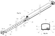
- Figures 1 - 4 show a first embodiment of a LED tubular lamp assembly 1 according to the present invention.
- the tubular lamp assembly 1 is exploded in a longitudinal direction X which is characterized by a double arrow.
- the assembly 1 comprises a tube housing 10, a PCB assembly 20 and two side cap assemblies 30.
- the side cap assemblies 30 are identically designed in this embodiment.
- the tube housing 10 has a cross section as shown in fig. 1b which is circumferentially closed and constant in the longitudinal direction X constant.
- the cross section is almost rectangular with a width W and a height H.
- the width W is slightly greater than the height H.
- the length L in the longitudinal direction X is much greater than both, the Width W and the height H.
- the tube housing 10 has a flat back wall 11, two slightly curved side walls 12 and a slightly curved front wall 13.
- the tube housing 10, in particular the front wall 13 is at least partly light-permeable, i.e. transparent or translucent.
- the back wall does not need to be light-permeable as well.
- Two inner notches 14 extend in the longitudinal direction X at the side walls 12 adjacent the flat back wall 11.
- first outer ribs 15 result at the side walls 12 extending in correspondence with the inner notches 14 in the longitudinal direction as well.
- the flat back wall 11 is further provided with two second outer ribs 16 extending in the longitudinal direction as well.
- the PCB assembly 20 comprises a printed circuit board 21 provided with a plurality of LED-chips 22 arranged in a row.
- the printed circuit board 21 is further provided with electronic devices 23 including at least one integrated circuit for supplying the LED-chips 22 with electric power from a mains supply.
- the PCB assembly 20 is further provided with a pair of flat contact areas 24, respectively.
- Other flat contact areas and tracks on the printed circuit board 21 for electrically connecting the LED-chips 22 and the electronic devices 23 are not shown but should be understood as being provided of course, too.
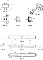
- the side cap assembly 30 is provided with a pair of outer contacts 31 for allowing the LED tubular lamp assembly 1 to be electrically connected to an electric power supply (not shown).
- the outer contacts 31 are in the form of pins projecting outwards in the longitudinal direction X for being compatible with standard sockets such as T5 in particular.
- the side cap assembly 30 is further provided with a pair of inner contacts 32 for electrically connecting the outer contacts 31 to the contact areas 24 on the printed circuit board 21.
- the inner contacts 32 are in the form of spring type sliding contacts.
- the side cap assembly 30 further has a flat wall part 33 in which the outer contacts 31 and the inner contacts 32 are commonly secured and from which projects a tube like section 34 in the longitudinal direction surrounding the inner contacts 32.
- the flat wall part 33 extends beyond the tube like section 34 on all sides thereof for forming a collar 35.
- a tongue 36 projects between the inner contacts 32 as a separating means between such contacts. The tongue also guides the contacts upon their deflection.
- FIG. 1a Different views of the LED tubular lamp assembly 1 of fig. 1a are shown in figures 3a - 3e in the assembled state.
- Figures 4 a - 4e show details of the LED tubular lamp assembly of Fig. 1a as well in the assembled state.
- the PCB assembly 20 is inserted in the longitudinal direction X into the tube housing 10 such that the printed circuit board 21 engages with its outer edges 21a and 21 b the two notches 14.
- the PCB assembly 20 is arranged with only a small lateral tolerance parallel to the flat back wall 11 and even preferably in contact therewith.
- the PCB assembly is of course inserted into the tube housing 10 in an orientation that the light emitted by the LED-chips 22 is mainly emitted in the direction of the front wall 13.
- the two side cap assemblies 30 are as well inserted in the longitudinal direction into the tube housing 10 at both ends thereof.
- the tube like sections 34 are adapted to closely fit into the tube housing 10 such that the end sections thereof are wedged and a press fit is achieved securing the side cap assemblies 30 in the tube housing 10 without the necessity of further means.
- collars 35 becoming flush with the front ends of the tube housing 10 the insertion of the side cap assemblies 30 is restricted to a partial insertion.
- the outer contours of the collars 35 also conform to the outer contour of the cross section of the tube housing 10.
- the inner contacts 32 which are in the form of spring type sliding contacts slidably come into electrical contact with the contact areas of the PCB assembly as this can best be seen from figures 3b and 3d . No further means or procedural steps are required to establish such contact.
- the length of the printed circuit board 21 of the PCB assembly 20 is chosen such that it fits almost exactly between the two side cap assemblies 30 in the tube housing 10. In the assembled state that is shown in figures 4a - 4d the PCB assembly 20 is thereby fixed against displacement in the longitudinal direction in the tube housing 10 by the two side cap assemblies 30.
- Figures 5 and 6 show a second embodiment of a LED tubular lamp assembly 1 according to the present invention. Different from the first embodiment the pins of the first contacts 31 of the side cap assemblies 30 are separated by a greater distance from each other than in the first embodiment. This also applies for the spring type second contacts 32. Thereby contacts 31 are compatible with standard sockets such as T8 in particular.
- the tube like sections 34 of the side cap assemblies 30 are also somewhat different from such sections of the first embodiment as this can be seen by comparing figures 2c - 2e with figures 6c - 6e .
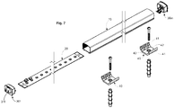
- a third embodiment will now still be explained with reference to figures 7 - 13 .
- the two side cap assemblies are different from each other.
- the outer contacts of one of the side cap assemblies, in fig. 7 designated by 30m are male type outer contacts 31m whereas the outer contacts of the other side cap assembly, in fig. 7 designated by 30f, are female type outer contacts 31f.
- Both, the male 31m and the female type outer contacts 31f are configured to be connected by plugging in the longitudinal direction X.
- LED tubular lamp assemblies according to the first or and second embodiment of the invention that are provided with projecting pin like outer contacts 31 being compatible with common T5 or T8 sockets are inserted as a whole transversely with respect to their longitudinal extension between two such sockets with their projecting pins 31 engaging a slit in a rotatable part of the sockets, respectively.
- the LED tubular lamp assemblies and are then electrically connected as well as mechanically secured by rotation around their longitudinal extension.
- mechanical fixation means may be required in addition to the pluggable electrical contact means.
- Fig. 7 shows the LED tubular lamp assembly according to the third embodiment of the invention together with two mounting brackets 40 as additional mechanical fixation means.
- the mounting brackets 40 have two snap arms 41 for engaging the first outer ribs 15 of the tube housing 10 and a connecting part 42 between the snap arms each.
- a screw hole 43 in the connecting part 42 allows an attachment of the mounting brackets 40 by means of a screw and if necessary a wall plug to a supporting structure.
- Figures 8a - 8e show the LED tubular lamp assembly of fig. 7 in the assembled state together with two mounting brackets 40 snapped onto the tube housing. More details of the brackets 40 can be taken from figures 9a - 9c .
- FIG. 7 Different views of the side cap assembly 30m of fig. 7 having male type outer contacts 31 m are shown in figures 10a - 10e.
- Figures 11a - 11e show different views of the side cap assembly 30f of fig. 7 having female type outer contacts 31f.
- Figures 12a - 12d and 13a - 13d show details of the LED tubular lamp assembly of Fig. 7 in the assembled state.
- the design of the side cap assemblies 30m and 30f of the third embodiment is almost identical and corresponds to the design of the side cap assemblies 30 of the first embodiment.
- the inner contacts 32 are again in the form of spring type sliding contacts here and a tube like section 34 is provided surrounding the inner contacts which is adapted to closely fit into the tube housing 10.
- Both side cap assemblies 30m and 30f are thereby configured to be inserted into the tube housing 10 in the longitudinal direction X and to be secured therein by a press fit.
- the same tubular housing 10 and the same PCB assembly 20 may be used.
- the contact areas 24 on the printed circuit board 21 are designed large enough to match with the respective positions of the inner contacts 32 in each case.
Landscapes
- Engineering & Computer Science (AREA)
- General Engineering & Computer Science (AREA)
- Physics & Mathematics (AREA)
- Microelectronics & Electronic Packaging (AREA)
- Optics & Photonics (AREA)
- Fastening Of Light Sources Or Lamp Holders (AREA)
- Non-Portable Lighting Devices Or Systems Thereof (AREA)
Claims (11)
- Ensemble lampe tubulaire à DEL (1) comprenant :un boîtier de tube (10) qui est au moins partiellement perméable à la lumière et ayant une section transversale qui est circonférentiellement fermée et constante dans une direction longitudinale (X) ;un ensemble PCB (20) prévu avec des zones de contact (24) et des puces de DEL (22) et étant inséré dans le boîtier de tube (10) dans la direction longitudinale (X) ; etdeux ensembles de capuchon latéraux (30 ; 30m, 30f) prévus avec des contacts externes (31 ; 31m, 31f) pour permettre à l'ensemble lampe tubulaire à DEL (1) d'être raccordé électriquement à une alimentation électrique et des contacts internes (32) pour raccorder électriquement les contacts externes (31 ; 31m, 31f) aux zones de contact (24) de l'ensemble PCB (20) et étant au moins partiellement insérés dans le boîtier de tube (10) dans la direction longitudinale (X) ; etdans lequel les contacts internes (32) sont configurés pour venir, de manière coulissante, en contact électrique avec les zones de contact (24) de l'ensemble PCB (20) suite à l'insertion au moins partielle des ensembles de capuchon latéraux (30 ; 30m, 30f) dans le boîtier de tube (10) dans la direction longitudinale (X), dans lequel les contacts internes (32) des ensembles de capuchon latéraux (30) sont des contacts coulissants de type à ressort, dans lequel les contacts coulissants de type à ressort sont séparés les uns des autres et guidés suite à la déviation par une languette (36) faisant saillie entre eux, respectivement, dans lequel les contacts externes (31 ; 31m, 31f) sont formés de manière solidaire avec les contacts internes (32), dans lequel le boîtier de tube (10) a deux encoches internes (14) s'étendant dans la direction longitudinale (X) se faisant face et étant mises en prise par l'ensemble PCB (20), caractérisé en ce que le boîtier de tube (10) a une paroi arrière plate faisant partie de la section transversale presque rectangulaire, les encoches internes (14) étant partiellement formées par la paroi arrière plate de sorte que l'ensemble PCB (20) est en contact avec la paroi arrière plate dans une direction perpendiculaire à la direction longitudinale (X).
- Ensemble lampe tubulaire à DEL (1) selon la revendication 1, dans lequel le boîtier de tube (10) a deux premières nervures externes (15) s'étendant dans la direction longitudinale (X) en correspondance avec les encoches internes (14).
- Ensemble lampe tubulaire à DEL (1) selon la revendication 2, comprenant en outre au moins un support de montage (40) ayant deux bras d'encliquetage (41) pour mettre en prise les premières nervures externes (15) du boîtier de tube (10) et une partie de raccordement (42) entre les bras d'encliquetage (41) pour la fixation de l'ensemble lampe tubulaire à DEL (1) sur une structure de support.
- Ensemble lampe tubulaire à DEL (1) selon l'une des revendications 1 à 3, dans lequel le boîtier de tube (10) a une paroi arrière plate (11) qui est prévue avec des secondes nervures externes (16) s'étendant dans la direction longitudinale (X).
- Ensemble lampe tubulaire à DEL (1) selon l'une des revendications 1 à 4, dans lequel l'ensemble PCB (20) est fixe par rapport au déplacement dans la direction longitudinale (X) dans le boîtier de tube (10) grâce aux deux ensembles de capuchon latéraux (30 ; 30m, 30f).
- Ensemble lampe tubulaire à DEL (1) selon l'une des revendications 1 à 5, dans lequel l'ensemble PCB (20) a des sections d'extrémité (25) pour ce qui est de la direction longitudinale et dans lequel les zones de contact (24) sont des zones plates au niveau de ces sections d'extrémité (25).
- Ensemble lampe tubulaire à DEL (1) selon l'une des revendications 1 à 6, dans lequel les zones de contact (24), les contacts internes (32) et les contacts externes (31 : 31m, 31f) sont respectivement prévus par paire.
- Ensemble lampe tubulaire à DEL (1) selon l'une des revendications 1 à 7, dans lequel l'ensemble PCB (20) est prévu avec des dispositifs électroniques (23) comprenant au moins un circuit intégré pour alimenter les puces de DEL (22) avec l'alimentation électrique provenant d'une alimentation secteur.
- Ensemble lampe tubulaire à DEL (1) selon l'une des revendications 1 à 8, dans lequel les ensembles de capuchon latéraux (30 ; 30m, 30f) sont fixés sur le boîtier de tube (10) par ajustement à la presse dans la direction longitudinale (X).
- Ensemble lampe tubulaire à DEL (1) selon l'une des revendications 1 à 9, dans lequel les contacts externes (31 ; 31m, 31f) des ensembles de capuchon latéraux (30 ; 30m, 30f) comprennent des broches faisant saillie vers l'extérieur dans la direction longitudinale (X).
- Ensemble lampe tubulaire à DEL (1) selon l'une des revendications 1 à 9, dans lequel les contacts externes de l'un des ensembles de capuchon latéraux (30m) sont des contacts externes de type mâle (31m) et dans lequel les contacts externes de l'autre ensemble de capuchon latéral (30f) sont des contacts externes de type femelle (31f), et les contacts externes de type mâle et femelle (31m, 31f) étant configurés pour être respectivement raccordés par branchement dans la direction longitudinale (X).
Applications Claiming Priority (2)
| Application Number | Priority Date | Filing Date | Title |
|---|---|---|---|
| IN3691MU2015 | 2015-09-29 | ||
| PCT/IN2016/050327 WO2017056110A1 (fr) | 2015-09-29 | 2016-09-29 | Ensemble lampe tubulaire à del |
Publications (2)
| Publication Number | Publication Date |
|---|---|
| EP3356733A1 EP3356733A1 (fr) | 2018-08-08 |
| EP3356733B1 true EP3356733B1 (fr) | 2021-11-10 |
Family
ID=57241134
Family Applications (1)
| Application Number | Title | Priority Date | Filing Date |
|---|---|---|---|
| EP16791450.6A Not-in-force EP3356733B1 (fr) | 2015-09-29 | 2016-09-29 | Ensemble lampe tubulaire à del |
Country Status (2)
| Country | Link |
|---|---|
| EP (1) | EP3356733B1 (fr) |
| WO (1) | WO2017056110A1 (fr) |
Families Citing this family (1)
| Publication number | Priority date | Publication date | Assignee | Title |
|---|---|---|---|---|
| CN107477378A (zh) * | 2017-09-07 | 2017-12-15 | 魏再洪 | 具有抽卡结构的led灯具 |
Citations (4)
| Publication number | Priority date | Publication date | Assignee | Title |
|---|---|---|---|---|
| EP2216859A1 (fr) * | 2009-02-06 | 2010-08-11 | Tyco Electronics Corporation | Ensemble de bouchon d'extrémité pour tube lumineux |
| JP2014053219A (ja) * | 2012-09-08 | 2014-03-20 | Iris Ohyama Inc | 直管型ledランプ |
| CN203963553U (zh) * | 2014-04-29 | 2014-11-26 | 鹤山市银雨照明有限公司 | 一种具有折叠式软电路板的led日光灯管 |
| US20150176770A1 (en) * | 2013-12-20 | 2015-06-25 | Cree, Inc. | Led lamp |
Family Cites Families (12)
| Publication number | Priority date | Publication date | Assignee | Title |
|---|---|---|---|---|
| ITTO20030673A1 (it) * | 2003-09-04 | 2005-03-05 | Space Cannon Vh S P A | Barra di luce a led. |
| KR200456665Y1 (ko) * | 2009-03-31 | 2011-11-10 | 인창전자주식회사 | 엘이디등의 엔드 캡 |
| KR100997646B1 (ko) * | 2010-04-02 | 2010-12-01 | 루미리치 주식회사 | 발광다이오드 조명등 |
| US8596813B2 (en) * | 2010-07-12 | 2013-12-03 | Ilumisys, Inc. | Circuit board mount for LED light tube |
| EP2444716B8 (fr) * | 2010-10-19 | 2015-07-29 | Feelux Co., Ltd. | Appareil d'éclairage |
| DE102011050908A1 (de) * | 2011-06-08 | 2012-12-13 | Dietmar Müller | Leuchtdiodenlampe und Schaltung zur Steuerung einer Lichtquelle |
| KR20140051924A (ko) * | 2011-07-14 | 2014-05-02 | 저스팅 테크놀로지 피티이. 리미티드. | 램프 튜브 |
| KR101347256B1 (ko) * | 2012-05-08 | 2014-01-06 | 루미리치 주식회사 | 발광다이오드 조명 장치 |
| TWM448625U (zh) * | 2012-09-07 | 2013-03-11 | High Perfection Technology Co Ltd | 發光二極體燈管接頭、接頭連接器及其組合 |
| WO2014195801A2 (fr) * | 2013-06-05 | 2014-12-11 | Brian Barrett | Système d'éclairage par diode électroluminescente modulaire |
| JP2015046352A (ja) * | 2013-08-29 | 2015-03-12 | 東芝ライテック株式会社 | 直管形ランプおよび照明装置 |
| DE102014202759B4 (de) * | 2014-02-14 | 2025-06-26 | Ledvance Gmbh | Rohr für eine Halbleiter-Röhrenlampe und das Rohr aufweisende Halbleiter-Röhrenlampe |
-
2016
- 2016-09-29 EP EP16791450.6A patent/EP3356733B1/fr not_active Not-in-force
- 2016-09-29 WO PCT/IN2016/050327 patent/WO2017056110A1/fr not_active Ceased
Patent Citations (4)
| Publication number | Priority date | Publication date | Assignee | Title |
|---|---|---|---|---|
| EP2216859A1 (fr) * | 2009-02-06 | 2010-08-11 | Tyco Electronics Corporation | Ensemble de bouchon d'extrémité pour tube lumineux |
| JP2014053219A (ja) * | 2012-09-08 | 2014-03-20 | Iris Ohyama Inc | 直管型ledランプ |
| US20150176770A1 (en) * | 2013-12-20 | 2015-06-25 | Cree, Inc. | Led lamp |
| CN203963553U (zh) * | 2014-04-29 | 2014-11-26 | 鹤山市银雨照明有限公司 | 一种具有折叠式软电路板的led日光灯管 |
Also Published As
| Publication number | Publication date |
|---|---|
| WO2017056110A1 (fr) | 2017-04-06 |
| EP3356733A1 (fr) | 2018-08-08 |
Similar Documents
| Publication | Publication Date | Title |
|---|---|---|
| KR101347256B1 (ko) | 발광다이오드 조명 장치 | |
| US9184518B2 (en) | Electrical connector header for an LED-based light | |
| EP2257730B1 (fr) | Commande de del intégrée pour douille à del | |
| US9696023B2 (en) | Electric connecting member and LED lamp using the same | |
| CN105408684B (zh) | Led照明组件及其制造方法 | |
| EP2843291A1 (fr) | Luminaire et lampe à tube droit | |
| CN101761901A (zh) | 两部分表面安装的led灯条连接器和led组装件 | |
| JP3154200U (ja) | Ledランプ | |
| JP5472635B2 (ja) | 直管形ランプおよび照明器具 | |
| CN203743939U (zh) | 发光模块、管形发光灯以及照明器具 | |
| EP3260770B1 (fr) | Structure de connexion électrique de culot de lampe | |
| US20140247585A1 (en) | Semiconductor lighting apparatus | |
| US9772097B2 (en) | Efficient board to board connection | |
| US7140920B1 (en) | Electric plug | |
| EP2687773A1 (fr) | Structure de lampe à DEL | |
| KR101309237B1 (ko) | 확장연결을 위한 튜브형 led 램프 | |
| EP3356733B1 (fr) | Ensemble lampe tubulaire à del | |
| KR101140162B1 (ko) | 직관형 엘이디 램프 조립체 | |
| US10634319B2 (en) | Strip-shaped LED interconnected high-voltage lamp | |
| US10655798B2 (en) | LED lighting device and method for manufacturing the same | |
| US11774046B2 (en) | LED light source assembly and high-power lamp using the same | |
| TWM506243U (zh) | Led球泡燈 | |
| CN207455231U (zh) | 一种条形led互联高压灯 | |
| WO2015011636A1 (fr) | Support pour lampes à del | |
| CN105870749A (zh) | 转接头、照明装置 |
Legal Events
| Date | Code | Title | Description |
|---|---|---|---|
| STAA | Information on the status of an ep patent application or granted ep patent |
Free format text: STATUS: UNKNOWN |
|
| STAA | Information on the status of an ep patent application or granted ep patent |
Free format text: STATUS: THE INTERNATIONAL PUBLICATION HAS BEEN MADE |
|
| PUAI | Public reference made under article 153(3) epc to a published international application that has entered the european phase |
Free format text: ORIGINAL CODE: 0009012 |
|
| STAA | Information on the status of an ep patent application or granted ep patent |
Free format text: STATUS: REQUEST FOR EXAMINATION WAS MADE |
|
| 17P | Request for examination filed |
Effective date: 20180320 |
|
| AK | Designated contracting states |
Kind code of ref document: A1 Designated state(s): AL AT BE BG CH CY CZ DE DK EE ES FI FR GB GR HR HU IE IS IT LI LT LU LV MC MK MT NL NO PL PT RO RS SE SI SK SM TR |
|
| AX | Request for extension of the european patent |
Extension state: BA ME |
|
| DAV | Request for validation of the european patent (deleted) | ||
| DAX | Request for extension of the european patent (deleted) | ||
| STAA | Information on the status of an ep patent application or granted ep patent |
Free format text: STATUS: EXAMINATION IS IN PROGRESS |
|
| 17Q | First examination report despatched |
Effective date: 20190322 |
|
| GRAP | Despatch of communication of intention to grant a patent |
Free format text: ORIGINAL CODE: EPIDOSNIGR1 |
|
| STAA | Information on the status of an ep patent application or granted ep patent |
Free format text: STATUS: GRANT OF PATENT IS INTENDED |
|
| INTG | Intention to grant announced |
Effective date: 20210708 |
|
| GRAS | Grant fee paid |
Free format text: ORIGINAL CODE: EPIDOSNIGR3 |
|
| GRAA | (expected) grant |
Free format text: ORIGINAL CODE: 0009210 |
|
| STAA | Information on the status of an ep patent application or granted ep patent |
Free format text: STATUS: THE PATENT HAS BEEN GRANTED |
|
| AK | Designated contracting states |
Kind code of ref document: B1 Designated state(s): AL AT BE BG CH CY CZ DE DK EE ES FI FR GB GR HR HU IE IS IT LI LT LU LV MC MK MT NL NO PL PT RO RS SE SI SK SM TR |
|
| REG | Reference to a national code |
Ref country code: GB Ref legal event code: FG4D |
|
| REG | Reference to a national code |
Ref country code: AT Ref legal event code: REF Ref document number: 1446416 Country of ref document: AT Kind code of ref document: T Effective date: 20211115 Ref country code: CH Ref legal event code: EP |
|
| REG | Reference to a national code |
Ref country code: DE Ref legal event code: R096 Ref document number: 602016066077 Country of ref document: DE |
|
| REG | Reference to a national code |
Ref country code: IE Ref legal event code: FG4D |
|
| REG | Reference to a national code |
Ref country code: LT Ref legal event code: MG9D |
|
| REG | Reference to a national code |
Ref country code: NL Ref legal event code: MP Effective date: 20211110 |
|
| REG | Reference to a national code |
Ref country code: AT Ref legal event code: MK05 Ref document number: 1446416 Country of ref document: AT Kind code of ref document: T Effective date: 20211110 |
|
| PG25 | Lapsed in a contracting state [announced via postgrant information from national office to epo] |
Ref country code: RS Free format text: LAPSE BECAUSE OF FAILURE TO SUBMIT A TRANSLATION OF THE DESCRIPTION OR TO PAY THE FEE WITHIN THE PRESCRIBED TIME-LIMIT Effective date: 20211110 Ref country code: LT Free format text: LAPSE BECAUSE OF FAILURE TO SUBMIT A TRANSLATION OF THE DESCRIPTION OR TO PAY THE FEE WITHIN THE PRESCRIBED TIME-LIMIT Effective date: 20211110 Ref country code: FI Free format text: LAPSE BECAUSE OF FAILURE TO SUBMIT A TRANSLATION OF THE DESCRIPTION OR TO PAY THE FEE WITHIN THE PRESCRIBED TIME-LIMIT Effective date: 20211110 Ref country code: BG Free format text: LAPSE BECAUSE OF FAILURE TO SUBMIT A TRANSLATION OF THE DESCRIPTION OR TO PAY THE FEE WITHIN THE PRESCRIBED TIME-LIMIT Effective date: 20220210 Ref country code: AT Free format text: LAPSE BECAUSE OF FAILURE TO SUBMIT A TRANSLATION OF THE DESCRIPTION OR TO PAY THE FEE WITHIN THE PRESCRIBED TIME-LIMIT Effective date: 20211110 |
|
| PG25 | Lapsed in a contracting state [announced via postgrant information from national office to epo] |
Ref country code: IS Free format text: LAPSE BECAUSE OF FAILURE TO SUBMIT A TRANSLATION OF THE DESCRIPTION OR TO PAY THE FEE WITHIN THE PRESCRIBED TIME-LIMIT Effective date: 20220310 Ref country code: SE Free format text: LAPSE BECAUSE OF FAILURE TO SUBMIT A TRANSLATION OF THE DESCRIPTION OR TO PAY THE FEE WITHIN THE PRESCRIBED TIME-LIMIT Effective date: 20211110 Ref country code: PT Free format text: LAPSE BECAUSE OF FAILURE TO SUBMIT A TRANSLATION OF THE DESCRIPTION OR TO PAY THE FEE WITHIN THE PRESCRIBED TIME-LIMIT Effective date: 20220310 Ref country code: PL Free format text: LAPSE BECAUSE OF FAILURE TO SUBMIT A TRANSLATION OF THE DESCRIPTION OR TO PAY THE FEE WITHIN THE PRESCRIBED TIME-LIMIT Effective date: 20211110 Ref country code: NO Free format text: LAPSE BECAUSE OF FAILURE TO SUBMIT A TRANSLATION OF THE DESCRIPTION OR TO PAY THE FEE WITHIN THE PRESCRIBED TIME-LIMIT Effective date: 20220210 Ref country code: NL Free format text: LAPSE BECAUSE OF FAILURE TO SUBMIT A TRANSLATION OF THE DESCRIPTION OR TO PAY THE FEE WITHIN THE PRESCRIBED TIME-LIMIT Effective date: 20211110 Ref country code: LV Free format text: LAPSE BECAUSE OF FAILURE TO SUBMIT A TRANSLATION OF THE DESCRIPTION OR TO PAY THE FEE WITHIN THE PRESCRIBED TIME-LIMIT Effective date: 20211110 Ref country code: HR Free format text: LAPSE BECAUSE OF FAILURE TO SUBMIT A TRANSLATION OF THE DESCRIPTION OR TO PAY THE FEE WITHIN THE PRESCRIBED TIME-LIMIT Effective date: 20211110 Ref country code: GR Free format text: LAPSE BECAUSE OF FAILURE TO SUBMIT A TRANSLATION OF THE DESCRIPTION OR TO PAY THE FEE WITHIN THE PRESCRIBED TIME-LIMIT Effective date: 20220211 Ref country code: ES Free format text: LAPSE BECAUSE OF FAILURE TO SUBMIT A TRANSLATION OF THE DESCRIPTION OR TO PAY THE FEE WITHIN THE PRESCRIBED TIME-LIMIT Effective date: 20211110 |
|
| PG25 | Lapsed in a contracting state [announced via postgrant information from national office to epo] |
Ref country code: SM Free format text: LAPSE BECAUSE OF FAILURE TO SUBMIT A TRANSLATION OF THE DESCRIPTION OR TO PAY THE FEE WITHIN THE PRESCRIBED TIME-LIMIT Effective date: 20211110 Ref country code: SK Free format text: LAPSE BECAUSE OF FAILURE TO SUBMIT A TRANSLATION OF THE DESCRIPTION OR TO PAY THE FEE WITHIN THE PRESCRIBED TIME-LIMIT Effective date: 20211110 Ref country code: RO Free format text: LAPSE BECAUSE OF FAILURE TO SUBMIT A TRANSLATION OF THE DESCRIPTION OR TO PAY THE FEE WITHIN THE PRESCRIBED TIME-LIMIT Effective date: 20211110 Ref country code: EE Free format text: LAPSE BECAUSE OF FAILURE TO SUBMIT A TRANSLATION OF THE DESCRIPTION OR TO PAY THE FEE WITHIN THE PRESCRIBED TIME-LIMIT Effective date: 20211110 Ref country code: DK Free format text: LAPSE BECAUSE OF FAILURE TO SUBMIT A TRANSLATION OF THE DESCRIPTION OR TO PAY THE FEE WITHIN THE PRESCRIBED TIME-LIMIT Effective date: 20211110 Ref country code: CZ Free format text: LAPSE BECAUSE OF FAILURE TO SUBMIT A TRANSLATION OF THE DESCRIPTION OR TO PAY THE FEE WITHIN THE PRESCRIBED TIME-LIMIT Effective date: 20211110 |
|
| REG | Reference to a national code |
Ref country code: DE Ref legal event code: R097 Ref document number: 602016066077 Country of ref document: DE |
|
| PLBE | No opposition filed within time limit |
Free format text: ORIGINAL CODE: 0009261 |
|
| STAA | Information on the status of an ep patent application or granted ep patent |
Free format text: STATUS: NO OPPOSITION FILED WITHIN TIME LIMIT |
|
| 26N | No opposition filed |
Effective date: 20220811 |
|
| PG25 | Lapsed in a contracting state [announced via postgrant information from national office to epo] |
Ref country code: AL Free format text: LAPSE BECAUSE OF FAILURE TO SUBMIT A TRANSLATION OF THE DESCRIPTION OR TO PAY THE FEE WITHIN THE PRESCRIBED TIME-LIMIT Effective date: 20211110 |
|
| PG25 | Lapsed in a contracting state [announced via postgrant information from national office to epo] |
Ref country code: SI Free format text: LAPSE BECAUSE OF FAILURE TO SUBMIT A TRANSLATION OF THE DESCRIPTION OR TO PAY THE FEE WITHIN THE PRESCRIBED TIME-LIMIT Effective date: 20211110 |
|
| REG | Reference to a national code |
Ref country code: DE Ref legal event code: R119 Ref document number: 602016066077 Country of ref document: DE |
|
| PG25 | Lapsed in a contracting state [announced via postgrant information from national office to epo] |
Ref country code: MC Free format text: LAPSE BECAUSE OF FAILURE TO SUBMIT A TRANSLATION OF THE DESCRIPTION OR TO PAY THE FEE WITHIN THE PRESCRIBED TIME-LIMIT Effective date: 20211110 |
|
| REG | Reference to a national code |
Ref country code: CH Ref legal event code: PL |
|
| GBPC | Gb: european patent ceased through non-payment of renewal fee |
Effective date: 20220929 |
|
| REG | Reference to a national code |
Ref country code: BE Ref legal event code: MM Effective date: 20220930 |
|
| PG25 | Lapsed in a contracting state [announced via postgrant information from national office to epo] |
Ref country code: IT Free format text: LAPSE BECAUSE OF FAILURE TO SUBMIT A TRANSLATION OF THE DESCRIPTION OR TO PAY THE FEE WITHIN THE PRESCRIBED TIME-LIMIT Effective date: 20211110 |
|
| PG25 | Lapsed in a contracting state [announced via postgrant information from national office to epo] |
Ref country code: LU Free format text: LAPSE BECAUSE OF NON-PAYMENT OF DUE FEES Effective date: 20220929 |
|
| PG25 | Lapsed in a contracting state [announced via postgrant information from national office to epo] |
Ref country code: LI Free format text: LAPSE BECAUSE OF NON-PAYMENT OF DUE FEES Effective date: 20220930 Ref country code: IE Free format text: LAPSE BECAUSE OF NON-PAYMENT OF DUE FEES Effective date: 20220929 Ref country code: FR Free format text: LAPSE BECAUSE OF NON-PAYMENT OF DUE FEES Effective date: 20220930 Ref country code: DE Free format text: LAPSE BECAUSE OF NON-PAYMENT OF DUE FEES Effective date: 20230401 Ref country code: CH Free format text: LAPSE BECAUSE OF NON-PAYMENT OF DUE FEES Effective date: 20220930 |
|
| PG25 | Lapsed in a contracting state [announced via postgrant information from national office to epo] |
Ref country code: BE Free format text: LAPSE BECAUSE OF NON-PAYMENT OF DUE FEES Effective date: 20220930 |
|
| PG25 | Lapsed in a contracting state [announced via postgrant information from national office to epo] |
Ref country code: GB Free format text: LAPSE BECAUSE OF NON-PAYMENT OF DUE FEES Effective date: 20220929 |
|
| PG25 | Lapsed in a contracting state [announced via postgrant information from national office to epo] |
Ref country code: HU Free format text: LAPSE BECAUSE OF FAILURE TO SUBMIT A TRANSLATION OF THE DESCRIPTION OR TO PAY THE FEE WITHIN THE PRESCRIBED TIME-LIMIT; INVALID AB INITIO Effective date: 20160929 |
|
| PG25 | Lapsed in a contracting state [announced via postgrant information from national office to epo] |
Ref country code: CY Free format text: LAPSE BECAUSE OF FAILURE TO SUBMIT A TRANSLATION OF THE DESCRIPTION OR TO PAY THE FEE WITHIN THE PRESCRIBED TIME-LIMIT Effective date: 20211110 |
|
| PG25 | Lapsed in a contracting state [announced via postgrant information from national office to epo] |
Ref country code: MK Free format text: LAPSE BECAUSE OF FAILURE TO SUBMIT A TRANSLATION OF THE DESCRIPTION OR TO PAY THE FEE WITHIN THE PRESCRIBED TIME-LIMIT Effective date: 20211110 |
|
| PG25 | Lapsed in a contracting state [announced via postgrant information from national office to epo] |
Ref country code: MT Free format text: LAPSE BECAUSE OF FAILURE TO SUBMIT A TRANSLATION OF THE DESCRIPTION OR TO PAY THE FEE WITHIN THE PRESCRIBED TIME-LIMIT Effective date: 20211110 |
|
| PG25 | Lapsed in a contracting state [announced via postgrant information from national office to epo] |
Ref country code: TR Free format text: LAPSE BECAUSE OF FAILURE TO SUBMIT A TRANSLATION OF THE DESCRIPTION OR TO PAY THE FEE WITHIN THE PRESCRIBED TIME-LIMIT Effective date: 20211110 |