EP3357314A1 - Kupplungsvorrichtung für ein landwirtschaftliches arbeitsgerät - Google Patents
Kupplungsvorrichtung für ein landwirtschaftliches arbeitsgerät Download PDFInfo
- Publication number
- EP3357314A1 EP3357314A1 EP18401009.8A EP18401009A EP3357314A1 EP 3357314 A1 EP3357314 A1 EP 3357314A1 EP 18401009 A EP18401009 A EP 18401009A EP 3357314 A1 EP3357314 A1 EP 3357314A1
- Authority
- EP
- European Patent Office
- Prior art keywords
- coupling
- locking
- securing
- coupling device
- agricultural implement
- Prior art date
- Legal status (The legal status is an assumption and is not a legal conclusion. Google has not performed a legal analysis and makes no representation as to the accuracy of the status listed.)
- Granted
Links
Images


Classifications
-
- A—HUMAN NECESSITIES
- A01—AGRICULTURE; FORESTRY; ANIMAL HUSBANDRY; HUNTING; TRAPPING; FISHING
- A01B—SOIL WORKING IN AGRICULTURE OR FORESTRY; PARTS, DETAILS, OR ACCESSORIES OF AGRICULTURAL MACHINES OR IMPLEMENTS, IN GENERAL
- A01B59/00—Devices specially adapted for connection between animals or tractors and agricultural machines or implements
- A01B59/002—Details, component parts
- A01B59/006—Latched hooks
-
- A—HUMAN NECESSITIES
- A01—AGRICULTURE; FORESTRY; ANIMAL HUSBANDRY; HUNTING; TRAPPING; FISHING
- A01B—SOIL WORKING IN AGRICULTURE OR FORESTRY; PARTS, DETAILS, OR ACCESSORIES OF AGRICULTURAL MACHINES OR IMPLEMENTS, IN GENERAL
- A01B59/00—Devices specially adapted for connection between animals or tractors and agricultural machines or implements
- A01B59/06—Devices specially adapted for connection between animals or tractors and agricultural machines or implements for machines mounted on tractors
- A01B59/066—Devices specially adapted for connection between animals or tractors and agricultural machines or implements for machines mounted on tractors of the type comprising at least two lower arms and one upper arm generally arranged in a triangle, e.g. three-point hitches
-
- A—HUMAN NECESSITIES
- A01—AGRICULTURE; FORESTRY; ANIMAL HUSBANDRY; HUNTING; TRAPPING; FISHING
- A01B—SOIL WORKING IN AGRICULTURE OR FORESTRY; PARTS, DETAILS, OR ACCESSORIES OF AGRICULTURAL MACHINES OR IMPLEMENTS, IN GENERAL
- A01B51/00—Undercarriages specially adapted for mounting on various kinds of agricultural tools or apparatus
- A01B51/04—Undercarriages specially adapted for mounting on various kinds of agricultural tools or apparatus drawn by animal or tractor
-
- A—HUMAN NECESSITIES
- A01—AGRICULTURE; FORESTRY; ANIMAL HUSBANDRY; HUNTING; TRAPPING; FISHING
- A01M—CATCHING, TRAPPING OR SCARING OF ANIMALS; APPARATUS FOR THE DESTRUCTION OF NOXIOUS ANIMALS OR NOXIOUS PLANTS
- A01M7/00—Special adaptations or arrangements of liquid-spraying apparatus for purposes covered by this subclass
- A01M7/0082—Undercarriages, frames, mountings, couplings, tanks
Definitions
- the invention relates to a coupling device for an agricultural implement according to the preamble of patent claim 1 and an agricultural implement according to the preamble of claim 20.
- Generic coupling devices usually have a coupling element which is adapted to be coupled to a top link of a three-point coupling of a tractor.
- coupling devices are known whose coupling element is designed as a bolt, wherein the coupling of the upper link to the bolt is effected by means of a catch hook attached to the upper link.
- coupling devices In order to provide the operator with a larger space for carrying out the connection work, coupling devices have been developed in which the coupling element between a dome position and a working position is movable. In the dome position, the machine operator has more space between the tractor and the agricultural implement available than in the working position, so that the necessary connection work can be carried out with less effort. After completing the connection work, the distance between the tractor and the agricultural implement are then reduced, whereby the coupling element is moved to the working position.
- the object underlying the invention is therefore to simplify the coupling process of an agricultural implement, which has a movable coupling element, with a tractor.
- a coupling device of the aforementioned type wherein the securing device, which locks the coupling element in the working position together with a locking device located in a locking position, independently of a movement of the agricultural implement from a passive position into the securing position is.
- a load-bearing lock means a lock which is suitable and intended for the proper operation of the agricultural implement to which the coupling device is fastened.
- the resilient lock can not be solved or relaxed by forces that usually occur during operation of the agricultural implement.
- the invention takes advantage of the finding that the lack of movement of the agricultural implement to complete the locking operation greatly simplifies the coupling of the agricultural implement. In particular, it is not necessary to raise the agricultural implement to complete the locking operation. In principle, however, it is conceivable that the agricultural implement is still raised during the locking process, for example, to spend the agricultural implement in an operating position. However, the coupling device according to the invention requires this movement of the agricultural implement but not necessarily to complete the locking operation.
- the coupling element is pivotally hinged to one or more pivoting levers.
- a pivot lever pair extends from the coupling element upwards, wherein the pair of pivot lever is articulated above the coupling element via a connecting shaft to a further pivot lever.
- the further pivoting lever extends downwardly from the connecting shaft and is articulated below the coupling element on the machine frame of the agricultural implement.
- the coupling element is freely movable or not detected in the coupling position, so that it can be deflected out of the coupling position.
- the coupling element comprises the upper coupling point of the three-point coupling, wherein the three-point coupling may be a three-point linkage.
- the coupling element is designed as a bolt so that a catch hook attached to the top link of the three-point coupling can be brought into engagement with the coupling element.
- the coupling device preferably additionally comprises two lower coupling devices, which are arranged below the coupling element.
- the two lower coupling devices preferably comprise the lower coupling points of the three-point coupling.
- the securing device can be moved manually from the passive position into the securing position. Due to the fact that the securing device can be moved manually from the passive position into the securing position, the final locking of the coupling element can be carried out by the machine operator himself. In contrast to automatically locking locking systems, the dependence of the locking process on a triggering event, such as a lifting of the agricultural implement, is overcome.
- the coupling device according to the invention is also advantageously further developed in that the locking device comprises at least one, preferably two pivotable locking pawls.
- the two locking pawls are preferably spaced from each other, the two locking pawls having a substantially identical basic shape.
- the securing device comprises at least one, preferably two pivotable securing pawls.
- the two safety pawls are preferably arranged at a distance from each other, wherein the two safety pawls have a substantially identical basic shape.
- the pivot axis of the two locking pawls and the pivot axis of the two securing pawls are preferably spaced apart from each other and extend substantially parallel to each other.
- the locking system preferably has a receiving device for the coupling element, wherein the receiving device is fixedly attached to the machine frame and / or has a guide slot for the coupling element.
- the receiving device preferably has two spaced apart and / or substantially identically formed flat receiving body.
- the guide slot extends over a portion of the path of movement of the coupling element from the dome position to the working position.
- the guide slot on a stop, wherein the stop of the guide slot, the movement of the coupling element in the Tractors facing away direction limited.
- the coupling element is in an intermediate position when the coupling element bears against the stop of the guide slot.
- the locking device also has a stop, wherein the stop of the locking device limits the movement of the coupling element in the direction of the tractor.
- the coupling element is in the working position when the coupling element rests against the stop of the locking device.
- the locking system comprises an actuating element, by means of which the securing device between the passive position and the securing position is movable.
- the actuating element can be actuated manually and preferably have a manually operable actuating lever.
- the actuating element may comprise one or more electrically, hydraulically or pneumatically driven actuators, by means of which the securing device is movable between the passive position and the securing position.
- an electric actuator may be formed as a linear motor.
- the locking system has a display which indicates the state of the securing device or of the locking system.
- the display comprises optically perceptible characters, by means of which the current state of the securing device or of the locking system can be derived from the position of an actuating lever.
- the state of the securing device or the locking system can be detected by a suitable sensor and displayed to the driver of the tractor, for example by means of a display.
- the securing device is coupled to a storage device of the agricultural implement.
- Agricultural implements often have one Shutdown on so that the agricultural implement can be parked without tipping over and / or without the risk of damage, for example, on the floor of a machine shop or on the field.
- the storage device must always be transferred from a AbstellMap to a working state before using the agricultural implement, such coupling offers itself in a special way, since the safety device must also undergo a change in state before using the agricultural implement, namely, the safety device of to move the passive position to the securing position.
- the coupling device according to the invention is further developed advantageous in that the storage device has at least one parking support and the securing device is coupled to the parking device such that when moving the parking support from a parking position to a working position, the securing device is moved from the passive position to the securing position.
- the parking support is in the parking position preferably in an extended state, so that the state of the agricultural implement is stabilized.
- the parking support In the working position, the parking support is preferably in a retracted state, whereby a sufficiently large space below the agricultural implement for the proper and safe operation of the agricultural implement is provided. In the retracted state of the jack stand, the risk of plant components getting caught in the agricultural implement is also reduced.
- the agricultural implement is designed as a sprayer, is further avoided by the retraction of the parking support that the parking support protrudes into the spray cone of one or more nozzles.
- the securing device is mechanically connected via one or more levers to the parking device.
- a movement causes the Abstell 1 the storage device or the movement of a connected to the parking support member movement of the one or more levers.
- the levers effect at least one transformation of the movement type, so that, for example, a linear movement is converted into a rotational movement, so that the securing device can absorb this rotational movement for converting a pivoting movement from the passive position into the securing position.
- a coupling device is preferred in which the locking device is temporarily moved when moving the coupling element from the dome position to the working position in a release position in which the locking device releases the path of movement for the coupling element of the dome position and the working position.
- the coupling element can be moved, for example, by a reversing of the tractor from the dome position and the working position.
- the locking device is temporarily brought into a release position, that the coupling element when moving from the dome position to the working position with the outer contour of the locking device comes into contact and acted upon by a deflection force. Due to the effective direction of the deflection force, which is predetermined in particular by the outer contour of the locking device, the locking device is pivoted by the contact with the coupling element upwards.
- the locking device is moved by gravity from the release position to the locking position. This is achieved in particular by the fact that the locking device is mounted freely pivotable. Due to the freely pivotable mounting of the locking device, the locking device automatically falls down as soon as the coupling element leaves a predetermined portion of the movement path from the coupling position to the working position.
- a coupling device in which the coupling element is temporarily moved when moving from the working position to the coupling position in an intermediate position, whereby the locking device can be moved from the locking position to the release position.
- the movement of the locking device from the locking position to the release position is necessary during the uncoupling operation of the agricultural implement.
- the locking device can not be brought from the locking position into the release position when the coupling element is in the working position. If the agricultural implement is turned off, the coupling element can be brought into the intermediate position, for example by a reverse drive of the tractor.
- the locking device for moving the coupling element from the working position back to the coupling position is to be held at least temporarily in the release position. If the locking device were not kept in the release position, this would move back to the locking position due to gravity, whereby the uncoupling of agricultural implement is prevented. For example, holding the locking device in the release position manually by the leader of the tractor, in particular by means of a rope.
- the locking system has a holding device which automatically holds the locking device at least temporarily in the release position, while the coupling element is moved from the working position back to the dome position.
- the holding device By the holding device, the need to hold the locking device manually in the release position, overcome, so that even aids, such as a rope, can be dispensed with.
- the use of a rope for holding the locking device causes a considerable risk of damage to the Tractor and the agricultural implement, since the rope is usually operated from the cab of the tractor. In practical use, the rope can get caught unnoticed by the leader of the tractor with a machine part. If the cable is put under tension, even at low forces, electronic or fluidic components can be damaged. This risk of damage is eliminated by the holding device.
- the holding device comprises a prestressable spring element which is adapted to move the locking device from the locking position to the release position when the coupling element is in the intermediate position.
- the spring element is in the prestressed state before the coupling element is moved to the intermediate position. If the coupling element is then moved from the working position to the intermediate position, whereby the locking device is released, the locking device is automatically moved by means of the bias of the spring element from the locking position to the release position. Preferably, the locking device is then held by the holding device in the release position.
- the spring element by means of an actuating element can be prestressed, by means of which preferably also the securing means between the passive position and the securing position is movable.
- the actuating element can be actuated manually and preferably have a manually operable actuating lever.
- the actuating element may comprise one or more actuators driven electrically, hydraulically or pneumatically, by means of which the spring element can be prestressed.
- an electric actuator may be formed as a linear motor.
- the coupling device according to the invention is also advantageously further developed in that the spring element with a storage device of the agricultural implement is coupled. Since the storage device always has to be transferred from a working condition to a stored condition after use of the agricultural implement, such a coupling is particularly suitable since the condition of the spring element must also undergo a change of state after use of the agricultural implement.
- the spring element is to be pretensioned after use of the agricultural implement so that during the uncoupling operation, the locking device can be moved by the spring element from the locking position to the release position.
- the storage device has at least one parking support and the spring element is coupled to the parking device such that when moving the parking support from a working position into a parking position, the spring element is biased.
- the parking support is in the working position preferably in a retracted state, whereby a sufficiently large space below the agricultural implement for the proper and safe operation of the agricultural implement is provided. In the retracted state of the jack stand, the risk of plant components getting caught in the agricultural implement is also reduced. If the agricultural implement is designed as a sprayer, is further avoided by the retraction of the parking support that the parking support protrudes into the spray cone of one or more nozzles. In addition, there is an improved weight distribution during use of the agricultural implement. In the parking position, the parking support is preferably in an extended state, so that the state of the agricultural implement is stabilized.
- the spring element is on the locking device and on a lever hinged.
- the spring element can be biased by shortening the distance of the articulation points of the spring element on the locking device and on the lever. This is preferably done by rotating a shaft to which the lever is attached. If a further rotational movement of the shaft is prevented, the bias of the spring element can be maintained until the locking device is moved to the intermediate position and thus can be pivoted by the spring element.
- the spring element is designed as a gas pressure spring.
- the spring element may also comprise a gas spring.
- Gas springs have sufficient rigidity and are insensitive to external influences. They are therefore particularly suited for use with the present invention.
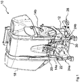
- the Fig. 1 shows an agricultural implement 10, which is designed as a distribution device, namely as a crop protection syringe.
- the agricultural implement 10 has a machine frame 12 having a plurality of interconnected struts, including two vertical struts 14a, 14b and a cross strut 16 disposed between the vertical struts 14a, 14b.
- a liquid tank 18 is attached to the storage of pesticides.
- a coupling device 20 is bolted to the cross member 16.
- the coupling device 20 is for coupling the agricultural implement 10 to a three-point hitch of a tractor such as a tractor.
- the coupling device 20 comprises a coupling element 22, two lower coupling devices 24a, 24b and a locking system 26.
- the coupling element 22 is designed as a bolt and comprises the upper coupling point of the three-point coupling. Further, the coupling element 22 is movable between a dome position and a working position and is adapted to be coupled to a top link of a three-point clutch of a tractor. The top link may for example have a catch hook.
- the two lower coupling devices 24a, 24b are arranged below the coupling element 22 and comprise the lower coupling points of the three-point coupling.
- the locking system 26 is adapted to lock the coupling element 22 in the working position resiliently.
- the locking system 26 is also coupled via a lever mechanism 30 with a storage device 28 of the agricultural implement 10.
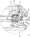
- the Fig. 2 and the Fig. 3 show that the coupling element 22 is pivotally hinged to pivot levers 32a, 32b, wherein the pivot lever 32a, 32b are connected above the coupling element 22 via a connecting shaft with another pivot lever 32c.
- the pivot lever 32c extends from the connecting shaft to below the coupling element 22 and is hinged to the machine frame.
- the coupling element 22 is in the illustrated state of the coupling device 20 in the coupling position.
- the Coupling element 22 is articulated freely movable in the direction of the machine frame of the agricultural implement and thus also in the direction of the working position.
- the locking system 26 comprises a receiving device 34a, 34b, a movable locking device 36a, 36b and a movable securing device 38a, 38b.
- the receiving device 34a, 34b is screwed tightly to the transverse strut 16 and has a guide slot 50a, 50b for the coupling element 22.
- the receiving device 34a, 34b has two spaced apart and substantially identically formed flat receiving body 34a, 34b.
- the guide slot 50a, 50b extends over a portion of the movement path of the coupling element 22 from the dome position to the working position.
- the locking device 36a, 36b comprises two pivotable locking pawls 36a, 36b and is pivotable about a pivot axis 64 between a locking position and a release position, wherein the locking device 36a, 36b is adapted, in the locking position, the movement of the in the working position coupling element 22 in the direction to limit the tractor.
- the locking device 36a, 36b In the illustrated state of the coupling device 20, the locking device 36a, 36b is in the locking position. However, since the coupling element 22 is in the coupling position, the movement of the coupling element 22 is not limited by the locking device 36 a, 36 b.
- the securing device 38a, 38b comprises two pivotable securing pawls and is pivotable about a pivot axis 66 between a securing position and a passive position, the securing device 38a, 38b being arranged in a securing position together with the locking device 36a, 36b in the locking position, the coupling element 22nd To lock in the working position resiliently.
- points the locking device 36a, 36b has a recess 68 through which the pivot pin of the securing device 38a, 38b extends.
- the inner contour of the recess 68 serves as a stop surface and prevented by coming into contact with the pivot pin of the securing device 38a, 38b, a pivoting of the locking device 36a, 36b on the locking position addition.
- the securing device 38a, 38b is in the passive position.
- the securing device 38a, 38b can be moved manually from the passive position into the securing position, so that the securing device 38a, 38b can basically be moved from the passive position into the securing position independently of a movement of the agricultural implement 10.
- the locking system 26 further comprises an actuating element 48, wherein the actuating element 48 has a manually operable actuating lever.
- the securing device 38a, 38b is coupled via a lever mechanism 30 to a parking device 28 of the agricultural implement.
- the storage device 28 has two Abstell Wafer 100a, 52b, which can be extended to stabilize the state of agricultural implement in a parking position.
- the securing device 38a, 38b is coupled via the lever mechanism 30 to the parking device 28 such that when the parking stands are moved from the parking position into a working position, the securing device 38a, 38b is moved from the passive position into the securing position.
- the upper link of a three-point clutch of a tractor for example by means of a catch hook, are brought into engagement with the coupling element 22 in the dome position.
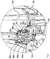
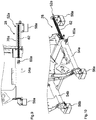
- the Fig. 4 and the Fig. 5 show a state of the coupling device 20, which is achieved by a reset of the tractor, when the upper link of the three-point clutch has been brought into engagement with the coupling element 22 before the tractor is reset.
- the coupling element 22 is moved by the reset of the tractor from the dome position to the working position.
- the locking device 36a, 36b is temporarily pivoted upward during movement of the coupling element 22 along the path of movement from the dome position to the working position and thus brought into the release position, in which the locking device 36a, 36b, the path of movement for the coupling element 22 of the dome position and the working position releases.
- the locking device 36a, 36b is thereby temporarily brought into a release position, that the coupling element 22 comes when moving from the dome position to the working position with the outer contour of the locking device 36a, 36b into contact and thereby the locking device 36a, 36b applied with a deflection force. Due to the deflection force, the locking device 36a, 36b is pivoted about the pivot axis 64 upwards.
- the locking device 36a, 36b is again pivoted by the action of gravity about the pivot axis 64 from the release position back into the locking position. If the locking device 36a, 36b is pivoted back into the locking position by the action of gravity, the coupling element can be brought into its working position by abutment of the tractor again to bear against the inner contour of a hook section 70 of the locking device 36a, 36b.
- the securing device 38a, 38b In the illustrated state of the coupling device 20, the securing device 38a, 38b is in the passive position, so that the coupling element 22 between the hook portion 70 of the locking device 36a, 36b and the rear stop of the guide slots 50a, 50b of the receiving device 34a, 34b is movable.
- the Fig. 6 and the Fig. 7 show a state of the coupling device 20, which is achieved by operating the lever mechanism 30, wherein the lever mechanism 30 is coupled via intermediate members 72, 74 with the securing device 38 a, 38 b.
- the securing device 38a, 38b can thus be moved from the passive position into the securing position independently of a movement of the agricultural implement.
- the securing device 38a, 38b In the illustrated state of the coupling device 20, the securing device 38a, 38b is thus in the securing position.
- the securing device 38a, 38b in a securing position together with the locking device 36a, 36b located in the locking position, effects a loadable locking of the coupling element 22 in the working position, so that the coupling process is completed.
- the coupling element 22 is temporarily moved to an intermediate position after the securing device 38a, 38b has been pivoted from the securing position back into the passive position. Because the coupling element 22 has been brought into an intermediate position, the locking device 36a, 36b can be pivoted from the locking position into the release position. The movement of the coupling element 22 in the intermediate position can be achieved by reversing the tractor, when the agricultural implement is turned off.
- the locking system 26 For pivoting the locking device 36a, 36b from the locking position into the release position, the locking system 26 comprises a holding device 40.
- the holding device 40 comprises a pretensionable spring element 42 which is adapted to move the locking device 36a, 36b from the locking position to the release position when the coupling element 22 is in the intermediate position.
- the spring element 42 is designed as a gas pressure spring and connected via a lever 44 with a shaft 46.
- the bias of the spring element 42 can manually by means of Actuator 48 carried, wherein the actuating element 48 is connected to the shaft 46.
- the spring element 42 may also be coupled to a storage device of the agricultural implement, whereby the biasing of the spring element 42 can also take place via the storage device.
- the locking device 36a, 36b is to hold the coupling element 22 from the working position back to the dome position in the release position, so that the movement path of the coupling element 22 is released from the working position back to the dome position.
- the holding device 40 automatically holds the locking device 36a, 36b in the release position, while the coupling element 22 is moved from the working position back to the dome position.
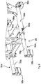
- the 8 to 12 show a storage device 28 of an agricultural implement.
- the agricultural implement can be parked without tipping over and / or without the risk of damage, for example, on the floor of a machine shop or in the field.
- the parking supports 52a, 52b can be extended from a parking position to a working position.
- the securing device 38a, 38b of a locking system 26 of a coupling device 20 may be coupled to such a parking device 28 such that upon movement of the Abstell Northn 52 a, 52 b from the parking position into a working position, the securing device 38 a, 38 b is moved from the passive position to the securing position.
- a spring element 42 of a holding device 40 of a coupling device 20 may be coupled to such a shut-off device 28 that when moving the Abstell Se 52a, 52b from a working position into a parking position, the spring element 42 is biased.
- the storage device 28 has two guide elements 54a, 54b formed as pipe sections, wherein the guide elements 54a, 54b in Aligned substantially parallel to each other and spaced from each other.
- the sliding elements 76a, 76b of the parking supports 52a, 52b which are likewise constructed as pipe sections, are displaceably mounted.
- Abstellforese 56a, 56b, 58a, 58b are arranged on the guide elements 54a, 54b and on the sliding elements 76a, 76b.
- a respective spring element 62 is arranged, which is designed as a helical spring.
- the spring members 62 are each secured by a locking bolt 60a, 60b.
- the parking supports 28a, 28b can each be fixed in the parking position.
- the locking bolts 60a, 60b also serve as fixing elements, which fix the parking supports 28a, 28b in the working position.
Landscapes
- Life Sciences & Earth Sciences (AREA)
- Zoology (AREA)
- Engineering & Computer Science (AREA)
- Mechanical Engineering (AREA)
- Soil Sciences (AREA)
- Environmental Sciences (AREA)
- Agricultural Machines (AREA)
Abstract
Description
- Die Erfindung betrifft eine Kupplungsvorrichtung für ein landwirtschaftliches Arbeitsgerät nach dem Oberbegriff des Patentanspruchs 1 und ein landwirtschaftliches Arbeitsgerät nach dem Oberbegriff des Patentanspruchs 20.
- Gattungsgemäße Kupplungsvorrichtungen weisen üblicherweise ein Koppelelement auf, welches dazu eingerichtet ist, mit einem Oberlenker einer Dreipunkt-Kupplung einer Zugmaschine gekoppelt zu werden. Bekannt sind beispielsweise Kupplungsvorrichtungen, deren Koppelelement als Bolzen ausgebildet ist, wobei die Kopplung des Oberlenkers mit dem Bolzen mittels eines am Oberlenker befestigten Fanghakens erfolgt.
- In der Druckschrift
AT 255 179 B - Bei der Kopplung von landwirtschaftlichen Arbeitsgeräten mit einer Zugmaschine besteht häufig die Notwendigkeit, elektrische und/oder hydraulische Versorgungsleitungen an das landwirtschaftliche Arbeitsgerät anzuschließen. Für die zum Anschließen der Versorgungsleitungen notwendigen Anschlussarbeiten steht dem Maschinenbediener regelmäßig nur der eingeschränkte Raum zwischen der Zugmaschine und dem landwirtschaftlichen Arbeitsgerät zur Verfügung.
- Um dem Maschinenbediener einen größeren Raum zum Ausführen der Anschlussarbeiten zur Verfügung zu stellen, wurden Kupplungsvorrichtungen entwickelt, bei welchen das Koppelelement zwischen einer Kuppelposition und einer Arbeitsposition bewegbar ist. In der Kuppelposition steht dem Maschinenbediener mehr Raum zwischen der Zugmaschine und dem landwirtschaftlichen Arbeitsgerät zur Verfügung als in der Arbeitsposition, sodass die notwendigen Anschlussarbeiten mit geringerem Aufwand durchgeführt werden können. Nach dem Abschluss der Anschlussarbeiten kann der Abstand zwischen der Zugmaschine und dem landwirtschaftlichen Arbeitsgerät dann verringert werden, wodurch das Koppelelement in die Arbeitsposition bewegt wird.
- Üblicherweise weisen entsprechende Kupplungsvorrichtungen ein Verriegelungssystem auf, welches das Koppelelement in der Arbeitsposition belastbar arretiert. Die Druckschrift
DE 1 457 680 A1 schlägt hierzu vor, den geräteseitigen oberen Kupplungspunkt als Verriegelung mit einem Schwenkhebel und einem abgefederten Riegel auszubilden. - Aus der Druckschrift
EP 2 260 687 B1 ist darüber hinaus eine Kupplungsvorrichtung bekannt, bei welcher zum Abschließen des Arretierungsvorgangs das landwirtschaftliche Arbeitsgerät relativ zu der Zugmaschine bewegt, nämlich angehoben werden muss. - Diese und andere bekannte Lösungen zur Arretierung eines beweglichen Koppelelements haben jedoch den Nachteil, dass Sie entweder eine Relativbewegung des landwirtschaftlichen Arbeitsgeräts und der Zugmaschine zum Abschließen des Kupplungsvorgangs voraussetzen und/oder eine aufwändig zu bedienende Verriegelungsmechanik aufweisen.
- Die der Erfindung zugrunde liegende Aufgabe besteht somit darin, den Kupplungsvorgang eines landwirtschaftlichen Arbeitsgeräts, welches über ein bewegliches Koppelelement verfügt, mit einer Zugmaschine zu vereinfachen.
- Die Aufgabe wird gelöst durch eine Kupplungsvorrichtung der eingangs genannten Art, wobei die Sicherungseinrichtung, welche in einer Sicherungsposition gemeinsam mit einer in einer Verriegelungsposition befindlichen Verriegelungseinrichtung das Koppelelement in der Arbeitsposition belastbar arretiert, unabhängig von einer Bewegung des landwirtschaftlichen Arbeitsgeräts von einer Passivposition in die Sicherungsposition verbringbar ist. Unter einer belastbaren Arretierung ist im Sinne der Erfindung eine Arretierung zu verstehen, welche für den ordnungsgemäßen Betrieb des landwirtschaftlichen Arbeitsgeräts, an welchem die Kupplungsvorrichtung befestigt ist, geeignet und bestimmt ist. Insbesondere kann die belastbare Arretierung nicht durch Kräfte gelöst oder gelockert werden, welche während des Betriebs des landwirtschaftlichen Arbeitsgeräts üblicherweise auftreten.
- Die Erfindung macht sich die Erkenntnis zunutze, dass die fehlende Notwendigkeit einer Bewegung des landwirtschaftlichen Arbeitsgeräts zum Abschließen des Arretiervorgangs das Ankuppeln des landwirtschaftlichen Arbeitsgeräts wesentlich vereinfacht. Insbesondere ist es nicht notwendig, das landwirtschaftliche Arbeitsgerät anzuheben, um den Arretiervorgang abzuschließen. Grundsätzlich ist es jedoch vorstellbar, dass das landwirtschaftliche Arbeitsgerät während des Arretiervorgangs trotzdem angehoben wird, beispielsweise um das landwirtschaftliche Arbeitsgerät in eine Betriebsposition zu verbringen. Die erfindungsgemäße Kupplungsvorrichtung erfordert diese Bewegung des landwirtschaftlichen Arbeitsgerätes aber nicht zwingend zum Abschließen des Arretiervorgangs.
- Vorzugsweise ist das Koppelelement schwenkbar an einem oder mehreren Schwenkhebeln angelenkt. Insbesondere erstreckt sich ein Schwenkhebelpaar von dem Koppelelement nach oben, wobei das Schwenkhebelpaar oberhalb des Koppelelements über eine Verbindungswelle an einem weiteren Schwenkhebel angelenkt ist. Der weitere Schwenkhebel erstreckt sich von der Verbindungswelle nach unten und ist unterhalb des Koppelelements an dem Maschinenrahmen des landwirtschaftlichen Arbeitsgeräts angelenkt. Insbesondere ist das Koppelelement in der Kuppelposition frei beweglich beziehungsweise nicht festgestellt, sodass es aus der Kuppelposition ausgelenkt werden kann. Das Koppelelement umfasst den oberen Koppelpunkt der Dreipunkt-Kupplung, wobei die Dreipunkt-Kupplung ein Dreipunkt-Kraftheber sein kann. Beispielsweise ist das Koppelelement als Bolzen ausgebildet, sodass ein an dem Oberlenker der Dreipunkt-Kupplung befestigter Fanghaken mit dem Koppelelement in Eingriff bringbar ist. Die Kupplungsvorrichtung umfasst vorzugsweise zusätzlich zwei untere Koppeleinrichtungen, welche unterhalb des Koppelelements angeordnet sind. Die zwei unteren Koppeleinrichtungen umfassen vorzugsweise die unteren Koppelpunkte der Dreipunkt-Kupplung.
- In einer bevorzugten Ausführungsform der erfindungsgemäßen Kupplungsvorrichtung ist die Sicherungseinrichtung manuell von der Passivposition in die Sicherungsposition verbringbar. Dadurch, dass die Sicherungseinrichtung manuell von der Passivposition in die Sicherungsposition verbringbar ist, kann die abschließende Arretierung des Koppelelements durch den Maschinenbediener selbst vorgenommen werden. Im Gegensatz zu automatisch verriegelnden Verriegelungssystemen wird so die Abhängigkeit der Verriegelungsvorgangs von einem auslösenden Ereignis, wie etwa einem Anheben des landwirtschaftlichen Arbeitsgeräts, überwunden.
- Die erfindungsgemäße Kupplungsvorrichtung wird außerdem dadurch vorteilhaft weitergebildet, dass die Verriegelungseinrichtung zumindest eine, vorzugsweise zwei schwenkbare Verriegelungsklinken umfasst. Die zwei Verriegelungsklinken sind vorzugsweise voneinander beabstandet angeordnet, wobei die zwei Verriegelungsklinken eine im Wesentlichen identische Grundform aufweisen. Alternativ oder zusätzlich umfasst die Sicherungseinrichtung zumindest eine, vorzugsweise zwei schwenkbare Sicherungsklinken. Die zwei Sicherungsklinken sind vorzugsweise voneinander beabstandet angeordnet, wobei die zwei Sicherungsklinken eine im Wesentlichen identische Grundform aufweisen. Die Schwenkachse der zwei Verriegelungsklinken und die Schwenkachse der zwei Sicherungsklinken sind vorzugsweise beabstandet voneinander angeordnet und verlaufen im Wesentlichen parallel zueinander.
- Das Verriegelungssystem weist vorzugsweise eine Aufnahmeeinrichtung für das Koppelelement auf, wobei die Aufnahmeeinrichtung fest an dem Maschinenrahmen befestigt ist und/oder eine Führungskulisse für das Koppelelement aufweist. Die Aufnahmeeinrichtung weist vorzugsweise zwei voneinander beabstandete und/oder im Wesentlichen identisch ausgebildete flache Aufnahmekörper auf. Die Führungskulisse erstreckt sich über einen Abschnitt des Bewegungspfads des Koppelelements von der Kuppelposition in die Arbeitsposition. Ferner weist die Führungskulisse einen Anschlag auf, wobei der Anschlag der Führungskulisse die Bewegung des Koppelelements in die der Zugmaschinen abgewandten Richtung begrenzt. Insbesondere befindet sich das Koppelelement in einer Zwischenposition, wenn das Koppelelement an dem Anschlag der Führungskulisse anliegt. Vorzugsweise weist die Verriegelungseinrichtung ebenfalls einen Anschlag auf, wobei der Anschlag der Verriegelungseinrichtung die Bewegung des Koppelelements in Richtung der Zugmaschine begrenzt. Insbesondere befindet sich das Koppelelement in der Arbeitsposition, wenn das Koppelelement an dem Anschlag der Verriegelungseinrichtung anliegt.
- In einer anderen bevorzugten Ausführungsform der erfindungsgemäßen Kupplungsvorrichtung umfasst das Verriegelungssystem ein Betätigungselement, mittels welchem die Sicherungseinrichtung zwischen der Passivposition und der Sicherungsposition bewegbar ist. Das Betätigungselement kann manuell betätigbar sein und vorzugsweise einen manuell betätigbaren Betätigungshebel aufweisen. Alternativ oder zusätzlich kann das Betätigungselement einen oder mehrere elektrisch, hydraulisch oder pneumatisch angetriebene Aktuatoren umfassen, mittels welchen die Sicherungseinrichtung zwischen der Passivposition und der Sicherungsposition bewegbar ist. Beispielsweise kann ein elektrischer Aktuator als Linear-Motor ausgebildet sein.
- In einer vorteilhaften Weiterbildung der erfindungsgemäßen Kupplungsvorrichtung weist das Verriegelungssystem eine Anzeige auf, welche den Zustand der Sicherungseinrichtung oder des Verriegelungssystems anzeigt. Beispielsweise umfasst die Anzeige optisch wahrnehmbare Zeichen, mittels welchen aus der Stellung eines Betätigungshebels der aktuelle Zustand der Sicherungseinrichtung oder des Verriegelungssystems ableitbar ist. Alternativ oder zusätzlich kann der Zustand der Sicherungseinrichtung oder des Verriegelungssystems durch eine geeignete Sensorik erfasst werden und dem Führer der Zugmaschine angezeigt werden, beispielsweise mittels eines Displays.
- In einer weiteren Ausführungsform der erfindungsgemäßen Kupplungsvorrichtung ist die Sicherungseinrichtung mit einer Abstellvorrichtung des landwirtschaftlichen Arbeitsgeräts gekoppelt. Landwirtschaftliche Arbeitsgeräte weisen häufig eine Abstellvorrichtung auf, damit das landwirtschaftliche Arbeitsgerät ohne Umkippgefahr und/oder ohne das Risiko einer Beschädigung beispielsweise auf dem Boden einer Maschinenhalle oder auf dem Feld abgestellt werden kann. Da die Abstellvorrichtung vor der Nutzung des landwirtschaftlichen Arbeitsgeräts stets von einem Abstellzustand in einen Arbeitszustand überführt werden muss, bietet sich eine solche Kopplung in besonderer Weise an, da die Sicherungseinrichtung vor der Nutzung des landwirtschaftlichen Arbeitsgeräts ebenfalls eine Zustandsänderung erfahren muss, nämlich ist die Sicherungseinrichtung von der Passivposition in die Sicherungsposition zu verfahren. Durch ein Verknüpfen dieser Vorgänge wird der Kuppelprozess weiter beschleunigt und vereinfacht.
- Die erfindungsgemäße Kupplungsvorrichtung wird ferner dadurch vorteilhaft weitergebildet, dass die Abstellvorrichtung zumindest eine Abstellstütze aufweist und die Sicherungseinrichtung derart mit der Abstellvorrichtung gekoppelt ist, dass bei einem Bewegen der Abstellstütze von einer Abstellposition in eine Arbeitsposition die Sicherungseinrichtung von der Passivposition in die Sicherungsposition bewegt wird. Die Abstellstütze befindet sich in der Abstellposition vorzugsweise in einem ausgefahrenen Zustand, sodass der Stand des landwirtschaftlichen Arbeitsgeräts stabilisiert wird. In der Arbeitsposition befindet sich die Abstellstütze vorzugsweise in einem eingefahrenen Zustand, wodurch ein ausreichend großer Freiraum unterhalb des landwirtschaftlichen Arbeitsgeräts zum ordnungsgemäßen und sicheren Betrieb des landwirtschaftlichen Arbeitsgeräts bereitgestellt wird. In dem eingefahrenen Zustand der Abstellstütze ist außerdem das Risiko, dass Pflanzenbestandteile sich in dem landwirtschaftlichen Arbeitsgerät verfangen, reduziert. Wenn das landwirtschaftliche Arbeitsgerät als Pflanzenschutzspritze ausgebildet ist, wird durch das Einfahren der Abstellstütze ferner vermieden, dass die Abstellstütze in den Spritzkegel einer oder mehrerer Düsen hineinragt. Zusätzlich ergibt sich eine verbesserte Gewichtsverteilung während der Nutzung des landwirtschaftlichen Arbeitsgeräts.
In einer anderen Ausführungsform der erfindungsgemäßen Kupplungsvorrichtung ist die Sicherungseinrichtung über einen oder mehrere Hebel mechanisch mit der Abstellvorrichtung verbunden. Insbesondere bewirkt eine Bewegung der Abstellstütze der Abstellvorrichtung oder die Bewegung eines mit der Abstellstütze verbundenen Bauteils eine Bewegung des einen oder der mehreren Hebel. Insbesondere bewirken die Hebel zumindest eine Umformung der Bewegungsart, sodass beispielsweise eine Linearbewegung in eine Rotationsbewegung umgeformt wird, sodass die Sicherungseinrichtung zur Umsetzung einer Schwenkbewegung von der Passivposition in die Sicherungsposition diese Rotationsbewegung aufnehmen kann. - Darüber hinaus ist eine erfindungsgemäße Kupplungsvorrichtung bevorzugt, bei welcher die Verriegelungseinrichtung beim Bewegen des Koppelelements von der Kuppelposition in die Arbeitsposition temporär in eine Freigabeposition verbracht wird, in welcher die Verriegelungseinrichtung den Bewegungspfad für das Koppelelement von der Kuppelposition und die Arbeitsposition freigibt. Wenn das landwirtschaftliche Arbeitsgerät abgestellt ist, kann das Koppelelement beispielsweise durch ein Rückwärtsfahren der Zugmaschine von der Kuppelposition und die Arbeitsposition bewegt werden. Vorzugsweise wird die Verriegelungseinrichtung dadurch temporär in eine Freigabeposition verbracht, dass das Koppelelement beim Bewegen von der Kuppelposition in die Arbeitsposition mit der Außenkontur der Verriegelungseinrichtung in Kontakt kommt und mit einer Auslenkkraft beaufschlagt. Aufgrund der Wirkrichtung der Auslenkkraft, welche insbesondere durch die Außenkontur der Verriegelungseinrichtung vorgegeben wird, wird die Verriegelungseinrichtung durch den Kontakt mit dem Koppelement nach oben verschwenkt.
- In einer bevorzugten Ausführungsform der erfindungsgemäßen Kupplungsvorrichtung ist die Verriegelungseinrichtung durch Schwerkrafteinwirkung von der Freigabeposition in die Verriegelungsposition bewegbar. Dies wird insbesondere dadurch erreicht, dass die Verriegelungseinrichtung frei schwenkbar gelagert ist. Durch die frei schwenkbare Lagerung der Verriegelungseinrichtung fällt die Verriegelungseinrichtung automatisch nach unten, sobald das Koppelelement einen vorgegebenen Abschnitt des Bewegungspfads von der Kuppelposition zu der Arbeitsposition verlässt.
- Vorteilhaft ist außerdem eine erfindungsgemäße Kupplungsvorrichtung, bei welcher das Koppelelement beim Bewegen von der Arbeitsposition in die Kuppelposition temporär in eine Zwischenposition verbracht wird, wodurch die Verriegelungseinrichtung von der Verriegelungsposition in Freigabeposition verbringbar ist. Das Verbringen der Verriegelungseinrichtung von der Verriegelungsposition in Freigabeposition ist während des Abkuppelvorgangs des landwirtschaftlichen Arbeitsgeräts notwendig. Insbesondere ist die Verriegelungseinrichtung nicht von der Verriegelungsposition in Freigabeposition verbringbar, wenn sich das Koppelelement in der Arbeitsposition befindet. Wenn das landwirtschaftliche Arbeitsgerät abgestellt ist, kann das Koppelelement beispielsweise durch ein Rückwärtsfahren der Zugmaschine in die Zwischenposition gebracht werden.
- In einer anderen Ausführungsform der erfindungsgemäßen Kupplungsvorrichtung ist die Verriegelungseinrichtung zum Bewegen des Koppelelements von der Arbeitsposition zurück in die Kuppelposition zumindest temporär in der Freigabeposition zu halten. Würde die Verriegelungseinrichtung nicht in der Freigabeposition gehalten werden, würde diese sich aufgrund der Schwerkraft wieder zurück in die Verriegelungsposition bewegen, wodurch die Entkupplung des landwirtschaftlichen Arbeitsgeräts verhindert wird. Beispielsweise kann das Halten der Verriegelungseinrichtung in der Freigabeposition manuell durch den Führer der Zugmaschine, insbesondere mittels eines Seils erfolgen.
- In einer besonders bevorzugten Ausführungsform der erfindungsgemäßen Kupplungsvorrichtung weist das Verriegelungssystem eine Halteeinrichtung auf, welche die Verriegelungseinrichtung selbsttätig zumindest temporär in der Freigabeposition hält, während das Koppelelement von der Arbeitsposition zurück in die Kuppelposition bewegt wird. Durch die Halteeinrichtung wird die Notwendigkeit die Verriegelungseinrichtung manuell in der Freigabeposition zu halten, überwunden, sodass auch auf Hilfsmittel, wie etwa ein Seil, verzichtet werden kann. Die Verwendung eines Seils zum Halten der Verriegelungseinrichtung bedingt ein erhebliches Beschädigungsrisiko für die Zugmaschine und das landwirtschaftliche Arbeitsgerät, da das Seil üblicherweise aus dem Führerhaus der Zugmaschine bedient wird. Im praktischen Einsatz kann sich das Seil unbemerkt vom Führer der Zugmaschine mit einem Maschinenteil verhaken. Wird das Seil unter Spannung gesetzt, können bereits bei geringen Kräften elektronische oder fluidtechnische Bauteile beschädigt werden. Dieses Beschädigungsrisiko wird durch die Halteeinrichtung eliminiert.
- In einer Weiterbildung der erfindungsgemäßen Kupplungsvorrichtung umfasst die Halteeinrichtung ein vorspannbares Federelement, welches dazu eingerichtet ist, die Verriegelungseinrichtung von der Verriegelungsposition in die Freigabeposition zu bewegen, wenn sich das Koppelelement in der Zwischenposition befindet. Insbesondere befindet sich das Federelement in dem vorgespannten Zustand, bevor das Koppelelement in die Zwischenposition bewegt wird. Wenn das Koppelelement dann von der Arbeitsposition in die Zwischenposition verbracht wird, wodurch die Verriegelungseinrichtung freigegeben wird, wird mittels der Vorspannung des Federelements die Verriegelungseinrichtung von der Verriegelungsposition in die Freigabeposition selbsttätig bewegt. Vorzugsweise wird die Verriegelungseinrichtung dann von der Halteeinrichtung in der Freigabeposition gehalten.
- In einer anderen Ausführungsform der erfindungsgemäßen Kupplungsvorrichtung ist das Federelement mittels eines Betätigungselements vorspannbar, mittels welchem vorzugsweise außerdem die Sicherungseinrichtung zwischen der Passivposition und der Sicherungsposition bewegbar ist. Das Betätigungselement kann manuell betätigbar sein und vorzugsweise einen manuell betätigbaren Betätigungshebel aufweisen. Alternativ oder zusätzlich kann das Betätigungselement einen oder mehrere elektrisch, hydraulisch oder pneumatisch angetriebene Aktuatoren umfassen, mittels welchen das Federelement vorspannbar ist. Beispielsweise kann ein elektrischer Aktuator als Linear-Motor ausgebildet sein.
- Die erfindungsgemäße Kupplungsvorrichtung wird außerdem dadurch vorteilhaft weitergebildet, dass das Federelement mit einer Abstellvorrichtung des landwirtschaftlichen Arbeitsgeräts gekoppelt ist. Da die Abstellvorrichtung nach der Nutzung des landwirtschaftlichen Arbeitsgeräts stets von einem Arbeitszustand in einen Abstellzustand überführt werden muss, bietet sich eine solche Kopplung in besonderer Weise an, da der Zustand des Federelements ebenfalls nach der Nutzung des landwirtschaftlichen Arbeitsgeräts eine Zustandsänderung erfahren muss. Das Federelement ist nach der Nutzung des landwirtschaftlichen Arbeitsgeräts vorzuspannen, damit während des Abkuppelvorgangs die Verriegelungseinrichtung durch das Federelement von der Verriegelungsposition in die Freigabeposition bewegt werden kann. Durch ein Verknüpfen dieser Vorgänge wird der Abkuppelprozess somit weiter beschleunigt und vereinfacht.
- Es ist außerdem eine erfindungsgemäße Kupplungsvorrichtung bevorzugt, bei welcher die Abstellvorrichtung zumindest eine Abstellstütze aufweist und das Federelement derart mit der Abstellvorrichtung gekoppelt ist, dass bei einem Bewegen der Abstellstütze von einer Arbeitsposition in eine Abstellposition das Federelement vorgespannt wird. Die Abstellstütze befindet sich in der Arbeitsposition vorzugsweise in einem eingefahrenen Zustand, wodurch ein ausreichend großer Freiraum unterhalb des landwirtschaftlichen Arbeitsgeräts zum ordnungsgemäßen und sicheren Betrieb des landwirtschaftlichen Arbeitsgeräts bereitgestellt wird. In dem eingefahrenen Zustand der Abstellstütze ist außerdem das Risiko, dass Pflanzenbestandteile sich in dem landwirtschaftlichen Arbeitsgerät verfangen, reduziert. Wenn das landwirtschaftliche Arbeitsgerät als Pflanzenschutzspritze ausgebildet ist, wird durch das Einfahren der Abstellstütze ferner vermieden, dass die Abstellstütze in den Spritzkegel einer oder mehrerer Düsen hineinragt. Zusätzlich ergibt sich eine verbesserte Gewichtsverteilung während der Nutzung des landwirtschaftlichen Arbeitsgeräts. In der Abstellposition befindet sich die Abstellstütze vorzugsweise in einem ausgefahrenen Zustand, sodass der Stand des landwirtschaftlichen Arbeitsgeräts stabilisiert wird.
- In einer anderen Ausführungsform der erfindungsgemäßen Kupplungsvorrichtung ist das Federelement an der Verriegelungseinrichtung und an einem Hebel angelenkt. Durch die Anlenkung des Federelements an der Verriegelungseinrichtung und an dem Hebel kann durch eine Verkürzung des Abstandes der Anlenkpunkte des Federelements an der Verriegelungseinrichtung und an dem Hebel das Federelement vorgespannt werden. Dies erfolgt vorzugsweise durch das Drehen einer Welle, an welcher der Hebel befestigt ist. Wird eine weitere Drehbewegung der Welle verhindert, kann die Vorspannung des Federelements solange aufrechterhalten werden, bis die Verriegelungseinrichtung in die Zwischenposition verbracht wird und somit durch das Federelement verschwenkt werden kann.
- In einer bevorzugten Weiterbildung der Kupplungsvorrichtung ist das Federelement als Gasdruckfeder ausgebildet ist. Alternativ kann das Federelement auch eine Gasdruckfeder umfassen. Gasdruckfedern weisen eine ausreichende Steifigkeit auf und sind unempfindlich gegen äußere Einflüsse. Sie eigenen sich aus diesem Grund besonders für die Verwendung mit der vorliegenden Erfindung.
- Die der Erfindung zugrunde liegende Aufgabe wird ferner durch ein landwirtschaftliches Arbeitsgerät der eingangs genannten Art gelöst, wobei die Kupplungsvorrichtung nach einer der vorstehend beschriebenen Ausführungsformen ausgebildet ist. Hinsichtlich der Vorteile und Modifikationen des erfindungsgemäßen landwirtschaftlichen Arbeitsgeräts wird auf die Vorteile und Modifikationen der erfindungsgemäßen Kupplungsvorrichtung verwiesen.
- Weitere Einzelheiten der Erfindung sind der Figurenbeschreibung und den Zeichnungen zu entnehmen. Es zeigen
- Fig. 1
- ein Ausführungsbeispiel des erfindungsgemäßen landwirtschaftlichen Arbeitsgeräts in einer perspektivischen Darstellung;
- Fig. 2
- ein Ausführungsbeispiel der erfindungsgemäßen Kupplungs-vorrichtung in einem ersten Zustand in einer perspektivischen Darstellung;
- Fig. 3
- die Kupplungsvorrichtung aus der
Fig. 2 in einer Seitenansicht; - Fig. 4
- ein Ausführungsbeispiel der erfindungsgemäßen Kupplungsvorrichtung in einem zweiten Zustand in einer perspektivischen Darstellung;
- Fig. 5
- die Kupplungsvorrichtung aus der
Fig. 4 in einer Seitenansicht; - Fig. 6
- ein Ausführungsbeispiel der erfindungsgemäßen Kupplungsvorrichtung in einem dritten Zustand in einer perspektivischen Darstellung;
- Fig. 7
- die Kupplungsvorrichtung aus der
Fig. 6 in einer Seitenansicht; - Fig. 8
- eine Abstellvorrichtung eines erfindungsgemäßen landwirtschaftlichen Arbeitsgeräts in einer perspektivischen Darstellung;
- Fig. 9
- die Abstellvorrichtung aus der
Fig. 8 in einer seitlichen Schnittdarstellung; - Fig. 10
- die Abstellvorrichtung aus der
Fig. 8 in einer perspektivischen Darstellung mit freigelegtem Federglied; - Fig. 11
- die Abstellvorrichtung aus der
Fig. 8 in einer Seitenansicht; und - Fig. 12
- die Abstellvorrichtung aus der
Fig. 8 in einer geschnittenen Draufsicht. - Die
Fig. 1 zeigt ein landwirtschaftliches Arbeitsgerät 10, welches als Verteilergerät, nämlich als Pflanzenschutzspritze ausgebildet ist. - Das landwirtschaftliche Arbeitsgerät 10 weist einen Maschinenrahmen 12 auf, welcher eine Mehrzahl von miteinander verbundenen Streben, unter anderem zwei Vertikalstreben 14a, 14b und eine zwischen den Vertikalstreben 14a, 14b angeordnete Querstrebe 16 aufweist. An den Streben ist ein Flüssigkeitstank 18 zur Bevorratung von Pflanzenschutzmittel befestigt.
- Ferner ist eine Kupplungsvorrichtung 20 mit der Querstrebe 16 verschraubt. Die Kupplungsvorrichtung 20 dient zum Ankuppeln des landwirtschaftlichen Arbeitsgeräts 10 an eine Dreipunkt-Kupplung einer Zugmaschine, wie etwa einem Traktor.
- Die Kupplungsvorrichtung 20 umfasst ein Koppelelement 22, zwei untere Koppeleinrichtungen 24a, 24b und ein Verriegelungssystem 26. Das Koppelelement 22 ist als Bolzen ausgebildet und umfasst den oberen Koppelpunkt der Dreipunkt-Kupplung. Ferner ist das Koppelelement 22 zwischen einer Kuppelposition und einer Arbeitsposition bewegbar und dazu eingerichtet ist, mit einem Oberlenker einer Dreipunkt-Kupplung einer Zugmaschine gekoppelt zu werden. Der Oberlenker kann hierzu beispielsweise einen Fanghaken aufweisen. Die zwei unteren Koppeleinrichtungen 24a, 24b sind unterhalb des Koppelelements 22 angeordnet und umfassen die unteren Koppelpunkte der Dreipunkt-Kupplung. Das Verriegelungssystem 26 ist dazu eingerichtet, das Koppelelement 22 in der Arbeitsposition belastbar zu arretieren.
- Das Verriegelungssystem 26 ist über eine Hebelmechanik 30 außerdem mit einer Abstellvorrichtung 28 des landwirtschaftlichen Arbeitsgeräts 10 gekoppelt.
- Die
Fig. 2 und dieFig. 3 zeigen, dass das Koppelelement 22 schwenkbar an Schwenkhebeln 32a, 32b angelenkt ist, wobei die Schwenkhebel 32a, 32b oberhalb des Koppelelements 22 über eine Verbindungswelle mit einem weiteren Schwenkhebel 32c verbunden sind. Der Schwenkhebel 32c erstreckt von der Verbindungswelle bis unterhalb des Koppelelements 22 und ist an dem Maschinenrahmen angelenkt. Das Koppelelement 22 befindet sich in dem dargestellten Zustand der Kupplungsvorrichtung 20 in der Kuppelposition. Das Koppelelement 22 ist in Richtung des Maschinenrahmens des landwirtschaftlichen Arbeitsgeräts und somit auch in Richtung der Arbeitsposition frei bewegbar angelenkt. - Das Verriegelungssystem 26 umfasst eine Aufnahmeeinrichtung 34a, 34b, eine bewegliche Verriegelungseinrichtung 36a, 36b und eine bewegliche Sicherungseinrichtung 38a, 38b.
- Die Aufnahmeeinrichtung 34a, 34b ist fest mit der Querstrebe 16 verschraubt und weist eine Führungskulisse 50a, 50b für das Koppelelement 22 auf. Die Aufnahmeeinrichtung 34a, 34b weist zwei voneinander beabstandete und im Wesentlichen identisch ausgebildete flache Aufnahmekörper 34a, 34b auf. Die Führungskulisse 50a, 50b erstreckt sich über einen Abschnitt des Bewegungspfads des Koppelelements 22 von der Kuppelposition in die Arbeitsposition.
- Die Verriegelungseinrichtung 36a, 36b umfasst zwei schwenkbare Verriegelungsklinken 36a, 36b und ist zwischen einer Verriegelungsposition und einer Freigabeposition um eine Schwenkachse 64 verschwenkbar, wobei die Verriegelungseinrichtung 36a, 36b dazu eingerichtet ist, in der Verriegelungsposition die Bewegung des in der Arbeitsposition befindlichen Koppelelements 22 in Richtung der Zugmaschine zu begrenzen. In dem dargestellten Zustand der Kupplungsvorrichtung 20 befindet sich die Verriegelungseinrichtung 36a, 36b in der Verriegelungsposition. Da sich das Koppelelement 22 jedoch in der Kuppelposition befindet, wird die Bewegung des Koppelelements 22 durch die Verriegelungseinrichtung 36a, 36b nicht beschränkt.
- Die Sicherungseinrichtung 38a, 38b umfasst zwei schwenkbare Sicherungsklinken und ist zwischen einer Sicherungsposition und einer Passivposition um eine Schwenkachse 66 verschwenkbar, wobei die Sicherungseinrichtung 38a, 38b dazu eingerichtet ist, in einer Sicherungsposition gemeinsam mit der in der Verriegelungsposition befindlichen Verriegelungseinrichtung 36a, 36b das Koppelelement 22 in der Arbeitsposition belastbar zu arretieren. Außerdem weist die Verriegelungseinrichtung 36a, 36b eine Ausnehmung 68 auf, durch welche sich der Schwenkbolzen der Sicherungseinrichtung 38a, 38b erstreckt. Die Innenkontur der Ausnehmung 68 dient als Anschlagsfläche und verhindert durch ein In-Kontakt-Kommen mit dem Schwenkbolzen der Sicherungseinrichtung 38a, 38b ein Verschwenken der Verriegelungseinrichtung 36a, 36b über die Verriegelungsposition hinaus. In dem dargestellten Zustand der Kupplungsvorrichtung 20 befindet sich die Sicherungseinrichtung 38a, 38b in der Passivposition.
- Die Sicherungseinrichtung 38a, 38b ist manuell von der Passivposition in die Sicherungsposition verbringbar, sodass die Sicherungseinrichtung 38a, 38b grundsätzlich unabhängig von einer Bewegung des landwirtschaftlichen Arbeitsgeräts 10 von der Passivposition in die Sicherungsposition verbringbar ist.
- Das Verriegelungssystem 26 umfasst ferner ein Betätigungselement 48, wobei das Betätigungselement 48 einen manuell betätigbaren Betätigungshebel aufweist.
- Ferner ist angedeutet, dass die Sicherungseinrichtung 38a, 38b über eine Hebelmechanik 30 mit einer Abstellvorrichtung 28 des landwirtschaftlichen Arbeitsgeräts gekoppelt ist. Die Abstellvorrichtung 28 weist zwei Abstellstützen 52a, 52b auf, welche zum Stabilisieren des Standes des landwirtschaftlichen Arbeitsgeräts in eine Abstellposition ausgefahren werden können. Die Sicherungseinrichtung 38a, 38b ist über die Hebelmechanik 30 derart mit der Abstellvorrichtung 28 gekoppelt, dass bei einem Bewegen der Abstellstützen von der Abstellposition in eine Arbeitsposition die Sicherungseinrichtung 38a, 38b von der Passivposition in die Sicherungsposition bewegt wird.
- In dem dargestellten Zustand kann der Oberlenker einer Dreipunkt-Kupplung einer Zugmaschine, beispielsweise mittels eines Fanghakens, mit dem Koppelelement 22 in der Kuppelposition in Eingriff gebracht werden.
- Die
Fig. 4 und dieFig. 5 zeigen einen Zustand der Kupplungsvorrichtung 20, welcher durch ein Zurücksetzen der Zugmaschine erreicht wird, wenn der Oberlenker der Dreipunkt-Kupplung vor dem Zurücksetzen der Zugmaschine mit dem Koppelelement 22 in Eingriff gebracht wurde. Das Koppelelement 22 wird durch das Zurücksetzen der Zugmaschine von der Kuppelposition in die Arbeitsposition bewegt. - Die Verriegelungseinrichtung 36a, 36b wird beim Bewegen des Koppelelements 22 entlang des Bewegungspfads von der Kuppelposition in die Arbeitsposition temporär nach oben verschwenkt und somit in die Freigabeposition verbracht, in welcher die Verriegelungseinrichtung 36a, 36b den Bewegungspfad für das Koppelelement 22 von der Kuppelposition und die Arbeitsposition freigibt. Die Verriegelungseinrichtung 36a, 36b wird dadurch temporär in eine Freigabeposition verbracht, dass das Koppelelement 22 beim Bewegen von der Kuppelposition in die Arbeitsposition mit der Außenkontur der Verriegelungseinrichtung 36a, 36b in Kontakt kommt und dadurch die Verriegelungseinrichtung 36a, 36b mit einer Auslenkkraft beaufschlagt. Durch die Auslenkkraft wird die Verriegelungseinrichtung 36a, 36b um die Schwenkachse 64 nach oben verschwenkt. Nachdem das Koppelelement 22 den vorderen Klinkenabschnitt der Verriegelungseinrichtung 36a, 36b passiert hat, wird die Verriegelungseinrichtung 36a, 36b durch Schwerkrafteinwirkung wieder um die Schwenkachse 64 von der Freigabeposition zurück in die Verriegelungsposition verschwenkt. Ist die Verriegelungseinrichtung 36a, 36b durch Schwerkrafteinwirkung zurück in die Verriegelungsposition verschwenkt, kann durch erneutes Vorfahren der Zugmaschine das Koppelelement zur Anlage an die Innenkontur eines Hakenabschnitts 70 der Verriegelungseinrichtung 36a, 36b und somit endgültig in seine Arbeitsposition verbracht werden.
- In dem dargestellten Zustand der Kupplungsvorrichtung 20 befindet sich die Sicherungseinrichtung 38a, 38b in der Passivposition, sodass das Koppelelement 22 zwischen dem Hakenabschnitt 70 der Verriegelungseinrichtung 36a, 36b und dem hinteren Anschlag der Führungskulissen 50a, 50b der Aufnahmeeinrichtung 34a, 34b bewegbar ist.
- Die
Fig. 6 und dieFig. 7 zeigen einen Zustand der Kupplungsvorrichtung 20, welcher durch ein Betätigen der Hebelmechanik 30 erreicht wird, wobei die Hebelmechanik 30 über Zwischenglieder 72, 74 mit der Sicherungseinrichtung 38a, 38b gekoppelt ist. Die Sicherungseinrichtung 38a, 38b ist somit unabhängig von einer Bewegung des landwirtschaftlichen Arbeitsgeräts von der Passivposition in die Sicherungsposition verbringbar. - In dem dargestellten Zustand der Kupplungsvorrichtung 20 befindet sich die Sicherungseinrichtung 38a, 38b somit in der Sicherungsposition. Die Sicherungseinrichtung 38a, 38b bewirkt in einer Sicherungsposition gemeinsam mit der in der Verriegelungsposition befindlichen Verriegelungseinrichtung 36a, 36b eine belastbare Arretierung des Koppelelements 22 in der Arbeitsposition, sodass der Kuppelvorgang abgeschlossen ist.
- Zum Entkuppeln des Koppelelements 22 ist dieses wieder von der Arbeitsposition in die Kuppelposition zu verbringen. Hierzu wird das Koppelelement 22 temporär in eine Zwischenposition verbracht, nachdem die Sicherungseinrichtung 38a, 38b von der Sicherungsposition zurück in die Passivposition verschwenkt wurde. Dadurch, dass das Koppelelement 22 in eine Zwischenposition verbracht wurde, kann die Verriegelungseinrichtung 36a, 36b von der Verriegelungsposition in Freigabeposition verschwenkt werden. Das Bewegen des Koppelelements 22 in die Zwischenposition kann durch ein Rückwärtsfahren der Zugmaschine erreicht werden, wenn das landwirtschaftliche Arbeitsgerät abgestellt ist.
- Zum Verschwenken der Verriegelungseinrichtung 36a, 36b von der Verriegelungsposition in Freigabeposition umfasst das Verriegelungssystem 26 eine Halteeinrichtung 40. Die Halteeinrichtung 40 umfasst ein vorspannbares Federelement 42, welches dazu eingerichtet ist, die Verriegelungseinrichtung 36a, 36b von der Verriegelungsposition in die Freigabeposition zu bewegen, wenn sich das Koppelelement 22 in der Zwischenposition befindet. Das Federelement 42 ist als Gasdruckfeder ausgebildet und über einen Hebel 44 mit einer Welle 46 verbunden. Die Vorspannung des Federelements 42 kann manuell mittels des Betätigungselements 48 erfolgen, wobei das Betätigungselement 48 mit der Welle 46 verbunden ist. In einer alternativen Ausführungsform kann das Federelement 42 auch mit einer Abstellvorrichtung des landwirtschaftlichen Arbeitsgeräts gekoppelt sein, wodurch das Vorspannen des Federelements 42 auch über die Abstellvorrichtung erfolgen kann.
- Die Verriegelungseinrichtung 36a, 36b ist zum Bewegen des Koppelelements 22 von der Arbeitsposition zurück in die Kuppelposition in der Freigabeposition zu halten, damit der Bewegungspfad des Koppelelements 22 von der Arbeitsposition zurück in die Kuppelposition freigegeben ist. Die Halteeinrichtung 40 hält die Verriegelungseinrichtung 36a, 36b selbsttätig in der Freigabeposition, während das Koppelelement 22 von der Arbeitsposition zurück in die Kuppelposition bewegt wird.
- Die
Fig. 8 bis 12 zeigen eine Abstellvorrichtung 28 eines landwirtschaftlichen Arbeitsgeräts. Mittels einer solchen Abstellvorrichtung 28 kann das landwirtschaftliche Arbeitsgerät ohne Umkippgefahr und/oder ohne das Risiko einer Beschädigung beispielsweise auf dem Boden einer Maschinenhalle oder auf dem Feld abgestellt werden. Hierzu können die Abstellstützen 52a, 52b von einer Abstellposition in eine Arbeitsposition ausgefahren werden. - Die Sicherungseinrichtung 38a, 38b eines Verriegelungssystem 26 einer Kupplungsvorrichtung 20 (siehe
Fig. 2 bis Fig. 7 ) kann derart mit einer solchen Abstellvorrichtung 28 gekoppelt sein, dass bei einem Bewegen der Abstellstützen 52a, 52b von der Abstellposition in eine Arbeitsposition die Sicherungseinrichtung 38a, 38b von der Passivposition in die Sicherungsposition bewegt wird. In einer alternativen Ausführungsform kann ein Federelement 42 einer Halteeinrichtung 40 einer Kupplungsvorrichtung 20 derart mit einer solchen Abstellvorrichtung 28 gekoppelt sein, dass bei einem Bewegen der Abstellstützen 52a, 52b von einer Arbeitsposition in eine Abstellposition das Federelement 42 vorgespannt wird. - Die Abstellvorrichtung 28 weist zwei als Rohrabschnitte ausgebildete Führungselemente 54a, 54b auf, wobei die Führungselemente 54a, 54b im Wesentlichen parallel zueinander ausgerichtet und beabstandet voneinander angeordnet sind. Innerhalb der Führungselemente 54a, 54b sind die ebenfalls als Rohrabschnitte ausgebildeten Gleitelemente 76a, 76b der Abstellstützen 52a, 52b verschiebbar gelagert.
- Zur Gewährleistung eines sicheren Standes und einer ausreichenden Bodenfreiheit sind an den Führungselementen 54a, 54b und an den Gleitelementen 76a, 76b Abstellfüße 56a, 56b, 58a, 58b angeordnet. Innerhalb eines Führungselements 54a, 54b und dem darin verschiebbaren Gleitelement 76a, 76b ist jeweils ein Federglied 62 angeordnet, welches als Schraubenfeder ausgebildet ist. Die Federglieder 62 werden jeweils von einem Verriegelungsbolzen 60a, 60b gesichert. Mittels der Verriegelungsbolzen 60a, 60b können die Abstellstützen 28a, 28b jeweils in der Abstellposition fixiert werden. Die Verriegelungsbolzen 60a, 60b dienen ebenfalls als Festsetzelemente, welche die Abstellstützen 28a, 28b in der Arbeitsposition fixieren.
-
- 10
- landwirtschaftliches Arbeitsgerät
- 12
- Maschinenrahmen
- 14a, 14b
- Vertikalstreben
- 16
- Querstrebe
- 18
- Flüssigkeitstank
- 20
- Kupplungsvorrichtung
- 22
- Koppelelement
- 24a, 24b
- untere Koppeleinrichtungen
- 26
- Verriegelungssystem
- 28
- Abstellvorrichtung
- 30
- Hebelmechanik
- 32a, 32b, 32c
- Schwenkhebel
- 34a, 34b
- Aufnahmeeinrichtung
- 36a, 36b
- Verriegelungseinrichtung
- 38a, 38b
- Sicherungseinrichtung
- 40
- Halteeinrichtung
- 42
- Federelement
- 44
- Hebel
- 46
- Welle
- 48
- Betätigungselement
- 50a, 50b
- Führungskulissen
- 52a, 52b
- Abstellstützen
- 54a, 54b
- Führungselemente
- 56a, 56b
- Abstellfüße
- 58a, 58b
- Abstellfüße
- 60a, 60b
- Verriegelungsbolzen
- 62
- Federglied
- 64
- Schwenkachse
- 66
- Schwenkachse
- 68
- Ausnehmung
- 70
- Hakenabschnitt
- 72
- Zwischenglied
- 74
- Zwischenglied
- 76a, 76b
- Gleitelemente
Claims (20)
- Kupplungsvorrichtung (20) für ein landwirtschaftliches Arbeitsgerät (10), mit- einem Koppelelement (22), welches zwischen einer Kuppelposition und einer Arbeitsposition bewegbar und dazu eingerichtet ist, mit einem Oberlenker einer Dreipunkt-Kupplung einer Zugmaschine gekoppelt zu werden; und- einem Verriegelungssystem (26) mit einer beweglichen Verriegelungseinrichtung (36a, 36b), welche in einer Verriegelungsposition die Bewegung des in der Arbeitsposition befindlichen Koppelelements (22) zumindest in eine Richtung begrenzt, und einer beweglichen Sicherungseinrichtung (38a, 38b), welche in einer Sicherungsposition gemeinsam mit der in der Verriegelungsposition befindlichen Verriegelungseinrichtung (36a, 36b) das Koppelelement (22) in der Arbeitsposition belastbar arretiert;dadurch gekennzeichnet, dass die Sicherungseinrichtung (38a, 38b) unabhängig von einer Bewegung des landwirtschaftlichen Arbeitsgeräts (10) von einer Passivposition in die Sicherungsposition verbringbar ist.
- Kupplungsvorrichtung (20) nach Anspruch 1,
dadurch gekennzeichnet, dass die Sicherungseinrichtung (38a, 38b) manuell von der Passivposition in die Sicherungsposition verbringbar ist. - Kupplungsvorrichtung (20) nach Anspruch 1 oder 2,
dadurch gekennzeichnet, dass die Verriegelungseinrichtung (36a, 36b) zumindest eine, vorzugsweise zwei schwenkbare Verriegelungsklinken und/oder die Sicherungseinrichtung (38a, 38b) zumindest eine, vorzugsweise zwei schwenkbare Sicherungsklinken umfasst. - Kupplungsvorrichtung (20) nach einem der vorstehenden Ansprüche,
dadurch gekennzeichnet, dass das Verriegelungssystem (26) ein Betätigungselement (48) umfasst, mittels welchem die Sicherungseinrichtung (38a, 38b) zwischen der Passivposition und der Sicherungsposition bewegbar ist. - Kupplungsvorrichtung (20) nach einem der vorstehenden Ansprüche,
dadurch gekennzeichnet, dass das Verriegelungssystem (26) eine Anzeige aufweist, welche den Zustand der Sicherungseinrichtung (38a, 38b) oder des Verriegelungssystems (26) anzeigt. - Kupplungsvorrichtung (20) nach einem der vorstehenden Ansprüche,
dadurch gekennzeichnet, dass die Sicherungseinrichtung (38a, 38b) mit einer Abstellvorrichtung (28) des landwirtschaftlichen Arbeitsgeräts (10) gekoppelt ist. - Kupplungsvorrichtung (20) nach Anspruch 6,
dadurch gekennzeichnet, dass die Abstellvorrichtung (28) zumindest eine Abstellstütze (52a, 52b) aufweist und die Sicherungseinrichtung (38a, 38b) derart mit der Abstellvorrichtung (28) gekoppelt ist, dass bei einem Bewegen der Abstellstütze (52a, 52b) von einer Abstellposition in eine Arbeitsposition die Sicherungseinrichtung (38a, 38b) von der Passivposition in die Sicherungsposition bewegt wird. - Kupplungsvorrichtung (20) nach Anspruch 6 oder 7,
dadurch gekennzeichnet, dass die Sicherungseinrichtung (38a, 38b) über einen oder mehrere Hebel mechanisch mit der Abstellvorrichtung (28) verbunden ist. - Kupplungsvorrichtung (20) nach einem der vorstehenden Ansprüche,
dadurch gekennzeichnet, dass die Verriegelungseinrichtung (36a, 36b) beim Bewegen des Koppelelements (22) von der Kuppelposition in die Arbeitsposition temporär in eine Freigabeposition verbracht wird, in welcher die Verriegelungseinrichtung (36a, 36b) den Bewegungspfad für das Koppelelement (22) von der Kuppelposition und die Arbeitsposition freigibt. - Kupplungsvorrichtung (20) nach Anspruch 9,
dadurch gekennzeichnet, dass die Verriegelungseinrichtung (36a, 36b) durch Schwerkrafteinwirkung von der Freigabeposition in die Verriegelungsposition bewegbar ist. - Kupplungsvorrichtung (20) nach Anspruch 9 oder 10,
dadurch gekennzeichnet, dass das Koppelelement (22) beim Bewegen von der Arbeitsposition in die Kuppelposition temporär in eine Zwischenposition verbracht wird, wodurch die Verriegelungseinrichtung (36a, 36b) von der Verriegelungsposition in Freigabeposition verbringbar ist. - Kupplungsvorrichtung (20) nach einem der Ansprüche 9 bis 11,
dadurch gekennzeichnet, dass die Verriegelungseinrichtung (36a, 36b) zum Bewegen des Koppelelements (22) von der Arbeitsposition zurück in die Kuppelposition zumindest temporär in der Freigabeposition zu halten ist. - Kupplungsvorrichtung (20) nach einem der Ansprüche 9 bis 12,
dadurch gekennzeichnet, dass das Verriegelungssystem (26) eine Halteeinrichtung (40) aufweist, welche die Verriegelungseinrichtung (36a, 36b) selbsttätig zumindest temporär in der Freigabeposition hält, während das Koppelelement (22) von der Arbeitsposition zurück in die Kuppelposition bewegt wird. - Kupplungsvorrichtung (20) nach Anspruch 13,
dadurch gekennzeichnet, dass die Halteeinrichtung (40) ein vorspannbares Federelement (42) umfasst, welches dazu eingerichtet ist, die Verriegelungseinrichtung (36a, 36b) von der Verriegelungsposition in die Freigabeposition zu bewegen, wenn sich das Koppelelement (22) in der Zwischenposition befindet. - Kupplungsvorrichtung (20) nach Anspruch 14,
dadurch gekennzeichnet, dass das Federelement (42) mittels eines Betätigungselements (48) vorspannbar ist, mittels welchem vorzugsweise außerdem die Sicherungseinrichtung (38a, 38b) zwischen der Passivposition und der Sicherungsposition bewegbar ist. - Kupplungsvorrichtung (20) nach Anspruch 14 oder 15,
dadurch gekennzeichnet, dass das Federelement (42) mit einer Abstellvorrichtung (28) des landwirtschaftlichen Arbeitsgeräts (10) gekoppelt ist. - Kupplungsvorrichtung (20) nach Anspruch 16,
dadurch gekennzeichnet, dass die Abstellvorrichtung (28) zumindest eine Abstellstütze (52a, 52b) aufweist und das Federelement (42) derart mit der Abstellvorrichtung (28) gekoppelt ist, dass bei einem Bewegen der Abstellstütze (52a, 52b) von einer Arbeitsposition in eine Abstellposition das Federelement (42) vorgespannt wird. - Kupplungsvorrichtung (20) nach einem der Ansprüche 14 bis 17,
dadurch gekennzeichnet, dass das Federelement (42) an der Sicherungseinrichtung (38a, 38b) und an der Verriegelungseinrichtung (36a, 36b) angelenkt ist. - Kupplungsvorrichtung (20) nach einem der Ansprüche 14 bis 18,
dadurch gekennzeichnet, dass das Federelement (42) als Gasdruckfeder ausgebildet ist oder eine Gasdruckfeder umfasst. - Landwirtschaftliches Arbeitsgerät (10), mit- einer Kupplungsvorrichtung (20) zum Ankuppeln des landwirtschaftlichen Arbeitsgeräts (10) an eine Dreipunkt-Kupplung einer Zugmaschine,dadurch gekennzeichnet, dass die Kupplungsvorrichtung (20) nach einem der vorstehenden Ansprüche ausgebildet ist.
Applications Claiming Priority (1)
| Application Number | Priority Date | Filing Date | Title |
|---|---|---|---|
| DE102017101920.0A DE102017101920A1 (de) | 2017-02-01 | 2017-02-01 | Kupplungsvorrichtung für ein landwirtschaftliches Arbeitsgerät |
Publications (2)
| Publication Number | Publication Date |
|---|---|
| EP3357314A1 true EP3357314A1 (de) | 2018-08-08 |
| EP3357314B1 EP3357314B1 (de) | 2021-02-24 |
Family
ID=61569200
Family Applications (1)
| Application Number | Title | Priority Date | Filing Date |
|---|---|---|---|
| EP18401009.8A Active EP3357314B1 (de) | 2017-02-01 | 2018-01-30 | Landwirtschaftliches arbeitsgerät mit einer kupplungsvorrichtung |
Country Status (3)
| Country | Link |
|---|---|
| EP (1) | EP3357314B1 (de) |
| DE (1) | DE102017101920A1 (de) |
| DK (1) | DK3357314T3 (de) |
Cited By (1)
| Publication number | Priority date | Publication date | Assignee | Title |
|---|---|---|---|---|
| FR3109259A1 (fr) * | 2020-04-20 | 2021-10-22 | Exel Industries | Ensemble de pulverisation agricole porte par un engin agricole au moyen d’un systeme d’attelage |
Citations (3)
| Publication number | Priority date | Publication date | Assignee | Title |
|---|---|---|---|---|
| EP2260687A1 (de) * | 2009-06-10 | 2010-12-15 | Lemken GmbH & Co. KG | Anbauturm für Heckanbaugerät |
| EP2918156A2 (de) * | 2014-03-07 | 2015-09-16 | Amazonen-Werke H. Dreyer GmbH & Co. KG | Anbaumaschine, insbesondere für die landwirtschaft |
| ES2557058A1 (es) * | 2015-09-29 | 2016-01-21 | Exel Industries | Dispositivo de conexión de un accesorio agrícola a un vehículo agrícola tractor |
Family Cites Families (4)
| Publication number | Priority date | Publication date | Assignee | Title |
|---|---|---|---|---|
| DE1200595B (de) | 1964-11-28 | 1965-09-09 | Stoll Walter Dipl Ing | Schnellkupplung fuer an die Lenker der Dreipunktankopplungsvorrichtung eines Schleppers anzukuppelnde Iandwirtschaftliche Geraete |
| DE1457680A1 (de) | 1965-03-08 | 1969-05-29 | Eberhardt Geb | Kupplungsvorrichtung zwischen einem Schlepper und einem an diesen anzubauenden Arbeitsgeraet |
| DE102007009137A1 (de) * | 2007-02-24 | 2008-11-13 | Deere & Company, Moline | Anordnung zur Befestigung eines Oberlenkers einer Dreipunktanbaueinrichtung für landwirtschaftliche Nutzfahrzeuge in einer Außerbetriebsstellung |
| DE102014221807A1 (de) * | 2014-10-27 | 2016-04-28 | Deere & Company | Halteanordnung eines Oberlenkers für einen Geräteanbau eines landwirtschaftlichen Traktors |
-
2017
- 2017-02-01 DE DE102017101920.0A patent/DE102017101920A1/de not_active Withdrawn
-
2018
- 2018-01-30 EP EP18401009.8A patent/EP3357314B1/de active Active
- 2018-01-30 DK DK18401009.8T patent/DK3357314T3/da active
Patent Citations (3)
| Publication number | Priority date | Publication date | Assignee | Title |
|---|---|---|---|---|
| EP2260687A1 (de) * | 2009-06-10 | 2010-12-15 | Lemken GmbH & Co. KG | Anbauturm für Heckanbaugerät |
| EP2918156A2 (de) * | 2014-03-07 | 2015-09-16 | Amazonen-Werke H. Dreyer GmbH & Co. KG | Anbaumaschine, insbesondere für die landwirtschaft |
| ES2557058A1 (es) * | 2015-09-29 | 2016-01-21 | Exel Industries | Dispositivo de conexión de un accesorio agrícola a un vehículo agrícola tractor |
Cited By (2)
| Publication number | Priority date | Publication date | Assignee | Title |
|---|---|---|---|---|
| FR3109259A1 (fr) * | 2020-04-20 | 2021-10-22 | Exel Industries | Ensemble de pulverisation agricole porte par un engin agricole au moyen d’un systeme d’attelage |
| EP3900533A1 (de) * | 2020-04-20 | 2021-10-27 | Exel Industries | Feldspritze, die von einer landwirtschaftlichen maschine mithilfe eines kupplungssystems getragen wird |
Also Published As
| Publication number | Publication date |
|---|---|
| EP3357314B1 (de) | 2021-02-24 |
| DE102017101920A1 (de) | 2018-08-02 |
| DK3357314T3 (da) | 2021-05-25 |
Similar Documents
| Publication | Publication Date | Title |
|---|---|---|
| EP2343201B1 (de) | Anhängekupplung | |
| EP3357314B1 (de) | Landwirtschaftliches arbeitsgerät mit einer kupplungsvorrichtung | |
| EP2412876B1 (de) | Frontladeranordnung | |
| EP3159452B1 (de) | Frontlader | |
| EP3357315B1 (de) | Kupplungsvorrichtung für ein landwirtschaftliches arbeitsgerät | |
| DE10023641A1 (de) | Anhängerkupplung | |
| EP1961284B1 (de) | Anordnung zur Befestigung eines Oberlenkers einer Dreipunktanbaueinrichtung für landwirtschaftliche Nutzfahrzeuge in einer Außerbetriebsstellung | |
| DE8100552U1 (de) | Kraftfahrzeughänger | |
| DE2319308C2 (de) | Maschine zum Ausbringen von verteilbarem Material | |
| EP2829662A1 (de) | Frontladeranordnung | |
| AT413928B (de) | Vorrichtung zur bodenbearbeitung | |
| DE1059297B (de) | Kupplungsvorrichtung fuer Schlepper | |
| EP0567720B1 (de) | Steckbolzenverbindung | |
| DE2265144A1 (de) | Anhaengekupplung | |
| EP0133637A1 (de) | Frontseitige Geräteanbauvorrichtung für ein frontverkleidetes land- und/oder bauwirtschaftlich nutzbares Kraftfahrzeug, insbesondere Ackerschlepper | |
| EP4437819A1 (de) | Landwirtschaftliches gerät mit fangarm | |
| DE1555196C (de) | Kupplungsvorrichtung zum Anschhes sen eines Anhangers insbesondere eines Einachsanhangers, an ein Zugfahrzeug | |
| EP4491807A1 (de) | Verfahren zum automatischen koppeln eines frontladers mit einem arbeitsfahrzeug, automatische frontladerkopplungseinrichtung, arbeitsfahrzeug und arbeitsfahrzeugsystem | |
| DE1582373C3 (de) | Ladewagen | |
| EP3482612B1 (de) | Bodenbearbeitungsmaschine | |
| DE202017106525U1 (de) | Vorrichtung zum überlastungssicheren Anordnen eines Werkzeugs an einem Güllewagen | |
| DE2322848C2 (de) | Frontlader für Ackerschlepper od.dgl | |
| DE69421165T2 (de) | Rohrpflugrahmenüberlastsicherung | |
| DE1211992B (de) | Ladeschaufel fuer Lademaschinen | |
| DE1239574B (de) | Stuetzrad fuer Einachsfahrzeuge |
Legal Events
| Date | Code | Title | Description |
|---|---|---|---|
| PUAI | Public reference made under article 153(3) epc to a published international application that has entered the european phase |
Free format text: ORIGINAL CODE: 0009012 |
|
| STAA | Information on the status of an ep patent application or granted ep patent |
Free format text: STATUS: THE APPLICATION HAS BEEN PUBLISHED |
|
| AK | Designated contracting states |
Kind code of ref document: A1 Designated state(s): AL AT BE BG CH CY CZ DE DK EE ES FI FR GB GR HR HU IE IS IT LI LT LU LV MC MK MT NL NO PL PT RO RS SE SI SK SM TR |
|
| AX | Request for extension of the european patent |
Extension state: BA ME |
|
| STAA | Information on the status of an ep patent application or granted ep patent |
Free format text: STATUS: REQUEST FOR EXAMINATION WAS MADE |
|
| 17P | Request for examination filed |
Effective date: 20190129 |
|
| RBV | Designated contracting states (corrected) |
Designated state(s): AL AT BE BG CH CY CZ DE DK EE ES FI FR GB GR HR HU IE IS IT LI LT LU LV MC MK MT NL NO PL PT RO RS SE SI SK SM TR |
|
| STAA | Information on the status of an ep patent application or granted ep patent |
Free format text: STATUS: EXAMINATION IS IN PROGRESS |
|
| 17Q | First examination report despatched |
Effective date: 20200226 |
|
| GRAP | Despatch of communication of intention to grant a patent |
Free format text: ORIGINAL CODE: EPIDOSNIGR1 |
|
| STAA | Information on the status of an ep patent application or granted ep patent |
Free format text: STATUS: GRANT OF PATENT IS INTENDED |
|
| RIC1 | Information provided on ipc code assigned before grant |
Ipc: A01M 7/00 20060101ALN20200930BHEP Ipc: A01B 59/00 20060101AFI20200930BHEP Ipc: A01B 59/06 20060101ALI20200930BHEP Ipc: A01B 51/04 20060101ALN20200930BHEP |
|
| RIC1 | Information provided on ipc code assigned before grant |
Ipc: A01B 51/04 20060101ALN20201005BHEP Ipc: A01M 7/00 20060101ALN20201005BHEP Ipc: A01B 59/06 20060101ALI20201005BHEP Ipc: A01B 59/00 20060101AFI20201005BHEP |
|
| INTG | Intention to grant announced |
Effective date: 20201027 |
|
| GRAS | Grant fee paid |
Free format text: ORIGINAL CODE: EPIDOSNIGR3 |
|
| GRAA | (expected) grant |
Free format text: ORIGINAL CODE: 0009210 |
|
| STAA | Information on the status of an ep patent application or granted ep patent |
Free format text: STATUS: THE PATENT HAS BEEN GRANTED |
|
| AK | Designated contracting states |
Kind code of ref document: B1 Designated state(s): AL AT BE BG CH CY CZ DE DK EE ES FI FR GB GR HR HU IE IS IT LI LT LU LV MC MK MT NL NO PL PT RO RS SE SI SK SM TR |
|
| REG | Reference to a national code |
Ref country code: CH Ref legal event code: EP |
|
| REG | Reference to a national code |
Ref country code: AT Ref legal event code: REF Ref document number: 1363283 Country of ref document: AT Kind code of ref document: T Effective date: 20210315 |
|
| REG | Reference to a national code |
Ref country code: IE Ref legal event code: FG4D Free format text: LANGUAGE OF EP DOCUMENT: GERMAN |
|
| REG | Reference to a national code |
Ref country code: DE Ref legal event code: R096 Ref document number: 502018004011 Country of ref document: DE |
|
| RAP4 | Party data changed (patent owner data changed or rights of a patent transferred) |
Owner name: AMAZONEN-WERK H. DREYER SE & CO. KG |
|
| REG | Reference to a national code |
Ref country code: DE Ref legal event code: R081 Ref document number: 502018004011 Country of ref document: DE Owner name: AMAZONEN-WERKE H. DREYER SE & CO. KG, DE Free format text: FORMER OWNER: AMAZONEN-WERKE H.DREYER GMBH & CO.KG, 49205 HASBERGEN, DE |
|
| RAP4 | Party data changed (patent owner data changed or rights of a patent transferred) |
Owner name: AMAZONEN-WERKE H. DREYER SE & CO. KG |
|
| REG | Reference to a national code |
Ref country code: NL Ref legal event code: FP |
|
| REG | Reference to a national code |
Ref country code: DK Ref legal event code: T3 Effective date: 20210520 |
|
| REG | Reference to a national code |
Ref country code: LT Ref legal event code: MG9D |
|
| PG25 | Lapsed in a contracting state [announced via postgrant information from national office to epo] |
Ref country code: GR Free format text: LAPSE BECAUSE OF FAILURE TO SUBMIT A TRANSLATION OF THE DESCRIPTION OR TO PAY THE FEE WITHIN THE PRESCRIBED TIME-LIMIT Effective date: 20210525 Ref country code: HR Free format text: LAPSE BECAUSE OF FAILURE TO SUBMIT A TRANSLATION OF THE DESCRIPTION OR TO PAY THE FEE WITHIN THE PRESCRIBED TIME-LIMIT Effective date: 20210224 Ref country code: FI Free format text: LAPSE BECAUSE OF FAILURE TO SUBMIT A TRANSLATION OF THE DESCRIPTION OR TO PAY THE FEE WITHIN THE PRESCRIBED TIME-LIMIT Effective date: 20210224 Ref country code: BG Free format text: LAPSE BECAUSE OF FAILURE TO SUBMIT A TRANSLATION OF THE DESCRIPTION OR TO PAY THE FEE WITHIN THE PRESCRIBED TIME-LIMIT Effective date: 20210524 Ref country code: NO Free format text: LAPSE BECAUSE OF FAILURE TO SUBMIT A TRANSLATION OF THE DESCRIPTION OR TO PAY THE FEE WITHIN THE PRESCRIBED TIME-LIMIT Effective date: 20210524 Ref country code: PT Free format text: LAPSE BECAUSE OF FAILURE TO SUBMIT A TRANSLATION OF THE DESCRIPTION OR TO PAY THE FEE WITHIN THE PRESCRIBED TIME-LIMIT Effective date: 20210624 Ref country code: LT Free format text: LAPSE BECAUSE OF FAILURE TO SUBMIT A TRANSLATION OF THE DESCRIPTION OR TO PAY THE FEE WITHIN THE PRESCRIBED TIME-LIMIT Effective date: 20210224 |
|
| PG25 | Lapsed in a contracting state [announced via postgrant information from national office to epo] |
Ref country code: SE Free format text: LAPSE BECAUSE OF FAILURE TO SUBMIT A TRANSLATION OF THE DESCRIPTION OR TO PAY THE FEE WITHIN THE PRESCRIBED TIME-LIMIT Effective date: 20210224 Ref country code: RS Free format text: LAPSE BECAUSE OF FAILURE TO SUBMIT A TRANSLATION OF THE DESCRIPTION OR TO PAY THE FEE WITHIN THE PRESCRIBED TIME-LIMIT Effective date: 20210224 Ref country code: LV Free format text: LAPSE BECAUSE OF FAILURE TO SUBMIT A TRANSLATION OF THE DESCRIPTION OR TO PAY THE FEE WITHIN THE PRESCRIBED TIME-LIMIT Effective date: 20210224 Ref country code: PL Free format text: LAPSE BECAUSE OF FAILURE TO SUBMIT A TRANSLATION OF THE DESCRIPTION OR TO PAY THE FEE WITHIN THE PRESCRIBED TIME-LIMIT Effective date: 20210224 |
|
| PG25 | Lapsed in a contracting state [announced via postgrant information from national office to epo] |
Ref country code: IS Free format text: LAPSE BECAUSE OF FAILURE TO SUBMIT A TRANSLATION OF THE DESCRIPTION OR TO PAY THE FEE WITHIN THE PRESCRIBED TIME-LIMIT Effective date: 20210624 |
|
| PG25 | Lapsed in a contracting state [announced via postgrant information from national office to epo] |
Ref country code: CZ Free format text: LAPSE BECAUSE OF FAILURE TO SUBMIT A TRANSLATION OF THE DESCRIPTION OR TO PAY THE FEE WITHIN THE PRESCRIBED TIME-LIMIT Effective date: 20210224 Ref country code: EE Free format text: LAPSE BECAUSE OF FAILURE TO SUBMIT A TRANSLATION OF THE DESCRIPTION OR TO PAY THE FEE WITHIN THE PRESCRIBED TIME-LIMIT Effective date: 20210224 Ref country code: SM Free format text: LAPSE BECAUSE OF FAILURE TO SUBMIT A TRANSLATION OF THE DESCRIPTION OR TO PAY THE FEE WITHIN THE PRESCRIBED TIME-LIMIT Effective date: 20210224 |
|
| REG | Reference to a national code |
Ref country code: DE Ref legal event code: R097 Ref document number: 502018004011 Country of ref document: DE |
|
| PG25 | Lapsed in a contracting state [announced via postgrant information from national office to epo] |
Ref country code: SK Free format text: LAPSE BECAUSE OF FAILURE TO SUBMIT A TRANSLATION OF THE DESCRIPTION OR TO PAY THE FEE WITHIN THE PRESCRIBED TIME-LIMIT Effective date: 20210224 Ref country code: RO Free format text: LAPSE BECAUSE OF FAILURE TO SUBMIT A TRANSLATION OF THE DESCRIPTION OR TO PAY THE FEE WITHIN THE PRESCRIBED TIME-LIMIT Effective date: 20210224 |
|
| PLBE | No opposition filed within time limit |
Free format text: ORIGINAL CODE: 0009261 |
|
| STAA | Information on the status of an ep patent application or granted ep patent |
Free format text: STATUS: NO OPPOSITION FILED WITHIN TIME LIMIT |
|
| PG25 | Lapsed in a contracting state [announced via postgrant information from national office to epo] |
Ref country code: ES Free format text: LAPSE BECAUSE OF FAILURE TO SUBMIT A TRANSLATION OF THE DESCRIPTION OR TO PAY THE FEE WITHIN THE PRESCRIBED TIME-LIMIT Effective date: 20210224 Ref country code: AL Free format text: LAPSE BECAUSE OF FAILURE TO SUBMIT A TRANSLATION OF THE DESCRIPTION OR TO PAY THE FEE WITHIN THE PRESCRIBED TIME-LIMIT Effective date: 20210224 |
|
| 26N | No opposition filed |
Effective date: 20211125 |
|
| PG25 | Lapsed in a contracting state [announced via postgrant information from national office to epo] |
Ref country code: SI Free format text: LAPSE BECAUSE OF FAILURE TO SUBMIT A TRANSLATION OF THE DESCRIPTION OR TO PAY THE FEE WITHIN THE PRESCRIBED TIME-LIMIT Effective date: 20210224 |
|
| PG25 | Lapsed in a contracting state [announced via postgrant information from national office to epo] |
Ref country code: IS Free format text: LAPSE BECAUSE OF FAILURE TO SUBMIT A TRANSLATION OF THE DESCRIPTION OR TO PAY THE FEE WITHIN THE PRESCRIBED TIME-LIMIT Effective date: 20210624 |
|
| PG25 | Lapsed in a contracting state [announced via postgrant information from national office to epo] |
Ref country code: MC Free format text: LAPSE BECAUSE OF FAILURE TO SUBMIT A TRANSLATION OF THE DESCRIPTION OR TO PAY THE FEE WITHIN THE PRESCRIBED TIME-LIMIT Effective date: 20210224 |
|
| REG | Reference to a national code |
Ref country code: CH Ref legal event code: PL |
|
| GBPC | Gb: european patent ceased through non-payment of renewal fee |
Effective date: 20220130 |
|
| REG | Reference to a national code |
Ref country code: BE Ref legal event code: MM Effective date: 20220131 |
|
| PG25 | Lapsed in a contracting state [announced via postgrant information from national office to epo] |
Ref country code: LU Free format text: LAPSE BECAUSE OF NON-PAYMENT OF DUE FEES Effective date: 20220130 Ref country code: GB Free format text: LAPSE BECAUSE OF NON-PAYMENT OF DUE FEES Effective date: 20220130 |
|
| PG25 | Lapsed in a contracting state [announced via postgrant information from national office to epo] |
Ref country code: BE Free format text: LAPSE BECAUSE OF NON-PAYMENT OF DUE FEES Effective date: 20220131 |
|
| PG25 | Lapsed in a contracting state [announced via postgrant information from national office to epo] |
Ref country code: LI Free format text: LAPSE BECAUSE OF NON-PAYMENT OF DUE FEES Effective date: 20220131 Ref country code: CH Free format text: LAPSE BECAUSE OF NON-PAYMENT OF DUE FEES Effective date: 20220131 |
|
| PG25 | Lapsed in a contracting state [announced via postgrant information from national office to epo] |
Ref country code: IE Free format text: LAPSE BECAUSE OF NON-PAYMENT OF DUE FEES Effective date: 20220130 |
|
| P01 | Opt-out of the competence of the unified patent court (upc) registered |
Effective date: 20230523 |
|
| REG | Reference to a national code |
Ref country code: AT Ref legal event code: MM01 Ref document number: 1363283 Country of ref document: AT Kind code of ref document: T Effective date: 20230130 |
|
| PG25 | Lapsed in a contracting state [announced via postgrant information from national office to epo] |
Ref country code: HU Free format text: LAPSE BECAUSE OF FAILURE TO SUBMIT A TRANSLATION OF THE DESCRIPTION OR TO PAY THE FEE WITHIN THE PRESCRIBED TIME-LIMIT; INVALID AB INITIO Effective date: 20180130 |
|
| PG25 | Lapsed in a contracting state [announced via postgrant information from national office to epo] |
Ref country code: AT Free format text: LAPSE BECAUSE OF NON-PAYMENT OF DUE FEES Effective date: 20230130 |
|
| PG25 | Lapsed in a contracting state [announced via postgrant information from national office to epo] |
Ref country code: MK Free format text: LAPSE BECAUSE OF FAILURE TO SUBMIT A TRANSLATION OF THE DESCRIPTION OR TO PAY THE FEE WITHIN THE PRESCRIBED TIME-LIMIT Effective date: 20210224 Ref country code: CY Free format text: LAPSE BECAUSE OF FAILURE TO SUBMIT A TRANSLATION OF THE DESCRIPTION OR TO PAY THE FEE WITHIN THE PRESCRIBED TIME-LIMIT Effective date: 20210224 Ref country code: AT Free format text: LAPSE BECAUSE OF NON-PAYMENT OF DUE FEES Effective date: 20230130 |
|
| PG25 | Lapsed in a contracting state [announced via postgrant information from national office to epo] |
Ref country code: TR Free format text: LAPSE BECAUSE OF FAILURE TO SUBMIT A TRANSLATION OF THE DESCRIPTION OR TO PAY THE FEE WITHIN THE PRESCRIBED TIME-LIMIT Effective date: 20210224 |
|
| PG25 | Lapsed in a contracting state [announced via postgrant information from national office to epo] |
Ref country code: MT Free format text: LAPSE BECAUSE OF FAILURE TO SUBMIT A TRANSLATION OF THE DESCRIPTION OR TO PAY THE FEE WITHIN THE PRESCRIBED TIME-LIMIT Effective date: 20210224 |
|
| PGFP | Annual fee paid to national office [announced via postgrant information from national office to epo] |
Ref country code: DE Payment date: 20241203 Year of fee payment: 8 |
|
| PGFP | Annual fee paid to national office [announced via postgrant information from national office to epo] |
Ref country code: DK Payment date: 20250113 Year of fee payment: 8 |
|
| PGFP | Annual fee paid to national office [announced via postgrant information from national office to epo] |
Ref country code: IT Payment date: 20241210 Year of fee payment: 8 |
|
| PGFP | Annual fee paid to national office [announced via postgrant information from national office to epo] |
Ref country code: FR Payment date: 20251208 Year of fee payment: 9 Ref country code: NL Payment date: 20251215 Year of fee payment: 9 |