EP3357580B2 - Broyeur agitateur ayant un revêtement en céramique - Google Patents
Broyeur agitateur ayant un revêtement en céramique Download PDFInfo
- Publication number
- EP3357580B2 EP3357580B2 EP17000174.7A EP17000174A EP3357580B2 EP 3357580 B2 EP3357580 B2 EP 3357580B2 EP 17000174 A EP17000174 A EP 17000174A EP 3357580 B2 EP3357580 B2 EP 3357580B2
- Authority
- EP
- European Patent Office
- Prior art keywords
- grinding container
- cam
- cams
- grinding
- container
- Prior art date
- Legal status (The legal status is an assumption and is not a legal conclusion. Google has not performed a legal analysis and makes no representation as to the accuracy of the status listed.)
- Active
Links
Images





Classifications
-
- B—PERFORMING OPERATIONS; TRANSPORTING
- B02—CRUSHING, PULVERISING, OR DISINTEGRATING; PREPARATORY TREATMENT OF GRAIN FOR MILLING
- B02C—CRUSHING, PULVERISING, OR DISINTEGRATING IN GENERAL; MILLING GRAIN
- B02C17/00—Disintegrating by tumbling mills, i.e. mills having a container charged with the material to be disintegrated with or without special disintegrating members such as pebbles or balls
- B02C17/16—Mills in which a fixed container houses stirring means tumbling the charge
-
- B—PERFORMING OPERATIONS; TRANSPORTING
- B02—CRUSHING, PULVERISING, OR DISINTEGRATING; PREPARATORY TREATMENT OF GRAIN FOR MILLING
- B02C—CRUSHING, PULVERISING, OR DISINTEGRATING IN GENERAL; MILLING GRAIN
- B02C17/00—Disintegrating by tumbling mills, i.e. mills having a container charged with the material to be disintegrated with or without special disintegrating members such as pebbles or balls
- B02C17/16—Mills in which a fixed container houses stirring means tumbling the charge
- B02C17/166—Mills in which a fixed container houses stirring means tumbling the charge of the annular gap type
-
- B—PERFORMING OPERATIONS; TRANSPORTING
- B02—CRUSHING, PULVERISING, OR DISINTEGRATING; PREPARATORY TREATMENT OF GRAIN FOR MILLING
- B02C—CRUSHING, PULVERISING, OR DISINTEGRATING IN GENERAL; MILLING GRAIN
- B02C17/00—Disintegrating by tumbling mills, i.e. mills having a container charged with the material to be disintegrated with or without special disintegrating members such as pebbles or balls
- B02C17/18—Details
-
- B—PERFORMING OPERATIONS; TRANSPORTING
- B02—CRUSHING, PULVERISING, OR DISINTEGRATING; PREPARATORY TREATMENT OF GRAIN FOR MILLING
- B02C—CRUSHING, PULVERISING, OR DISINTEGRATING IN GENERAL; MILLING GRAIN
- B02C17/00—Disintegrating by tumbling mills, i.e. mills having a container charged with the material to be disintegrated with or without special disintegrating members such as pebbles or balls
- B02C17/18—Details
- B02C17/22—Lining for containers
Definitions
- the invention relates to agitator mills, in particular agitator mills with a grinding container, the inside of which consists of a ceramic material.
- agitator mill is from DE 37 23 558 A1 known.
- Agitator mills are widely used today in the manufacturing industry to finely comminute materials and, in particular, to produce powder.
- the functional principle of an agitator mill is based on the fact that an annular grinding gap is formed between the inside of a grinding container and a rotor arranged in the grinding container, in which the material to be comminuted is located when the agitator mill is in operation. By rotating the rotor, the material to be comminuted in the grinding gap is so stressed that it is comminuted, for example by particles colliding with each other, by shearing forces, etc.
- the grinding gap of an agitator mill is largely filled with grinding aids, which are mostly spherical and are therefore also referred to as grinding balls.
- the material to be comminuted is also comminuted in particular by the action of the auxiliary grinding bodies that move during operation.
- the grinding container and the rotor arranged for rotation in it are often cylindrical in shape, but other shapes are possible and known, e.g. B. truncated cone-shaped rotors and matching designed grinding containers.
- the inside of the grinding container of an agitator mill must be made of a material that is as abrasion-resistant as possible and also inert, which often also has to be very temperature-resistant.
- a ceramic grinding chamber lining see the initially mentioned DE 37 23 558 A1 .
- the present invention is based on the object of specifying an agitator mill that allows a high power input during grinding without exposing the material to be comminuted to excessive temperatures, and which also achieves reproducibly good and uniform grinding results.
- the inside of the grinding container is formed by a one-piece container tube made of ceramic material, that a ratio of the height of each cam normal to the inside of the grinding container and the inner diameter of the grinding container is ⁇ 0, 05, and that a ratio of the height of each cam normal to the inside of the grinding container and the grinding gap width is ⁇ 0.35.
- the cams or projections have a large base area in relation to their height, both with regard to the overall inner diameter of the grinding container and with regard to the grinding gap width, which on the one hand allows better cooling of the material to be comminuted, because the large base dissipates heat more effectively into the grinding container, and on the other hand, a sensitivity of the cams or projections to breaking off or breaking off, which exists in particular with ceramic material, is significantly reduced.
- the one-piece design of the vessel tube promotes both stability and heat dissipation by eliminating potential breakage points and thermal conduction barriers.
- the one-piece container tube made of ceramic material is not in contact on its outer peripheral side with a jacket made of steel, for example, but is installed at a radial distance from other protective or supporting components of the agitator mill. In this way, stresses caused by different temperature expansion coefficients are avoided, which could have a negative effect on the one-piece container tube made of ceramic material. Furthermore, the heat dissipation to the outside is further improved.
- both the canister tube and the cams are made of silicon carbide, SiC, or silicon carbide with free silicon, SiSiC.
- These two ceramic materials have high wear resistance, low sensitivity to thermal shock, low thermal expansion, high thermal conductivity, good resistance to acids and alkalis and are also light and retain their positive properties up to temperatures well above 1000°C.
- each cam has a connecting surface to the inside of the grinding container with the greatest width and the ratio of the height of each cam normal to the inside of the grinding container and the greatest width is greater than 0.2.
- the connecting surface just mentioned corresponds to the base surface of each cam described above and means that surface with which each cam is in contact with the inside of the grinding container.
- each cam has a connecting surface to the inside of the grinding container with a maximum length and the ratio of the height of each cam and the maximum length is less than 1.
- each cam has a connecting surface to the inside of the grinding container with a maximum length and a maximum width, the ratio of the maximum width and the maximum length being less than 1.
- each cam has a connecting surface to the inside of the grinding container and a face-side inflow area, with a ratio of a projection of the face-side inflow area onto a plane normal to the inside of the grinding container and the size of the interface is less than 1.
- an angle of inclination of the face-side inflow surface with respect to the plane which is normal to the inside of the grinding container can be in a range from ⁇ 45° to 85°.
- An angle of 0° corresponds to an inflow surface arranged normal to the inside of the grinding container, whereas angles with a negative sign designate undercut inflow surfaces, i. H.
- Inflow surfaces that are inclined in such a way that they cover a certain area of the inside of the grinding container. Inclination angles with a positive sign therefore characterize face-side inflow surfaces that are inclined in the opposite direction, i. H. where the end of the inflow surface located on the inside of the grinding container is subjected to the flow first.
- the grinding container can also have cam-free areas on its inside, or it can have more cams in some areas and fewer cams in other areas.
- not all cams have to be the same, but can be arranged in different shapes and sizes in different areas.
- an axial distance between two axially adjacent rows of cams is advantageously greater than or equal to 1.1 times the greatest width of a cam. If there are cams spaced apart from one another in the axial direction on the inside of the grinding container, then these cams can either be aligned axially or offset from one another.
- cams may be advantageous to arrange some or all of the cams at an angle to the associated perimeter, as seen in plan, this angle preferably being within a range of -22.5° to 22.5° relative to those with an angle of 0 ° arranged, associated perimeter line.
- the rotor can also be provided in a known manner with projections projecting radially outwards, for example in the form of stirring rods.
- These projections and the surface of the rotor can also be made of ceramic material, in particular silicon carbide or silicon carbide with free silicon.
- the projections or stirring rods on the rotor may or may not dip into the axial gaps between cams or rows of cams.
- the stirring rods are said to overlap the cams, i. H. an outer circle diameter of the stirring rods is larger than an inner circle diameter of the cams.
- the term non-overlapping stirring rods or projections is used when the stirring rods are too short to dip into the axial spaces between cams or rows of cams.
- projections are provided on the inside of the grinding container and also projections on the outer peripheral surface of the rotor, then the projections (cams) on the inside of the grinding container are advantageously smaller than the projections (stirring rods) on the rotor or the stirring shaft.
- cams projections present on the inside of the grinding container
- stirring rods projections present on the rotor or the stirring shaft
- both the cams and the stirring rods are projections, the shape of which should not be restricted by the chosen designation.
- Both the projections on the inside of the grinding container and the projections on the rotor or the agitator shaft can have any shape, size and arrangement that is considered suitable for achieving a desired grinding result.
- figure 1 shows an agitator mill, generally designated 10, with a cylindrical grinding container 12 whose peripheral boundary is formed by a one-piece container tube 14 made of ceramic material, whose central longitudinal axis X is also the axis along which the grinding container 12 extends.
- the container pipe 14 and thus the grinding container 12 has an inner diameter d and is accommodated in a manner not shown in detail between two front flanges 16, 18 which delimit the grinding container 12 axially.
- a rotor 20 Arranged in the grinding container 12 is a rotor 20 which is mounted such that it can rotate about the axis X and is frequently also referred to as an agitator shaft.
- the rotor 20 can be rotated by a drive of the agitator mill 10 (not shown here) and extends over almost the entire length of the grinding container 12 in the exemplary embodiment shown, but can also be significantly shorter than the grinding container in other embodiments.
- a drive of the agitator mill 10 not shown here
- a cover 22 in the form of a thin-walled cylindrical steel tube on its outer peripheral side at a radial distance from the container tube 14, which is carried by two end-side, annular flanges 24, 26, which in turn are as shown on the flanges 16, 18 support axially. If desired or necessary, the annular space 15 existing between the casing 22 and the container tube 14 can be flowed through by a cooling or heating liquid.
- a grinding gap 32 with a grinding gap width MS is formed between a grinding container inside 28 formed by the container tube 14 and a surface 30 of the rotor 20 facing this grinding container inside.
- the grinding gap 32 extends between the mentioned surfaces in a circular ring around the axis X and when the agitator mill 10 is in operation it is at least almost completely filled with material to be comminuted and possibly with auxiliary grinding bodies (not shown), so that when the rotor 20 is rotating in the grinding gap 32 Grinding of the material to be crushed takes place.
- cams 34 there are several radially inward-projecting projections on the grinding container inside 28, which are referred to here as cams 34 and extend radially inward with a height h normal to the grinding container inside 28 into the grinding gap 32 or the grinding container 12. These cams 34 are formed in one piece with the container tube 14 .
- the rotor 20 is also provided with projections protruding radially outwards from its circumferential surface 30, which are referred to as stirring rods 36 in the exemplary embodiment shown because of their rod-like shape.
- These stirring rods 36 have a height H measured normal to the surface 30 and, like the cams 34, can either be formed in one piece with the rotor 20 or can be suitably fastened to the rotor 20 afterwards.
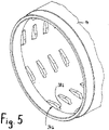
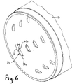
- figure 2 shows a three-dimensional representation of one end of the one-piece container tube 14 made of ceramic material in a state removed from the agitator mill 10. It is easy to see that on the inside 28 of the grinding container, a large number of cams 34 are arranged along a plurality of circumferential lines U spaced apart from one another in the axial direction X (a circumferential line U is shown as an example in 2 shown) of the inside of the grinding container are each arranged in a row one after the other.
- the distance between two axially adjacent rows of cams is a, the distance between two cams 34 following one another along a circumferential line in the circumferential direction is denoted by A.
- all cams 34 have the same distance A from one another in the circumferential direction
- the axial distance a between two rows of cams is the same for all rows of cams
- the cams 34 that follow one another in the axial direction are each aligned with one another.
- the cams of two axially adjacent rows of cams can be offset from one another and/or the distance A in the circumferential direction can vary, even within a single row of cams.
- the axial distance a does not have to be the same for all rows of cams, but can be selected differently, for example in order to increase or decrease a cam density in certain sections of the inside 28 of the grinding container.
- Each cam 34 is characterized by specific parameters, of which the greatest height h measured normal to the inside 28 of the grinding container has already been mentioned.
- the greatest height h of the cams 34 is at in 2 embodiment shown selected so that there is an overlapping arrangement with the stirring rods 36, ie it applies MS - H ⁇ h.
- the free end sections of the stirring rods 36 accordingly dip into the gaps existing between the axially spaced rows of cams.
- a clarification of this condition, albeit with a different cam shape, is given in figure 10 shown.
- Each cam 34 rests with its base or connecting surface F Zyl on the inside 28 of the grinding container.
- the connecting surface F Zyl of a cam 34 is shown hatched.
- the greatest width of this connection surface F Zyl is denoted by B, while the greatest length of the connection length F Zyl is denoted by L.
- the width of the connection surface F cyl has the value of the greatest width B over the entire length L of the connection surface F cyl , but this may be different in other embodiments.
- the greatest width B can only occur at one point along the length of a cam 34, or only in a specific area.
- the connecting surface F Zyl of a cam 34 is also a cylindrically curved surface and that the length L and the distance A can be given in radians.
- each cam 34 has a face-side inflow surface 38 which, in the case of the in figure 2 cam 34 shown is steeper than a ramp-like gently inclined outflow surface 40 arranged on the cam 34 opposite to the inflow surface 38.
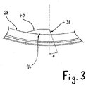
- the apparent angle of inclination ⁇ of the face-side inflow surface 38 can be in a range of ⁇ 45° ⁇ 85° with respect to a plane that is normal to the inside of the grinding container.
- An angle ⁇ > 0° corresponds to an inclination of the face-side inflow surface 38, as shown in figure 2 is shown and in which a arranged on the inside 28 of the grinding container, lower edge of the inflow surface 38 is first contacted by the inflowing medium.
- an angle ⁇ ⁇ 0° means that a radially upper edge of the front-side inflow surface 38 precedes the previously described lower edge, i.e. such an inclined front-side inflow surface 38 leads to the formation of a cam 34 that is undercut on the inflow side.
- cam 34 the ratio of the greatest height h of each cam 34 and the inside diameter d of the grinding container is ⁇ 0.05, i.e. H. h/d ⁇ 0.05. It also applies to all cams 34 that the ratio of the greatest height h of each cam 34 and the milling gap width MS is ⁇ 0.35, i.e. H. h/ms ⁇ 0.35.
- the distance A between two consecutive cams 34 in the circumferential direction is advantageously at least as large as the greatest length L of a cam 34 or its connecting surface F cyl .
- a plurality of cams 34 are arranged in a row along a plurality of circumferential lines spaced apart from one another in the axial direction, then an axial distance a between each two is advantageously axial adjacent rows of cams at least 1.1 times the greatest width B of a cam 34 or its connecting surface F cyl .
- the length of the cams 34 does not necessarily have to extend on a circumferential line, but can be arranged inclined at the angle ⁇ relative to a circumferential line of the inside of the grinding container 28, this angle ⁇ preferably being in a range of -22.5 ° ⁇ ⁇ ⁇ 22.5°.
- the one-piece container tube 14 is preferably made of silicon carbide or silicon carbide with free silicon, the cams 34 then advantageously being made of the same material.
- cams 34 are shown, which are attached to the inside 28 of the grinding container.
- figure 4 shows cam 34a similar to that in FIG figure 2 Cams 34 shown, but with the cams 34a the frontal inflow surface 38a is exactly normal to the grinding container inside 28 and the greatest height h is significantly lower, so that the end sections of the stirring rods 36 do not dip into the gaps existing between the rows of cams, ie it applies MS - H > h. This state is in figure 9 clarified.
- FIG. 12 shows cam 34b having a shape similar to cam 34.
- FIG figure 2 shows cams 34b, the face-side inflow surface 38b has a shovel-like curved shape.
- figure 6 shows cam 34c, the height h of which is constant over the entire length L (neglecting the height differences resulting from the curved connecting surface F Zyl ).
- figure 7 shows cam 34d with a similar figure 2 slightly inclined frontal inflow surface 38d, but in contrast to figure 2 runs tapered like a wedge.
- the rear outflow surface 40d is rounded and has an inclination that corresponds approximately to that of the front inflow surface 38d. Because of the greater height h, this is a cam arrangement that overlaps the stirring rods 36 .
- the cams 34d are all inclined at the same angle ⁇ with respect to a peripheral line U of the inside 28 of the grinding container.
- cam 34e shows the cam off with a figure 7 corresponding form, but in contrast to figure 7 are arranged in reverse, ie the rounded face of the cam is the inflow face 38e and the wedge-like pointed face of the cam is the outflow face 40e. In further difference to figure 7 all cams 34e are each arranged along a circumferential line and not at an angle to it.
- figure 9 shows by means of a cam 34a figure 4 and a stirring bar 36, a non-overlapping arrangement of cams and stirring bars, ie the stirring bars 36 do not dip into the gaps existing between the rows of cams due to the small height h of the cams.
- FIG figure 10 shows by means of a cam 34d figure 7 and a stirring rod 36 an overlapping arrangement of cams and stirring rods, ie the height h of the cams is so great that in the side projection view of FIG figure 10 the free end of the stirring rod 36 overlaps with the cam 34d, which means nothing other than that during operation of the agitator mill, the stirring rods 36 dip into the gaps existing between the axially spaced rows of cams.
Landscapes
- Engineering & Computer Science (AREA)
- Food Science & Technology (AREA)
- Crushing And Grinding (AREA)
Claims (10)
- Broyeur agitateur à billes (10) comprenant :- un récipient de broyage (12) dont le côté intérieur (28) est constitué d'un matériau céramique, le récipient de broyage (12) s'étendant le long d'un axe (X) et présentant un diamètre intérieur (d),- un rotor (20) disposé à l'intérieur du récipient de broyage (12) et apte à être entraîné en rotation autour de l'axe (X), avec une surface supérieure (30) tournée vers le côté intérieur du récipient de broyage (12), une fente de broyage (32) avec une largeur de fente de broyage (MS) étant formée entre la surface supérieure (30) du rotor (20) et le côté intérieur du récipient de broyage (12),- plusieurs ergots (34) fixés au côté intérieur (28) du récipient de broyage (12) et s'étendant radialement vers l'intérieur à partir du côté intérieur du récipient de broyage avec une hauteur (h), perpendiculairement au côté intérieur du récipient de broyage,caractérisé en ce que- le côté intérieur du récipient de broyage (12) est formé par un tuyau de récipient (14) monobloc constitué d'un matériau céramique, où les ergots (34) sont formés de manière intégrale avec le tuyau de récipient (14),- le rapport entre la hauteur (h) de chaque ergot (34) et le diamètre intérieur (d) du récipient de broyage (12) est ≤ 0,05, et- le rapport entre la hauteur (h) de chaque ergot (34) et la largeur de fente de broyage (MS) est ≤ 0,35.
- Broyeur agitateur à billes selon la revendication 1,
caractérisé en ce que le tuyau de récipient (14) et les ergots (34) sont constitués de carbure de silicium (SiC) ou de carbure de silicium avec du silicium libre (SiSiC). - Broyeur agitateur à billes selon la revendication 1 ou 2,
caractérisé en ce que chaque ergot (34) présente une surface de liaison (FZyl) avec le côté intérieur (28) du récipient de broyage, avec une largeur maximale (B), et le rapport entre la hauteur (h) de chaque ergot (34) et la largeur maximale (B) est supérieur à 0,2. - Broyeur agitateur à billes selon l'une des revendications 1 à 3,
caractérisé en ce que chaque ergot (34) présente une surface de liaison (FZyl) avec le côté intérieur (28) du récipient de broyage, avec une longueur maximale (L), et le rapport entre la hauteur (h) de chaque ergot (34) et la longueur maximale (L) est inférieur à 1. - Broyeur agitateur à billes selon l'une des revendications précédentes,
caractérisé en ce que chaque ergot (34) présente une surface de liaison (FZyl) avec le côté intérieur (28) du récipient de broyage, avec une longueur maximale (L) et une largeur maximale (B), où le rapport entre la largeur maximale (B) et la longueur maximale (L) est inférieur à 1. - Broyeur agitateur à billes selon l'une des revendications précédentes,
caractérisé en ce que chaque ergot (34) présente une surface de liaison (FZyl) avec le côté intérieur (28) du récipient de broyage et une surface d'afflux frontale (38), où un rapport entre une projection (Fu) de la surface d'afflux frontale (38) sur un plan s'étendant perpendiculairement au côté intérieur du récipient de broyage et la surface de liaison (FZyl) est inférieur à 1. - Broyeur agitateur à billes selon la revendication 6,
caractérisé en ce qu'un angle d'inclinaison (α) de la surface d'afflux frontale (38) par rapport au plan s'étendant perpendiculairement au côté intérieur du récipient de broyage est compris dans une plage de -45° < α < 85°, où avec un angle α > 0°, un bord inférieur de la surface d'afflux frontale (38) disposé sur le côté intérieur du récipient de broyage est touché en premier par un fluide affluent, et avec un angle α < 0° un bord radialement supérieur de la surface d'afflux frontale (38) précède ledit bord inférieur. - Broyeur agitateur à billes selon l'une des revendications 4 à 7,
caractérisé en ce que plusieurs ergots (34) sont disposés successivement dans une rangée le long d'une ligne périphérique, dans le sens périphérique du côté intérieur du récipient de broyage, et un écart (A) entre des ergots successifs (34) dans le sens périphérique est ≥ la longueur maximale (L) d'un ergot (34). - Broyeur agitateur à billes selon l'une des revendications 3 à 8,
caractérisé en ce que plusieurs ergots (34) sont disposés successivement respectivement dans une rangée le long de plusieurs lignes périphériques espacées les unes des autres dans la direction axiale (X), et en ce qu'un écart axial (a) entre deux rangées d'ergots respectives adjacentes axialement est supérieur ou égal à 1,1 fois la largeur maximale (B) d'un ergot (34). - Broyeur agitateur à billes selon la revendication 8 ou 9,
caractérisé en ce que certains ou la totalité des ergots (34) vus en plan sont disposés sous un angle (β) par rapport à la ligne périphérique correspondante, où l'angle (β) est de préférence compris dans une plage de -22,5° ≤ β ≤ 22,5°.
Priority Applications (5)
| Application Number | Priority Date | Filing Date | Title |
|---|---|---|---|
| ES17000174T ES2738664T5 (es) | 2017-02-03 | 2017-02-03 | Molino de bolas con mecanismo agitador con revestimiento cerámico |
| EP17000174.7A EP3357580B2 (fr) | 2017-02-03 | 2017-02-03 | Broyeur agitateur ayant un revêtement en céramique |
| PL17000174.7T PL3357580T5 (pl) | 2017-02-03 | 2017-02-03 | Mieszadłowy młyn perełkowy z wykładziną ceramiczną |
| BR102018001608-3A BR102018001608B1 (pt) | 2017-02-03 | 2018-01-25 | Moinho de esferas agitador com revestimento em cerâmica |
| US15/887,548 US10870116B2 (en) | 2017-02-03 | 2018-02-02 | Agitator ball mill with ceramic lining |
Applications Claiming Priority (1)
| Application Number | Priority Date | Filing Date | Title |
|---|---|---|---|
| EP17000174.7A EP3357580B2 (fr) | 2017-02-03 | 2017-02-03 | Broyeur agitateur ayant un revêtement en céramique |
Publications (3)
| Publication Number | Publication Date |
|---|---|
| EP3357580A1 EP3357580A1 (fr) | 2018-08-08 |
| EP3357580B1 EP3357580B1 (fr) | 2019-05-15 |
| EP3357580B2 true EP3357580B2 (fr) | 2022-11-02 |
Family
ID=57995003
Family Applications (1)
| Application Number | Title | Priority Date | Filing Date |
|---|---|---|---|
| EP17000174.7A Active EP3357580B2 (fr) | 2017-02-03 | 2017-02-03 | Broyeur agitateur ayant un revêtement en céramique |
Country Status (4)
| Country | Link |
|---|---|
| US (1) | US10870116B2 (fr) |
| EP (1) | EP3357580B2 (fr) |
| ES (1) | ES2738664T5 (fr) |
| PL (1) | PL3357580T5 (fr) |
Families Citing this family (1)
| Publication number | Priority date | Publication date | Assignee | Title |
|---|---|---|---|---|
| CN119237099B (zh) * | 2024-11-05 | 2025-09-30 | 东莞市琅菱机械有限公司 | 一种卧式砂磨机的研磨结构 |
Citations (3)
| Publication number | Priority date | Publication date | Assignee | Title |
|---|---|---|---|---|
| DE2629251A1 (de) † | 1976-06-30 | 1978-01-12 | Draiswerke Gmbh | Ruehrwerksmuehle |
| DE4401384A1 (de) † | 1993-02-25 | 1994-09-01 | Buehler Ag | Rührwerksmühle |
| US9339778B2 (en) † | 2010-03-01 | 2016-05-17 | Kureha Corporation | Column-type solid-liquid countercurrent contact apparatus, solid particle washing apparatus, and method |
Family Cites Families (6)
| Publication number | Priority date | Publication date | Assignee | Title |
|---|---|---|---|---|
| JPH06102164B2 (ja) | 1986-10-09 | 1994-12-14 | 日本セメント株式会社 | 粉砕機 |
| DE3723558A1 (de) * | 1987-07-16 | 1989-01-26 | Netzsch Erich Holding | Muehle, insbesondere ruehrwerksmuehle |
| CH682465A5 (de) | 1988-06-09 | 1993-09-30 | Buehler Ag | Rührwerksmühle. |
| US7571871B2 (en) * | 2005-11-04 | 2009-08-11 | Rutgers, The State University Of New Jersey | Uniform shear application system and methods relating thereto |
| JP2014155913A (ja) | 2013-02-18 | 2014-08-28 | Ricoh Co Ltd | メディア式分散機及びトナー製造方法 |
| MX2019008669A (es) * | 2017-01-26 | 2019-09-13 | Outotec Finland Oy | Mejoras en molinos de lecho agitado. |
-
2017
- 2017-02-03 PL PL17000174.7T patent/PL3357580T5/pl unknown
- 2017-02-03 ES ES17000174T patent/ES2738664T5/es active Active
- 2017-02-03 EP EP17000174.7A patent/EP3357580B2/fr active Active
-
2018
- 2018-02-02 US US15/887,548 patent/US10870116B2/en active Active
Patent Citations (3)
| Publication number | Priority date | Publication date | Assignee | Title |
|---|---|---|---|---|
| DE2629251A1 (de) † | 1976-06-30 | 1978-01-12 | Draiswerke Gmbh | Ruehrwerksmuehle |
| DE4401384A1 (de) † | 1993-02-25 | 1994-09-01 | Buehler Ag | Rührwerksmühle |
| US9339778B2 (en) † | 2010-03-01 | 2016-05-17 | Kureha Corporation | Column-type solid-liquid countercurrent contact apparatus, solid particle washing apparatus, and method |
Non-Patent Citations (6)
| Title |
|---|
| Auszuge aus dem Ersatzteilkatalog zur Ruhrwerksmühle Micro MediaX3 † |
| Medienmitteilung der Bühler AG vom 11.04.2007 † |
| Micro Media - Ringraummühle fur die Nanotechnologie, Buhler AG, Dezember 2011 † |
| Micro Media Quality meets efficiency, Bühler AG, 25.01.2017 † |
| Präsentation von Dr. Stehr bei der firma IOCL † |
| Schreiben an die Bühler AG mit einem Belegexemplar der Fachzeitschrift Chemie Technik, November 2016 † |
Also Published As
| Publication number | Publication date |
|---|---|
| PL3357580T3 (pl) | 2019-11-29 |
| US10870116B2 (en) | 2020-12-22 |
| EP3357580A1 (fr) | 2018-08-08 |
| ES2738664T5 (es) | 2023-02-13 |
| US20180221888A1 (en) | 2018-08-09 |
| ES2738664T3 (es) | 2020-01-24 |
| PL3357580T5 (pl) | 2023-03-13 |
| BR102018001608A2 (pt) | 2018-12-04 |
| EP3357580B1 (fr) | 2019-05-15 |
Similar Documents
| Publication | Publication Date | Title |
|---|---|---|
| EP1899070B1 (fr) | Broyeur a cylindres pour broyer des blocs de ciment brulants | |
| EP0737096B1 (fr) | Utilisation d'un melangeur pour concher | |
| DE102018122408B4 (de) | Rührwerkskugelmühle, Verschleißschutzhülse für eine Rührwerkskugelmühle und Verfahren zum Herstellen einer Verschleißschutzhülse für eine Rührwerkskugelmühle | |
| DE2548812A1 (de) | Mahlvorrichtung, wie pfeffermuehle o.dgl. | |
| EP3283204B1 (fr) | Dispositif et procédé de mélange, en particulier de dispersion | |
| CH688849A5 (de) | Ruehrwerksmuehle. | |
| DE102018122395B4 (de) | Rührwelle für eine Rührwerkskugelmühle, Rührwerkskugelmühle und Verfahren zum Herstellen einer Rührwelle für eine Rührwerkskugelmühle | |
| EP3311922A1 (fr) | Broyeur à billes à agitateur | |
| DE202013104078U1 (de) | Brechwalze | |
| CH709952B1 (de) | Medien-Rührwerk-Pulverisiergerät. | |
| DE102017118051B4 (de) | Rührwerk für eine Rührwerkskugelmühle | |
| WO2019170661A1 (fr) | Broyeur à agitateur avec ensemble de tiges asynchrone | |
| EP3357580B2 (fr) | Broyeur agitateur ayant un revêtement en céramique | |
| EP0504836A1 (fr) | Broyeur agitateur | |
| EP3290120A1 (fr) | Rotor de broyeur doté d'un porte-lames fixé de manière amovible | |
| DE1187112B (de) | Wirbelmuehle | |
| DE4440769C2 (de) | Vorrichtung zum Zerkleinern und Agglomerieren von Kunststoffabfällen | |
| DE2348763C3 (de) | Zusammengesetzte Auskleidung in einer Mühle | |
| DE69007435T2 (de) | Vorrichtung zum Zerkleinern und Dispergieren. | |
| EP0584151B1 (fr) | Outil melangeur | |
| DE1607446B1 (de) | Ruehrwerksmuehle | |
| DE1477976A1 (de) | Teilchenstrahlvorrichtung | |
| EP2785462A1 (fr) | Dispositif et procédé de traitement de matériaux | |
| DE3520483C2 (de) | Wand mit Schlitzen | |
| EP0034139B1 (fr) | Marteau coulé pour une machine à forger |
Legal Events
| Date | Code | Title | Description |
|---|---|---|---|
| PUAI | Public reference made under article 153(3) epc to a published international application that has entered the european phase |
Free format text: ORIGINAL CODE: 0009012 |
|
| STAA | Information on the status of an ep patent application or granted ep patent |
Free format text: STATUS: REQUEST FOR EXAMINATION WAS MADE |
|
| 17P | Request for examination filed |
Effective date: 20170203 |
|
| AK | Designated contracting states |
Kind code of ref document: A1 Designated state(s): AL AT BE BG CH CY CZ DE DK EE ES FI FR GB GR HR HU IE IS IT LI LT LU LV MC MK MT NL NO PL PT RO RS SE SI SK SM TR |
|
| AX | Request for extension of the european patent |
Extension state: BA ME |
|
| GRAP | Despatch of communication of intention to grant a patent |
Free format text: ORIGINAL CODE: EPIDOSNIGR1 |
|
| STAA | Information on the status of an ep patent application or granted ep patent |
Free format text: STATUS: GRANT OF PATENT IS INTENDED |
|
| INTG | Intention to grant announced |
Effective date: 20181213 |
|
| GRAS | Grant fee paid |
Free format text: ORIGINAL CODE: EPIDOSNIGR3 |
|
| GRAA | (expected) grant |
Free format text: ORIGINAL CODE: 0009210 |
|
| STAA | Information on the status of an ep patent application or granted ep patent |
Free format text: STATUS: THE PATENT HAS BEEN GRANTED |
|
| AK | Designated contracting states |
Kind code of ref document: B1 Designated state(s): AL AT BE BG CH CY CZ DE DK EE ES FI FR GB GR HR HU IE IS IT LI LT LU LV MC MK MT NL NO PL PT RO RS SE SI SK SM TR |
|
| REG | Reference to a national code |
Ref country code: CH Ref legal event code: EP |
|
| REG | Reference to a national code |
Ref country code: IE Ref legal event code: FG4D Free format text: LANGUAGE OF EP DOCUMENT: GERMAN |
|
| REG | Reference to a national code |
Ref country code: DE Ref legal event code: R096 Ref document number: 502017001270 Country of ref document: DE |
|
| REG | Reference to a national code |
Ref country code: NL Ref legal event code: FP |
|
| REG | Reference to a national code |
Ref country code: LT Ref legal event code: MG4D |
|
| PG25 | Lapsed in a contracting state [announced via postgrant information from national office to epo] |
Ref country code: HR Free format text: LAPSE BECAUSE OF FAILURE TO SUBMIT A TRANSLATION OF THE DESCRIPTION OR TO PAY THE FEE WITHIN THE PRESCRIBED TIME-LIMIT Effective date: 20190515 Ref country code: LT Free format text: LAPSE BECAUSE OF FAILURE TO SUBMIT A TRANSLATION OF THE DESCRIPTION OR TO PAY THE FEE WITHIN THE PRESCRIBED TIME-LIMIT Effective date: 20190515 Ref country code: NO Free format text: LAPSE BECAUSE OF FAILURE TO SUBMIT A TRANSLATION OF THE DESCRIPTION OR TO PAY THE FEE WITHIN THE PRESCRIBED TIME-LIMIT Effective date: 20190815 Ref country code: SE Free format text: LAPSE BECAUSE OF FAILURE TO SUBMIT A TRANSLATION OF THE DESCRIPTION OR TO PAY THE FEE WITHIN THE PRESCRIBED TIME-LIMIT Effective date: 20190515 Ref country code: PT Free format text: LAPSE BECAUSE OF FAILURE TO SUBMIT A TRANSLATION OF THE DESCRIPTION OR TO PAY THE FEE WITHIN THE PRESCRIBED TIME-LIMIT Effective date: 20190915 Ref country code: AL Free format text: LAPSE BECAUSE OF FAILURE TO SUBMIT A TRANSLATION OF THE DESCRIPTION OR TO PAY THE FEE WITHIN THE PRESCRIBED TIME-LIMIT Effective date: 20190515 Ref country code: FI Free format text: LAPSE BECAUSE OF FAILURE TO SUBMIT A TRANSLATION OF THE DESCRIPTION OR TO PAY THE FEE WITHIN THE PRESCRIBED TIME-LIMIT Effective date: 20190515 |
|
| PG25 | Lapsed in a contracting state [announced via postgrant information from national office to epo] |
Ref country code: BG Free format text: LAPSE BECAUSE OF FAILURE TO SUBMIT A TRANSLATION OF THE DESCRIPTION OR TO PAY THE FEE WITHIN THE PRESCRIBED TIME-LIMIT Effective date: 20190815 Ref country code: GR Free format text: LAPSE BECAUSE OF FAILURE TO SUBMIT A TRANSLATION OF THE DESCRIPTION OR TO PAY THE FEE WITHIN THE PRESCRIBED TIME-LIMIT Effective date: 20190816 Ref country code: RS Free format text: LAPSE BECAUSE OF FAILURE TO SUBMIT A TRANSLATION OF THE DESCRIPTION OR TO PAY THE FEE WITHIN THE PRESCRIBED TIME-LIMIT Effective date: 20190515 Ref country code: LV Free format text: LAPSE BECAUSE OF FAILURE TO SUBMIT A TRANSLATION OF THE DESCRIPTION OR TO PAY THE FEE WITHIN THE PRESCRIBED TIME-LIMIT Effective date: 20190515 |
|
| REG | Reference to a national code |
Ref country code: ES Ref legal event code: FG2A Ref document number: 2738664 Country of ref document: ES Kind code of ref document: T3 Effective date: 20200124 |
|
| PG25 | Lapsed in a contracting state [announced via postgrant information from national office to epo] |
Ref country code: EE Free format text: LAPSE BECAUSE OF FAILURE TO SUBMIT A TRANSLATION OF THE DESCRIPTION OR TO PAY THE FEE WITHIN THE PRESCRIBED TIME-LIMIT Effective date: 20190515 Ref country code: DK Free format text: LAPSE BECAUSE OF FAILURE TO SUBMIT A TRANSLATION OF THE DESCRIPTION OR TO PAY THE FEE WITHIN THE PRESCRIBED TIME-LIMIT Effective date: 20190515 Ref country code: SK Free format text: LAPSE BECAUSE OF FAILURE TO SUBMIT A TRANSLATION OF THE DESCRIPTION OR TO PAY THE FEE WITHIN THE PRESCRIBED TIME-LIMIT Effective date: 20190515 Ref country code: CZ Free format text: LAPSE BECAUSE OF FAILURE TO SUBMIT A TRANSLATION OF THE DESCRIPTION OR TO PAY THE FEE WITHIN THE PRESCRIBED TIME-LIMIT Effective date: 20190515 |
|
| REG | Reference to a national code |
Ref country code: DE Ref legal event code: R026 Ref document number: 502017001270 Country of ref document: DE |
|
| PLBI | Opposition filed |
Free format text: ORIGINAL CODE: 0009260 |
|
| PG25 | Lapsed in a contracting state [announced via postgrant information from national office to epo] |
Ref country code: SM Free format text: LAPSE BECAUSE OF FAILURE TO SUBMIT A TRANSLATION OF THE DESCRIPTION OR TO PAY THE FEE WITHIN THE PRESCRIBED TIME-LIMIT Effective date: 20190515 |
|
| PLAX | Notice of opposition and request to file observation + time limit sent |
Free format text: ORIGINAL CODE: EPIDOSNOBS2 |
|
| 26 | Opposition filed |
Opponent name: BUEHLER AG Effective date: 20200214 |
|
| PG25 | Lapsed in a contracting state [announced via postgrant information from national office to epo] |
Ref country code: TR Free format text: LAPSE BECAUSE OF FAILURE TO SUBMIT A TRANSLATION OF THE DESCRIPTION OR TO PAY THE FEE WITHIN THE PRESCRIBED TIME-LIMIT Effective date: 20190515 |
|
| PLBB | Reply of patent proprietor to notice(s) of opposition received |
Free format text: ORIGINAL CODE: EPIDOSNOBS3 |
|
| REG | Reference to a national code |
Ref country code: BE Ref legal event code: MM Effective date: 20200229 |
|
| PG25 | Lapsed in a contracting state [announced via postgrant information from national office to epo] |
Ref country code: MC Free format text: LAPSE BECAUSE OF FAILURE TO SUBMIT A TRANSLATION OF THE DESCRIPTION OR TO PAY THE FEE WITHIN THE PRESCRIBED TIME-LIMIT Effective date: 20190515 Ref country code: LU Free format text: LAPSE BECAUSE OF NON-PAYMENT OF DUE FEES Effective date: 20200203 |
|
| PG25 | Lapsed in a contracting state [announced via postgrant information from national office to epo] |
Ref country code: IE Free format text: LAPSE BECAUSE OF NON-PAYMENT OF DUE FEES Effective date: 20200203 |
|
| PG25 | Lapsed in a contracting state [announced via postgrant information from national office to epo] |
Ref country code: BE Free format text: LAPSE BECAUSE OF NON-PAYMENT OF DUE FEES Effective date: 20200229 |
|
| PG25 | Lapsed in a contracting state [announced via postgrant information from national office to epo] |
Ref country code: MT Free format text: LAPSE BECAUSE OF FAILURE TO SUBMIT A TRANSLATION OF THE DESCRIPTION OR TO PAY THE FEE WITHIN THE PRESCRIBED TIME-LIMIT Effective date: 20190515 Ref country code: CY Free format text: LAPSE BECAUSE OF FAILURE TO SUBMIT A TRANSLATION OF THE DESCRIPTION OR TO PAY THE FEE WITHIN THE PRESCRIBED TIME-LIMIT Effective date: 20190515 |
|
| PG25 | Lapsed in a contracting state [announced via postgrant information from national office to epo] |
Ref country code: RO Free format text: LAPSE BECAUSE OF FAILURE TO SUBMIT A TRANSLATION OF THE DESCRIPTION OR TO PAY THE FEE WITHIN THE PRESCRIBED TIME-LIMIT Effective date: 20190515 Ref country code: MK Free format text: LAPSE BECAUSE OF FAILURE TO SUBMIT A TRANSLATION OF THE DESCRIPTION OR TO PAY THE FEE WITHIN THE PRESCRIBED TIME-LIMIT Effective date: 20190515 Ref country code: IS Free format text: LAPSE BECAUSE OF FAILURE TO SUBMIT A TRANSLATION OF THE DESCRIPTION OR TO PAY THE FEE WITHIN THE PRESCRIBED TIME-LIMIT Effective date: 20190915 |
|
| PUAH | Patent maintained in amended form |
Free format text: ORIGINAL CODE: 0009272 |
|
| STAA | Information on the status of an ep patent application or granted ep patent |
Free format text: STATUS: PATENT MAINTAINED AS AMENDED |
|
| 27A | Patent maintained in amended form |
Effective date: 20221102 |
|
| AK | Designated contracting states |
Kind code of ref document: B2 Designated state(s): AL AT BE BG CH CY CZ DE DK EE ES FI FR GB GR HR HU IE IS IT LI LT LU LV MC MK MT NL NO PL PT RO RS SE SI SK SM TR |
|
| REG | Reference to a national code |
Ref country code: DE Ref legal event code: R102 Ref document number: 502017001270 Country of ref document: DE |
|
| REG | Reference to a national code |
Ref country code: NL Ref legal event code: FP |
|
| REG | Reference to a national code |
Ref country code: ES Ref legal event code: DC2A Ref document number: 2738664 Country of ref document: ES Kind code of ref document: T5 Effective date: 20230213 |
|
| REG | Reference to a national code |
Ref country code: AT Ref legal event code: MM01 Ref document number: 1132817 Country of ref document: AT Kind code of ref document: T Effective date: 20220203 |
|
| PG25 | Lapsed in a contracting state [announced via postgrant information from national office to epo] |
Ref country code: AT Free format text: LAPSE BECAUSE OF NON-PAYMENT OF DUE FEES Effective date: 20220203 |
|
| P01 | Opt-out of the competence of the unified patent court (upc) registered |
Effective date: 20230524 |
|
| PG25 | Lapsed in a contracting state [announced via postgrant information from national office to epo] |
Ref country code: SI Free format text: LAPSE BECAUSE OF FAILURE TO SUBMIT A TRANSLATION OF THE DESCRIPTION OR TO PAY THE FEE WITHIN THE PRESCRIBED TIME-LIMIT Effective date: 20190515 |
|
| REG | Reference to a national code |
Ref country code: CH Ref legal event code: U11 Free format text: ST27 STATUS EVENT CODE: U-0-0-U10-U11 (AS PROVIDED BY THE NATIONAL OFFICE) Effective date: 20260301 |
|
| PGFP | Annual fee paid to national office [announced via postgrant information from national office to epo] |
Ref country code: NL Payment date: 20260228 Year of fee payment: 10 |
|
| PGFP | Annual fee paid to national office [announced via postgrant information from national office to epo] |
Ref country code: GB Payment date: 20260226 Year of fee payment: 10 |
|
| PGFP | Annual fee paid to national office [announced via postgrant information from national office to epo] |
Ref country code: ES Payment date: 20260302 Year of fee payment: 10 |
|
| PGFP | Annual fee paid to national office [announced via postgrant information from national office to epo] |
Ref country code: DE Payment date: 20260303 Year of fee payment: 10 |
|
| PGFP | Annual fee paid to national office [announced via postgrant information from national office to epo] |
Ref country code: IT Payment date: 20260227 Year of fee payment: 10 |
|
| PGFP | Annual fee paid to national office [announced via postgrant information from national office to epo] |
Ref country code: FR Payment date: 20260225 Year of fee payment: 10 |
|
| PGFP | Annual fee paid to national office [announced via postgrant information from national office to epo] |
Ref country code: CH Payment date: 20260301 Year of fee payment: 10 |
|
| PGFP | Annual fee paid to national office [announced via postgrant information from national office to epo] |
Ref country code: PL Payment date: 20260121 Year of fee payment: 10 |