EP3357617B1 - Dispositif d'usinage de profilé, ligne d'usinage de profilé et procédé - Google Patents
Dispositif d'usinage de profilé, ligne d'usinage de profilé et procédé Download PDFInfo
- Publication number
- EP3357617B1 EP3357617B1 EP17154122.0A EP17154122A EP3357617B1 EP 3357617 B1 EP3357617 B1 EP 3357617B1 EP 17154122 A EP17154122 A EP 17154122A EP 3357617 B1 EP3357617 B1 EP 3357617B1
- Authority
- EP
- European Patent Office
- Prior art keywords
- machining
- workpiece
- rotation
- unit
- processing
- Prior art date
- Legal status (The legal status is an assumption and is not a legal conclusion. Google has not performed a legal analysis and makes no representation as to the accuracy of the status listed.)
- Active
Links
Images





Classifications
-
- B—PERFORMING OPERATIONS; TRANSPORTING
- B23—MACHINE TOOLS; METAL-WORKING NOT OTHERWISE PROVIDED FOR
- B23C—MILLING
- B23C3/00—Milling particular work; Special milling operations; Machines therefor
- B23C3/12—Trimming or finishing edges, e.g. deburring welded corners
- B23C3/128—Trimming or finishing edges of doors and windows
-
- B—PERFORMING OPERATIONS; TRANSPORTING
- B27—WORKING OR PRESERVING WOOD OR SIMILAR MATERIAL; NAILING OR STAPLING MACHINES IN GENERAL
- B27C—PLANING, DRILLING, MILLING, TURNING OR UNIVERSAL MACHINES FOR WOOD OR SIMILAR MATERIAL
- B27C3/00—Drilling machines or drilling devices; Equipment therefor
- B27C3/04—Stationary drilling machines with a plurality of working spindles
-
- B—PERFORMING OPERATIONS; TRANSPORTING
- B27—WORKING OR PRESERVING WOOD OR SIMILAR MATERIAL; NAILING OR STAPLING MACHINES IN GENERAL
- B27C—PLANING, DRILLING, MILLING, TURNING OR UNIVERSAL MACHINES FOR WOOD OR SIMILAR MATERIAL
- B27C5/00—Machines designed for producing special profiles or shaped work, e.g. by rotary cutters; Equipment therefor
-
- B—PERFORMING OPERATIONS; TRANSPORTING
- B27—WORKING OR PRESERVING WOOD OR SIMILAR MATERIAL; NAILING OR STAPLING MACHINES IN GENERAL
- B27C—PLANING, DRILLING, MILLING, TURNING OR UNIVERSAL MACHINES FOR WOOD OR SIMILAR MATERIAL
- B27C9/00—Multi-purpose machines; Universal machines; Equipment therefor
- B27C9/04—Multi-purpose machines; Universal machines; Equipment therefor with a plurality of working spindles
-
- B—PERFORMING OPERATIONS; TRANSPORTING
- B27—WORKING OR PRESERVING WOOD OR SIMILAR MATERIAL; NAILING OR STAPLING MACHINES IN GENERAL
- B27M—WORKING OF WOOD NOT PROVIDED FOR IN SUBCLASSES B27B - B27L; MANUFACTURE OF SPECIFIC WOODEN ARTICLES
- B27M1/00—Working of wood not provided for in subclasses B27B - B27L, e.g. by stretching
- B27M1/08—Working of wood not provided for in subclasses B27B - B27L, e.g. by stretching by multi-step processes
-
- B—PERFORMING OPERATIONS; TRANSPORTING
- B27—WORKING OR PRESERVING WOOD OR SIMILAR MATERIAL; NAILING OR STAPLING MACHINES IN GENERAL
- B27M—WORKING OF WOOD NOT PROVIDED FOR IN SUBCLASSES B27B - B27L; MANUFACTURE OF SPECIFIC WOODEN ARTICLES
- B27M3/00—Manufacture or reconditioning of specific semi-finished or finished articles
- B27M3/0013—Manufacture or reconditioning of specific semi-finished or finished articles of composite or compound articles
- B27M3/002—Manufacture or reconditioning of specific semi-finished or finished articles of composite or compound articles characterised by oblong elements connected at their ends
-
- B—PERFORMING OPERATIONS; TRANSPORTING
- B23—MACHINE TOOLS; METAL-WORKING NOT OTHERWISE PROVIDED FOR
- B23B—TURNING; BORING
- B23B2260/00—Details of constructional elements
- B23B2260/116—Rollers or rolls
-
- B—PERFORMING OPERATIONS; TRANSPORTING
- B23—MACHINE TOOLS; METAL-WORKING NOT OTHERWISE PROVIDED FOR
- B23P—METAL-WORKING NOT OTHERWISE PROVIDED FOR; COMBINED OPERATIONS; UNIVERSAL MACHINE TOOLS
- B23P23/00—Machines or arrangements of machines for performing specified combinations of different metal-working operations not covered by a single other subclass
- B23P23/02—Machine tools for performing different machining operations
-
- B—PERFORMING OPERATIONS; TRANSPORTING
- B23—MACHINE TOOLS; METAL-WORKING NOT OTHERWISE PROVIDED FOR
- B23Q—DETAILS, COMPONENTS, OR ACCESSORIES FOR MACHINE TOOLS, e.g. ARRANGEMENTS FOR COPYING OR CONTROLLING; MACHINE TOOLS IN GENERAL CHARACTERISED BY THE CONSTRUCTION OF PARTICULAR DETAILS OR COMPONENTS; COMBINATIONS OR ASSOCIATIONS OF METAL-WORKING MACHINES, NOT DIRECTED TO A PARTICULAR RESULT
- B23Q1/00—Members which are comprised in the general build-up of a form of machine, particularly relatively large fixed members
- B23Q1/25—Movable or adjustable work or tool supports
- B23Q1/44—Movable or adjustable work or tool supports using particular mechanisms
- B23Q1/48—Movable or adjustable work or tool supports using particular mechanisms with sliding pairs and rotating pairs
- B23Q1/4852—Movable or adjustable work or tool supports using particular mechanisms with sliding pairs and rotating pairs a single sliding pair followed perpendicularly by a single rotating pair
Definitions
- the present invention relates to a device for the machining of elongated workpieces, in the form of window or door frames or casements or blind frames composed of profile rods according to the preamble of claim 1, a profile machining line according to the preamble of claim 11 and a method for machining a workpiece mentioned above according to the preamble of claim 12.
- a device and profile processing line and such a method are from EP 2 366 480 A1 famous.
- Such devices can be provided within the scope of the invention, especially for making bores and/or millings and/or fasteners in a workpiece, for example for producing drainage slots, ventilation slots, ventilation slots, lock cases and olive bores, screwed hinges, screwed transoms, window and door frames.
- the workpiece in the form of such a frame can consist of profile bars, in particular of a thermoplastic material such as PVC.
- the ends of the profile bars are usually mitred in their connection area. In a joining machine, these are then heated for welding in their connection area until they are plastically deformable. Then the profile pieces are pressed against each other and thus a material bond is established between them. After the profile pieces have been pressed together in the connection area, the material-to-material weld created must cool down before the frame joined in this way can be subjected to greater mechanical loads.
- the pressing together during the joining process usually creates a weld bead from the displaced plastic in the area of the corner joints of the frame, which after the must be removed with the help of a post-processing machine, for example a corner cleaning machine.
- a post-processing machine for example a corner cleaning machine.
- machining can already take place during the cooling phase.
- the rectangular frames made of four profile bars in an upstream welding device are conveyed by a conveyor in a transport direction into the processing device and are fixed there for subsequent processing by gripping means.
- Two processing heads moving laterally on the frame process the two profile bars, which are aligned along the direction of transport.
- the partially machined frame is rotated by 90 degrees by means of a rotation device, so that it can also be machined on the two still unmachined profile bars in a second, downstream machining device.
- a disadvantage of such a device is that the profiled rods lying transversely to the direction of transport cannot be processed by the processing heads.
- additional processing heads that can be moved transversely to the transport direction can be provided, which, however, increase the complexity and the costs of such a processing device.
- an automatic corner cleaning machine with a processing unit which has a tool that can be freely pivoted or rotated about a vertical axis.
- the tool has contact flanks and is aligned with the frame by applying the contact flanks to the corner of the frame and locked in this position, so that the welding bead can be removed particularly precisely.
- the tool is mechanically aligned with the frame to be machined.
- a window processing system for use in the manufacture of window frames.
- the system includes a stationary mounted industrial robot with an articulated arm having a plurality of links that allow rotary motion about multiple axes.
- the system also includes a rotatable tool holder at the end of the articulating arm for a variety of tools for performing cleaning operations on a window frame.
- the window frame to be machined is arranged on a rotatable workpiece holder, by means of which the machining point of the window frame to be machined faces the robot arm.
- the invention is based on the object of specifying an improved device and an improved method of the type mentioned at the outset, with which a workpiece can be machined much more efficiently and flexibly.
- the object is achieved by a device according to claim 1, with a profile processing section according to claim 11 and with a method according to claim 12.
- a device namely a profiling machine for machining elongate workpieces.
- the workpieces are window or door frames or sashes or blind frames composed of profile rods.
- the workpiece to be machined can be arranged on a workpiece support.
- the workpiece and a processing head of the device are relative to one another in a direction of travel along the workpiece support movable, wherein a processing unit with at least one processing tool held thereon for processing the workpiece is arranged on the processing head.
- the processing unit is designed to be movable in a translatory manner in the positioning plane along at least one axis of rotation. Because the axis of rotation about which the processing unit can be rotated or pivoted and the positioning direction in which the processing unit can be moved translationally coincide or are parallel to one another, a simplified sequence of movements and thus simplified programming of the device becomes possible.
- the machining head and the workpiece can be moved relative to one another during the machining of the workpiece.
- more accurate and efficient machining of the workpiece and continuous machining operations are possible, so that, for example, longitudinal slots can be milled in the direction of travel in a continuous movement, which extend over a considerable part of the length of the workpiece.
- At least one device for fixing the workpiece in at least one spatial direction is arranged on the machining head.
- an accompanying tension roller device is provided for supporting the workpiece during workpiece processing, so that the invention can be used even more flexibly for faster processing of the entire workpiece.
- the processing unit can be moved in a positioning plane running transversely or perpendicularly to the direction of travel and can be rotated and/or pivoted in relation to the processing head about at least one axis of rotation running transversely or perpendicularly to the direction of travel by means of a drive.
- a positioning plane running transversely or perpendicularly to the direction of travel and can be rotated and/or pivoted in relation to the processing head about at least one axis of rotation running transversely or perpendicularly to the direction of travel by means of a drive.
- Such a configuration of the device makes it possible, in addition to the sections aligned in the direction of travel, also transversely or perpendicularly to the To process running sections of a frame or a workpiece by the same processing head. This is particularly advantageous in corner areas, where it is possible to mill drainage slots on a cross profile.
- sections of the workpiece that run lengthwise as well as transversely or perpendicularly to the direction of travel can be machined.
- this makes it possible to machine a workpiece on the side facing the machining head. For example, both the inside and the outside of a profile frame can be processed in this way. This can even make it possible to process a profiled bar that is opposite the processing head, so that all profiled bars of a frame can be processed by the same processing unit.
- the processing unit is designed to be movable in a translatory manner in the positioning plane along both axes of rotation. This enables an even further simplified movement sequence and thus simplified programming of the device.
- At least one position-controlled actuator in particular a servo drive, is provided for rotating the processing unit about the at least one axis of rotation and/or for displacing the processing unit along at least one of the axes of rotation.
- This enables the machining unit to be positioned particularly precisely.
- it can thereby be made possible to move the processing unit during the processing of the workpiece, see above that more complex machining operations can also be carried out, for example more complicated slot shapes can be milled.
- the at least one axis of rotation is aligned approximately parallel to a workpiece support plane of the workpiece support.
- the degrees of freedom in which the processing unit can be rotated or pivoted are aligned with a coordinate system that already exists for the device, resulting in a simplified movement sequence. This simplifies the programming as well as the assembly and setup of the device.
- the at least one axis of rotation is aligned approximately perpendicular to a workpiece support plane of the workpiece support.
- the processing unit is moved in a manner that is aligned with the coordinate system defined for the device in any case, so that the sequence of movements of the device is simplified and its programming is less complex.
- the machining unit can be aligned at a machining angle ⁇ of about 10° to about 70° and/or, preferably 0° to about 90°, rising from a workpiece support plane of the workpiece support, in particular at any angle between 0° to 360° adjustable. In this way, it is possible to produce drainage slots with different orientations. With an adjustability of 0° to 90° degrees, the processing of the side surfaces of a workpiece running perpendicular to the workpiece support plane is also better possible. For example, it may be possible to drill holes for a scissor stay hinge on the outside of a window sash.
- the processing unit can also be rotated about an axis of rotation designed as the vertical axis of the entire device, so that processing of the side of the Workpiece or an opposite workpiece section is better possible.
- the processing unit can have at least two processing tools, preferably diametrically opposite one another, which can be aligned alternately to a processing point of the workpiece by rotating the processing unit about the at least one axis of rotation.
- multiple tools can be provided simultaneously on a single machining unit.
- these tools can even be actuated by the same drive. In this way, savings are possible by eliminating tool changes and separate tool drives.
- the device according to the invention can have at least one further unit on its processing head, which is independent of the processing unit, for processing and/or aligning and/or clamping the workpiece.
- screw feeders and/or drill heads and/or slot cutters and/or stops and/or clamping jaw devices and/or clamping roller devices are conceivable as additional units in order to enable faster and more flexible processing of the workpiece.
- the scope of the invention also includes a profile processing line with a device as described above, as is described in claim 11 .
- the device is additionally designed as a cooling station, which is downstream of a welding device for producing the workpiece and/or upstream of a post-processing device, in particular a corner cleaning device, so that efficient production of the workpiece is possible.
- the scope of the invention also includes a method for machining elongate workpieces, in particular profile bars or 7 window or door frames or wings composed of profile rods or
- Window frame that is executed with a device as described above, in particular by means of a profile processing line as described above. It is characterized in particular by the fact that both the attachment of an additional workpiece element, in particular a transom, and its machining preferably take place in one pass. In this way, the amount of manual post-processing can be significantly reduced, thereby shortening the production time.
- the additional workpiece element for example a transom, is aligned on the workpiece before it is fastened to it. This allows you to significantly increase the manufacturing accuracy.
- a fastening point is first machined, in particular the setting of a bore for screwing the transom.
- a fastener can then be driven into the bore, in particular to produce the fighter screw connection.
- the machining process can thus be further simplified, since the machining steps take place without changing the position of the frame on the workpiece support.
- the figure 1 shows a schematic plan view of a device 1 according to the invention, which as a cooling station 21 is part of a profile processing line 30 for the production of window or door frames or leaves
- the device 1 is downstream of a joining machine 16 in which four profile bars A, B, C, D are joined to form a frame or workpiece 2 and are then transported into the device 1 according to the invention by means of workpiece supports 3, 33 designed as transport devices.
- workpiece supports 3, 33 designed as transport devices.
- the device 1 it is also conceivable for the device 1 to be operated free-standing and for the workpieces to be placed manually on the workpiece supports 3, 33.
- a coordinate system with the spatial directions X, Y and Z is defined for the device 1 or the profile processing line 30 .
- the joining machine 16 or device for joining the profile bars is designed as a welding machine in the present case.
- the time required for the welded joints to cool can be used to machine the workpiece.
- the device 1 is connected downstream of the joining machine 16 .
- the devices have the two machining heads 4, 5, which move along the side of the workpiece 2 in a traversing direction 6 and can carry out machining operations on the workpiece 2 in the process.
- the direction of travel 6 corresponds to a transport direction 20, which is predetermined by the workpiece supports 3, 33 provided as transport devices, here as conveyor belts.
- the two processing heads 4, 5 are guided on rails 34, 35 in the direction of travel 6.
- the workpiece supports 3, 33 define a workpiece support plane 15 in the figure 1 corresponds to the sheet level and is also in the figure 1 spatial directions X and Y shown.
- the third spatial direction Z extends perpendicularly to the plane of the page and points towards the viewer.
- FIG 2 shows schematically an example of a workpiece 2 with various processing points 14. These processing points 14 can
- Drainage slits Drainage slits, ventilation slits, ventilation slits, screwed hinges, screwed transoms, lock cases or olive bores.
- the device 1 according to the invention makes it possible to machine the workpiece at a large number of different machining points 14 with different machining operations.
- the workpiece consists of four profile bars A, B, C, D, with the profile bars B and D longitudinal and the profile bars A and C transverse to the direction of travel 6 of the processing heads 4, 5 or the Transport direction 20 of the workpiece 2 are aligned.
- the processing points 14 marked on the profile bars A and C can in particular be ventilation or drainage slots.
- processing points 14 could only be introduced into the frame if the profiled bars A and C were aligned longitudinally to the direction of travel 6 .
- the processing points on the profile bars B and C can in particular be olive holes or screwed hinges. It is therefore no longer only possible to process profile bars aligned parallel to the transport direction and the adjacent profile, but also sections of the workpiece 2 running in the transverse direction.
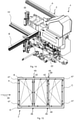
- the figure 3 shows the device 1 according to the invention with the two machining heads 4, 5, which can be moved along the rails 34, 35 in the direction of travel 6 or the direction of transport 20 along the workpiece 2.
- a processing unit 7 , 37 for processing the workpiece 2 is provided on each of the processing heads 4 , 5 .
- the processing units 7 , 37 can be moved in the positioning plane 9 running perpendicularly to the workpiece support plane 15 .
- the processing units 7, 37 move relative to the respective processing head 4, 5. In the present example, this movement takes place in the positioning directions 39, 40, which here correspond to the spatial directions X and Z. However, it is conceivable that the positioning directions 39, 40 do not coincide with the spatial directions X and Z.
- the travel rail 35 can be displaced in the spatial direction X, ie along the positioning plane 9 .
- the workpiece support 33 is also displaced together with the travel rail 35 .
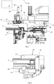
- the figure 4 shows an enlarged side view of the machining head 4, which implements a first variant of the invention.
- the processing unit 7 can be moved in the positioning plane 9 in the positioning directions 39 , 40 .
- the machining unit 7 is arranged on a tool holder 36, which is driven by a CNC axis unit 41 and is thus driven to be displaceable in the positioning direction 39 and with the CNC axis unit 38 and thus enables displaceability in the positioning direction 40.
- the machining unit 7 is held on the tool holder 36 such that it can be rotated about an axis of rotation 10 .
- a rotary axis drive 44 is provided, which is preferably position-controlled. Servo drives or stepper motor drives are particularly suitable for this.
- a clamping jaw device 26 or clamping roller device 27 is provided for holding the workpiece 2 figure 5 is explained in more detail.
- a clamping hook 19 for fixing the workpiece 2 in the direction of travel 6 is provided on the workpiece support 3 .
- a feed wrench 22 can be seen, the basis of figure 14 is explained in more detail.
- the figure 5 1 shows a clamping jaw device 26 which fixes the workpiece 2 in relation to the respective machining head 4, 5 in the positioning plane 9.
- several tensioning rollers are provided, which can act laterally on the workpiece 2, with two clamping jaws being provided here in the form of the tensioning roller device 27, which the workpiece 2 in the
- the tensioning roller 25 can be moved up to the workpiece 2 as a lateral stop. If required, a further tensioning roller in the form of the counter-stop 29 can also serve as a counterpart to the stop 25 .
- the figure 6 shows the machining head 4 during the machining of the workpiece 2, with the clamping jaw device or clamping roller device 26, 27 holding the workpiece 2. Furthermore, a transom 42 of the workpiece 2 or of the frame running transversely to the direction of travel 6 is indicated. When passing the fighter 42, the tensioning roller or counter-stop 29 must then be retracted on the inside of the workpiece 2 in order to avoid a collision between the counter-stop 29 and the fighter 42.
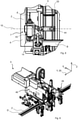
- figure 7 12 shows a more detailed view of the machining unit 7 attached to the tool holder 36.
- the machining unit 7 with its tool drive 43 can be rotated by the rotary axis drive 44 in such a way that a tool 8 arranged on the tool drive 43 can be aligned at an angle ⁇ .
- this angle should be at least 10° to 70° and 100° to 170° in order to enable drainage slots to be milled on the workpiece 2 .
- the processing unit 7 can preferably be positioned at any desired angle.
- the tool drive 43 carries two opposite machining tools 8, which are operated by the same drive and can be selectively or alternately directed at the workpiece 2 by rotating about the axis of rotation 10.
- the workpiece 2 being machined at a machining point 14 with one of the two machining tools 8 .
- the processing tool 8 that is not in use points away from the workpiece 2 .
- the machining unit 7 could simply be swiveled through 180° after the first hole has been drilled, so that the second machining tool 8 can then be aligned with the workpiece is.
- the figure 9 shows a second variant of the invention in the form of the processing head 5, which has a processing unit 37.
- This is not only rotatable about the axis of rotation 10 but also rotatable or pivotable about a vertical axis running in the spatial direction Z, with both axes being arranged on the tool holder 46 .
- the figure 10 shows the rotation or pivot axis 11 designed as a vertical axis, which in turn can be pivoted along the positioning direction 40, ie in the spatial direction Z.
- the machining tools 18 can be arranged in almost any orientation relative to the workpiece 2 .
- the one in the figure 10 The variant of the processing unit 37 shown differs from the previously described processing unit 7 on the processing head 4 only in that an additional pivot axis drive 45 is attached between the tool holder 46 and the processing unit 37, which also allows the processing unit 37 to be pivoted about the pivot axis 11.
- the figure 11 shows this processing unit 37 during the processing of a workpiece 2 on the profile bar C. It is easy to see that the same processing unit 37 can then also be aligned with the profile bar D by simply pivoting about the pivot axis 11 with its processing tool 18 .
- the ability to pivot about the pivot axis 11 should preferably be 90°.
- the pivot axis drive 45 is position-controlled and can be designed, for example, as a servo drive or else as a stepping motor drive.
- the figure 12 illustrates the special advantage of the device 1 according to the invention, which is particularly important for small workpieces 2, in which the processing unit 37 or processing unit 7 is not accessible to all areas of the workpiece 2.
- the processing unit 37 can do this Workpiece 2, i.e. also edit the frame on its far side.
- the processing unit 5 edits a processing point 14 in the vicinity of the section bar B.
- Both processing heads 4, 5 perform processing operations at different points on the workpiece 2 in the direction of travel 6, but are not allowed to meet or collide due to the small width of the workpiece.
- figure 13 shows how both processing heads 4, 5 process the same workpiece 2 at the same time.
- the figure 14 shows the processing head 4 with an additional unit for processing the workpiece 2 or the frame in the present exemplary embodiment.
- this unit is designed in the form of a feed screw driver 22 for producing a fighter screw connection.
- the additional unit can also be designed, for example, as a drill head and/or slot cutter and/or corner cleaning device and/or stop 25 and/or clamping jaw device 26 and/or tension roller device 27 and/or positioning gripper.
- a fighter 42 can be connected to the profile part B with the feed screw driver 22 .
- the feed screw driver 22 is arranged directly on the machining head 4 and separately from the tool holder 36 .
- a workpiece 2 in the form of a triple window frame is shown schematically, in which corner bearing bores 47 and shear bearing bores 48 have been introduced by the processing units 7, 37.
- drainage, venting or ventilation slots (not shown) can also be introduced into the frame.
- the already mentioned units additionally provided on the machining heads 4, 5, first to introduce bores and then fastening means for screw connections 49 in the transom.
- the fighters 42 are first inserted into the workpiece 2 between the profile bars B and D. This can preferably be done before the joining in the joining machine 16 or welding machine.
- a positioning means for example a positioning gripper, is provided on the device 1, preferably on at least one processing head 4, 5, which aligns the respective impost in particular in the longitudinal direction of the profile bars B, D, here in the transport direction 20.
- a fighter screw hole is set on the side of each profile bar B, D by an additional unit of the processing heads 4, 5, into which a fastening means for producing the fighter screw connection 49 is then driven by the feed screw driver 22.
- These processing steps can now take place in the device 1 in one run, so that any manual post-processing steps are no longer necessary. In one pass means that all processing steps take place before the workpiece is conveyed to the post-processing machine 17 .
Landscapes
- Life Sciences & Earth Sciences (AREA)
- Engineering & Computer Science (AREA)
- Mechanical Engineering (AREA)
- Wood Science & Technology (AREA)
- Forests & Forestry (AREA)
- Manufacturing & Machinery (AREA)
- Jigs For Machine Tools (AREA)
- Dovetailed Work, And Nailing Machines And Stapling Machines For Wood (AREA)
- Multi-Process Working Machines And Systems (AREA)
Claims (13)
- Dispositif (1), pour l'usinage mécanique de pièces allongées (2), sous forme de cadres ou de battants de fenêtres ou de portes ou de cadres dormants composés de barres profilées, comprenant une tête d'usinage (4, 5), la pièce à usiner (2) pouvant être agencée sur un support de pièce (3) et la pièce (2) ainsi que la tête d'usinage (4, 5) pouvant être déplacées l'une par rapport à l'autre sur le côté du support de pièce (3) pendant l'usinage de la pièce dans une direction de déplacement (6) le long du support de pièce (3), une unité d'usinage (7, 37) comprenant au moins un outil d'usinage (8, 18) maintenu sur celle-ci pour l'usinage de la pièce (2) étant agencée sur la tête d'usinage (4, 5) et pouvant être déplacée dans un plan de positionnement (9) s'étendant transversalement ou perpendiculairement à la direction de déplacement (6), et au moins un dispositif pour fixer la pièce (2) dans une ou deux directions de l'espace (X, Y, Z) sous la forme d'un dispositif à galets tendeurs entraîné (27) pour soutenir la pièce (2) pendant l'usinage de la pièce étant prévu sur la tête d'usinage (4, 5), caractérisé en ce que l'unité d'usinage (7, 37) peut être tournée et/ou pivotée par rapport à la tête d'usinage (4, 5) autour d'au moins un axe de rotation (10, 11) s'étendant transversalement ou perpendiculairement à la direction de déplacement (6) au moyen d'un entraînement, et en ce que l'unité d'usinage (7, 37) est configurée de manière à pouvoir se déplacer en translation dans le plan de positionnement (9) le long de l'au moins un axe de rotation (10, 11).
- Dispositif (1) selon la revendication 1, caractérisé en ce que l'unité d'usinage (7, 37) est configurée de manière à pouvoir tourner par rapport à la tête d'usinage (4, 5) autour d'au moins deux axes de rotation (10, 11) s'étendant transversalement ou perpendiculairement à la direction de déplacement (6) et transversalement ou perpendiculairement entre eux.
- Dispositif (1) selon la revendication 2, caractérisé en ce que l'unité d'usinage (7, 37) est configurée de manière à pouvoir se déplacer en translation dans le plan de positionnement (9) le long des deux axes de rotation (10, 11).
- Dispositif (1) selon l'une quelconque des revendications précédentes, caractérisé en ce qu'au moins un actionneur à position régulée, notamment un servo-entraînement (12), est prévu pour faire tourner l'unité d'usinage (7, 37) autour de l'au moins un axe de rotation (10, 11) et/ou pour décaler l'unité d'usinage (7, 37) le long d'au moins un des axes de rotation (10, 11).
- Dispositif (1) selon l'une quelconque des revendications précédentes, caractérisé en ce que l'au moins un axe de rotation (10) est orienté approximativement parallèlement à un plan de support de pièce (15) du support de pièce (3).
- Dispositif (1) selon l'une quelconque des revendications 1 à 4, caractérisé en ce que l'au moins un axe de rotation (11) est orienté approximativement perpendiculairement à un plan de support de pièce (15) du support de pièce (3).
- Dispositif (1) selon l'une quelconque des revendications précédentes, caractérisé en ce que l'unité d'usinage (7, 37) peut être orientée selon un angle d'usinage (0) d'environ 10° à environ 70° et/ou, de préférence, de 0° à environ 90°, défini par un plan de support de pièce (15) du support de pièce (3), notamment peut être orientée selon un angle quelconque compris entre 0° et 360°.
- Dispositif selon la revendication 7, caractérisé en ce que l'unité d'usinage (7, 37) peut en outre tourner autour d'un axe de rotation (11) configuré en tant qu'axe vertical.
- Dispositif (1) selon l'une quelconque des revendications précédentes, caractérisé en ce que l'unité d'usinage (7, 37) présente au moins deux outils d'usinage (8, 18) de préférence diamétralement opposés, qui peuvent être orientés alternativement sur un point d'usinage (14) de la pièce (2) par rotation de l'unité d'usinage (7, 37) autour de l'au moins un axe de rotation (10).
- Dispositif (1) selon l'une quelconque des revendications précédentes, caractérisé en ce que la tête d'usinage (4, 5) présente au moins une autre unité, de préférence indépendante de l'unité d'usinage (7, 37), pour l'usinage et/ou l'orientation et/ou le serrage de la pièce (2), l'unité étant configurée notamment sous forme de visseuse à avance (22) et/ou tête de forage (23) et/ou chanfrein à fente (24) et/ou dispositif de nettoyage des coins et/ou butée (25) et/ou dispositif à mâchoires de serrage (26) et dispositif à galets tendeurs et/ou pince de positionnement.
- Ligne d'usinage de profilés (30) pour l'usinage mécanique de pièces allongées (2) sous forme de barres profilées ou de cadres ou de battants de fenêtres ou de portes ou de cadres dormants composés de barres profilées, caractérisée en ce que la ligne d'usinage de profilés (30) présente un dispositif (1) selon l'une quelconque des revendications précédentes, il étant prévu que le dispositif (1) est prévu sous la forme d'une station de refroidissement (21), qui est placée en aval d'un dispositif de soudage (28) pour la fabrication de la pièce (2) et/ou en amont d'un dispositif d'usinage secondaire, notamment d'un dispositif de nettoyage des coins (31).
- Procédé d'usinage de pièces allongées (2), notamment de barres profilées ou de cadres ou de battants de fenêtres ou de portes ou de cadres dormants composés de barres profilées, caractérisé en ce que l'usinage est effectué avec un dispositif (1) selon l'une quelconque des revendications 1 à 10, notamment au moyen d'une ligne d'usinage de profilés (30) selon la revendication 11, aussi bien une fixation d'un élément de pièce supplémentaire, notamment d'une traverse (42), que son usinage mécanique s'effectuant de préférence en un seul passage.
- Procédé selon la revendication 12, caractérisé en ce que l'élément de pièce supplémentaire est aligné avec la pièce (2) avant d'être fixé à celle-ci, un usinage mécanique d'un point de fixation étant de préférence tout d'abord réalisé après l'alignement, notamment la mise en place d'un alésage pour le raccord vissé de la traverse (49), puis un moyen de fixation pour réaliser le raccord vissé de la traverse (49) étant enfoncé dans l'alésage.
Priority Applications (3)
| Application Number | Priority Date | Filing Date | Title |
|---|---|---|---|
| PL17154122T PL3357617T3 (pl) | 2017-02-01 | 2017-02-01 | Urządzenie do obróbki profili, odcinek obróbki profili i sposób |
| ES17154122T ES2910713T3 (es) | 2017-02-01 | 2017-02-01 | Dispositivo de procesamiento de perfiles, línea de procesamiento de perfiles y procedimiento |
| EP17154122.0A EP3357617B1 (fr) | 2017-02-01 | 2017-02-01 | Dispositif d'usinage de profilé, ligne d'usinage de profilé et procédé |
Applications Claiming Priority (1)
| Application Number | Priority Date | Filing Date | Title |
|---|---|---|---|
| EP17154122.0A EP3357617B1 (fr) | 2017-02-01 | 2017-02-01 | Dispositif d'usinage de profilé, ligne d'usinage de profilé et procédé |
Publications (2)
| Publication Number | Publication Date |
|---|---|
| EP3357617A1 EP3357617A1 (fr) | 2018-08-08 |
| EP3357617B1 true EP3357617B1 (fr) | 2022-02-23 |
Family
ID=57965714
Family Applications (1)
| Application Number | Title | Priority Date | Filing Date |
|---|---|---|---|
| EP17154122.0A Active EP3357617B1 (fr) | 2017-02-01 | 2017-02-01 | Dispositif d'usinage de profilé, ligne d'usinage de profilé et procédé |
Country Status (3)
| Country | Link |
|---|---|
| EP (1) | EP3357617B1 (fr) |
| ES (1) | ES2910713T3 (fr) |
| PL (1) | PL3357617T3 (fr) |
Families Citing this family (7)
| Publication number | Priority date | Publication date | Assignee | Title |
|---|---|---|---|---|
| CN109434214A (zh) * | 2018-12-19 | 2019-03-08 | 鹤山联塑实业发展有限公司 | 一种用于型材的加工设备 |
| CN110126029B (zh) * | 2019-06-27 | 2024-04-05 | 威力(烟台)木业技术有限公司 | 一种钻铣多工位加工装置 |
| CN111152015B (zh) * | 2020-01-17 | 2022-02-25 | 舒跃进 | 一种全自动的门板组装机 |
| CN112548180B (zh) * | 2021-01-30 | 2025-01-24 | 河南厚德电力科技有限公司 | 铝合金预埋槽道自动化生产线 |
| CN113857862A (zh) * | 2021-10-09 | 2021-12-31 | 山东雷德数控机械股份有限公司 | 一种门窗加工生产线及加工工艺 |
| CN117226151B (zh) * | 2023-09-18 | 2024-12-13 | 山东联兴智能设备有限公司 | 一种五轴数控端铣设备及其使用方法 |
| CN119304621B (zh) * | 2024-10-31 | 2025-05-23 | 湖北联投新材料开发有限公司 | 一种门窗自动化焊接制造系统及其应用方法 |
Family Cites Families (9)
| Publication number | Priority date | Publication date | Assignee | Title |
|---|---|---|---|---|
| DE3817005C2 (de) * | 1988-05-19 | 1996-07-11 | Hassomat Maschb Gmbh & Co Kg | Schweißmaschine zur Herstellung von Rahmen |
| DE4406381A1 (de) * | 1993-03-27 | 1994-09-29 | Volkmar Heuser | Maschine zur Bearbeitung von stabförmigen Werkstücken |
| AT404571B (de) * | 1995-07-11 | 1998-12-28 | Technoplast Kunststofftechnik | Programmgesteuerter manipulator |
| US6006408A (en) * | 1998-03-06 | 1999-12-28 | Wegoma, Inc. | Vinyl window frame weld seam cleaner |
| DE102006007171B4 (de) * | 2006-02-08 | 2014-12-31 | Elumatec Gmbh | Vorrichtung zum Bearbeiten von Eckverbindungen verschweißter Kunststoffprofile und Verfahren zum Bearbeiten von Eckverbindungen |
| IT1399223B1 (it) | 2010-03-16 | 2013-04-11 | Emmegi Spa | Apparato per lavorare cornici di infissi. |
| EP2460618B1 (fr) * | 2010-12-02 | 2013-03-06 | Hollinger Maschinen GmbH | Installation de fabrication et procédé de fabrication pour cadres de fenêtres ou de portes |
| EP3038806B1 (fr) * | 2013-08-29 | 2021-12-15 | GED Integrated Solutions, Inc. | Système et procédé de nettoyage de fenêtre |
| DE102013112814A1 (de) | 2013-11-20 | 2015-05-21 | Rotox Besitz-Und Verwaltungsgesellschaft Mbh | Eckverputzvorrichtung |
-
2017
- 2017-02-01 PL PL17154122T patent/PL3357617T3/pl unknown
- 2017-02-01 EP EP17154122.0A patent/EP3357617B1/fr active Active
- 2017-02-01 ES ES17154122T patent/ES2910713T3/es active Active
Also Published As
| Publication number | Publication date |
|---|---|
| ES2910713T3 (es) | 2022-05-13 |
| EP3357617A1 (fr) | 2018-08-08 |
| PL3357617T3 (pl) | 2022-06-13 |
Similar Documents
| Publication | Publication Date | Title |
|---|---|---|
| EP3357617A1 (fr) | Machine d'usinage de profilé et ligne d'usinage de profilé | |
| DE3823635C2 (fr) | ||
| EP1281491B1 (fr) | Dispositif et procédé pour travailler des pièces à usiner en bois, plastique ou similaires | |
| EP3639971B1 (fr) | Procédé de traitement des pièces longues en bois, en matière plastique et analogue, ainsi que machine permettant de mettre en oeuvre ledit procédé | |
| EP0922547A2 (fr) | Dispositif pour la fabrication de châssis de fenêtres | |
| EP0683297A1 (fr) | Procédé de montage assisté par automate des ferrures sur une aile d'une fenêtre, porte ou similaire | |
| DE3521350A1 (de) | Vorrichtung zur bearbeitung von pfosten oder sprossen fuer fenster oder tueren | |
| AT514821B1 (de) | Biegepresse und Biegeverfahren | |
| EP2678133A1 (fr) | Dispositif de serrage pour pièces en bois, en plastique ou similaire | |
| EP1338404B1 (fr) | Dispositif et procédé pour souder des profilés en matière plastique | |
| EP4117837A1 (fr) | Presse plieuse | |
| EP3031547A1 (fr) | Procede et dispositif de fabrication d'un raccord d'angle | |
| EP0925868A2 (fr) | Dispositif de fabrication de châssis de fenêtres | |
| DE102007014532A1 (de) | Vorrichtung zum Bearbeiten des Eckbereichs von aus Profilstücken geschweißten Rahmen | |
| DE602006000992T2 (de) | Maschine zur Herstellung von Türrahmen | |
| DE3203025C2 (fr) | ||
| DE69008120T2 (de) | Vorrichtung zur stufenweisen Positionierung, Bearbeitung und Nachbehandlung von Ecken von aus Kunststoff hergestellten Fenster- oder Türrahmen in einer seitlich angeordneten Arbeitsstelle. | |
| EP2105282A2 (fr) | Dispositif et procédé de liaison d'éléments de profilés d'un cadre de fenêtre ou de porte | |
| EP3238876B1 (fr) | Dispositif de traitement de pieces usinees en forme de tiges telles que profiles de fenetre ou de porte | |
| DE19621667C2 (de) | Vorrichtung zum Zuschneiden von Rahmenteilen | |
| DE3817005C2 (de) | Schweißmaschine zur Herstellung von Rahmen | |
| DE19725043A1 (de) | Vorrichtung zum Bearbeiten von Bauelementen | |
| DE10115653B4 (de) | Spannsystem zum Spannen und ggf. Zentrieren von Profilrahmen in Kombination mit einer Putzvorrichtung mit wenigstens zwei Bearbeitungseinheiten und zugehöriges Verfahren | |
| DE10033705C2 (de) | Vorrichtung zum Bearbeiten von langgestreckten Werkstücken, insbesondere von Fenster- und Türeneinzelteilen | |
| EP3705672B1 (fr) | Outil pour le montage des paumelles sur des profilés de construction |
Legal Events
| Date | Code | Title | Description |
|---|---|---|---|
| PUAI | Public reference made under article 153(3) epc to a published international application that has entered the european phase |
Free format text: ORIGINAL CODE: 0009012 |
|
| STAA | Information on the status of an ep patent application or granted ep patent |
Free format text: STATUS: THE APPLICATION HAS BEEN PUBLISHED |
|
| AK | Designated contracting states |
Kind code of ref document: A1 Designated state(s): AL AT BE BG CH CY CZ DE DK EE ES FI FR GB GR HR HU IE IS IT LI LT LU LV MC MK MT NL NO PL PT RO RS SE SI SK SM TR |
|
| AX | Request for extension of the european patent |
Extension state: BA ME |
|
| STAA | Information on the status of an ep patent application or granted ep patent |
Free format text: STATUS: REQUEST FOR EXAMINATION WAS MADE |
|
| 17P | Request for examination filed |
Effective date: 20190207 |
|
| RBV | Designated contracting states (corrected) |
Designated state(s): AL AT BE BG CH CY CZ DE DK EE ES FI FR GB GR HR HU IE IS IT LI LT LU LV MC MK MT NL NO PL PT RO RS SE SI SK SM TR |
|
| STAA | Information on the status of an ep patent application or granted ep patent |
Free format text: STATUS: EXAMINATION IS IN PROGRESS |
|
| 17Q | First examination report despatched |
Effective date: 20200723 |
|
| RIC1 | Information provided on ipc code assigned before grant |
Ipc: B27M 3/00 20060101ALI20210930BHEP Ipc: B27M 1/08 20060101ALI20210930BHEP Ipc: B27C 9/04 20060101ALI20210930BHEP Ipc: B23Q 1/48 20060101ALI20210930BHEP Ipc: B23P 23/02 20060101ALI20210930BHEP Ipc: B23C 3/12 20060101AFI20210930BHEP |
|
| GRAP | Despatch of communication of intention to grant a patent |
Free format text: ORIGINAL CODE: EPIDOSNIGR1 |
|
| STAA | Information on the status of an ep patent application or granted ep patent |
Free format text: STATUS: GRANT OF PATENT IS INTENDED |
|
| INTG | Intention to grant announced |
Effective date: 20211215 |
|
| GRAS | Grant fee paid |
Free format text: ORIGINAL CODE: EPIDOSNIGR3 |
|
| GRAA | (expected) grant |
Free format text: ORIGINAL CODE: 0009210 |
|
| STAA | Information on the status of an ep patent application or granted ep patent |
Free format text: STATUS: THE PATENT HAS BEEN GRANTED |
|
| AK | Designated contracting states |
Kind code of ref document: B1 Designated state(s): AL AT BE BG CH CY CZ DE DK EE ES FI FR GB GR HR HU IE IS IT LI LT LU LV MC MK MT NL NO PL PT RO RS SE SI SK SM TR |
|
| REG | Reference to a national code |
Ref country code: GB Ref legal event code: FG4D Free format text: NOT ENGLISH |
|
| REG | Reference to a national code |
Ref country code: CH Ref legal event code: EP |
|
| REG | Reference to a national code |
Ref country code: DE Ref legal event code: R096 Ref document number: 502017012620 Country of ref document: DE |
|
| REG | Reference to a national code |
Ref country code: AT Ref legal event code: REF Ref document number: 1470048 Country of ref document: AT Kind code of ref document: T Effective date: 20220315 |
|
| REG | Reference to a national code |
Ref country code: IE Ref legal event code: FG4D Free format text: LANGUAGE OF EP DOCUMENT: GERMAN |
|
| REG | Reference to a national code |
Ref country code: NL Ref legal event code: FP |
|
| REG | Reference to a national code |
Ref country code: ES Ref legal event code: FG2A Ref document number: 2910713 Country of ref document: ES Kind code of ref document: T3 Effective date: 20220513 |
|
| REG | Reference to a national code |
Ref country code: LT Ref legal event code: MG9D |
|
| PG25 | Lapsed in a contracting state [announced via postgrant information from national office to epo] |
Ref country code: SE Free format text: LAPSE BECAUSE OF FAILURE TO SUBMIT A TRANSLATION OF THE DESCRIPTION OR TO PAY THE FEE WITHIN THE PRESCRIBED TIME-LIMIT Effective date: 20220223 Ref country code: RS Free format text: LAPSE BECAUSE OF FAILURE TO SUBMIT A TRANSLATION OF THE DESCRIPTION OR TO PAY THE FEE WITHIN THE PRESCRIBED TIME-LIMIT Effective date: 20220223 Ref country code: PT Free format text: LAPSE BECAUSE OF FAILURE TO SUBMIT A TRANSLATION OF THE DESCRIPTION OR TO PAY THE FEE WITHIN THE PRESCRIBED TIME-LIMIT Effective date: 20220623 Ref country code: NO Free format text: LAPSE BECAUSE OF FAILURE TO SUBMIT A TRANSLATION OF THE DESCRIPTION OR TO PAY THE FEE WITHIN THE PRESCRIBED TIME-LIMIT Effective date: 20220523 Ref country code: LT Free format text: LAPSE BECAUSE OF FAILURE TO SUBMIT A TRANSLATION OF THE DESCRIPTION OR TO PAY THE FEE WITHIN THE PRESCRIBED TIME-LIMIT Effective date: 20220223 Ref country code: HR Free format text: LAPSE BECAUSE OF FAILURE TO SUBMIT A TRANSLATION OF THE DESCRIPTION OR TO PAY THE FEE WITHIN THE PRESCRIBED TIME-LIMIT Effective date: 20220223 Ref country code: BG Free format text: LAPSE BECAUSE OF FAILURE TO SUBMIT A TRANSLATION OF THE DESCRIPTION OR TO PAY THE FEE WITHIN THE PRESCRIBED TIME-LIMIT Effective date: 20220523 |
|
| PG25 | Lapsed in a contracting state [announced via postgrant information from national office to epo] |
Ref country code: LV Free format text: LAPSE BECAUSE OF FAILURE TO SUBMIT A TRANSLATION OF THE DESCRIPTION OR TO PAY THE FEE WITHIN THE PRESCRIBED TIME-LIMIT Effective date: 20220223 Ref country code: GR Free format text: LAPSE BECAUSE OF FAILURE TO SUBMIT A TRANSLATION OF THE DESCRIPTION OR TO PAY THE FEE WITHIN THE PRESCRIBED TIME-LIMIT Effective date: 20220524 Ref country code: FI Free format text: LAPSE BECAUSE OF FAILURE TO SUBMIT A TRANSLATION OF THE DESCRIPTION OR TO PAY THE FEE WITHIN THE PRESCRIBED TIME-LIMIT Effective date: 20220223 |
|
| PG25 | Lapsed in a contracting state [announced via postgrant information from national office to epo] |
Ref country code: IS Free format text: LAPSE BECAUSE OF FAILURE TO SUBMIT A TRANSLATION OF THE DESCRIPTION OR TO PAY THE FEE WITHIN THE PRESCRIBED TIME-LIMIT Effective date: 20220623 |
|
| PG25 | Lapsed in a contracting state [announced via postgrant information from national office to epo] |
Ref country code: SM Free format text: LAPSE BECAUSE OF FAILURE TO SUBMIT A TRANSLATION OF THE DESCRIPTION OR TO PAY THE FEE WITHIN THE PRESCRIBED TIME-LIMIT Effective date: 20220223 Ref country code: SK Free format text: LAPSE BECAUSE OF FAILURE TO SUBMIT A TRANSLATION OF THE DESCRIPTION OR TO PAY THE FEE WITHIN THE PRESCRIBED TIME-LIMIT Effective date: 20220223 Ref country code: RO Free format text: LAPSE BECAUSE OF FAILURE TO SUBMIT A TRANSLATION OF THE DESCRIPTION OR TO PAY THE FEE WITHIN THE PRESCRIBED TIME-LIMIT Effective date: 20220223 Ref country code: EE Free format text: LAPSE BECAUSE OF FAILURE TO SUBMIT A TRANSLATION OF THE DESCRIPTION OR TO PAY THE FEE WITHIN THE PRESCRIBED TIME-LIMIT Effective date: 20220223 Ref country code: DK Free format text: LAPSE BECAUSE OF FAILURE TO SUBMIT A TRANSLATION OF THE DESCRIPTION OR TO PAY THE FEE WITHIN THE PRESCRIBED TIME-LIMIT Effective date: 20220223 Ref country code: CZ Free format text: LAPSE BECAUSE OF FAILURE TO SUBMIT A TRANSLATION OF THE DESCRIPTION OR TO PAY THE FEE WITHIN THE PRESCRIBED TIME-LIMIT Effective date: 20220223 |
|
| REG | Reference to a national code |
Ref country code: DE Ref legal event code: R097 Ref document number: 502017012620 Country of ref document: DE |
|
| PG25 | Lapsed in a contracting state [announced via postgrant information from national office to epo] |
Ref country code: AL Free format text: LAPSE BECAUSE OF FAILURE TO SUBMIT A TRANSLATION OF THE DESCRIPTION OR TO PAY THE FEE WITHIN THE PRESCRIBED TIME-LIMIT Effective date: 20220223 |
|
| PLBE | No opposition filed within time limit |
Free format text: ORIGINAL CODE: 0009261 |
|
| STAA | Information on the status of an ep patent application or granted ep patent |
Free format text: STATUS: NO OPPOSITION FILED WITHIN TIME LIMIT |
|
| 26N | No opposition filed |
Effective date: 20221124 |
|
| PG25 | Lapsed in a contracting state [announced via postgrant information from national office to epo] |
Ref country code: SI Free format text: LAPSE BECAUSE OF FAILURE TO SUBMIT A TRANSLATION OF THE DESCRIPTION OR TO PAY THE FEE WITHIN THE PRESCRIBED TIME-LIMIT Effective date: 20220223 |
|
| P01 | Opt-out of the competence of the unified patent court (upc) registered |
Effective date: 20230530 |
|
| PG25 | Lapsed in a contracting state [announced via postgrant information from national office to epo] |
Ref country code: MC Free format text: LAPSE BECAUSE OF FAILURE TO SUBMIT A TRANSLATION OF THE DESCRIPTION OR TO PAY THE FEE WITHIN THE PRESCRIBED TIME-LIMIT Effective date: 20220223 |
|
| REG | Reference to a national code |
Ref country code: CH Ref legal event code: PL |
|
| PG25 | Lapsed in a contracting state [announced via postgrant information from national office to epo] |
Ref country code: LU Free format text: LAPSE BECAUSE OF NON-PAYMENT OF DUE FEES Effective date: 20230201 Ref country code: LI Free format text: LAPSE BECAUSE OF NON-PAYMENT OF DUE FEES Effective date: 20230228 Ref country code: CH Free format text: LAPSE BECAUSE OF NON-PAYMENT OF DUE FEES Effective date: 20230228 |
|
| REG | Reference to a national code |
Ref country code: IE Ref legal event code: MM4A |
|
| PG25 | Lapsed in a contracting state [announced via postgrant information from national office to epo] |
Ref country code: IE Free format text: LAPSE BECAUSE OF NON-PAYMENT OF DUE FEES Effective date: 20230201 |
|
| PGFP | Annual fee paid to national office [announced via postgrant information from national office to epo] |
Ref country code: NL Payment date: 20250218 Year of fee payment: 9 |
|
| PGFP | Annual fee paid to national office [announced via postgrant information from national office to epo] |
Ref country code: AT Payment date: 20250219 Year of fee payment: 9 Ref country code: BE Payment date: 20250218 Year of fee payment: 9 |
|
| PGFP | Annual fee paid to national office [announced via postgrant information from national office to epo] |
Ref country code: FR Payment date: 20250221 Year of fee payment: 9 |
|
| PGFP | Annual fee paid to national office [announced via postgrant information from national office to epo] |
Ref country code: GB Payment date: 20250220 Year of fee payment: 9 |
|
| PGFP | Annual fee paid to national office [announced via postgrant information from national office to epo] |
Ref country code: ES Payment date: 20250331 Year of fee payment: 9 |
|
| PG25 | Lapsed in a contracting state [announced via postgrant information from national office to epo] |
Ref country code: CY Free format text: LAPSE BECAUSE OF FAILURE TO SUBMIT A TRANSLATION OF THE DESCRIPTION OR TO PAY THE FEE WITHIN THE PRESCRIBED TIME-LIMIT; INVALID AB INITIO Effective date: 20170201 |
|
| PG25 | Lapsed in a contracting state [announced via postgrant information from national office to epo] |
Ref country code: HU Free format text: LAPSE BECAUSE OF FAILURE TO SUBMIT A TRANSLATION OF THE DESCRIPTION OR TO PAY THE FEE WITHIN THE PRESCRIBED TIME-LIMIT; INVALID AB INITIO Effective date: 20170201 |
|
| PG25 | Lapsed in a contracting state [announced via postgrant information from national office to epo] |
Ref country code: TR Free format text: LAPSE BECAUSE OF FAILURE TO SUBMIT A TRANSLATION OF THE DESCRIPTION OR TO PAY THE FEE WITHIN THE PRESCRIBED TIME-LIMIT Effective date: 20220223 |
|
| PGFP | Annual fee paid to national office [announced via postgrant information from national office to epo] |
Ref country code: DE Payment date: 20260228 Year of fee payment: 10 |
|
| PGFP | Annual fee paid to national office [announced via postgrant information from national office to epo] |
Ref country code: IT Payment date: 20260224 Year of fee payment: 10 |
|
| PGFP | Annual fee paid to national office [announced via postgrant information from national office to epo] |
Ref country code: PL Payment date: 20260123 Year of fee payment: 10 |