EP3357699A1 - Imprimante et procédé d'impression - Google Patents
Imprimante et procédé d'impression Download PDFInfo
- Publication number
- EP3357699A1 EP3357699A1 EP18155005.4A EP18155005A EP3357699A1 EP 3357699 A1 EP3357699 A1 EP 3357699A1 EP 18155005 A EP18155005 A EP 18155005A EP 3357699 A1 EP3357699 A1 EP 3357699A1
- Authority
- EP
- European Patent Office
- Prior art keywords
- medium
- colored ink
- printing
- functional liquid
- printing apparatus
- Prior art date
- Legal status (The legal status is an assumption and is not a legal conclusion. Google has not performed a legal analysis and makes no representation as to the accuracy of the status listed.)
- Granted
Links
Images

Classifications
-
- B—PERFORMING OPERATIONS; TRANSPORTING
- B41—PRINTING; LINING MACHINES; TYPEWRITERS; STAMPS
- B41J—TYPEWRITERS; SELECTIVE PRINTING MECHANISMS, i.e. MECHANISMS PRINTING OTHERWISE THAN FROM A FORME; CORRECTION OF TYPOGRAPHICAL ERRORS
- B41J2/00—Typewriters or selective printing mechanisms characterised by the printing or marking process for which they are designed
- B41J2/005—Typewriters or selective printing mechanisms characterised by the printing or marking process for which they are designed characterised by bringing liquid or particles selectively into contact with a printing material
- B41J2/01—Ink jet
- B41J2/21—Ink jet for multi-colour printing
-
- B—PERFORMING OPERATIONS; TRANSPORTING
- B41—PRINTING; LINING MACHINES; TYPEWRITERS; STAMPS
- B41J—TYPEWRITERS; SELECTIVE PRINTING MECHANISMS, i.e. MECHANISMS PRINTING OTHERWISE THAN FROM A FORME; CORRECTION OF TYPOGRAPHICAL ERRORS
- B41J11/00—Devices or arrangements of selective printing mechanisms, e.g. ink-jet printers or thermal printers, for supporting or handling copy material in sheet or web form
- B41J11/007—Conveyor belts or like feeding devices
-
- B—PERFORMING OPERATIONS; TRANSPORTING
- B41—PRINTING; LINING MACHINES; TYPEWRITERS; STAMPS
- B41J—TYPEWRITERS; SELECTIVE PRINTING MECHANISMS, i.e. MECHANISMS PRINTING OTHERWISE THAN FROM A FORME; CORRECTION OF TYPOGRAPHICAL ERRORS
- B41J2/00—Typewriters or selective printing mechanisms characterised by the printing or marking process for which they are designed
- B41J2/005—Typewriters or selective printing mechanisms characterised by the printing or marking process for which they are designed characterised by bringing liquid or particles selectively into contact with a printing material
- B41J2/01—Ink jet
- B41J2/21—Ink jet for multi-colour printing
- B41J2/2107—Ink jet for multi-colour printing characterised by the ink properties
- B41J2/2114—Ejecting specialized liquids, e.g. transparent or processing liquids
-
- B—PERFORMING OPERATIONS; TRANSPORTING
- B41—PRINTING; LINING MACHINES; TYPEWRITERS; STAMPS
- B41J—TYPEWRITERS; SELECTIVE PRINTING MECHANISMS, i.e. MECHANISMS PRINTING OTHERWISE THAN FROM A FORME; CORRECTION OF TYPOGRAPHICAL ERRORS
- B41J3/00—Typewriters or selective printing or marking mechanisms characterised by the purpose for which they are constructed
- B41J3/407—Typewriters or selective printing or marking mechanisms characterised by the purpose for which they are constructed for marking on special material
- B41J3/4078—Printing on textile
Definitions
- the present invention relates to a printing apparatus and a printing method.
- JP-A-2009-17133 describes an image processing method for computation of dither and randomization of dither by quantization processing, in which the image processing method follows quantization processing independently to dot ON/OFF determination.
- a printing apparatus is a printing apparatus that includes a head capable of discharging liquids toward a medium, with the liquids including a colored ink and a functional liquid that promotes penetration of the colored ink.
- the printing apparatus includes a normal mode to print a front face of the medium with the colored ink, and a bleed-through mode to print the front and reverse of the medium by printing the front face of the medium with the colored ink and using the functional liquid to cause the discharged colored ink to penetrate toward the reverse face of the medium.
- the colored ink and the functional liquid are used for forming in regions having a specific lightness or greater.
- the printing apparatus uses the colored ink and the functional liquid for forming in regions having the specific lightness or greater in normal mode.
- the regions having the specific lightness or greater have only a small colored ink discharge amount, and so there is worse graininess, in which portions of the medium are not dyed and dots formed on the medium are visible as spots.
- the functional liquid is discharged in addition to the colored ink in the regions having the specific lightness or greater, and so the colored ink soaks into and wets out the surface of the medium. This enables the graininess of the regions having the specific lightness or greater to be ameliorated.
- the printing apparatus includes an input unit, wherein the specific lightness can be changed by input through the input unit.
- the printing apparatus includes the input unit for input of print conditions and the like by a user.
- the visibility of graininess differs according to the type of medium.
- the specific lightness can be changed by input through the input unit for the highlight areas where the functional liquid is to be discharged so as to ameliorate graininess, and this enables the graininess to be ameliorated for a wide variety of media.
- a discharge amount of the functional liquid to be discharged on regions of the specific lightness or greater can be changed by input through the input unit.
- the discharge amount of the functional liquid to be discharged in order to ameliorate the graininess of the regions having the specific lightness or greater can be changed by input operation to the input unit by a user. This enables fine adjustment to the degree of graininess amelioration based on a printed image.
- a printing apparatus includes a head capable of discharging liquids toward a medium, with the liquids including a colored ink and a functional liquid that promotes penetration of the colored ink.
- the printing apparatus includes a normal mode to print a front face of the medium with the colored ink, and a bleed-through mode to print the front and reverse of the medium by printing the front face of the medium with the colored ink and using the functional liquid to cause the discharged colored ink to penetrate toward the reverse face of the medium.
- the functional liquid is discharged onto regions in which a discharge amount of the colored ink is less than a specific value.
- the printing apparatus discharges functional liquid onto regions where the colored ink discharge amount in the normal mode is less than the specific value.
- the functional liquid is discharged onto these regions, and so the colored ink soaks into and wets out the surface of the medium. This enables graininess to be ameliorated in the regions where the colored ink discharge amount is less than the specific value.
- the printing apparatus includes an input unit, and the specific value can be changed by input through the input unit.
- the input unit for input of print conditions and the like by a user is included. Visibility of graininess differs according to the type of medium, however, the graininess is ameliorated by discharging the functional liquid.
- the regions where the colored ink discharge amount is less than the specific value can be changed by the specific value being input through the input unit, thereby enabling graininess to be ameliorated for a wide variety of media.
- a printing method is a printing method for a printing apparatus including a head capable of discharging liquids toward a medium.
- the liquids include a colored ink and a functional liquid that promotes penetration of the colored ink.
- the printing apparatus includes a normal mode to print a front face of the medium with the colored ink, and a bleed-through mode to print the front and reverse of the medium by printing the front face of the medium with the colored ink and using the functional liquid to cause the discharged colored ink to penetrate toward the reverse face of the medium.
- the printing method includes, when printing in the normal mode: a region determination process that determines whether or not a region has a specific lightness or greater; and a discharge condition change process that changes a discharge condition for a region having the specific lightness or greater from a discharge condition to discharge the colored ink to a discharge condition to discharge the colored ink and the functional liquid.
- a region determination process that determines whether or not a region has a specific lightness or greater
- a discharge condition change process that changes a discharge condition for a region having the specific lightness or greater from a discharge condition to discharge the colored ink alone to a discharge condition to discharge the colored ink and the functional liquid
- the highlight areas only have a small colored ink discharge amount, and so there is worse graininess, in which portions of the medium are not dyed and dots formed on the medium are visible as spots.
- discharge is performed by a discharge condition to discharge the colored ink and the functional liquid, so that the colored ink soaks into and wets out the surface of the medium. This enables the graininess of the regions having the specific lightness or greater to be ameliorated.
- the discharge condition change process of the printing method is changed based on the lightness.
- the discharge condition is changed based on the lightness. More precisely, the discharge condition for the colored ink and the functional liquid is changed to a discharge condition that obtains substantially the same lightness to the lightness that would be obtained when the colored ink alone is discharged. This enables graininess to be ameliorated while also reproducing a color of substantially the same brightness (lightness).
- an X axis, a Y axis, and a Z axis are illustrated as three mutually orthogonal axes in Fig. 1 , with arrows illustrating the directions of these axes each having a leading end side indicating a "+ side", and having a base end side indicating a "- side”.
- Directions parallel to the X axis are referred to as "X axis directions”
- directions parallel to the Y axis are referred to as "Y axis directions”
- directions parallel to the Z axis are referred to as "Z axis directions”.
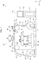
- Fig. 1 is a schematic diagram illustrating an overall schematic configuration of a printing apparatus according to a first embodiment.
- a schematic configuration of a printing apparatus 100 according to the present embodiment will be described, with reference to Fig. 1 .
- the printing apparatus 100 includes an image processing device 110 that is input with various print conditions and generates print data.
- the image processing device 110 includes a printer controller 111, an input section 112, a display section 113, and the like.
- the printer controller 111 controls the input section 112 and the display section 113, and performs print job control to perform printing with the printing apparatus 100.
- the printer controller 111 performs overall control of the printing apparatus 100 in coordination with a controller 1 of the printing apparatus 100.
- the display section 113 is configured by, for example, a liquid crystal display. Various information is displayed on the display section 113.
- the input section 112 is configured by various hardware keys, a touch panel provided on the front face of the display section 113 (liquid crystal display), or the like.
- the display section 113 displays selection options for various commands using graphical user interface (GUI) buttons or the like, and a user inputs the various commands by selecting commands using the input section 112.
- GUI graphical user interface
- the printing apparatus 100 also includes a medium transport unit 20, a medium adhering unit 60, a printing unit 40, a drying unit 27, a cleaning unit 50, and the like.
- the printing apparatus 100 is provided with the controller 1 to control these units.
- Each of the units of the printing apparatus 100 is attached to a frame unit 92.
- the medium transport unit 20 transports the medium 95 along a transport direction (the +X axis direction in the printing unit 40).
- the medium transport unit 20 includes a medium feed unit 10, transport rollers 21, 22, a transport belt 23, a belt rotation roller 24, a belt drive roller 25, transport rollers 26, 28, and a medium collection unit 30.
- a transport path of the medium 95 from the medium feed unit 10 to the medium collection unit 30 is the direction of gravity is the Z axis
- the direction the medium 95 is transported in the printing unit 40 is the X axis
- a width direction of the medium 95 intersecting with both the Z axis and the X axis is the Y axis.
- the medium feed unit 10 feeds the medium 95 to form an image on to the printing unit 40.
- a woven fabric or nonwoven fabric formed from natural fibers, cotton, silk, flax, mohair, wool, Kashmir, recycled fibers, synthetic fibers, nylon, polyurethane, polyester, and mixtures thereof, for example, may be employed as the medium 95.
- the woven fabric and the nonwoven fabric may be coated with a pretreatment agent in order to enhance color development and adhesion properties.
- the medium feed unit 10 includes a feed shaft 11 and shaft bearings 12.
- the feed shaft 11 is formed in a cylindrical tube or circular bar shape, and is provided so as to be rotatable in a circumferential direction.
- the strip shaped medium 95 is wound in roll form around the feed shaft 11.
- the feed shaft 11 is detachably mounted to the shaft bearings 12. This enables the medium 95 in a pre-wound state on the feed shaft 11 to be mounted to the shaft bearings 12 together with the feed shaft 11.
- the take-up direction and the rotation direction of the medium 95 retained on the feed shaft 11 are merely examples thereof, and there is no limitation thereto.
- a configuration may be adopted in which the feed shaft 11 is rotated in the opposite direction so as to feed out a medium 95 from a roll that has been wound with a recording face of the medium 95 on the inside.
- the shaft bearings 12 rotatably support the two axial direction ends of the feed shaft 11.
- the medium feed unit 10 includes a rotational drive unit (not illustrated in the drawings) to rotationally drive the feed shaft 11.
- the rotational drive unit rotates the feed shaft 11 in a direction to feed out the medium 95.
- the operation of the rotational drive unit is controlled by the controller 1.
- the transport rollers 21, 22 relay the medium 95 from the medium feed unit 10 to the transport belt 23.
- the transport belt 23 transports the medium 95 in the transport direction (+X axis direction).
- the transport belt 23 is formed in an endless belt shape in which the two ends of a strip shaped belt are connected together, and the transport belt 23 is threaded on the belt rotation roller 24 and the belt drive roller 25.
- the transport belt 23 is held in a state in which a predetermined tension acts such that the portion of the transport belt 23 between the belt rotation roller 24 and the belt drive roller 25 is parallel to a floor surface 99.
- An adhesive layer 29 to adhere the medium 95 is provided on a front face (support face) 23a of the transport belt 23.
- the transport belt 23 supports (retains) the medium 95 fed from the transport roller 22 and adhered to the adhesive layer 29 by the medium adhering unit 60, described later. This enables stretchable fabrics and the like to be employed as the medium 95.
- the belt rotation roller 24 and the belt drive roller 25 support the inner peripheral face 23b of the transport belt 23. Note that a configuration may be adopted in which a support section to support the transport belt 23 is provided between the belt rotation roller 24 and the belt drive roller 25.
- the belt drive roller 25 includes a motor (not illustrated in the drawings) to rotationally drive the belt drive roller 25.
- a motor not illustrated in the drawings to rotationally drive the belt drive roller 25.
- the transport belt 23 is rotated accompanying rotation of the belt drive roller 25, and the belt rotation roller 24 is rotated by the rotation of the transport belt 23.
- the medium 95 supported by the transport belt 23 is transported in the predetermined transport direction (the +X axis direction) by the rotation of the transport belt 23, and an image is formed on the medium 95 by the printing unit 40, as described later.
- the transport belt 23 on the side where the front face 23a of the transport belt 23 faces the printing unit 40 (the +Z axis side), the medium 95 is supported thereon and the medium 95 is transported together with the transport belt 23 from the belt rotation roller 24 side to the belt drive roller 25 side (in the +X axis direction). Moreover, on the side where the front face 23a of the transport belt 23 faces the cleaning unit 50 (the -Z axis side), the transport belt 23 alone is moved from the belt drive roller 25 side to the belt rotation roller 24 side (in the -X axis direction).
- the transport belt 23 is described as having the adhesive layer 29 to adhere the medium 95, there is no limitation thereto.
- the transport belt may be an electrostatic transport belt that adheres the medium to a belt electrostatically.
- the transport roller 26 releases the image-formed medium 95 from the adhesive layer 29 of the transport belt 23.
- the transport rollers 26, 28 relay the medium 95 from the transport belt 23 to the medium collection unit 30.
- the medium collection unit 30 collects the medium 95 transported by the medium transport unit 20.
- the medium collection unit 30 includes a take-up shaft 31 and shaft bearings 32.
- the take-up shaft 31 is formed in a cylindrical tube or circular bar shape, and is provided so as to be rotatable in a circumferential direction.
- the strip shaped medium 95 is taken up in a roll shape on the take-up shaft 31.
- the take-up shaft 31 is detachably mounted to the shaft bearings 32. The medium 95 in a state taken up on the take-up shaft 31 can thereby be removed together with the take-up shaft 31.
- the shaft bearings 32 rotatably support the two axial direction ends of the feed shaft 31.
- the medium collection unit 30 includes a rotational drive unit (not illustrated in the drawings) to rotationally drive the take-up shaft 31.
- the rotational drive unit rotates the take-up shaft 31 in the direction to take-up the medium 95.
- the operation of the rotational drive unit is controlled by the controller 1. Note that the take-up direction and the rotation direction of the medium 95 retained on the medium collection unit 30 illustrated in Fig. 1 are merely examples thereof, and there is no limitation thereto. A configuration may be adopted in which the take-up shaft 31 is rotated in the opposite direction, and the medium 95 is taken up with the recording face on the inside.
- the medium adhering unit 60 adheres the medium 95 to the transport belt 23.
- the medium adhering unit 60 is provided upstream (on the -X axis side) of the printing unit 40.
- the medium adhering unit 60 includes a press roller 61, a press roller driver 62, and a roller support 63.
- the press roller 61 is formed in a cylindrical tube or circular bar shape, and is provided so as to be rotatable in a circumferential direction.
- the press roller 61 is disposed with its axial direction intersecting with the transport direction, so as to rotate in a direction along the transport direction.
- the roller support 63 is provided on the inner peripheral face 23b side of the transport belt 23, so as to face the press roller 61 across the transport belt 23.
- the press roller driver 62 moves the press roller 61 in the transport direction (the +X axis direction), and in the opposite direction to the transport direction (the -X axis direction).
- the medium 95 superimposed on the transport belt 23 is pressed against the transport belt 23 between the press roller 61 and the roller support 63. This enables the medium 95 to be reliably adhered to the adhesive layer 29 provided on the front face 23a of the transport belt 23, and enables the medium 95 to be prevented from lifting up off the transport belt 23.
- the drying unit 27 is provided between the transport roller 26 and the transport roller 28.
- the drying unit 27 dries ink discharged onto the medium 95.
- the drying unit 27 includes, for example, an IR heater, and ink that has been discharged onto the medium 95 can be dried in a short period of time by driving the IR heater. This enables the strip shaped medium 95 formed with an image or the like to be taken up on the take-up shaft 31.
- the cleaning unit 50 cleans the transport belt 23.
- the cleaning unit 50 is configured by a cleaning section 51, a pressing section 52, and a moving section 53.
- the moving section 53 moves the cleaning unit 50 as an integrated unit along the floor surface 99, and is able to fix the cleaning unit 50 at a predetermined position.
- the cleaning unit 50 is disposed between the belt rotation roller 24 and the belt drive roller 25 in the X axis direction.
- the pressing section 52 is, for example, a raising-lowering device configured by air cylinders 56 and ball bushings 57, and is able to move the cleaning section 51 provided above the pressing section 52 to a cleaning position and a retracted position.
- the cleaning position is a position where a cleaning roller 58 and a blade 55 contact the transport belt 23.
- the retracted position is a position where the cleaning roller 58 and the blade 55 are separated from the transport belt 23.
- the cleaning section 51 cleans the front face 23a (support face) of the transport belt 23 from below (the -Z axis direction) at the cleaning position, in a state in which a predetermined tension acts on the transport belt 23 entrained between the belt rotation roller 24 and the belt drive roller 25.
- Fig. 1 illustrates a case in which the cleaning section 51 has been raised and disposed at the cleaning position.
- the cleaning section 51 includes a cleaner tank 54, a cleaning roller 58, and a blade 55.
- the cleaner tank 54 is a tank holding cleaning liquid used to clean ink and other matter adhered to the front face 23a of the transport belt 23.
- the cleaning roller 58 and the blade 55 are installed inside the cleaner tank 54.
- Water or a water soluble solvent such an aqueous alcohol solution
- a surfactant or anti-foaming agent may be added to the cleaning liquid if required.
- the lower side (the -Z axis side) of the cleaning roller 58 is immersed in the cleaning liquid stored in the cleaner tank 54.
- the cleaning liquid is supplied to the front face 23a of the transport belt 23 by the rotation of the cleaning roller 58 at the cleaning position, with the cleaning roller 58 and the transport belt 23 sliding against each other. Ink, fibers of the cloth serving as the medium 95, and the like that has become adhered to the transport belt 23 are thereby removed by the cleaning roller 58.
- the blade 55 may, for example, be formed by a flexible material such as silicone rubber.
- the blade 55 is provided downstream of the cleaning roller 58 in the transport direction of the transport belt 23. Any cleaning liquid remaining on the front face 23a of the transport belt 23 is removed by the sliding action between the transport belt 23 and the blade 55.
- the printing unit 40 is disposed above (on the +Z axis side) of the placement position of the transport belt 23, and prints on the medium 95 lying on the front face 23a of the transport belt 23.
- the printing unit 40 includes the head 42 capable of discharging liquids including colored inks and functional liquids toward the medium 95, a carriage 43 mounted with the head 42, a carriage transport unit 93 to move the carriage 43 in the width direction of the medium 95 (the Y axis direction) intersecting the transport direction, and the like.
- the head 42 is supplied with liquid (for example, colored inks such as yellow, cyan, magenta, or black, and a functional liquid) from a liquid supply unit, not illustrated in the drawings.
- the carriage transport unit 93 moves the head 42 together with the carriage 43 to-and-fro along the Y axis direction.
- the carriage transport unit 93 is provided above (on the +Z axis side of) the transport belt 23.
- the carriage transport unit 93 includes a pair of guide rails 93a, 93b extending along the Y axis direction, a carriage position detection device (not illustrated in the drawings) provided along the guide rails 93a, 93b, and the like.
- the guide rails 93a, 93b support the carriage 43.
- the carriage 43 is guided along the Y direction by the guide rails 93a, 93b, and is supported by the guide rails 93a, 93b in a state capable of moving to-and-fro along the Y axis direction.
- the carriage position detection device extends along the guide rails 93a, 93b, and is able to detect the position of the carriage 43 in the Y axis direction.
- the carriage transport unit 93 includes a movement mechanism and a drive source, not illustrated in the drawings.
- the movement mechanism may, for example, employ a mechanism combining a ballscrew and a ballnut, a linear guide mechanism, or the like.
- a motor (not illustrated in the drawings) is provided to the carriage transport unit 93 as the drive source to move the carriage 43 along the Y direction.
- Various motors such as a stepping motor, a servomotor, or a linear motor, may be employed as the motor.
- the motor is driven under control of the controller 1, the head 42 is moved along the Y axis direction together with the carriage 43.
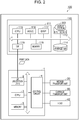
- Fig. 2 is an electrical block diagram illustrating an electrical configuration of a printing apparatus. Description follows of the electrical configuration of the printing apparatus 100, with reference to Fig. 2 .
- the printing apparatus 100 is provided with the controller 1 to control the image processing device 110 and each of the units of the printing apparatus 100.
- a personal computer or the like may be employed as the image processing device 110.
- the image processing device 110 may be provided separately to the printing apparatus 100.
- the image processing device 110 includes a printer controller 111, an input section 112, a display section 113, a storage unit 114, and the like, and controls print jobs and the like to perform printing with the printing apparatus 100.
- Software to operate the image processing device 110 includes general purpose image processing application software (referred to as an application below) to handle image data for printing, and printer driver software (referred to as a printer driver below) to generate print data to execute printing with the printing apparatus 100.
- general purpose image processing application software referred to as an application below
- printer driver software referred to as a printer driver below
- the printer controller 111 includes a central processing unit (CPU) 115, an application specific integrated circuit (ASIC) 116, a digital signal processor (DSP) 117, memory 118, an interface unit (I/F) 119, and the like, and performs centralized management of the printing apparatus 100.
- CPU central processing unit
- ASIC application specific integrated circuit
- DSP digital signal processor
- memory 118 volatile and non-volatile memory
- I/F interface unit
- the CPU 115 is a computational processing device to perform overall control the image processing device 110.
- the ASIC 116 and the DSP 117 perform image processing and the like using the printer driver under control of the CPU 115.
- the I/F 119 is provided for exchanging data between the image processing device 110 and the controller 1.
- the input section 112 is an information input unit serving as a human interface. Specifically, for example, the input section 112 is a port or the like to which a keyboard or information input device is connected.
- the display section 113 is an information display unit (display) serving as a human interface. Under control of the printer controller 111, the display section 113 displays information input through the input section 112, images to be printed by the printing apparatus 100, information related to print jobs, and the like.
- the storage unit 114 is a re-writable storage medium such as a hard disk drive (HDD), memory card, or the like.
- the storage unit 114 stores software to operate the image processing device 110 (programs to operate the printer controller 111), images to be printed, information related to print jobs, and the like.
- the memory 118 is a storage medium to secure a region for storing programs for the CPU 115 and to act as a working area for the CPU 115, and is configured by a storage element such as RAM, EEPROM, and the like.
- the controller 1 is configured including a control circuit 4, an interface (I/F) 2, a CPU 3, a memory 5, etc.
- the interface 2 performs data exchange between the image processing device 110 handing input signals and images, and the controller 1, and is a reception unit to receive print data and the like generated in the image processing device 110.
- the CPU 3 is a computational processing device to control various input signal processing and the overall printing apparatus 100.
- the memory 5 is a storage medium to secure a region for storing programs for the CPU 3 and to act as a working area for the CPU 3, and includes storage elements such as such as random access memory (RAM), Electrically Erasable Programmable Read Only Memory (EEPROM), and the like.
- RAM random access memory
- EEPROM Electrically Erasable Programmable Read Only Memory
- the controller 1 uses control signals output from the control circuit 4 to control driving of various motors installed in the medium transport unit 20 so as to move the medium 95 in the transport direction (the +X axis direction).
- the controller 1 uses control signals output from the control circuit 4 to control driving of the motor installed in the carriage transport unit 93 so as to move the carriage 43 mounted with the head 42 in the medium 95 width direction (Y axis direction).
- the controller 1 uses control signals output from the control circuit 4 to control driving of the head 42 so as to discharge liquid toward the medium 95.
- the controller 1 also controls various non-illustrated devices.
- the controller 1 controls the carriage transport unit 93 and the head 42 to perform a primary scan in which the carriage 43 (the head 42) is moved while discharging liquid, so as to form dots and a raster line along the primary scan direction.
- the controller 1 then arrays raster lines along the transport direction to form an image or the like on the medium 95 by repeatedly performing this primary scanning and secondary scanning in which the controller 1 controls the medium transport unit 20 to transport the medium 95 in the transport direction.
- Fig. 3 is a diagram to explain image processing to print an image. Next, description follows regarding print data generation processing, with reference to Fig. 3 .
- Printing on the medium 95 is started by print data being transmitted from the image processing device 110 to the controller 1.
- the print data is generated by the printer driver.
- the printer driver receives image data from an application (for example, text data, full color image data, or the like), converts the image data into print data in a format able to be interpreted by the controller 1, and outputs the print data to the controller 1.
- an application for example, text data, full color image data, or the like
- the printer driver performs resolution conversion processing, color conversion processing, halftone processing, rasterization processing, command appending processing, etc.
- the resolution conversion processing of step S1 is processing to convert image data output from an application to a resolution (print resolution) for printing on the medium 95.
- a resolution print resolution
- the print resolution is stipulated to be 720 ⁇ 720 dpi
- vector image data received from the application is converted into bitmap image data at a resolution of 720 ⁇ 720 dpi.
- Pixel data for the image data after resolution conversion processing is configured from pixels disposed in a matrix pattern. The pixels each have a gradation value in RGB color space, for example in 256 gradations. Namely, the post-resolution-conversion pixel data indicates gradation values for corresponding pixels.
- the pixel data corresponding to one row worth of pixels arrayed along a predetermined direction is called raster data.
- the predetermined direction in which the pixels corresponding to raster data are arrayed corresponds to the movement direction (primary scan direction) of the head 42 when printing images.
- the color conversion processing at step S2 is processing to convert data in RGB color space into CMYK color space.
- a color management system is employed as the system to perform such conversion.
- a color management system employs a profile (for example, an International Color Consortium (ICC) profile) listing correspondence relationships between these color spaces to perform the color space conversion.
- ICC International Color Consortium
- the color space conversion converts image data from a color space dependent on a particular machine handing the image data (the RGB color space) to a non-machine dependent color space (for example, CIELAB color space), and then converts the image data into a color space of the printing apparatus 100 on the output side (CMYK color space).
- the CMYK colors are cyan (C), magenta (M), yellow (Y), and black (B), and the image data in the CMYK color model color space is data corresponding to the inks used in the printing apparatus 100.
- the printer driver when the printing apparatus 100 employs inks of the four types of the CMYK color model, the printer driver generates image data in the four dimensional space of the CMYK color model based on the RGB data.
- This color conversion processing is performed based on a table (color conversion lookup table LUT) in which gradation values of RGB data are associated with gradation values in CMYK color model data.
- the post-color-conversion-processing pixel data is CMYK color model data expressed in CMYK color model color space, for example 256 gradations.
- the halftone processing at step S3 is processing to convert data in a high number of gradations (256 gradations) into data of a number of gradations that the controller 1 is able to form.
- the halftone processing converts the data represented in 256 gradations into 1-bit data representing two gradations (dot or no dot), or 2-bit data representing four gradations (no dot, small dot, medium dot, large dot).
- pixel data is generated from a dot generation ratio table associating gradation values (0 to 255) with dot generation ratios, and finds dot generation ratios (for example, in the case of four gradations, generation ratios for each of no dot, a small dot, a medium dot, and a large dot) corresponding to gradation values, and utilizes a dither method/error diffusion method so as to generate pixel data in which dots are formed so as to be distributed.
- dot generation ratios for example, in the case of four gradations, generation ratios for each of no dot, a small dot, a medium dot, and a large dot
- the post-halftone-processing pixel data is 1-bit or 2-bit data, and is data indicating the shape of dots (dot or no-dot, dot size) for each of the pixels in the pixel data.
- 2-bit (four gradation) data conversion is made to four gradations: a dot gradation value corresponding to no dot (00), a dot gradation value corresponding to forming a small dot (01), a dot gradation value corresponding to forming a medium dot (10), and a dot gradation value corresponding to forming a large dot (11).
- the rasterization processing at step S4 is processing to rearrange pixel data (for example, 2-bit data) arrayed in a matrix pattern according to a dot formation sequence during printing.
- the rasterization processing includes pass allocation processing to allocate the image data configured by the post-halftone-processing pixel data to each primary scan for discharging liquid while the head 42 is moved to-and-fro. When pass allocation has been completed, allocation is then made to the actual nozzles that will form each raster line configuring the image to be printed.
- the command appending processing at step S5 is processing to append command data corresponding to the type of printing to the post-rasterization-processing data.
- Examples of command data include transport data related to the manner in which the medium 95 is transported (the movement amount, speed, etc. in the transport direction).
- Print data transmission processing at step S6 is processing to transmit the generated print data to the controller 1 via the interface 119.
- step S6 The processing of the printer driver from step S1 to step S6 is performed by the ASIC 116 and the DSP 117 under control of the CPU 115 (see Fig. 2 ).
- Fig. 4 is a diagram illustrating an example of a printed image in which graininess is not visible.
- Fig. 5 is a diagram illustrating an example of a printed image in which graininess is visible.
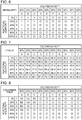
- Fig. 6 is a graininess table indicating regions where graininess is visible.
- the printing apparatus 100 of the present embodiment has printing modes including a "normal mode” in which the front face of the medium 95 is printed with colored inks, and a “bleed-through mode” in which colored inks discharged onto the front face of the medium 95 are caused by a functional liquid to penetrate through the medium toward the reverse face (bleed-through) thereof, such that the reverse face is penetration printed together with printing the front face of the medium 95 with colored inks.
- a "normal mode” in which the front face of the medium 95 is printed with colored inks
- bleed-through mode in which colored inks discharged onto the front face of the medium 95 are caused by a functional liquid to penetrate through the medium toward the reverse face (bleed-through) thereof, such that the reverse face is penetration printed together with printing the front face of the medium 95 with colored inks.
- the functional liquid includes penetrants, surfactants, and the like, and is a liquid with a function to enhance a penetration effect into the medium 95 of the colored inks discharged onto the medium 95 on which the image is formed.
- the "bleed-through mode” aims to cause the colored inks discharged onto the front face of the medium 95 to penetrate through toward the reverse face of the medium 95.
- This is a printing mode in which a functional liquid is actively employed, and "bleed-through mode" is not called such based on the printing result itself.
- the bleed-through mode is employed not only for printing to dye the front face of the medium 95, but also for printing to cause the image printed on the front face of the medium 95 to be somewhat visible on the reverse face thereof.
- the "normal mode" does not aim to make the colored inks penetrate through to the reverse face of the medium 95, and is a printing mode that would not usually use a functional liquid.
- the inventors of the present application have discovered that graininess is greatly ameliorated by discharging the functional liquid in addition to the colored inks in the bleed-through mode.
- the inventors have performed visual evaluations of the graininess of printed images formed by printing on the medium 95 using parameters of colored ink discharge amounts per unit surface area (referred to below as colored ink duty) and functional liquid discharge amounts per unit surface area (referred to below as functional liquid duty).
- the graininess table illustrated in Fig. 6 shows the results of these evaluations.
- Fig. 6 columns with colored ink duty as a parameter are labeled A to J, and rows with functional liquid duty as a parameter are labeled 1 to 6. Moreover, for example, a combination of the label "A" for a colored ink duty of 10% and a label "1" for a functional liquid duty of 0% is expressed as "discharge condition A1". In Fig. 6 , regions where graininess was visible are indicated by “x”, and regions where graininess was not visible are indicated by "O".
- the printing apparatus 100 of the present embodiment even in cases in which printing is performed in the normal mode that would not usually employ the functional liquid, functional liquid is still discharged in addition to the colored inks in regions where the colored ink discharge amount is less than a specific value (less than 40% in the present embodiment).
- the printer controller 111 references the graininess table stored in the storage unit 114, and generates functional liquid data to discharge the functional liquid.
- the functional liquid is thereby discharged in regions where the colored ink duty is less than 40%, and the graininess of printed images is ameliorated.
- the visibility of graininess in a printed image differs depending on the type of the medium 95, and so the printing apparatus 100 pre-stores plural graininess tables in the storage unit 114 corresponding to the type of the medium 95.
- Plural types of the medium 95 can be accommodated by changing the graininess table with reference to the type of the medium 95 input through the input section 112.
- the above specific value can be changed by input through the input section 112. Graininess can be ameliorated even for media which were not anticipated to be used, by a user changing the specific value based on the results of visual evaluations of images printed on the medium 95.
- the printing apparatus 100 of the present embodiment includes a normal mode and a bleed-through mode, and graininess is ameliorated in the normal mode
- the printing apparatus 100 may, in addition to the normal mode and bleed-through mode, include a separate graininess amelioration mode to execute graininess amelioration.
- the printing apparatus 100 is able to obtain the following advantageous effects.
- the printing apparatus 100 discharges functional liquid onto regions where the colored ink discharge amount in the normal mode is less than a specific value (the colored ink duty is less than 40% in the present embodiment), where graininess would be visible.
- the colored ink soaks into and wets out the surface of the medium 95 due to the functional liquid, thereby enabling graininess to be ameliorated in regions where the colored ink discharge amount is less than a specific value.
- the printing apparatus 100 includes the input section 112, and the specific value of the colored ink discharge amount, which is a threshold value to determine regions to discharge the functional liquid onto to ameliorate graininess, is changeable by input through the input section 112. This enables graininess to be ameliorated for a wide variety of media 95 that were not anticipated to be used, by a user changing the specific value based on the results of visual evaluation or the like of images printed on the medium 95.
- a printing apparatus 100 according to a second embodiment is the same as the printing apparatus of the first embodiment, and so description thereof will be omitted.
- Fig. 7 is a lightness table in a printing apparatus according to the second embodiment.
- the lightness table indicates the lightness of printed images.
- Fig. 7 indicates the lightness in CIELAB color space (referred to below as "L* value") measured, using spectroscopy, for printed images formed during printing on the image-formed medium 95 using the colored ink duty and functional liquid duty as parameters as explained with reference to Fig. 6 in the first embodiment. It is apparent from a comparison with the graininess table of Fig. 6 that for discharge conditions A1 to J1 (the row with functional liquid duty of 0%) employed to print in normal mode, graininess is visible in regions having an L* value of 60 or greater.
- the discharge condition of regions where graininess is visible is preferably changed based on the lightness (L* values). For example, when the discharge condition is A1, the L* value is 81.7.
- the discharge condition C5 in Fig. 6 which gives a region where graininess is not visible and which is similar in lightness (L* value) to the A1 value in Fig. 7 , a color can be reproduced with a brightness (lightness) substantially the same as when printed with discharge condition A1, while ameliorating graininess.
- the printing apparatus 100 of the present embodiment forms regions (referred to below as highlight areas) having a specific lightness (a L* value of 60 or greater in the present embodiment) by employing the colored inks and the functional liquid, even when printing in the normal mode that would not usually employ functional liquid.
- Fig. 8 is a conversion table to convert discharge conditions.
- the conversion table illustrated in Fig. 8 lists the converted discharge conditions resulting from converting the discharge conditions in the graininess table of Fig. 6 where graininess is visible, to discharge conditions where substantially the same color is reproduced and graininess is ameliorated.
- the discharge condition A1 resulting in a L* value of 60 or greater when printing in normal mode is converted to discharge condition C5, similarly, the discharge condition B1 is converted to discharge condition C3, and the discharge condition C1 is converted to the discharge condition D3. Functional liquid is accordingly discharged at the highlight areas even in the normal mode, and graininess is ameliorated.
- the visibility of graininess in a printed image differs depending on the type of the medium 95 on which the image is formed.
- the printing apparatus 100 accordingly pre-stores plural conversion tables in the storage unit 114 corresponding to the type of the medium 95.
- Plural types of the medium 95 can be accommodated by changing the conversion table with reference to the type of the medium 95 input through the input section 112.
- the specific lightness (L* value) referred to above can be changed by input through the input section 112. This enable a wide variety of media that were not anticipated to be used to be accommodated by a user changing the specific lightness based on the results of visual evaluation of images printed on the medium 95.
- the graininess can be suitably ameliorated due to also being able to change the functional liquid discharge amount by input through the input section 112.
- an adjustment function may be provided to enable the functional liquid discharge amount to be adjusted by input in the normal printing mode without the highlight area determination of step S102 of Fig. 9 .
- configuration may be made such that actuation of the adjustment function can be selected by a user in the normal mode, or so as to be actuated in the aforementioned graininess amelioration mode.
- an adjustment function may be provided to enable further fine adjustment of the functional liquid discharge amount after highlight area determination at step S102 and changing the discharge condition.
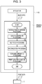
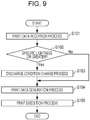
- Fig. 9 is a flowchart illustrating a printing method. Description follows regarding a printing method in which graininess is ameliorated in normal mode, with reference to Fig. 9 .
- Step S101 is a print information reception process to receive print information.
- the print information includes image data to be formed on the medium 95, and print conditions related to the type of medium, the specific lightness, the functional liquid discharge amount, and the like.
- the type of medium 95, the specific lightness (L* value), and the functional liquid discharge amount correspond to those of the respective tables of Fig. 6 to Fig. 8 .
- Step S102 is a region determination process to determine whether or not a region has a specific lightness or greater. This process is performed by the color conversion processing of step S2 in the image processing described above.
- the image processing device 110 determines whether or not the L* values of each of the pixels converted from RGB color space to CIELAB color space is 60 or greater. Processing proceeds to step S103 when the L* value is 60 or greater (Step S102: Yes), and processing proceeds to step S104 when the L* value is less than 60 (Step S102: No).
- Step S103 is a discharge condition change process to change the discharge condition. This process is performed by the halftone processing of step S3 of the image processing described above.
- the image processing device 110 references the conversion table stored in the storage unit 114.
- the image processing device 110 then changes the discharge condition for any pixels of a highlight area determined at step S102 to have an L* value of 60 or greater, from a discharge condition to discharge colored inks to a discharge condition to discharge colored ink and functional liquid. When doing so, the discharge condition is changed to a condition giving a similar lightness (L* value).
- Step S104 is a print data generation process to generate print data.
- the image processing device 110 continues the halftone processing by generating pixel data that contains pixels with L* values of less than 60.
- the image processing after the rasterization processing of above step S4 is then executed to output the generated print data to the controller 1.
- Functional liquid discharge data to discharge functional liquid for the pixels with an L* value of 60 or greater is included in the print data.
- Step S105 is a print execution process to execute printing.
- the controller 1 executes printing based on the print data by controlling each of the units of the printing apparatus 100. Discharge in the highlight areas having the specific lightness or greater is performed with discharge conditions to discharge colored ink and functional liquid, and so the colored ink soaks into and wets out the surface of the medium 95. This enables the graininess of the highlight areas to be ameliorated. Moreover, the discharge condition for the colored inks and the functional liquid is changed to a discharge condition that obtains a lightness similar to the lightness when only colored inks are discharged, thus ameliorating this graininess while also reproducing a color of substantially the same brightness (lightness).
- the printing apparatus 100 and the printing method according to the present embodiment enable the following advantageous effects to be obtained.
- the printing apparatus 100 uses the colored inks and the functional liquid to form regions having the specific lightness or greater (L* values of 60 or greater in the present embodiment) where graininess would be visible.
- the colored ink soaks into and wets out the surface of the medium 95 due to the functional liquid, enabling graininess to be ameliorated in regions of the specific lightness or greater.
- the discharge condition of the colored ink and functional liquid is changed to a discharge condition that obtains a lightness similar to the lightness when only colored inks are discharged, thus ameliorating graininess while also reproducing a color of substantially the same brightness (lightness).
- the printing apparatus 100 includes an input section 112, and the specific lightness, which is a threshold value to determine regions in which to ameliorate graininess by forming using the colored inks and the functional liquid, can be changed by input through the input section 112.
- the specific lightness which is a threshold value to determine regions in which to ameliorate graininess by forming using the colored inks and the functional liquid
- the printing method of the printing apparatus 100 includes the region determination process to determine whether or not a region is the specific lightness or greater, and the discharge condition change process to change the discharge condition in regions of the specific lightness or greater from a discharge condition to discharge only colored inks to a discharge condition to discharge colored inks and functional liquid.
- the printing method accordingly forms regions of the specific lightness or greater using the colored ink and functional liquid.
- the colored ink soaks into and wets out the surface of the medium 95 due to the functional liquid, enabling the graininess to be ameliorated in the regions of the specific lightness or greater.
- the discharge condition of colored ink and functional liquid is changed to a discharge condition that obtains substantially the same lightness to that when only colored inks are discharged, and so the graininess thereof can be ameliorated while reproducing a color of substantially the same brightness (lightness).
Landscapes
- Ink Jet (AREA)
- Ink Jet Recording Methods And Recording Media Thereof (AREA)
- Coloring (AREA)
- Accessory Devices And Overall Control Thereof (AREA)
Applications Claiming Priority (1)
| Application Number | Priority Date | Filing Date | Title |
|---|---|---|---|
| JP2017018243A JP6760118B2 (ja) | 2017-02-03 | 2017-02-03 | 印刷装置及び印刷方法 |
Publications (2)
| Publication Number | Publication Date |
|---|---|
| EP3357699A1 true EP3357699A1 (fr) | 2018-08-08 |
| EP3357699B1 EP3357699B1 (fr) | 2021-05-26 |
Family
ID=61157138
Family Applications (1)
| Application Number | Title | Priority Date | Filing Date |
|---|---|---|---|
| EP18155005.4A Active EP3357699B1 (fr) | 2017-02-03 | 2018-02-02 | Imprimante et procédé d'impression |
Country Status (3)
| Country | Link |
|---|---|
| EP (1) | EP3357699B1 (fr) |
| JP (1) | JP6760118B2 (fr) |
| CN (1) | CN108382076B (fr) |
Cited By (2)
| Publication number | Priority date | Publication date | Assignee | Title |
|---|---|---|---|---|
| US11020983B2 (en) | 2019-01-16 | 2021-06-01 | Seiko Epson Corporation | Liquid ejecting device and liquid ejecting method |
| WO2022024109A1 (fr) | 2020-07-29 | 2022-02-03 | Kornit Digital Ltd. | Procédé d'impression à jet d'encre |
Families Citing this family (1)
| Publication number | Priority date | Publication date | Assignee | Title |
|---|---|---|---|---|
| JP7439595B2 (ja) | 2020-03-18 | 2024-02-28 | セイコーエプソン株式会社 | 記録装置および記録方法 |
Citations (4)
| Publication number | Priority date | Publication date | Assignee | Title |
|---|---|---|---|---|
| US6454402B1 (en) * | 1998-12-24 | 2002-09-24 | Canon Kabushiki Kaisha | Ink-jet printing method an ink-jet printing apparatus |
| US20060071990A1 (en) * | 2004-09-24 | 2006-04-06 | Fuji Photo Film Co., Ltd. | Image forming apparatus and method |
| JP2009017133A (ja) | 2007-07-03 | 2009-01-22 | Canon Inc | 画像処理方法、及び記録装置 |
| WO2013008244A1 (fr) * | 2011-07-14 | 2013-01-17 | Maheshwari, Sanjay Chandermohan | Procédé et appareil pour l'impression numérique sur textiles |
Family Cites Families (11)
| Publication number | Priority date | Publication date | Assignee | Title |
|---|---|---|---|---|
| JP3177113B2 (ja) * | 1995-02-13 | 2001-06-18 | キヤノン株式会社 | インクジェット記録装置、インクジェット記録方法およびデータ作成方法 |
| JP4227267B2 (ja) * | 1998-12-24 | 2009-02-18 | キヤノン株式会社 | インクジェットプリント方法およびインクジェットプリント装置 |
| JP3997019B2 (ja) * | 1998-12-25 | 2007-10-24 | キヤノン株式会社 | プリント方法およびプリント装置 |
| JP4099727B2 (ja) * | 2006-08-11 | 2008-06-11 | 大日本インキ化学工業株式会社 | 布帛用インクジェットインク受理性付与剤及びそれを用いて加工された布帛 |
| JP5713992B2 (ja) * | 2009-09-14 | 2015-05-07 | 富士フイルム株式会社 | インクジェット印字方法および装置 |
| JP2011121335A (ja) * | 2009-12-14 | 2011-06-23 | Canon Inc | インクジェット記録システム及び記録方法 |
| US8485657B2 (en) * | 2010-01-08 | 2013-07-16 | Advanced Chemical Solutions, Llc | Sublimation printing processes and fabric pretreatment compositions for ink jet printing onto arbitrary fabrics |
| JP5569035B2 (ja) * | 2010-02-26 | 2014-08-13 | セイコーエプソン株式会社 | インクジェット捺染方法 |
| JP5857469B2 (ja) * | 2011-06-23 | 2016-02-10 | セイコーエプソン株式会社 | インクジェット捺染方法、インクジェット捺染装置 |
| JP6037096B2 (ja) * | 2011-11-07 | 2016-11-30 | セイコーエプソン株式会社 | インクジェット捺染装置及び印捺物の製造方法 |
| EP3023464B1 (fr) * | 2014-11-19 | 2020-07-22 | Konica Minolta, Inc. | Encre aqueuse pour impression à jet d'encre, jeu d'encre et procédé d'impression à jet d'encre |
-
2017
- 2017-02-03 JP JP2017018243A patent/JP6760118B2/ja active Active
-
2018
- 2018-01-22 CN CN201810058700.4A patent/CN108382076B/zh active Active
- 2018-02-02 EP EP18155005.4A patent/EP3357699B1/fr active Active
Patent Citations (4)
| Publication number | Priority date | Publication date | Assignee | Title |
|---|---|---|---|---|
| US6454402B1 (en) * | 1998-12-24 | 2002-09-24 | Canon Kabushiki Kaisha | Ink-jet printing method an ink-jet printing apparatus |
| US20060071990A1 (en) * | 2004-09-24 | 2006-04-06 | Fuji Photo Film Co., Ltd. | Image forming apparatus and method |
| JP2009017133A (ja) | 2007-07-03 | 2009-01-22 | Canon Inc | 画像処理方法、及び記録装置 |
| WO2013008244A1 (fr) * | 2011-07-14 | 2013-01-17 | Maheshwari, Sanjay Chandermohan | Procédé et appareil pour l'impression numérique sur textiles |
Cited By (3)
| Publication number | Priority date | Publication date | Assignee | Title |
|---|---|---|---|---|
| US11020983B2 (en) | 2019-01-16 | 2021-06-01 | Seiko Epson Corporation | Liquid ejecting device and liquid ejecting method |
| WO2022024109A1 (fr) | 2020-07-29 | 2022-02-03 | Kornit Digital Ltd. | Procédé d'impression à jet d'encre |
| EP4189598A4 (fr) * | 2020-07-29 | 2024-08-07 | Kornit Digital Ltd. | Procédé d'impression à jet d'encre |
Also Published As
| Publication number | Publication date |
|---|---|
| JP6760118B2 (ja) | 2020-09-23 |
| EP3357699B1 (fr) | 2021-05-26 |
| CN108382076A (zh) | 2018-08-10 |
| JP2018122557A (ja) | 2018-08-09 |
| CN108382076B (zh) | 2021-05-04 |
Similar Documents
| Publication | Publication Date | Title |
|---|---|---|
| US10708468B2 (en) | Image processing method, image processing device and printing system utilizing different gradation tables in overlapping regions based on attribute and environmental information | |
| GB2274755A (en) | Image Processing Apparatus | |
| EP3357699B1 (fr) | Imprimante et procédé d'impression | |
| US8899707B2 (en) | Printing apparatus | |
| US11845269B2 (en) | Printing apparatus and printing method | |
| CN109016866A (zh) | 图像处理装置以及印刷系统 | |
| JP6836134B2 (ja) | 印刷装置および印刷装置の調整方法 | |
| US9061498B2 (en) | Printing device, and method for performing wiping operation | |
| EP3235648B1 (fr) | Imprimante et procédé d'impression | |
| JP2021133601A (ja) | 印刷方法および印刷装置 | |
| JP6815511B2 (ja) | 画像処理装置及び方法、プログラム並びに画像記録装置 | |
| JP2018134744A (ja) | 画像処理装置及び印刷装置 | |
| JP2021138051A (ja) | 印刷装置および測色方法 | |
| CN108116054B (zh) | 图像处理装置、印刷装置及系统、液体更换数据生成方法 | |
| JP7740962B2 (ja) | 色調整装置及び方法、情報処理装置、プログラム、印刷システム並びに印刷物の製造方法 | |
| JP7354725B2 (ja) | 画像形成装置、画像形成制御プログラム、及び情報処理プログラム | |
| JP6094072B2 (ja) | 印刷装置及び印刷方法 | |
| US8814325B2 (en) | Printing device and print head | |
| US11507790B2 (en) | Printing method in which each of raster lines configuring line image is formed by plurality of pass operations, printing device that forms each of raster lines configuring line image by plurality of pass operations, and printing system | |
| JP7476496B2 (ja) | 記録条件の決定方法および記録装置 | |
| US20210402797A1 (en) | Printing apparatus and printing method | |
| JP2019147331A (ja) | 画像処理装置及び画像処理方法 | |
| JP2023064868A (ja) | 画像処理装置、画像処理システム、及び画像処理方法 | |
| JP2018122555A (ja) | 液体吐出装置及び液体吐出方法 |
Legal Events
| Date | Code | Title | Description |
|---|---|---|---|
| PUAI | Public reference made under article 153(3) epc to a published international application that has entered the european phase |
Free format text: ORIGINAL CODE: 0009012 |
|
| STAA | Information on the status of an ep patent application or granted ep patent |
Free format text: STATUS: THE APPLICATION HAS BEEN PUBLISHED |
|
| AK | Designated contracting states |
Kind code of ref document: A1 Designated state(s): AL AT BE BG CH CY CZ DE DK EE ES FI FR GB GR HR HU IE IS IT LI LT LU LV MC MK MT NL NO PL PT RO RS SE SI SK SM TR |
|
| AX | Request for extension of the european patent |
Extension state: BA ME |
|
| STAA | Information on the status of an ep patent application or granted ep patent |
Free format text: STATUS: REQUEST FOR EXAMINATION WAS MADE |
|
| 17P | Request for examination filed |
Effective date: 20190208 |
|
| RBV | Designated contracting states (corrected) |
Designated state(s): AL AT BE BG CH CY CZ DE DK EE ES FI FR GB GR HR HU IE IS IT LI LT LU LV MC MK MT NL NO PL PT RO RS SE SI SK SM TR |
|
| REG | Reference to a national code |
Ref country code: DE Ref legal event code: R079 Ref document number: 602018017491 Country of ref document: DE Free format text: PREVIOUS MAIN CLASS: B41J0002210000 Ipc: B41J0011000000 |
|
| GRAP | Despatch of communication of intention to grant a patent |
Free format text: ORIGINAL CODE: EPIDOSNIGR1 |
|
| STAA | Information on the status of an ep patent application or granted ep patent |
Free format text: STATUS: GRANT OF PATENT IS INTENDED |
|
| RIC1 | Information provided on ipc code assigned before grant |
Ipc: B41J 3/407 20060101ALI20201124BHEP Ipc: B41J 2/21 20060101ALI20201124BHEP Ipc: B41J 11/00 20060101AFI20201124BHEP |
|
| INTG | Intention to grant announced |
Effective date: 20201217 |
|
| GRAS | Grant fee paid |
Free format text: ORIGINAL CODE: EPIDOSNIGR3 |
|
| GRAA | (expected) grant |
Free format text: ORIGINAL CODE: 0009210 |
|
| STAA | Information on the status of an ep patent application or granted ep patent |
Free format text: STATUS: THE PATENT HAS BEEN GRANTED |
|
| AK | Designated contracting states |
Kind code of ref document: B1 Designated state(s): AL AT BE BG CH CY CZ DE DK EE ES FI FR GB GR HR HU IE IS IT LI LT LU LV MC MK MT NL NO PL PT RO RS SE SI SK SM TR |
|
| REG | Reference to a national code |
Ref country code: GB Ref legal event code: FG4D |
|
| REG | Reference to a national code |
Ref country code: CH Ref legal event code: EP |
|
| REG | Reference to a national code |
Ref country code: AT Ref legal event code: REF Ref document number: 1395825 Country of ref document: AT Kind code of ref document: T Effective date: 20210615 |
|
| REG | Reference to a national code |
Ref country code: DE Ref legal event code: R096 Ref document number: 602018017491 Country of ref document: DE |
|
| REG | Reference to a national code |
Ref country code: IE Ref legal event code: FG4D |
|
| REG | Reference to a national code |
Ref country code: LT Ref legal event code: MG9D |
|
| REG | Reference to a national code |
Ref country code: AT Ref legal event code: MK05 Ref document number: 1395825 Country of ref document: AT Kind code of ref document: T Effective date: 20210526 |
|
| PG25 | Lapsed in a contracting state [announced via postgrant information from national office to epo] |
Ref country code: FI Free format text: LAPSE BECAUSE OF FAILURE TO SUBMIT A TRANSLATION OF THE DESCRIPTION OR TO PAY THE FEE WITHIN THE PRESCRIBED TIME-LIMIT Effective date: 20210526 Ref country code: LT Free format text: LAPSE BECAUSE OF FAILURE TO SUBMIT A TRANSLATION OF THE DESCRIPTION OR TO PAY THE FEE WITHIN THE PRESCRIBED TIME-LIMIT Effective date: 20210526 Ref country code: HR Free format text: LAPSE BECAUSE OF FAILURE TO SUBMIT A TRANSLATION OF THE DESCRIPTION OR TO PAY THE FEE WITHIN THE PRESCRIBED TIME-LIMIT Effective date: 20210526 Ref country code: AT Free format text: LAPSE BECAUSE OF FAILURE TO SUBMIT A TRANSLATION OF THE DESCRIPTION OR TO PAY THE FEE WITHIN THE PRESCRIBED TIME-LIMIT Effective date: 20210526 Ref country code: BG Free format text: LAPSE BECAUSE OF FAILURE TO SUBMIT A TRANSLATION OF THE DESCRIPTION OR TO PAY THE FEE WITHIN THE PRESCRIBED TIME-LIMIT Effective date: 20210826 |
|
| REG | Reference to a national code |
Ref country code: NL Ref legal event code: MP Effective date: 20210526 |
|
| PG25 | Lapsed in a contracting state [announced via postgrant information from national office to epo] |
Ref country code: IS Free format text: LAPSE BECAUSE OF FAILURE TO SUBMIT A TRANSLATION OF THE DESCRIPTION OR TO PAY THE FEE WITHIN THE PRESCRIBED TIME-LIMIT Effective date: 20210926 Ref country code: GR Free format text: LAPSE BECAUSE OF FAILURE TO SUBMIT A TRANSLATION OF THE DESCRIPTION OR TO PAY THE FEE WITHIN THE PRESCRIBED TIME-LIMIT Effective date: 20210827 Ref country code: PT Free format text: LAPSE BECAUSE OF FAILURE TO SUBMIT A TRANSLATION OF THE DESCRIPTION OR TO PAY THE FEE WITHIN THE PRESCRIBED TIME-LIMIT Effective date: 20210927 Ref country code: PL Free format text: LAPSE BECAUSE OF FAILURE TO SUBMIT A TRANSLATION OF THE DESCRIPTION OR TO PAY THE FEE WITHIN THE PRESCRIBED TIME-LIMIT Effective date: 20210526 Ref country code: NO Free format text: LAPSE BECAUSE OF FAILURE TO SUBMIT A TRANSLATION OF THE DESCRIPTION OR TO PAY THE FEE WITHIN THE PRESCRIBED TIME-LIMIT Effective date: 20210826 Ref country code: LV Free format text: LAPSE BECAUSE OF FAILURE TO SUBMIT A TRANSLATION OF THE DESCRIPTION OR TO PAY THE FEE WITHIN THE PRESCRIBED TIME-LIMIT Effective date: 20210526 Ref country code: RS Free format text: LAPSE BECAUSE OF FAILURE TO SUBMIT A TRANSLATION OF THE DESCRIPTION OR TO PAY THE FEE WITHIN THE PRESCRIBED TIME-LIMIT Effective date: 20210526 Ref country code: SE Free format text: LAPSE BECAUSE OF FAILURE TO SUBMIT A TRANSLATION OF THE DESCRIPTION OR TO PAY THE FEE WITHIN THE PRESCRIBED TIME-LIMIT Effective date: 20210526 |
|
| PG25 | Lapsed in a contracting state [announced via postgrant information from national office to epo] |
Ref country code: NL Free format text: LAPSE BECAUSE OF FAILURE TO SUBMIT A TRANSLATION OF THE DESCRIPTION OR TO PAY THE FEE WITHIN THE PRESCRIBED TIME-LIMIT Effective date: 20210526 |
|
| PG25 | Lapsed in a contracting state [announced via postgrant information from national office to epo] |
Ref country code: SK Free format text: LAPSE BECAUSE OF FAILURE TO SUBMIT A TRANSLATION OF THE DESCRIPTION OR TO PAY THE FEE WITHIN THE PRESCRIBED TIME-LIMIT Effective date: 20210526 Ref country code: SM Free format text: LAPSE BECAUSE OF FAILURE TO SUBMIT A TRANSLATION OF THE DESCRIPTION OR TO PAY THE FEE WITHIN THE PRESCRIBED TIME-LIMIT Effective date: 20210526 Ref country code: ES Free format text: LAPSE BECAUSE OF FAILURE TO SUBMIT A TRANSLATION OF THE DESCRIPTION OR TO PAY THE FEE WITHIN THE PRESCRIBED TIME-LIMIT Effective date: 20210526 Ref country code: EE Free format text: LAPSE BECAUSE OF FAILURE TO SUBMIT A TRANSLATION OF THE DESCRIPTION OR TO PAY THE FEE WITHIN THE PRESCRIBED TIME-LIMIT Effective date: 20210526 Ref country code: RO Free format text: LAPSE BECAUSE OF FAILURE TO SUBMIT A TRANSLATION OF THE DESCRIPTION OR TO PAY THE FEE WITHIN THE PRESCRIBED TIME-LIMIT Effective date: 20210526 Ref country code: DK Free format text: LAPSE BECAUSE OF FAILURE TO SUBMIT A TRANSLATION OF THE DESCRIPTION OR TO PAY THE FEE WITHIN THE PRESCRIBED TIME-LIMIT Effective date: 20210526 Ref country code: CZ Free format text: LAPSE BECAUSE OF FAILURE TO SUBMIT A TRANSLATION OF THE DESCRIPTION OR TO PAY THE FEE WITHIN THE PRESCRIBED TIME-LIMIT Effective date: 20210526 |
|
| REG | Reference to a national code |
Ref country code: DE Ref legal event code: R097 Ref document number: 602018017491 Country of ref document: DE |
|
| PLBE | No opposition filed within time limit |
Free format text: ORIGINAL CODE: 0009261 |
|
| STAA | Information on the status of an ep patent application or granted ep patent |
Free format text: STATUS: NO OPPOSITION FILED WITHIN TIME LIMIT |
|
| 26N | No opposition filed |
Effective date: 20220301 |
|
| PG25 | Lapsed in a contracting state [announced via postgrant information from national office to epo] |
Ref country code: IS Free format text: LAPSE BECAUSE OF FAILURE TO SUBMIT A TRANSLATION OF THE DESCRIPTION OR TO PAY THE FEE WITHIN THE PRESCRIBED TIME-LIMIT Effective date: 20210926 Ref country code: AL Free format text: LAPSE BECAUSE OF FAILURE TO SUBMIT A TRANSLATION OF THE DESCRIPTION OR TO PAY THE FEE WITHIN THE PRESCRIBED TIME-LIMIT Effective date: 20210526 |
|
| PG25 | Lapsed in a contracting state [announced via postgrant information from national office to epo] |
Ref country code: MC Free format text: LAPSE BECAUSE OF FAILURE TO SUBMIT A TRANSLATION OF THE DESCRIPTION OR TO PAY THE FEE WITHIN THE PRESCRIBED TIME-LIMIT Effective date: 20210526 |
|
| REG | Reference to a national code |
Ref country code: CH Ref legal event code: PL |
|
| REG | Reference to a national code |
Ref country code: BE Ref legal event code: MM Effective date: 20220228 |
|
| GBPC | Gb: european patent ceased through non-payment of renewal fee |
Effective date: 20220202 |
|
| PG25 | Lapsed in a contracting state [announced via postgrant information from national office to epo] |
Ref country code: LU Free format text: LAPSE BECAUSE OF NON-PAYMENT OF DUE FEES Effective date: 20220202 |
|
| PG25 | Lapsed in a contracting state [announced via postgrant information from national office to epo] |
Ref country code: LI Free format text: LAPSE BECAUSE OF NON-PAYMENT OF DUE FEES Effective date: 20220228 Ref country code: IE Free format text: LAPSE BECAUSE OF NON-PAYMENT OF DUE FEES Effective date: 20220202 Ref country code: GB Free format text: LAPSE BECAUSE OF NON-PAYMENT OF DUE FEES Effective date: 20220202 Ref country code: CH Free format text: LAPSE BECAUSE OF NON-PAYMENT OF DUE FEES Effective date: 20220228 |
|
| PG25 | Lapsed in a contracting state [announced via postgrant information from national office to epo] |
Ref country code: BE Free format text: LAPSE BECAUSE OF NON-PAYMENT OF DUE FEES Effective date: 20220228 |
|
| PG25 | Lapsed in a contracting state [announced via postgrant information from national office to epo] |
Ref country code: HU Free format text: LAPSE BECAUSE OF FAILURE TO SUBMIT A TRANSLATION OF THE DESCRIPTION OR TO PAY THE FEE WITHIN THE PRESCRIBED TIME-LIMIT; INVALID AB INITIO Effective date: 20180202 |
|
| PG25 | Lapsed in a contracting state [announced via postgrant information from national office to epo] |
Ref country code: MK Free format text: LAPSE BECAUSE OF FAILURE TO SUBMIT A TRANSLATION OF THE DESCRIPTION OR TO PAY THE FEE WITHIN THE PRESCRIBED TIME-LIMIT Effective date: 20210526 Ref country code: CY Free format text: LAPSE BECAUSE OF FAILURE TO SUBMIT A TRANSLATION OF THE DESCRIPTION OR TO PAY THE FEE WITHIN THE PRESCRIBED TIME-LIMIT Effective date: 20210526 |
|
| PG25 | Lapsed in a contracting state [announced via postgrant information from national office to epo] |
Ref country code: MT Free format text: LAPSE BECAUSE OF FAILURE TO SUBMIT A TRANSLATION OF THE DESCRIPTION OR TO PAY THE FEE WITHIN THE PRESCRIBED TIME-LIMIT Effective date: 20210526 |
|
| PGFP | Annual fee paid to national office [announced via postgrant information from national office to epo] |
Ref country code: FR Payment date: 20241231 Year of fee payment: 8 |
|
| PGFP | Annual fee paid to national office [announced via postgrant information from national office to epo] |
Ref country code: DE Payment date: 20241231 Year of fee payment: 8 |
|
| PG25 | Lapsed in a contracting state [announced via postgrant information from national office to epo] |
Ref country code: TR Free format text: LAPSE BECAUSE OF FAILURE TO SUBMIT A TRANSLATION OF THE DESCRIPTION OR TO PAY THE FEE WITHIN THE PRESCRIBED TIME-LIMIT Effective date: 20210526 |
|
| PGFP | Annual fee paid to national office [announced via postgrant information from national office to epo] |
Ref country code: IT Payment date: 20260122 Year of fee payment: 9 |