EP3357775B1 - Appareil de commande de véhicule - Google Patents
Appareil de commande de véhicule Download PDFInfo
- Publication number
- EP3357775B1 EP3357775B1 EP18152389.5A EP18152389A EP3357775B1 EP 3357775 B1 EP3357775 B1 EP 3357775B1 EP 18152389 A EP18152389 A EP 18152389A EP 3357775 B1 EP3357775 B1 EP 3357775B1
- Authority
- EP
- European Patent Office
- Prior art keywords
- control
- vehicle
- fuel
- acceleration
- area
- Prior art date
- Legal status (The legal status is an assumption and is not a legal conclusion. Google has not performed a legal analysis and makes no representation as to the accuracy of the status listed.)
- Not-in-force
Links
Images


Classifications
-
- B—PERFORMING OPERATIONS; TRANSPORTING
- B60—VEHICLES IN GENERAL
- B60W—CONJOINT CONTROL OF VEHICLE SUB-UNITS OF DIFFERENT TYPE OR DIFFERENT FUNCTION; CONTROL SYSTEMS SPECIALLY ADAPTED FOR HYBRID VEHICLES; ROAD VEHICLE DRIVE CONTROL SYSTEMS FOR PURPOSES NOT RELATED TO THE CONTROL OF A PARTICULAR SUB-UNIT
- B60W30/00—Purposes of road vehicle drive control systems not related to the control of a particular sub-unit, e.g. of systems using conjoint control of vehicle sub-units
- B60W30/18—Propelling the vehicle
- B60W30/188—Controlling power parameters of the driveline, e.g. determining the required power
-
- B—PERFORMING OPERATIONS; TRANSPORTING
- B60—VEHICLES IN GENERAL
- B60W—CONJOINT CONTROL OF VEHICLE SUB-UNITS OF DIFFERENT TYPE OR DIFFERENT FUNCTION; CONTROL SYSTEMS SPECIALLY ADAPTED FOR HYBRID VEHICLES; ROAD VEHICLE DRIVE CONTROL SYSTEMS FOR PURPOSES NOT RELATED TO THE CONTROL OF A PARTICULAR SUB-UNIT
- B60W10/00—Conjoint control of vehicle sub-units of different type or different function
- B60W10/04—Conjoint control of vehicle sub-units of different type or different function including control of propulsion units
- B60W10/06—Conjoint control of vehicle sub-units of different type or different function including control of propulsion units including control of combustion engines
-
- B—PERFORMING OPERATIONS; TRANSPORTING
- B60—VEHICLES IN GENERAL
- B60W—CONJOINT CONTROL OF VEHICLE SUB-UNITS OF DIFFERENT TYPE OR DIFFERENT FUNCTION; CONTROL SYSTEMS SPECIALLY ADAPTED FOR HYBRID VEHICLES; ROAD VEHICLE DRIVE CONTROL SYSTEMS FOR PURPOSES NOT RELATED TO THE CONTROL OF A PARTICULAR SUB-UNIT
- B60W30/00—Purposes of road vehicle drive control systems not related to the control of a particular sub-unit, e.g. of systems using conjoint control of vehicle sub-units
- B60W30/18—Propelling the vehicle
- B60W30/18009—Propelling the vehicle related to particular drive situations
- B60W30/18018—Start-stop drive, e.g. in a traffic jam
-
- B—PERFORMING OPERATIONS; TRANSPORTING
- B60—VEHICLES IN GENERAL
- B60W—CONJOINT CONTROL OF VEHICLE SUB-UNITS OF DIFFERENT TYPE OR DIFFERENT FUNCTION; CONTROL SYSTEMS SPECIALLY ADAPTED FOR HYBRID VEHICLES; ROAD VEHICLE DRIVE CONTROL SYSTEMS FOR PURPOSES NOT RELATED TO THE CONTROL OF A PARTICULAR SUB-UNIT
- B60W30/00—Purposes of road vehicle drive control systems not related to the control of a particular sub-unit, e.g. of systems using conjoint control of vehicle sub-units
- B60W30/18—Propelling the vehicle
- B60W30/18009—Propelling the vehicle related to particular drive situations
- B60W30/18072—Coasting
-
- B—PERFORMING OPERATIONS; TRANSPORTING
- B60—VEHICLES IN GENERAL
- B60W—CONJOINT CONTROL OF VEHICLE SUB-UNITS OF DIFFERENT TYPE OR DIFFERENT FUNCTION; CONTROL SYSTEMS SPECIALLY ADAPTED FOR HYBRID VEHICLES; ROAD VEHICLE DRIVE CONTROL SYSTEMS FOR PURPOSES NOT RELATED TO THE CONTROL OF A PARTICULAR SUB-UNIT
- B60W30/00—Purposes of road vehicle drive control systems not related to the control of a particular sub-unit, e.g. of systems using conjoint control of vehicle sub-units
- B60W30/18—Propelling the vehicle
- B60W30/182—Selecting between different operative modes, e.g. comfort and performance modes
-
- B—PERFORMING OPERATIONS; TRANSPORTING
- B60—VEHICLES IN GENERAL
- B60W—CONJOINT CONTROL OF VEHICLE SUB-UNITS OF DIFFERENT TYPE OR DIFFERENT FUNCTION; CONTROL SYSTEMS SPECIALLY ADAPTED FOR HYBRID VEHICLES; ROAD VEHICLE DRIVE CONTROL SYSTEMS FOR PURPOSES NOT RELATED TO THE CONTROL OF A PARTICULAR SUB-UNIT
- B60W40/00—Estimation or calculation of non-directly measurable driving parameters for road vehicle drive control systems not related to the control of a particular sub unit, e.g. by using mathematical models
- B60W40/08—Estimation or calculation of non-directly measurable driving parameters for road vehicle drive control systems not related to the control of a particular sub unit, e.g. by using mathematical models related to drivers or passengers
-
- G—PHYSICS
- G08—SIGNALLING
- G08G—TRAFFIC CONTROL SYSTEMS
- G08G1/00—Traffic control systems for road vehicles
- G08G1/01—Detecting movement of traffic to be counted or controlled
- G08G1/0104—Measuring and analyzing of parameters relative to traffic conditions
- G08G1/0108—Measuring and analyzing of parameters relative to traffic conditions based on the source of data
- G08G1/0112—Measuring and analyzing of parameters relative to traffic conditions based on the source of data from the vehicle, e.g. floating car data [FCD]
-
- G—PHYSICS
- G08—SIGNALLING
- G08G—TRAFFIC CONTROL SYSTEMS
- G08G1/00—Traffic control systems for road vehicles
- G08G1/09—Arrangements for giving variable traffic instructions
- G08G1/0962—Arrangements for giving variable traffic instructions having an indicator mounted inside the vehicle, e.g. giving voice messages
- G08G1/0967—Systems involving transmission of highway information, e.g. weather, speed limits
- G08G1/096708—Systems involving transmission of highway information, e.g. weather, speed limits where the received information might be used to generate an automatic action on the vehicle control
- G08G1/096725—Systems involving transmission of highway information, e.g. weather, speed limits where the received information might be used to generate an automatic action on the vehicle control where the received information generates an automatic action on the vehicle control
-
- B—PERFORMING OPERATIONS; TRANSPORTING
- B60—VEHICLES IN GENERAL
- B60W—CONJOINT CONTROL OF VEHICLE SUB-UNITS OF DIFFERENT TYPE OR DIFFERENT FUNCTION; CONTROL SYSTEMS SPECIALLY ADAPTED FOR HYBRID VEHICLES; ROAD VEHICLE DRIVE CONTROL SYSTEMS FOR PURPOSES NOT RELATED TO THE CONTROL OF A PARTICULAR SUB-UNIT
- B60W30/00—Purposes of road vehicle drive control systems not related to the control of a particular sub-unit, e.g. of systems using conjoint control of vehicle sub-units
- B60W30/18—Propelling the vehicle
- B60W30/18009—Propelling the vehicle related to particular drive situations
- B60W30/18072—Coasting
- B60W2030/1809—Without torque flow between driveshaft and engine, e.g. with clutch disengaged or transmission in neutral
-
- B—PERFORMING OPERATIONS; TRANSPORTING
- B60—VEHICLES IN GENERAL
- B60W—CONJOINT CONTROL OF VEHICLE SUB-UNITS OF DIFFERENT TYPE OR DIFFERENT FUNCTION; CONTROL SYSTEMS SPECIALLY ADAPTED FOR HYBRID VEHICLES; ROAD VEHICLE DRIVE CONTROL SYSTEMS FOR PURPOSES NOT RELATED TO THE CONTROL OF A PARTICULAR SUB-UNIT
- B60W50/00—Details of control systems for road vehicle drive control not related to the control of a particular sub-unit, e.g. process diagnostic or vehicle driver interfaces
- B60W2050/0062—Adapting control system settings
- B60W2050/007—Switching between manual and automatic parameter input, and vice versa
- B60W2050/0073—Driver overrides controller
-
- B—PERFORMING OPERATIONS; TRANSPORTING
- B60—VEHICLES IN GENERAL
- B60W—CONJOINT CONTROL OF VEHICLE SUB-UNITS OF DIFFERENT TYPE OR DIFFERENT FUNCTION; CONTROL SYSTEMS SPECIALLY ADAPTED FOR HYBRID VEHICLES; ROAD VEHICLE DRIVE CONTROL SYSTEMS FOR PURPOSES NOT RELATED TO THE CONTROL OF A PARTICULAR SUB-UNIT
- B60W2510/00—Input parameters relating to a particular sub-units
- B60W2510/06—Combustion engines, Gas turbines
- B60W2510/0604—Throttle position
-
- B—PERFORMING OPERATIONS; TRANSPORTING
- B60—VEHICLES IN GENERAL
- B60W—CONJOINT CONTROL OF VEHICLE SUB-UNITS OF DIFFERENT TYPE OR DIFFERENT FUNCTION; CONTROL SYSTEMS SPECIALLY ADAPTED FOR HYBRID VEHICLES; ROAD VEHICLE DRIVE CONTROL SYSTEMS FOR PURPOSES NOT RELATED TO THE CONTROL OF A PARTICULAR SUB-UNIT
- B60W2510/00—Input parameters relating to a particular sub-units
- B60W2510/06—Combustion engines, Gas turbines
- B60W2510/0604—Throttle position
- B60W2510/0609—Throttle change rate
-
- B—PERFORMING OPERATIONS; TRANSPORTING
- B60—VEHICLES IN GENERAL
- B60W—CONJOINT CONTROL OF VEHICLE SUB-UNITS OF DIFFERENT TYPE OR DIFFERENT FUNCTION; CONTROL SYSTEMS SPECIALLY ADAPTED FOR HYBRID VEHICLES; ROAD VEHICLE DRIVE CONTROL SYSTEMS FOR PURPOSES NOT RELATED TO THE CONTROL OF A PARTICULAR SUB-UNIT
- B60W2520/00—Input parameters relating to overall vehicle dynamics
- B60W2520/10—Longitudinal speed
-
- B—PERFORMING OPERATIONS; TRANSPORTING
- B60—VEHICLES IN GENERAL
- B60W—CONJOINT CONTROL OF VEHICLE SUB-UNITS OF DIFFERENT TYPE OR DIFFERENT FUNCTION; CONTROL SYSTEMS SPECIALLY ADAPTED FOR HYBRID VEHICLES; ROAD VEHICLE DRIVE CONTROL SYSTEMS FOR PURPOSES NOT RELATED TO THE CONTROL OF A PARTICULAR SUB-UNIT
- B60W2540/00—Input parameters relating to occupants
- B60W2540/215—Selection or confirmation of options
-
- B—PERFORMING OPERATIONS; TRANSPORTING
- B60—VEHICLES IN GENERAL
- B60W—CONJOINT CONTROL OF VEHICLE SUB-UNITS OF DIFFERENT TYPE OR DIFFERENT FUNCTION; CONTROL SYSTEMS SPECIALLY ADAPTED FOR HYBRID VEHICLES; ROAD VEHICLE DRIVE CONTROL SYSTEMS FOR PURPOSES NOT RELATED TO THE CONTROL OF A PARTICULAR SUB-UNIT
- B60W2552/00—Input parameters relating to infrastructure
- B60W2552/05—Type of road, e.g. motorways, local streets, paved or unpaved roads
-
- B—PERFORMING OPERATIONS; TRANSPORTING
- B60—VEHICLES IN GENERAL
- B60W—CONJOINT CONTROL OF VEHICLE SUB-UNITS OF DIFFERENT TYPE OR DIFFERENT FUNCTION; CONTROL SYSTEMS SPECIALLY ADAPTED FOR HYBRID VEHICLES; ROAD VEHICLE DRIVE CONTROL SYSTEMS FOR PURPOSES NOT RELATED TO THE CONTROL OF A PARTICULAR SUB-UNIT
- B60W2552/00—Input parameters relating to infrastructure
- B60W2552/15—Road slope, i.e. the inclination of a road segment in the longitudinal direction
-
- B—PERFORMING OPERATIONS; TRANSPORTING
- B60—VEHICLES IN GENERAL
- B60W—CONJOINT CONTROL OF VEHICLE SUB-UNITS OF DIFFERENT TYPE OR DIFFERENT FUNCTION; CONTROL SYSTEMS SPECIALLY ADAPTED FOR HYBRID VEHICLES; ROAD VEHICLE DRIVE CONTROL SYSTEMS FOR PURPOSES NOT RELATED TO THE CONTROL OF A PARTICULAR SUB-UNIT
- B60W2556/00—Input parameters relating to data
- B60W2556/45—External transmission of data to or from the vehicle
-
- B—PERFORMING OPERATIONS; TRANSPORTING
- B60—VEHICLES IN GENERAL
- B60W—CONJOINT CONTROL OF VEHICLE SUB-UNITS OF DIFFERENT TYPE OR DIFFERENT FUNCTION; CONTROL SYSTEMS SPECIALLY ADAPTED FOR HYBRID VEHICLES; ROAD VEHICLE DRIVE CONTROL SYSTEMS FOR PURPOSES NOT RELATED TO THE CONTROL OF A PARTICULAR SUB-UNIT
- B60W2556/00—Input parameters relating to data
- B60W2556/45—External transmission of data to or from the vehicle
- B60W2556/50—External transmission of data to or from the vehicle of positioning data, e.g. GPS [Global Positioning System] data
-
- B—PERFORMING OPERATIONS; TRANSPORTING
- B60—VEHICLES IN GENERAL
- B60W—CONJOINT CONTROL OF VEHICLE SUB-UNITS OF DIFFERENT TYPE OR DIFFERENT FUNCTION; CONTROL SYSTEMS SPECIALLY ADAPTED FOR HYBRID VEHICLES; ROAD VEHICLE DRIVE CONTROL SYSTEMS FOR PURPOSES NOT RELATED TO THE CONTROL OF A PARTICULAR SUB-UNIT
- B60W2556/00—Input parameters relating to data
- B60W2556/45—External transmission of data to or from the vehicle
- B60W2556/65—Data transmitted between vehicles
-
- B—PERFORMING OPERATIONS; TRANSPORTING
- B60—VEHICLES IN GENERAL
- B60W—CONJOINT CONTROL OF VEHICLE SUB-UNITS OF DIFFERENT TYPE OR DIFFERENT FUNCTION; CONTROL SYSTEMS SPECIALLY ADAPTED FOR HYBRID VEHICLES; ROAD VEHICLE DRIVE CONTROL SYSTEMS FOR PURPOSES NOT RELATED TO THE CONTROL OF A PARTICULAR SUB-UNIT
- B60W2710/00—Output or target parameters relating to a particular sub-units
- B60W2710/06—Combustion engines, Gas turbines
- B60W2710/0644—Engine speed
-
- B—PERFORMING OPERATIONS; TRANSPORTING
- B60—VEHICLES IN GENERAL
- B60W—CONJOINT CONTROL OF VEHICLE SUB-UNITS OF DIFFERENT TYPE OR DIFFERENT FUNCTION; CONTROL SYSTEMS SPECIALLY ADAPTED FOR HYBRID VEHICLES; ROAD VEHICLE DRIVE CONTROL SYSTEMS FOR PURPOSES NOT RELATED TO THE CONTROL OF A PARTICULAR SUB-UNIT
- B60W2720/00—Output or target parameters relating to overall vehicle dynamics
- B60W2720/10—Longitudinal speed
- B60W2720/106—Longitudinal acceleration
-
- B—PERFORMING OPERATIONS; TRANSPORTING
- B60—VEHICLES IN GENERAL
- B60W—CONJOINT CONTROL OF VEHICLE SUB-UNITS OF DIFFERENT TYPE OR DIFFERENT FUNCTION; CONTROL SYSTEMS SPECIALLY ADAPTED FOR HYBRID VEHICLES; ROAD VEHICLE DRIVE CONTROL SYSTEMS FOR PURPOSES NOT RELATED TO THE CONTROL OF A PARTICULAR SUB-UNIT
- B60W2756/00—Output or target parameters relating to data
- B60W2756/10—Involving external transmission of data to or from the vehicle
-
- Y—GENERAL TAGGING OF NEW TECHNOLOGICAL DEVELOPMENTS; GENERAL TAGGING OF CROSS-SECTIONAL TECHNOLOGIES SPANNING OVER SEVERAL SECTIONS OF THE IPC; TECHNICAL SUBJECTS COVERED BY FORMER USPC CROSS-REFERENCE ART COLLECTIONS [XRACs] AND DIGESTS
- Y02—TECHNOLOGIES OR APPLICATIONS FOR MITIGATION OR ADAPTATION AGAINST CLIMATE CHANGE
- Y02T—CLIMATE CHANGE MITIGATION TECHNOLOGIES RELATED TO TRANSPORTATION
- Y02T10/00—Road transport of goods or passengers
- Y02T10/10—Internal combustion engine [ICE] based vehicles
- Y02T10/40—Engine management systems
-
- Y—GENERAL TAGGING OF NEW TECHNOLOGICAL DEVELOPMENTS; GENERAL TAGGING OF CROSS-SECTIONAL TECHNOLOGIES SPANNING OVER SEVERAL SECTIONS OF THE IPC; TECHNICAL SUBJECTS COVERED BY FORMER USPC CROSS-REFERENCE ART COLLECTIONS [XRACs] AND DIGESTS
- Y02—TECHNOLOGIES OR APPLICATIONS FOR MITIGATION OR ADAPTATION AGAINST CLIMATE CHANGE
- Y02T—CLIMATE CHANGE MITIGATION TECHNOLOGIES RELATED TO TRANSPORTATION
- Y02T10/00—Road transport of goods or passengers
- Y02T10/60—Other road transportation technologies with climate change mitigation effect
-
- Y—GENERAL TAGGING OF NEW TECHNOLOGICAL DEVELOPMENTS; GENERAL TAGGING OF CROSS-SECTIONAL TECHNOLOGIES SPANNING OVER SEVERAL SECTIONS OF THE IPC; TECHNICAL SUBJECTS COVERED BY FORMER USPC CROSS-REFERENCE ART COLLECTIONS [XRACs] AND DIGESTS
- Y02—TECHNOLOGIES OR APPLICATIONS FOR MITIGATION OR ADAPTATION AGAINST CLIMATE CHANGE
- Y02T—CLIMATE CHANGE MITIGATION TECHNOLOGIES RELATED TO TRANSPORTATION
- Y02T10/00—Road transport of goods or passengers
- Y02T10/80—Technologies aiming to reduce greenhouse gasses emissions common to all road transportation technologies
- Y02T10/84—Data processing systems or methods, management, administration
Definitions
- the present invention relates to a control apparatus for a vehicle provided with an engine and drive wheels to which a drive force of the engine is to be transmitted.
- control apparatus for a vehicle provided with an engine and drive wheels to which a drive force of the engine is to be transmitted, wherein the engine can be stopped and/or the engine can disconnected from the drive wheels during an inertia running or stop of the vehicle, for improving fuel efficiency.
- a control apparatus for a hybrid vehicle disclosed in JP-2008-1258A is an example of this type of control apparatus. This document discloses that the fuel efficiency is improved by disconnecting the engine from the drive wheels and also stopping the engine when given conditions are satisfied. This document also discloses that, when a manual shifting mode is selected, acceleration responsiveness is improved by inhibiting disconnection of the engine from the drive wheels and also inhibiting stop of the engine.
- WO2016007072 (A1 ) refers to a system for the control of preparatory measures during a road section.
- EP2781722 (A1 ) discloses a driving assistance apparatus with an assistance control unit determining an on/off state of an engine.
- WO2016116276 (A1 ) relates to a method for operating a motor vehicle.
- the present invention was made in view of the background art described above. It is therefore an object of the present invention to provide a control apparatus for a vehicle, which is capable of restraining reduction in the improvement of the fuel efficiency, which reduction could be caused when an engine of the vehicle is inhibited from being stopped and also the engine is inhibited from being disconnected from driving wheels of the vehicle.
- a control apparatus for a vehicle provided with an engine and drive wheels to which a drive force of the engine is to be transmitted.
- the control apparatus is configured, during an inertia running or stop of the vehicle, to execute a control for stopping the engine and/or disconnecting the engine from the drive wheels in area, depending on whether a condition is satisfied or not.
- the condition is set based on an information that is transferred from other vehicle in which the above-described control is executable during an inertia running or stop of the other vehicle.
- the transferred information includes (a) a location information indicative of the each area and (b) an acceleration representative value representing a required acceleration of the other vehicle required by an operator of the other vehicle in the each area.
- the acceleration representative value is associated with the location information indicative of the each area.
- area may be referred also to as "zone” or "region”.
- the control apparatus may generate an information including (a) a location information indicative of an area and (b) an acceleration representative value representing a required acceleration of the vehicle required by an operator of the vehicle in the area, wherein the acceleration representative value is associated with the location information indicative of the area, and the control apparatus may transfer the generated information to an external device that is located outside the vehicle, via a transceiver provided in the vehicle.
- the control apparatus determines whether executing the control or not, depending on a difference between the acceleration representative value representing the required acceleration in the other vehicle when the control has been executed in the other vehicle and the acceleration representative value representing the required acceleration in the other vehicle when the control has not been executed in the other vehicle, and the control apparatus does not execute the control in an area indicated by the location information that is associated with the acceleration representative value, when the difference is greater than a threshold value.
- the control apparatus determines which one of a drive force performance and a fuel efficiency performance of the vehicle is given more importance by an operator of the vehicle, and the control apparatus executes the control in the area indicated by the location information that is associated with the acceleration representative value, irrespective of whether the drive force performance and the fuel efficiency performance is given more importance by the operator, when the difference is not greater than the threshold value.
- the threshold value varies depending on an area indicated by the location information that is associated with the acceleration representative value.
- the control apparatus when the acceleration representative value associated with the location information indicative of an area is greater than a threshold value, the control apparatus does not execute the control in the area.
- the control apparatus determines which one of a drive force performance and a fuel efficiency performance of the vehicle is given more importance by an operator of the vehicle, and the control apparatus executes the control in the area indicated by the location information that is associated with the acceleration representative value, irrespective of whether the drive force performance and the fuel efficiency performance is given more importance by the operator, when the acceleration representative value is not greater than the threshold value.
- the threshold value varies depending on an area indicated by the location information that is associated with the acceleration representative value.
- the control apparatus executes the control, when an actual fuel efficiency is reduced by at least a threshold ratio when the control has not been executed.
- the above-described control is executed for stopping the engine and/or disconnecting the engine from the drive wheels in each area, depending on whether the condition is satisfied or not, wherein the condition is set based on information which is transferred from other vehicle or vehicles and which includes the acceleration representative value (representing the required acceleration of the other vehicle or vehicles required by the vehicle operator or operators) that is associated with the location information indicative of the same area.
- the acceleration representative value representing the required acceleration of the other vehicle or vehicles required by the vehicle operator or operators
- the engine can be stopped and/or the engine can be disconnected from the drive wheels, depending on the actual tendency of the required acceleration in each area. It is therefore possible to restrain reduction in improvement of fuel efficiency, which reduction could be caused in an arrangement in which the above-described control is inhibited always when the acceleration intention of the operator is high.
- the above-described control is not executed, namely, the engine is not stopped and the engine is not disconnected from the drive wheels, in the area indicated by the location information, where the difference between the acceleration representative value in case with execution of the above-described control and the acceleration representative value in case without execution of the above-described control is greater than the threshold value.
- the above-described control can be executed in an area when the above-described difference (between the acceleration representative value with execution of the above-described control and the acceleration representative value without execution of the above-described control) is small in the same area.
- the threshold value based on which the above-described difference is determined to be large or small, is a given value that varies depending on an area indicated by the location information that is associated with the acceleration representative value.
- the determination as to whether the above-described difference is large or small, i.e., the determination as to whether the above-described control should be inhibited or allowed in each area can be made suitably depending on the type of running road (such as flat road, uphill road and downhill road) in the same area.
- the acceleration representative value associated with the location information indicative of an area is greater than the threshold value
- the above-described control is not executed in the same area, so that it is possible to stop the engine and/or disconnect the engine from the drive wheels, or neither stop the engine nor disconnect the engine from the drive wheels in each area, in accordance with an actual tendency of the required acceleration in the same area.
- the sixth mode of the disclosure it is possible to stop the engine and/or disconnect the engine from the drive wheels in an area in which the acceleration representative value tends to be small, even when the drive force performance is given more importance, namely, even when the operator's acceleration intention is high.
- the threshold value which is used in the determination as to whether the acceleration representative value representing the acceleration required by the operator is large or small, is a given value that varies depending on an area indicated by the location information that is associated with the acceleration representative value.
- a condition or conditions, which are to be satisfied for executing the above-described control are determined depending on area, for example, depending on type of running road such as flat road, uphill road and downhill road.
- the engine when the actual fuel efficiency is reduced by the threshold ratio or more with the engine is not being stopped and with the engine is not disconnected from the drive wheels, the engine is stopped and/or the engine is disconnected from the drive wheels, for making it possible to minimize reduction of the fuel efficiency.
- the vehicle is provided with an automatic transmission configured to transmit the drive force of the engine to the drive wheels.
- the automatic transmission may be, for example, a known planetary gear automatic transmission, a known synchronous meshing type parallel two-shaft automatic transmission, a so-called DCT (Dual Clutch Transmission) which is a synchronous meshing type parallel two-shaft automatic transmission and which is of a type having two systems of input shafts, a so-called belt type continuously variable transmission or a so-called toroidal type continuously variable transmission.
- the planetary gear automatic transmission may include a hydraulic transmission device.
- the vehicle may be provided with a connecting/disconnecting device which is disposed in a power transmitting path between the engine and the drive wheels and which is controlled, by the control apparatus, to selectively connect and disconnect the engine to and from the drive wheels, for thereby selectively allowing and inhibiting transmission of the drive force through the power transmitting path.
- the connecting/disconnecting device may by a frictional coupling device such as a brake or clutch of friction engagement type.
- the connecting/disconnecting device may have any one of arrangements such as an arrangement in which the transmission of the drive force through the power transmitting path is selectively allowed and inhibited by electrically controlling a reaction force.
- the connecting/disconnecting device may be constituted by an automatic transmission that includes a plurality of clutches and brakes so as to be placed in its neutral state.
- the engine may be an internal combustion engine such as a gasoline engine and a diesel engine generating drive force by combustion of fuel supplied thereto.
- the vehicle may be equipped with, in addition to a drive force source in the form of the engine, another drive force source in the form of, for example, an electric motor.
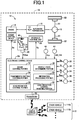
- Fig. 1 is the schematic view showing an arrangement of a drive system 12 of a vehicle 10 to be controlled by a control apparatus according to the present invention, and major portions of the control apparatus to perform various controls of the vehicle 10.
- the drive system 12 is provided with an engine 14 functioning as a drive power source, an automatic transmission 16 connected directly or indirectly via a damper (not shown) or any other device to the engine 14, a differential gear device 18 connected to an output rotary member of the automatic transmission 16 and a pair of axles 20 connected to the differential gear device 18.
- a drive force (drive torque” or “drive power” unless otherwise distinguished from the drive force) of the engine 14 is transmitted to the automatic transmission 16, and is transmitted from the automatic transmission 16 to drive wheels 22 of the vehicle 10 through the differential gear device 18 and other devices.
- the engine 14 is provided with an engine control device 24 including an electronic throttle device, a fuel injection device, an ignition device and other devices that are required for controlling an output of the engine 14.
- the engine control device 24 is controlled, by an electronic control device 50 (that will be described below), based on an operation amount ⁇ acc of an accelerator pedal that corresponds to a required drive force of the vehicle 10 required by an operator of the vehicle 10, whereby an engine torque Te of the engine 14 is controlled.
- a throttle opening degree tap i.e., a degree of opening of a throttle valve included in the electronic throttle device, is also a value corresponding to the required drive force.
- the automatic transmission 16 is a step-variable transmission that constitutes a part of a power transmitting path between the engine 14 and the drive wheels 22.
- the automatic transmission 16 is a known planetary gear automatic transmission including, for example, a plurality of planetary gear devices and a plurality of hydraulically operated frictional coupling devices (hereinafter referred to as "coupling devices CB") such as clutches and brakes.
- the coupling devices CB are selectively placed in engaged, slipped or released states, with their torque capacities being changed according to engaging hydraulic pressures applied thereto, which are regulated by respective solenoid-operated valves or the like incorporated within a hydraulic control unit (hydraulic control circuit) 26.
- a selected one of a plurality of gear positions is established by engagement of one or ones of the coupling devices CB. That is, an operation state of each of the coupling devices CB is controlled, depending on, for example, an operation of the accelerator pedal by the vehicle operator and a running speed V of the vehicle, by the electronic control device 50, whereby one of the gear positions is switched to another of the gear positions (namely, the plurality of gear positions are selectively established).
- a clutch C1 is one of the coupling devices CB, and functions as an input clutch of the automatic transmission 16.
- the clutch C1 is disposed in a power transmitting path between the engine 14 and the drive wheels 22, so as to function also as a connecting/disconnecting device configured to selectively connect and disconnect the power transmitting path (namely, selectively allowing and inhibiting transmission of the drive force through the power transmitting path).
- the automatic transmission 16 is placed in the neutral state with the clutch C1 being placed in its released state.
- the automatic transmission 16 may be constituted by a belt type or other type continuously variable transmission in place of the step-variable transmission.
- the vehicle 10 is provided with a transceiver 28.
- the transceiver 28 is a device configured to communicate with a site or center 100 that is a facility existing apart from the vehicle 10, so that the electronic control device 50 provided in the vehicle 10 transmits and receives various informations to and from the center 100 via the transceiver 28.
- the center 100 functions as a server, and is configured to receive, process, store and provide various informations.
- the center 100 transmits and receives various informations to and from other vehicles 110a, 110b, « (hereinafter referred to as "other vehicles 110"), as well as to and from the vehicle 10.
- Each of the other vehicles 110 has substantially the same construction as the vehicle 10 and basically has substantially the same functions as the vehicle 10.
- the center 100 and the other vehicles 110 can be considered as external devices that are located outside the vehicle 10. It can be considered that the electronic control device 50 of the vehicle 10 cooperates with the center 100 and electronic control devices (each of which functionally corresponds to the electronic control device 50) of the other vehicles 110 to constitute a vehicle control system in which the various informations are shared with one another.
- the vehicle 10 is provided with the electronic control device 50 as a controller including the control apparatus constructed according to the present invention.
- the electronic control device 50 is configured to control various devices of the vehicle 10 such as the engine 14 and automatic transmission 16.
- the electronic control device 50 includes a so-called microcomputer incorporating a CPU, a ROM, a RAM and an input-output interface.
- the CPU performs control operations of the vehicle 10, by processing various input signals, according to control programs stored in the ROM, while utilizing a temporary data storage function of the RAM.
- the electronic control device 50 may be constituted by two or more control units exclusively assigned to perform different control operations such as engine control operations and transmission shifting control operations.
- the electronic control device 50 receives various input signals based on values detected by respective sensors provided in the vehicle 10. Specifically, the electronic control device 50 receives: an output signal of an engine speed sensor 30 indicative of an engine speed Ne which is a rotation speed of the engine 14; an output signal of an input speed sensor 32 indicative of a transmission input speed Ni which is an input rotation speed of the automatic transmission 16; an output signal of an output speed sensor 34 indicative of a transmission output speed No which is an output rotation speed of the automatic transmission 16 and which corresponds to a running speed V of the vehicle 10; an output signal of an accelerator operation amount sensor 36 indicative of an operation amount ⁇ acc which represents a degree of acceleration of the vehicle 10 required by a vehicle operator; an output signal of a throttle opening degree sensor 38 indicative of the throttle opening degree tap; an output signal of a shift position sensor 40 indicative of an operation position POSsh of a manually operated shifting member in the form of a shift lever 46 provided in the vehicle 10; an output signal of a location sensor 42 including a GPS antenna and indicative of information Svp (hereinafter
- the electronic control device 50 generates various output signals which are supplied to various devices such as the engine control device 24 and the hydraulic control unit 26 and which include an engine control command signal Se for controlling the engine 14; and hydraulic control command signals Sp for controlling the operation states of the coupling devices CB.
- the hydraulic control command signals Sp are command signals (drive currents) to be supplied to the hydraulic control circuit 26 for driving solenoid-operated valves or the like that regulate engaging hydraulic pressures PRcb to be applied to hydraulic actuators of the coupling devices CB.
- the electronic control device 50 sets hydraulic pressure command values (command pressures) corresponding to the engaging hydraulic pressures PRcb to be applied to the hydraulic actuators, and outputs drive currents corresponding to the hydraulic pressure command values.
- the shift lever 46 is operable to be placed in a selected one of a plurality of operation positions POSsh that consist of, for example, a parking position P, a reverse position R, a neutral position N, a drive position D and manual position M.
- POSsh a parking position P
- R a reverse position
- N a neutral position
- D a drive position
- M manual position M.
- the shift lever 46 is placed in the parking position P, the automatic transmission 16 is placed in its parking position in which the automatic transmission 16 is placed in its neutral state and rotation of an output shaft of the automatic transmission 16 is mechanically inhibited (locked).
- the shift lever 46 With the shift lever 46 being placed in the reverse position R, the automatic transmission 16 is placed in its reverse drive position for enabling the vehicle 10 to run in a reverse direction.
- the neutral position N the automatic transmission 16 is placed in its neutral position in which the automatic transmission 16 is placed in its neutral state.
- the automatic transmission 16 With the shift lever 46 being placed in the drive position D, the automatic transmission 16 is placed in its forward drive position for establishing an automatic shifting mode in which the automatic transmission 16 is automatically shifted to one of all forward gear positions to enable the vehicle 10 to run in a forward direction.
- the shift lever 46 With the shift lever 46 being placed in the manual position M, the automatic transmission 16 is placed in its manual shift position for establishing a manual shifting mode in which the automatic transmission 16 can be switched from one of the gear positions to another by operation of the vehicle operator.
- the manual position M is provided with a shift-up position (+) and a shift-down position (-), so that the transmission 16 is shifted up each time the shift lever 46 is shifted to the shift-up position (+), while being shifted down each time the shift lever 46 is shifted to the shift-down position (-).
- While the automatic shifting mode is established with the shift lever 46 being placed in the drive position D as one of the operation positions POSsh, the automatic transmission 16 is automatically shifted to one of the forward gear positions, which is selected in accordance with a known shifting map.
- the manual shifting mode is established with the shift lever 46 being placed in the manual position M as one of the operation positions POSsh, the automatic transmission 16 is shifted to one of the forward gear positions, which is selected in accordance with manual operation of the shift lever 46 made by the vehicle operator.
- the drive-mode selector switch 44 is an operating member that is to be operated by the vehicle operator, for selecting a desired one of drive modes with which the vehicle is to run.
- the drive modes consist of, for example, a normal mode, a sport mode (or power mode) and an economy mode.
- the normal mode is for enabling the vehicle 10 to run in a state that is satisfactory in both of the drive force performance and the fuel efficiency performance.
- the sport mode is for enabling the vehicle 10 to run in a state in which more importance is given to the drive force performance than to the fuel efficiency performance, as compared with the state of the normal mode.
- the economy mode is for enabling the vehicle 10 to run in a state in which more importance is given to the fuel efficiency performance than to the drive force performance, as compared with the state of the normal mode.
- the electronic control device 50 includes an engine control means or portion in the form of an engine control portion 52, a transmission shifting control means or portion in the form of a transmission shifting control portion 54, and a load reduction control means or portion in the form of a load reduction control portion 56, for performing various controls in the vehicle 10.
- the engine control portion 52 controls the engine control device 24, so as to obtain a required engine torque Te.
- the engine control portion 52 calculates a required drive torque Tdem as a required drive force, for example, by applying the accelerator operation amount ⁇ acc and the running velocity V to a predetermined or stored relationship (e.g., drive force map) that is obtained by experimentation or determined by an appropriate design theory.
- the engine control portion 52 takes account of the gear position of the automatic transmission 16, and outputs the engine control command signal Se for controlling the engine 14 such that the engine torque Te providing the required drive torque Tdem is obtained.
- a required drive force Fdem [N] acting on the drive wheels 22, a required drive power Pdem [W] acting on the drive wheels 22, a required output torque Todem outputted from the automatic transmission 16, a required input torque Tidem inputted to the automatic transmission 16, or a required engine torque Tedem outputted from the engine 14 may be used in place of the required drive torque Tdem [Nm] acting on the drive wheels 22.
- the accelerator operation amount ⁇ acc [%], the throttle opening degree tap [%] or an amount [g/sec] of air intake by the engine 14 may be used as the above-described required drive force.
- the transmission shifting control portion 54 executes a shifting control of the automatic transmission 16.
- the transmission shifting control portion 54 establishes the automatic shifting mode.
- the transmission shifting control portion 54 determines whether a shifting action is to be executed in the automatic transmission 16, using the predetermined relationship (e.g., shifting map), and outputs the hydraulic control command signals Sp that is supplied to the hydraulic control circuit 26, for controlling the operation states of the coupling devices CB, so as to automatically switch one of the gear positions of the automatic transmission 16 to another of the gear positions as needed.
- the transmission shifting control portion 54 establishes the manual shifting mode.
- the transmission shifting control portion 54 that is supplied to the hydraulic control circuit 26, for controlling the operation states of the coupling devices CB, so as to switch one of the gear positions of the automatic transmission 16 to another of the gear positions in accordance with operation of the shift lever 46 made by the vehicle operator, without depending on the above-described shifting map.
- the shifting map represents a relationship, for example, between the transmission output speed No (that corresponds to the running speed V) and the accelerator operation amount ⁇ acc (that corresponds to the required drive torque Tdem and the throttle opening degree tap) that are indicated as parameters in two-dimensional coordinates, with shifting boundary lines (shift-up boundary lines and shift-down boundary lines) based on which the determination as to the shifting action is to be executed in the automatic transmission 16 is to be made.
- the load reduction control portion 56 is configured, when predetermined control-execution allowing conditions are satisfied, to execute a fuel-efficiency increase control for stopping the engine 14 and/or disconnecting the engine 14 from the drive wheels 22.
- the load reduction control portion 56 disconnects the engine 14 from the drive wheels 22, by placing the clutch C1 into its released state and thereby cutting off transmission of the drive force through the power transmitting path between the engine 14 and the drive wheels 22.
- the load reduction control portion 56 stops the engine 14, by supplying the engine control portion 52 with a command requesting, for example, a fuel cut (F/C) suspending a fuel supply to the engine 14.
- a command requesting for example, a fuel cut (F/C) suspending a fuel supply to the engine 14.
- F/C fuel cut
- the rotation stop of the engine 14 is dependent on, for example, not only whether the fuel cut is being made but also whether the engine 14 is disconnected from the drive wheels 22.
- the load reduction control portion 56 disconnects the engine 14 from the drive wheels 22, by supplying the transmission shifting control portion 54 with a command requesting the clutch C1 to be released.
- the control-execution allowing conditions are predetermined conditions that are to be satisfied to execute the above-described fuel-efficiency increase control, and relate to, for example, a length of time through which the accelerator pedal is held in the released position, the running speed V, a wheel brake operating force, an operation angle of a steering wheel, a distance between vehicles and a need to warm up the engine 14.
- the engine 14 When the engine 14 is not stopped in the fuel-efficiency increase control, the engine 14 is placed, for example, in its idling state. Further, the releasing of the clutch C1 may be a full release that is made by controlling the engaging hydraulic pressure of the clutch C1 to substantially zero. However, for enabling the vehicle 10 to be started or accelerated with a better responsiveness after completion of the fuel-efficiency increase control, it is preferable to place the clutch C1 in its partially-released state (engagement standby state), by supplying the clutch C1 with a certain engaging hydraulic pressure that does not cause a torque capacity to be generated in the clutch C1.
- the fuel-efficiency increase control can be executed in various kinds of manners or forms such as an idle stop control, a deceleration economy running control, a free-run control, a neutral control and a neutral inertia running control, for example.
- Fig. 2 is a view explaining a case where the fuel-efficiency increase control is not executed in any one of the forms and also cases where the fuel-efficiency increase control is executed in the respective forms.
- the engine 14 in a normal control without execution of the fuel-efficiency increase control, the engine 14 is activated or operated with the clutch C1 being engaged during stop or running of the vehicle 10.
- the idle stop control as one of the forms of fuel-efficiency increase control, the engine 14 is stopped with the clutch C1 being released during stop of the vehicle 10.
- the engine 14 In the deceleration economy running control as one of the forms of the fuel-efficiency increase control, the engine 14 is stopped with the clutch C1 being released during an inertia running of the vehicle 10 at a low running speed (namely, during a decelerated running shortly before being stopped). In the free-run control as one of the forms of the fuel-efficiency increase control, the engine 14 is stopped with the clutch C1 being released during an inertia running of the vehicle 10 at a middle or high speed. In the neutral control as one of the forms of the fuel-efficiency increase control, the engine 14 is operated in its idling state with the clutch C1 being released during stop of the vehicle 10. In the neutral inertia running control as one of the forms of the fuel-efficiency increase control, the engine 14 is operated in its idling state with the clutch C1 being released during an inertia running of the vehicle 10.
- the execution of the fuel-efficiency increase control leads to an improvement in an actual fuel efficiency, but could cause a delay in start or acceleration, due to necessity of restart of the engine 14 or engagement of the clutch C1 when the vehicle 10 should be restarted or accelerated again. Such a reduction in the responsiveness upon start or acceleration could be a factor causing the vehicle operator to feel uncomfortable. It might be possible to inhibit the fuel-efficiency increase control (namely, not execute the fuel-efficiency increase control) when an acceleration intention of the vehicle operator is high as in a case of the manual shifting mode and/or the sport mode being selected. However, since the improvement of the fuel efficiency is reduced by the inhibition of the fuel-efficiency increase control, it is desirable to minimize the inhibition of the fuel-efficiency increase control as long as the vehicle operator does not feel uncomfortable.
- a vehicle operator is less likely to feel uncomfortable with respect to the responsiveness upon start or acceleration in an area in which a difference between an acceleration representative value representing an acceleration of the vehicle 10 required by the vehicle operator when the fuel-efficiency increase control has been executed and an acceleration representative value representing an acceleration of the vehicle 10 required by the vehicle operator when the fuel-efficiency increase control has not been executed, is small.
- the vehicle operator is more likely to feel uncomfortable with respect to the responsiveness upon start or acceleration in an area in which the above-described difference is large.
- control execution condition determining a condition (hereinafter referred to as "control execution condition") that is to be satisfied for executing the fuel-efficiency increase control, based on the above-described tendency, and executing the fuel-efficiency increase control, depending on whether the control execution condition is satisfied or not.
- the acceleration representative value representing the actually required acceleration may be, for example, a drive-force related value such as a required drive force and an amount of change of the required drive force.
- the throttle opening degree tap is used as an example of the required drive force.
- the load reduction control portion 56 is capable of executing the fuel-efficiency increase control in various manners or forms such as the above-described idle stop control, deceleration economy running control, free-run control, neutral control and neutral inertia running control.
- the electronic control device 50 further includes a vehicle-state determining means or portion in the form of a vehicle-state determining portion 58, an information processing means or portion in the form of an information processing portion 60 and a load-reduction control inhibiting means or portion in the form of a load-reduction control inhibiting portion 62, for performing various controls for suitably inhibiting the fuel-efficiency increase control.
- the vehicle-state determining portion 58 determines whether the fuel-efficiency increase control has been executed or not during the last stop or last inertia running of the vehicle 10.
- the idle stop control or neutral control as one of the forms of the fuel-efficiency increase control could have been executed during the last stop.
- the vehicle 20 is re-accelerated after the inertia running, for example, the deceleration economy running control, free-run control or neutral inertia running control as one of the forms of the fuel-efficiency increase control could have been executed during the last inertia running.
- the information processing portion 60 determines in which form or manner the fuel-efficiency increase control has been executed, namely, obtains a content of the fuel-efficiency increase control executed during the last stop or last inertia running.
- the information processing portion 60 Upon restart or re-acceleration after stop or inertia running of the vehicle 10, the information processing portion 60 generate a control information Ic containing: (i) a first data (control signal) indicative of status of execution of the fuel-efficiency increase control (i.e., data indicative of whether the fuel-efficiency increase control has been executed or not, and also the content of the fuel-efficiency increase control in case of the execution), (ii) a second data indicative of the acceleration representative value (representing the acceleration required upon restart or re-acceleration of the vehicle 10) in the form of the throttle opening degree tap and an amount ⁇ tap (hereinafter referred to as "throttle change amount ⁇ tap") of change of the throttle opening degree tap, and (iii) a third data in the form of the location information Svp indicative of the current location of the vehicle 10.
- a first data indicative of status of execution of the fuel-efficiency increase control
- a second data indicative of the acceleration representative value (representing the acceleration required upon restart or re-acceleration
- the first data and second data are associated with the third data in the generated control information Ic.
- the control information Ic is generated for each one of the various manners or forms of the fuel-efficiency increase control.
- the information processing portion 60 transfers the control information Ic to the center 100 via the transceiver 28.
- the throttle change amount ⁇ tap represents the change amount within a length of time corresponding to a control cycle, and corresponds to a rate of change of the throttle opening degree tap.
- the center 100 calculates a throttle opening-degree difference T that is a difference between the throttle opening degree tap (as an example of the acceleration representative value) when the fuel-efficiency increase control has been executed in each area and the throttle opening degree tap when the fuel-efficiency increase control has not been executed in the same area, namely, a difference between the throttle opening degree tap with execution of the fuel-efficiency increase control in each control information Ic and the throttle opening degree tap without execution of the fuel-efficiency increase control in the control informations Ic that are same in terms of the location information Svp.
- a throttle opening-degree difference T is a difference between the throttle opening degree tap (as an example of the acceleration representative value) when the fuel-efficiency increase control has been executed in each area and the throttle opening degree tap when the fuel-efficiency increase control has not been executed in the same area, namely, a difference between the throttle opening degree tap with execution of the fuel-efficiency increase control in each control information Ic and the throttle opening degree tap without execution of the fuel-efficiency increase control in the control informations Ic that are same in terms of the location information
- the calculation of the throttle opening-degree difference T is made for each of the forms or manners of the fuel-efficiency increase control. Where there are a plurality of values of the throttle opening degree tap with or without execution of the fuel-efficiency increase control in the same area, an average of the plurality of values is used, for example.
- the center 100 calculates a throttle change-amount difference ⁇ T that is a difference between the throttle change amount ⁇ tap (as an example of the acceleration representative value) when the fuel-efficiency increase control has been executed in each area and the throttle change amount ⁇ tap when the fuel-efficiency increase control has not been executed in the same area, namely, a difference between the throttle change amount ⁇ tap with execution of the fuel-efficiency increase control in each control information Ic and the throttle change amount ⁇ tap without execution of the fuel-efficiency increase control in the control informations Ic that are same in terms of the location information Svp.
- the calculation of the throttle change-amount difference ⁇ T is made for each of the forms or manners of the fuel-efficiency increase control.
- the center 100 determines whether the above-described throttle opening degree T is greater a first threshold value Tf or not, and determines whether the above-described throttle change-amount difference ⁇ T is greater than a second threshold value ⁇ Tf.
- the center 100 is configured, when the throttle opening-degree difference T and the throttle change-amount difference ⁇ T in an area are greater than the respective first and second threshold values Tf, ⁇ Tf, to determine that the area (i.e., the vehicle location represented by the location information Svp) as an inhibited area in which the fuel-efficiency increase control is inhibited from being executed.
- the area i.e., the vehicle location represented by the location information Svp
- an area indicated by the location information Svp that is associated with the acceleration representative value is set as the inhibited area in which the execution of the fuel-efficiency increase control is inhibited.
- the term "area” may be interpreted to mean a zone having a predetermined range, wherein it is considered that a tendency of the acceleration required by a vehicle driver is substantially the same in any part of the zone (area) so that the control information ID in any part of the zone (area) can be treated as information relating to the same point.
- the threshold value (first threshold value Tf and second threshold value ⁇ Tf) is an upper limit value, beyond which it is determined that the acceleration representative value representing the acceleration after execution of the fuel-efficiency increase control is increased to such a degree that represents that vehicle operator feels uncomfortable with delay in the responsiveness upon start or acceleration.
- the threshold value (first threshold value Tf and second threshold value ⁇ Tf) may be a given value that varies depending on area (i.e., vehicle location represented by the location information Svp), for example, depending on type of running road such as flat road, uphill road, downhill road, road intersection and road junction.
- the center 100 has a control inhibition map indicating an inhibited area or areas in which execution of the fuel-efficiency increase control is to be inhibited. When an area is newly set as the inhibited area, the control inhibition map is updated to reflect the new setting. It is noted that the control inhibition map is prepared for each one of the various forms of the fuel-efficiency increase control.
- the information processing portion 60 receives, from the center 100 via the transceiver 28, an information Imap containing the control inhibition map prepared for each one of the various forms of the fuel-efficiency increase control, as needed.
- the load-reduction control inhibiting portion 62 obtains the location information Svp indicative of the current location of the vehicle 10, and determines whether the current location of the vehicle 10 corresponds to an area in which execution of the fuel-efficiency increase control is to be inhibited, by using the control inhibition map contained in the information Imap. This determination is made for each of the forms of the fuel-efficiency increase control.
- the load-reduction control inhibiting portion 62 outputs a command inhibiting the execution of the fuel-efficiency increase control, and the inhibiting command is supplied to the load reduction control portion 56.
- the load-reduction control inhibiting portion 62 when having determined that the current location of the vehicle 10 does not correspond to the area in which the fuel-efficiency increase control is to be inhibited, the load-reduction control inhibiting portion 62 outputs a command allowing the execution of the fuel-efficiency increase control, and the allowing command is supplied to the load reduction control portion 56. It is noted that the inhibiting command and the allowing command are outputted for each of the forms of the fuel-efficiency increase control.
- the control inhibition map which is stored in the center 100, is a map that is indicative of the inhibited area or areas the fuel-efficiency increase control is to be inhibited from being executed.
- the control inhibition map corresponds to a control inhibition condition which relates to the location of the vehicle 10 and which is to be satisfied for inhibiting execution of the fuel-efficiency increase control. It is preferable that the control inhibition map has been prepared even for an area in which the vehicle 10 has never run and will run for the first time. To this end, the control inhibition map for such an area is prepared based on the control information Ic transferred from the other vehicle 110.
- the load-reduction control inhibiting portion 62 inhibits the fuel-efficiency increase control, depending on whether the control inhibition condition is satisfied or not, wherein the control inhibition condition is prepared based on the control information Ic which is transferred from at least one of the other vehicles 110 and which contains the data indicative of the acceleration representative value representing the acceleration required by the vehicle operator and associated with the location information Svp.
- the control inhibition condition is set for each of the various forms of the fuel-efficiency increase control.
- the load-reduction control inhibiting portion 62 inhibits the fuel-efficiency increase control from being executed in the one or ones of the various forms.
- control inhibition map which is stored in the center 100, is a map indicating that execution of the fuel-efficiency increase control is allowed in an area or areas other than the above-described inhibited area or areas.
- control inhibition map may be interpreted to correspond to a control execution condition which relates to the location of the vehicle 10 and which is to be satisfied for allowing execution of the fuel-efficiency increase control.
- the load reduction control portion 56 executes the fuel-efficiency increase control, depending on whether the control execution condition is satisfied or not, wherein the control execution condition is prepared based on the control information Ic which is transferred from at least one of the other vehicles 110 and which contains the data indicative of the acceleration representative value representing the acceleration required by the vehicle operator and associated with the location information Svp.
- the load reduction control portion 56 does not execute the fuel-efficiency increase control in the above-described area indicated by the location information Svp.
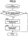
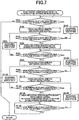
- FIG. 3-5 is a flow chart showing a control routine that is executed to restrain reduction in improvement of fuel efficiency, which reduction could be caused when the fuel-efficiency increase control is inhibited.
- the control routines of Figs. 3 and 5 are executed in the electronic control device 50.
- the control routine of Fig. 4 is executed in the center 100.
- step SA10 (hereinafter simply referred to as "SA10" as well as the other steps) corresponding to the function of the vehicle-state determining portion 58.
- SA10 is implemented upon restart or re-acceleration after stop or inertia running of the vehicle 10, to determine whether the fuel-efficiency increase control has been executed during the stop or inertia running. If an affirmative determination is made at the SA10, the control flow goes to SA20 corresponding to the function of the information processing portion 60, to obtain the content of the fuel-efficiency increase control.
- control flow goes to SA30 corresponding to the function of the information processing portion 60, to generate the control information Ic containing: (i) the first data (control signal) indicative of the status of execution of the fuel-efficiency increase control, (ii) the second data indicative of the acceleration representative value in the form of the throttle opening degree tap and the throttle change amount ⁇ tap and (iii) the third data in the form of the location information Svp, wherein the first data and second data are associated with the third data in the generated control information Ic.
- the control information Ic is thus generated for each one of the various forms of the fuel-efficiency increase control, and the generated control information Ic is transferred to the center 100 via the transceiver 28. It is noted that the SA30 is implemented also after implementation of the SA20.
- the control routine of Fig. 4 is initiated with SB 10 corresponding to the function of a required-acceleration difference calculating portion.
- the SB 10 is followed by SB20 corresponding to the function of a required acceleration difference determining portion.
- the SB20 it is determined whether the throttle opening degree T is greater than the first threshold value Tf and also the throttle change-amount difference ⁇ T is greater than the second threshold value ⁇ Tf. If a negative determination is made at the SB20, one cycle of execution of the control routine is terminated. If an affirmative determination is made at the SB20, the control flow goes to SB30 corresponding to the function of an inhibited-area setting portion. In the SB30, an area indicated by the location information Svp is set as the inhibited area in which execution of the fuel-efficiency increase control is to be inhibited.
- the SB30 is followed by SB40 corresponding to a map updating portion, to update the control inhibition map, which has been prepared for each one of the various forms of the fuel-efficiency increase control, such that the updated control inhibition map reflects the inhibited area setting made at the SB30.
- the control routine of Fig. 5 is initiated with SC10 corresponding to the function of the information processing portion 60.
- the SC10 is implemented after power-ON of the vehicle 10, to receive the information Imap containing the control inhibition map prepared for each one of the various forms of the fuel-efficiency increase control, from the center 100 via the transceiver 28.
- the SC10 is followed by SC20 corresponding to the load-reduction control inhibiting portion 62, to obtain the location information Svp indicative of the current location of the vehicle 10.
- SC30 corresponding to the load-reduction control inhibiting portion 62 is implemented to determine whether the current location of the vehicle 10 corresponds to the inhibited area in which the fuel-efficiency increase control is inhibited from being executed in each one of the various manners or forms, by using the control inhibition map contained in the information Imap. This determination is made for each one of the various forms of the fuel-efficiency increase control. If an affirmative determination is made at the SC30, the control flow goes to SC40 corresponding to the load-reduction control inhibiting portion 62, to inhibit the fuel-efficiency increase control from being executed in the corresponding one or ones of the various forms. If a negative determination is made at the SC30, the control flow goes to SC50 corresponding to the load-reduction control inhibiting portion 62, to allow the fuel-efficiency increase control to be executed in the corresponding one or ones of the various forms.
- the fuel-efficiency increase control is executed for stopping the engine 14 and/or disconnecting the engine 14 from the drive wheels 22 in each area, depending on whether the control execution condition is satisfied or not, wherein the control execution condition is set based on information which is transferred from other vehicle or vehicles 110 and which includes the acceleration representative value (representing the required acceleration of the other vehicle or vehicles 110 required by the vehicle operator or operators) that is associated with the location information Svp indicative of the same area.
- the control execution condition is set based on information which is transferred from other vehicle or vehicles 110 and which includes the acceleration representative value (representing the required acceleration of the other vehicle or vehicles 110 required by the vehicle operator or operators) that is associated with the location information Svp indicative of the same area.
- the engine 14 can be stopped and/or the engine 14 can be disconnected from the drive wheels 22, depending on the actual tendency of the required acceleration in each area. It is therefore possible to restrain reduction in improvement of fuel efficiency, which reduction could be caused in an arrangement in which the fuel-efficiency increase control is inhibited always when the acceleration intention of the operator is high.
- the fuel-efficiency increase control is not executed, namely, the engine 14 is not stopped and the engine 14 is not disconnected from the drive wheels 22, in the area indicated by the location information, where the difference between the acceleration representative value with execution of the fuel-efficiency increase control and the acceleration representative value without execution of the fuel-efficiency increase control is greater than the threshold value.
- the above-described threshold value (first threshold value Tf, second threshold value ⁇ Tf), based on which the above-described difference is determined to be large or small, is a given value that varies depending on an area indicated by the location information Svp that is associated with the acceleration representative value.
- the determination as to whether the above-described difference is large or small i.e., the determination as to whether the fuel-efficiency increase control should be inhibited or allowed in each area can be made suitably depending on the type of running road (such as flat road, uphill road and downhill road) in the same area.
- control inhibition map stored in the center 100 as an example of the control inhibition condition which relates to the location of the vehicle and which is to be satisfied for inhibiting execution of the fuel-efficiency increase control.
- control inhibition condition in other words, control execution condition
- the control inhibition condition is set by taking account of an acceleration intention of the vehicle operator in addition to the control inhibition map. It is considered that the vehicle operator feels uncomfortable with delay in the responsiveness upon start or acceleration of the vehicle, by a degree that varies depending on a degree of the acceleration intention of the vehicle operator. Thus, the degree of the acceleration intention of the vehicle operator is reflected in the control inhibition condition.
- the degree of the acceleration intention of the vehicle operator is represented by, for example, which one of the drive force performance and the fuel efficiency performance is given more importance by the vehicle operator.
- a case where the acceleration intention of the vehicle operator is high corresponds to a case where the vehicle operator gives more importance to the drive force performance rather than to the fuel efficiency performance, such as when the manual position M is selected as the operation position POSsh (i.e., when the manual shifting mode is established) and when the sport mode is selected by the drive-mode selector switch 44.
- a case where the acceleration intention of the vehicle operator is not high (or low) corresponds to a case where the vehicle operator gives more importance to the fuel efficiency performance rather than to the drive force performance, such as when the drive position D is selected as the operation position POSsh (i.e., case where the automatic shifting mode is established) and when the normal mode (or the economy mode) is selected by the drive-mode selector switch 44.
- the load-reduction control inhibiting portion 62 allows execution of the fuel-efficiency increase control in the same area when the operator's acceleration intention is low (for example, when the economy mode is selected), and inhibits execution of the fuel-efficiency increase control in the same area when the operator's acceleration intention is high (for example, when the manual shifting mode or sport mode is selected).
- the load-reduction control inhibiting portion 62 allows execution of the fuel-efficiency increase control when the vehicle operator gives more importance to the fuel efficiency performance rather than to the drive force performance.
- the load reduction control portion 56 determines whether executing the fuel-efficiency increase control or not, depending on information (e.g., control information Ic) of the acceleration representative value representing the required acceleration and also which one of the drive force performance and the fuel efficiency performance is given more importance by the vehicle operator, and executes the fuel-efficiency increase control even in an area in which the above-described difference in terms of the required acceleration is greater than the above-described threshold value, when the fuel efficiency performance is given more importance.
- the load-reduction control inhibiting portion 62 allows the fuel-efficiency increase control to be executed in an area in which the execution of the fuel-efficiency increase control is not inhibited in the control inhibition map (i.e., in an area in which the difference between the acceleration representative value with execution of the fuel-efficiency increase control and the acceleration representative value without execution of the fuel-efficiency increase control tends to be small), irrespective of a degree of the acceleration intention of the vehicle operator. That is, even when the vehicle operator gives more importance to the drive force performance rather than to the fuel efficiency performance, the load-reduction control inhibiting portion 62 allows execution of the fuel-efficiency increase control in an area in which the above-described difference in terms of the required acceleration is not greater than the above-described threshold value.
- the load reduction control portion 56 determines whether executing the fuel-efficiency increase control or not, depending on information of the acceleration representative value representing the required acceleration and also which one of the drive force performance and the fuel efficiency performance is given more importance by the vehicle operator, and executes the fuel-efficiency increase control in an area in which the above-described difference in terms of the required acceleration is not greater than the above-described threshold value, even when the drive force performance is given more importance.
- it is determined whether execution of the fuel-efficiency increase control is to be inhibited or not, depending on the information of the acceleration representative value representing the required acceleration and also which one of the drive force performance and the fuel efficiency performance is given more importance by the vehicle operator.
- control inhibition condition (in other words, control execution condition) is set by using the above-described difference in the acceleration representative value representing the acceleration required by the operator between the case with execution of the fuel-efficiency increase control and the case without execution of the fuel-efficiency increase control. It can be considered that the vehicle operator is less likely to feel uncomfortable with delay in the responsiveness upon start or acceleration in an area in which the acceleration representative value representing the acceleration required by the operator tends to be small. On the other hand, it can be considered that the vehicle operator is more likely to feel uncomfortable with delay in the responsiveness upon start or acceleration in an area in which the acceleration representative value tends to be large. In view of these, in the present third embodiment, the control inhibition condition is set by using the acceleration representative value.
- the arrangements of the above-described first and second embodiments are replaced by an arrangement in which the center 100 determines whether the throttle opening degree tap contained in each control information Ic that contains the location information Svp is greater than a first threshold value tapf or not, and also determines whether the throttle change amount ⁇ tap contained in each control information Ic that contains the location information Svp is greater than a second threshold value tapf or not.
- Each of the throttle opening degree tap and the throttle change amount ⁇ tap may be, for example, a value with execution of the fuel-efficiency increase control, or may be an average of a value with execution of the fuel-efficiency increase control and a value without execution of the fuel-efficiency increase control.
- the center 100 sets an area indicated by the location information Svp, as the inhibited area in which the fuel-efficiency increase control is to be inhibited.
- the area indicated by the location information Svp is set as the inhibited area in which the fuel-efficiency increase control is to be inhibited.
- the threshold value (first threshold value tapf and second threshold value ⁇ tapf) is an upper limit value, beyond which it is determined that the acceleration representative value representing the acceleration after execution of the fuel-efficiency increase control is increased to such a degree that represents that vehicle operator desires quick response upon start or acceleration.
- the threshold value (first threshold value tapf and second threshold value ⁇ tapf) may be a value that varies depending on area (i.e., vehicle location represented by the location information Svp), for example, depending on type of road such as flat road, uphill road and downhill road.
- the load reduction control portion 56 does not execute the fuel-efficiency increase control in an area indicated by the location information Svp.
- control inhibition condition may be set by taking account of the acceleration intention of the vehicle operator in addition to the control inhibition map, as in the above-described second embodiment. That is, even in an area in which the above-described difference in terms of the required acceleration is greater than the above-described threshold value, the load-reduction control inhibiting portion 62 may allow execution of the fuel-efficiency increase control when the vehicle operator gives more importance to the fuel efficiency performance rather than to the drive force performance.
- the load reduction control portion 56 may determine whether executing the fuel-efficiency increase control or not, depending on information (e.g., control information Ic) of the acceleration representative value representing the required acceleration and also which one of the drive force performance and the fuel efficiency performance is given more importance by the vehicle operator, and may execute the fuel-efficiency increase control even in an area in which the above-described difference in terms of the required acceleration is greater than the above-described threshold value, when the fuel efficiency performance is given more importance.
- information Ic control information of the acceleration representative value representing the required acceleration and also which one of the drive force performance and the fuel efficiency performance is given more importance by the vehicle operator
- the load-reduction control inhibiting portion 62 may allow the fuel-efficiency increase control to be executed in an area in which the execution of the fuel-efficiency increase control is not inhibited in the control inhibition map (i.e., in an area in which the difference between the acceleration representative value with execution of the fuel-efficiency increase control and the acceleration representative value without execution of the fuel-efficiency increase control tends to be small), even when the vehicle operator gives more importance to the drive force performance rather than to the fuel efficiency performance.
- the load reduction control portion 56 may determine whether executing the fuel-efficiency increase control or not, depending on information of the acceleration representative value representing the required acceleration and also which one of the drive force performance and the fuel efficiency performance is given more importance by the vehicle operator, and may execute the fuel-efficiency increase control in an area in which the above-described difference in terms of the required acceleration is not greater than the above-described threshold value, even when the drive force performance is given more importance.
- it may be determined whether execution of the fuel-efficiency increase control is to be inhibited or not, depending on the information of the acceleration representative value representing the required acceleration and also which one of the drive force performance and the fuel efficiency performance is given more importance by the vehicle operator.
- Fig. 6 is a flow chart showing control routine that is executed to restrain reduction in improvement of fuel efficiency, which reduction could be caused when the fuel-efficiency increase control is inhibited.
- This control routine is executed, in place of the control routine of Fig. 7 , in the center 100.
- the control routine of Fig. 6 is initiated with SD10 corresponding to the function of an acceleration-requirement determining portion.
- the SD10 is implemented upon reception of the control information Ic, to determine whether the throttle opening degree tap is greater than the first threshold value tapf and also the throttle change amount ⁇ tap is greater than the second threshold value ⁇ tapf in the control information Ic that contains the location information Svp. If a negative determination is made at the SD10, one cycle of execution of the control routine is terminated. If an affirmative determination is made at the SD10, the control flow goes to SD20 corresponding to the function of the inhibited-area setting portion. In the SD20, an area indicated by the location information Svp is set as the inhibited area in which the fuel-efficiency increase control is to be inhibited.
- the SD20 is followed by SD30 corresponding to the map updating portion, to update the control inhibition map, which has been prepared for each one of the various forms of the fuel-efficiency increase control, such that the updated control inhibition map reflects the inhibited area setting made
- the fuel-efficiency increase control is not executed in the same area, so that it is possible to stop the engine 14 and/or disconnect the engine 14 from the drive wheels 22, or neither stop the engine 14 nor disconnect the engine 14 from the drive wheels 22 in each area, in accordance with an actual tendency of the required acceleration in the same area.
- the fuel-efficiency increase control is allowed to stop the engine 14 and/or disconnect the engine 14 from the drive wheels 22 in an area in which the acceleration representative value tends to be small, even when the drive force performance is given more importance, namely, even when the operator's acceleration intention is high.
- the threshold value (first threshold value tapf and second threshold value ⁇ tapf) is a given value that varies depending on an area, and the control execution condition, which is to be satisfied for executing the fuel-efficiency increase control, are determined depending on area, for example, depending on type of running road such as flat road, uphill road and downhill road.
- the inhibition of the fuel-efficiency increase control is limited by setting the control inhibition map.
- the reduction of the actual fuel efficiency is increased.
- the fuel-efficiency increase control is inhibited from being executed in not only one of the various forms but also two or more of the various forms.
- the risk of reduction of the actual fuel efficiency is increased with increase of the number of the inhibited forms.
- the inhibition of the fuel-efficiency increase control is cancelled to restrain the reduction of the actual fuel efficiency.
- the inhibitions of the two or more forms of the fuel-efficiency increase control are cancelled one by one, so as to restrain the reduction of the actual fuel efficiency.
- the vehicle-state determining portion 58 determines whether the actual fuel efficiency is reduced by at least a threshold ratio, namely, determines whether a reduction ratio of the actual fuel efficiency is at least the threshold ratio.
- the reduction ratio of the actual fuel efficiency is, for example, a ratio of reduction of an average of the actual fuel efficiency in the most recent period having a given length of time, relative to an average of the actual fuel efficiency in an earlier period (earlier than the most recent period) having a given length of time, or alternatively, a ratio of reduction of an average of the actual fuel efficiency in the most recent running over a given distance, relative to an average of the actual fuel efficiency in an earlier running (earlier than the most recent running) over a given distance.
- the above-described threshold ratio is an upper limit value, beyond which it is determined that the actual fuel efficiency is considerably reduced to such a degree that represents, for example, a need to cancel the inhibition of the fuel-efficiency increase control.
- Each of the above-described given length of time and given distance is a predetermined range required to, for example, observe the change of the actual fuel efficiency.
- the load-reduction control inhibiting portion 62 cancels the inhibition of the fuel-efficiency increase control, by canceling the control inhibition map.
- the load-reduction control inhibiting portion 62 withdraws the cancellation of the control inhibition map.
- the control inhibition maps are prepared for the respective forms of the fuel-efficiency increase control. In this arrangement, the load-reduction control inhibiting portion 62 cancels the control inhibition maps one by one, or cancels the latest control inhibition map.
- the load-reduction control inhibiting portion 62 keeps inhibiting or allows the fuel-efficiency increase control, depending on the reduction ratio of the actual fuel efficiency. In other words, while not executing the fuel-efficiency increase control, the load reduction control portion 56 executes the fuel-efficiency increase control when the reduction ratio of the actual fuel efficiency is not smaller than the threshold ratio.
- Fig. 7 is a flow chart showing control routine that is executed to restrain reduction in improvement of fuel efficiency, which reduction could be caused when the fuel-efficiency increase control is inhibited. This control routine is executed in the electronic control device 50.
- the control routine of Fig. 7 is initiated with SE10 corresponding to the function of the vehicle-state determining portion 58.
- the SE10 is implemented when any one of the modes of the fuel-efficiency increase control is subjected to a corresponding one of the control inhibition maps.
- the SE10 after the vehicle has run for at least the given distance, it is determined whether the reduction ratio of the actual fuel efficiency is at least the threshold ratio. If a negative determination is made at the SE10, one cycle of execution of the control routine is terminated. If an affirmative determination is made at the SE10, the control flow goes to SE20 corresponding to the function of the load-reduction control inhibiting portion 62, to cancel the control inhibition map directed to the idle stop control as one of the modes of the fuel-efficiency increase control.
- SE30 corresponding to the function of the vehicle-state determining portion 58, after the vehicle has run for at least the given distance, it is determined whether the reduction ratio of the actual fuel efficiency is still at least the threshold ratio. If a negative determination is made at the SE30, the control flow goes to SE40 corresponding to the function of the load-reduction control inhibiting portion 62, to withdraw the cancellation of the control inhibition map directed to the idle stop control, which cancellation was made at the SE20. The SE40 is followed by the SE10. If an affirmative determination is made at the SE30, the control flow goes to SE50 corresponding to the function of the load-reduction control inhibiting portion 62, to cancel the control inhibition map directed to the deceleration economy running control as one of the modes of the fuel-efficiency increase control.
- SE60 corresponding to the function of the vehicle-state determining portion 58, after the vehicle has run for at least the given distance, it is determined whether the reduction ratio of the actual fuel efficiency is still at least the threshold ratio. If a negative determination is made at the SE60, the control flow goes to SE70 corresponding to the function of the load-reduction control inhibiting portion 62, to withdraw the cancellation of the control inhibition map directed to the deceleration economy running control, which cancellation was made at the SE50.
- SE70 is followed by the SE30.
- the control flow goes to SE80 corresponding to the function of the load-reduction control inhibiting portion 62, to cancel the control inhibition map directed to the free-run control as one of the modes of the fuel-efficiency increase control.
- SE90 corresponding to the function of the vehicle-state determining portion 58, after the vehicle has run for at least the given distance, it is determined whether the reduction ratio of the actual fuel efficiency is still at least the threshold ratio. If a negative determination is made at the SE90, the control flow goes to SE100 corresponding to the function of the load-reduction control inhibiting portion 62, to withdraw the cancellation of the control inhibition map directed to the free-run control, which cancellation was made at the SE80.
- SE100 is followed by the SE60.
- the control flow goes to SE110 corresponding to the function of the load-reduction control inhibiting portion 62, to cancel the control inhibition map directed to the neutral control as one of the modes of the fuel-efficiency increase control.
- SE120 corresponding to the function of the vehicle-state determining portion 58, after the vehicle has run for at least the given distance, it is determined whether the reduction ratio of the actual fuel efficiency is still at least the threshold ratio. If a negative determination is made at the SE120, the control flow goes to SE130 corresponding to the function of the load-reduction control inhibiting portion 62, to withdraw the cancellation of the control inhibition map directed to the neutral control, which cancellation was made at the SE110.
- the SE130 is followed by the SE90.
- the control flow goes to SE140 corresponding to the function of the load-reduction control inhibiting portion 62, to cancel the control inhibition map directed to the neutral inertia running control as one of the modes of the fuel-efficiency increase control, so that any one of the modes of the fuel-efficiency increase control is not subjected to the corresponding control inhibition map.
- SE150 corresponding to the function of the vehicle-state determining portion 58, after the vehicle has run for at least the given distance, it is determined whether the reduction ratio of the actual fuel efficiency is still at least the threshold ratio.
- the control flow goes to SE160 corresponding to the function of the load-reduction control inhibiting portion 62, to withdraw the cancellation of the control inhibition map directed to the neutral inertia running control, which cancellation was made at the SE140.
- the SE160 is followed by the SE120. If an affirmative determination is made at the SE150, the SE150 is repeatedly implemented.
- the fuel-efficiency increase control is executed whereby the reduction of the fuel efficiency can be made small.
- the acceleration representative value representing the acceleration required by the operator and associated with the location information Svp the required drive force and the amount of change of the required drive force are used.
- both of the throttle opening degree tap and the throttle change amount ⁇ tap do not have be necessarily contained in the control information Ic transferred from the vehicle 10 to the center 100, as long as at least one of the throttle opening degree tap and the throttle change amount ⁇ tap is contained in the control information Ic.
- the control inhibition map is prepared based on the at least one of them, as the acceleration representative value, which is contained in the control information Ic.
- the fuel-efficiency increase control can be executed in a plurality of various modes such as the idle stop control, deceleration economy running control, free-run control, neutral control and neutral inertia running control in the vehicle 10.
- the invention is applicable also to a vehicle in which the fuel-efficiency increase control can be executed in only one of the plurality of modes.
- the control routine shown by the flow chart of Fig. 3 the control information Ic relating to the executable mode of the fuel-efficiency increase control is generated.
- the control inhibition map directed to the executable mode of the fuel-efficiency increase control is prepared.
- the fuel-efficiency increase control is inhibited, based on the control inhibition map, from being executed in the executable mode.
- the control inhibition map relating to the executable mode of the fuel-efficiency increase control is cancelled, and the cancellation is withdrawn.
- control routine shown by the flow chart of Fig. 7 in the fourth embodiment may be modified.
- the control inhibition maps directed to the respective modes may be cancelled in order of degree of contribution to the improvement in the actual fuel efficiency, such that one of the control inhibition maps directed to one of the modes that contributes to the fuel efficiency improvement the most is first cancelled, and such that one of the control inhibition maps directed to one of the modes that contributes to the fuel efficiency improvement the least is last cancelled.
- the control inhibition maps may be cancelled in order of number of the executions such that one of the control inhibition maps directed to one of the modes that is executed the largest number of times is first cancelled and such that one of the control inhibition maps directed to one of the modes that is executed the smallest number of times is last cancelled.
- each control information Lc transferred from the vehicle 10 to the center 100 may contain information indicative of the reduction ratio of the actual fuel efficiency in case of inhibition of each mode of the fuel-efficiency increase control, so that the control inhibition map is prepared based on the control information Lc containing the information indicative of the reduction ratio.
- control inhibition maps directed to the respective modes of the fuel-efficiency increase control are prepared.
- the plurality of control inhibition maps may be replaced by a single control inhibition map directed to all the models of fuel-efficiency increase control and indicating in which area or areas each of the modes of the fuel-efficiency increase control is to be inhibited.
- the center 100 stores therein the control inhibition map and updates the control inhibition map stored therein.
- the center 100 may be modified to have only functions of collecting the control informations Ic from the vehicle 10 and other vehicles 110.
- the vehicle 10 receives, from the center 100, the control information Ic containing the location information Svp indicative of the same area, and then sets the control inhibition condition, based on the received control information Ic, which condition to be satisfied to inhibit the fuel-efficiency increase control in the same area.
- anything done by the vehicle 10 and anything done by the center 100 may be done by either the vehicle 10 or the center 100, except for a certain thing or things that have to be done by only one of them.
- the connecting/disconnecting device configured to selectively connect and disconnect the engine 14 to and from the drive wheels 22 is constituted by the clutch C1 that constitutes a part of the automatic transmission 16.
- the clutch C1 may be provided independently of the automatic transmission 16.
- the connecting/disconnecting device may be constituted by a coupling device included in a known forward/reverse switching device that is provided as well as the belt-type continuously variable transmission in the vehicle.
Landscapes
- Engineering & Computer Science (AREA)
- Chemical & Material Sciences (AREA)
- Transportation (AREA)
- Mechanical Engineering (AREA)
- Combustion & Propulsion (AREA)
- Automation & Control Theory (AREA)
- Physics & Mathematics (AREA)
- General Physics & Mathematics (AREA)
- Life Sciences & Earth Sciences (AREA)
- Atmospheric Sciences (AREA)
- Analytical Chemistry (AREA)
- Mathematical Physics (AREA)
- Control Of Vehicle Engines Or Engines For Specific Uses (AREA)
- Arrangement And Mounting Of Devices That Control Transmission Of Motive Force (AREA)
- Control Of Driving Devices And Active Controlling Of Vehicle (AREA)
- Electric Propulsion And Braking For Vehicles (AREA)
Claims (9)
- Appareil de commande (50) pour un véhicule (10) pourvu d'un moteur (14) et de roues motrices (22) auxquelles une force motrice du moteur (14) doit être transmise,
dans lequel ledit appareil de commande (50) est configuré, pendant un déplacement par inertie ou un arrêt du véhicule (10), pour exécuter une commande pour arrêter le moteur (14) et/ou déconnecter le moteur (14) des roues motrices (22) dans une zone, en fonction du fait qu'une condition est satisfaite ou non, et
dans lequel la condition est établie sur la base d'une information (Ic) qui est transférée depuis un autre véhicule (110) dans lequel ladite commande peut être exécutée pendant un déplacement par inertie ou un arrêt de l'autre véhicule (110), l'information (Ic) comprenant (a) de l'information d'emplacement (Svp) indicative de ladite zone et (b) une valeur représentative d'accélération (tap, Δtap) représentant une accélération exigée de l'autre véhicule (110) exigée par un opérateur de l'autre véhicule (110) dans ladite zone, la valeur représentative d'accélération (tap, Δtap) étant associée à l'information d'emplacement (Svp) indicatives de ladite zone. - Appareil de commande (50) selon la revendication 1,
dans lequel ledit appareil de commande (50) détermine s'il faut exécuter ou pas ladite commande, en fonction d'une différence (T, ΔT) entre la valeur représentative d'accélération (tap, Δtap) représentant l'accélération requise dans l'autre véhicule (110) quand ladite commande a été exécutée dans l'autre véhicule et la valeur représentative d'accélération (tap, Δtap) représentant l'accélération exigée dans l'autre véhicule (110) quand ladite commande n'a pas été exécutée dans l'autre véhicule, et
dans lequel ledit appareil de commande (50) n'exécute pas ladite commande dans une zone indiquée par l'information d'emplacement (Svp) qui est associée à la valeur représentative d'accélération (tap, Δtap), quand la différence (T, ΔT) est plus grande qu'une valeur de seuil (Tf, ΔTf). - Appareil de commande (50) selon la revendication 2,
dans lequel ledit appareil de commande (50) détermine laquelle d'une performance de force motrice et d'une performance de rendement du carburant du véhicule (10) se voit donnée plus d'importance par un opérateur du véhicule (10), et
dans lequel ledit appareil de commande (50) exécute ladite commande dans ladite zone indiquée par l'information d'emplacement (Svp) qui est associée à la valeur représentative d'accélération (tap, Δtap), indépendamment du fait que la performance de force motrice et la performance de rendement de carburant se voit donnée plus d'importance par l'opérateur, quand la différence (T, ΔT) n'est pas plus grande que la valeur de seuil (Tf, ΔTf). - Appareil de commande (50) selon la revendication 2 ou 3, dans lequel la valeur de seuil (Tf, ΔTf) varie en fonction d'une zone indiquée par l'information d'emplacement (Svp) qui est associée à la valeur représentative d'accélération (tap, Δtap).
- Appareil de commande (50) selon la revendication 1, dans laquelle, quand la valeur représentative d'accélération (tap, Δtap) associée à l'information d'emplacement (Svp) indicative d'une zone est plus grande qu'une valeur de seuil (tapf, Δtapf), l'appareil de commande (50) n'exécute pas ladite commande dans ladite zone.
- Appareil de commande (50) selon la revendication 5,
dans lequel ledit appareil de commande (50) détermine laquelle d'une performance de force motrice et d'une performance de rendement de carburant du véhicule (10) se voit donnée plus d'importance par un opérateur du véhicule (10), et
dans lequel ledit appareil de commande (50) exécute ladite commande dans ladite zone indiquée par l'information d'emplacement (Svp) qui est associée à la valeur représentative d'accélération (tap, Δtap), indépendamment du fait que la performance de force motrice et la performance de rendement de carburant se voit donnée plus d'importance par l'opérateur, quand la valeur représentative d'accélération (tap, Δtap) n'est pas plus grande que la valeur de seuil (tapf, Δtapf). - Appareil de commande (50) selon la revendication 5 ou 6, dans laquelle la valeur de seuil (tapf, Δtapf) varie en fonction d'une zone indiquée par l'information d'emplacement (Svp) qui est associée à la valeur représentative d'accélération (tap, Δtap).
- Appareil de commande (50) selon l'une quelconque des revendications 1 à 7, dans lequel ledit appareil de commande (50) exécute ladite commande, quand un rendement de carburant réel est réduit de au moins un rapport de seuil quand ladite commande n'a pas été exécutée.
- Appareil de commande (50) selon l'une quelconque des revendications 1 à 8,
ledit appareil de commande (50) génère une information (Ic) comprenant (a) une information d'emplacement (Svp) indicative d'une zone et (b) une valeur représentative d'accélération (tap, Δtap) représentant une accélération exigée du véhicule (10) exigée par un opérateur du véhicule (10) dans ladite zone, la valeur représentative d'accélération (tap, Δtap) étant associée à l'information d'emplacement (Svp) indicative de ladite zone, et
ledit appareil de commande (50) transfère l'information générée (Ic) à un dispositif externe (100, 110) qui se trouve à l'extérieur du véhicule (10), par l'intermédiaire d'un émetteur-récepteur (28) prévu dans le véhicule (10).
Applications Claiming Priority (1)
| Application Number | Priority Date | Filing Date | Title |
|---|---|---|---|
| JP2017007112A JP6589894B2 (ja) | 2017-01-18 | 2017-01-18 | 車両の制御装置 |
Publications (2)
| Publication Number | Publication Date |
|---|---|
| EP3357775A1 EP3357775A1 (fr) | 2018-08-08 |
| EP3357775B1 true EP3357775B1 (fr) | 2020-05-13 |
Family
ID=61017802
Family Applications (1)
| Application Number | Title | Priority Date | Filing Date |
|---|---|---|---|
| EP18152389.5A Not-in-force EP3357775B1 (fr) | 2017-01-18 | 2018-01-18 | Appareil de commande de véhicule |
Country Status (4)
| Country | Link |
|---|---|
| US (1) | US11173916B2 (fr) |
| EP (1) | EP3357775B1 (fr) |
| JP (1) | JP6589894B2 (fr) |
| CN (1) | CN108327700B (fr) |
Families Citing this family (21)
| Publication number | Priority date | Publication date | Assignee | Title |
|---|---|---|---|---|
| KR102474613B1 (ko) * | 2018-08-23 | 2022-12-06 | 현대자동차주식회사 | 차량의 어드밴스 관성주행제어방법 |
| US12246594B2 (en) | 2019-09-04 | 2025-03-11 | Limited Liability Company Artifleet | Motor vehicle with a computer device for generating an energy-efficient track for a motor vehicle |
| RU2741818C1 (ru) * | 2019-09-04 | 2021-01-28 | Общество с ограниченной ответственностью "АРТИФЛИТ" | Способ формирования энергоэффективного трека транспортного средства, устройство формирования энергоэффективного трека и система формирования энергоэффективного трека |
| JP7243589B2 (ja) * | 2019-11-15 | 2023-03-22 | トヨタ自動車株式会社 | 車両の制御装置 |
| JP7215407B2 (ja) * | 2019-12-12 | 2023-01-31 | トヨタ自動車株式会社 | 車両用動力伝達装置の制御装置 |
| DE102020126670A1 (de) | 2020-10-12 | 2022-04-14 | Bayerische Motoren Werke Aktiengesellschaft | Fahrzeugführungssystem und Verfahren zum Betreiben einer Fahrfunktion in unterschiedlichen Modi |
| DE102020126678A1 (de) | 2020-10-12 | 2022-04-14 | Bayerische Motoren Werke Aktiengesellschaft | Fahrzeugführungssystem und Verfahren zum automatisierten Anfahren eines Fahrzeugs |
| DE102020126672A1 (de) | 2020-10-12 | 2022-04-14 | Bayerische Motoren Werke Aktiengesellschaft | Fahrzeugführungssystem und Verfahren zum Betreiben einer Fahrfunktion bei Vorliegen eines Widerspruchs mit Kartendaten |
| DE102020126679A1 (de) | 2020-10-12 | 2022-04-14 | Bayerische Motoren Werke Aktiengesellschaft | Fahrzeugführungssystem und Verfahren zum Betreiben einer Fahrfunktion in Abhängigkeit von einem Vorder-Fahrzeug |
| DE102020126685A1 (de) | 2020-10-12 | 2022-04-14 | Bayerische Motoren Werke Aktiengesellschaft | Fahrzeugführungssystem und Verfahren zum Betreiben einer Fahrfunktion in Abhängigkeit von der Entfernung zu einer Signalisierungseinheit |
| DE102020126675A1 (de) | 2020-10-12 | 2022-04-14 | Bayerische Motoren Werke Aktiengesellschaft | Fahrzeugführungssystem und Verfahren zum Betreiben einer Fahrfunktion im Anschluss an einem Anfahrvorgang |
| DE102020126682A1 (de) | 2020-10-12 | 2022-04-14 | Bayerische Motoren Werke Aktiengesellschaft | Fahrzeugführungssystem und Verfahren zum Betreiben einer Fahrfunktion unter Berücksichtigung des Haltelinienabstands |
| DE102020126681A1 (de) * | 2020-10-12 | 2022-04-14 | Bayerische Motoren Werke Aktiengesellschaft | Fahrzeugführungssystem und Verfahren zum Betreiben einer Fahrfunktion in unterschiedlichen Fahrmodi |
| DE102020126680A1 (de) | 2020-10-12 | 2022-04-14 | Bayerische Motoren Werke Aktiengesellschaft | Fahrzeugführungssystem und Verfahren zum Betreiben einer Fahrfunktion bei Betätigung des Fahrpedals |
| DE102020126673A1 (de) | 2020-10-12 | 2022-04-14 | Bayerische Motoren Werke Aktiengesellschaft | Fahrzeugführungssystem und Verfahren zur Ausgabe von Information in Bezug auf eine Signalisierungseinheit |
| RU2771591C1 (ru) | 2021-05-14 | 2022-05-06 | Общество С Ограниченной Ответственностью "Омникомм Онлайн" | Пользовательское устройство генерирования графического интерфейса пользователя |
| US12168449B2 (en) | 2021-05-14 | 2024-12-17 | Boris Valerevich PANKOV | Device for generating a graphical user interface and a system for generating a graphical user interface |
| RU2771190C1 (ru) | 2021-05-14 | 2022-04-28 | Общество С Ограниченной Ответственностью "Омникомм Онлайн" | Транспортное средство с функцией генерирования графического интерфейса пользователя |
| WO2023121516A1 (fr) | 2021-12-22 | 2023-06-29 | "Omnicomm Online" Limited Liability Company | Procédé permettant de générer un parcours écoénergétique modifié pour un véhicule en fonctionnement et support lisible par ordinateur |
| CA3249405A1 (fr) | 2022-01-28 | 2023-03-09 | Boris Valerevich PANKOV | Génération d'une voie efficace en termes de ressources pour un véhicule à moteur |
| US12516946B2 (en) | 2024-05-16 | 2026-01-06 | Boris Valerevich PANKOV | Method for generating an optimized track for a vehicle and a computer-readable medium |
Family Cites Families (33)
| Publication number | Priority date | Publication date | Assignee | Title |
|---|---|---|---|---|
| JP3880752B2 (ja) * | 1999-08-06 | 2007-02-14 | 本田技研工業株式会社 | エンジン自動始動停止制御装置 |
| US6463900B1 (en) * | 1999-08-11 | 2002-10-15 | Transportation System & Electric Co., Ltd. | Engine idling stop apparatus, system thereof and signal display apparatus used in the system |
| JP2001055941A (ja) * | 1999-08-16 | 2001-02-27 | Honda Motor Co Ltd | エンジン自動始動停止制御装置 |
| JP3836275B2 (ja) * | 1999-08-16 | 2006-10-25 | 本田技研工業株式会社 | エンジン自動始動停止制御装置 |
| JP2006240368A (ja) * | 2005-03-01 | 2006-09-14 | Toyota Motor Corp | 車両用運転支援装置 |
| US7684919B2 (en) * | 2006-05-23 | 2010-03-23 | Zf Friedrichshafen Ag | Multiple speed transmission having fuel economy mode |
| JP2008001258A (ja) | 2006-06-23 | 2008-01-10 | Nissan Motor Co Ltd | ハイブリッド車両の制御装置 |
| JP5304400B2 (ja) * | 2009-04-07 | 2013-10-02 | トヨタ自動車株式会社 | 隊列走行制御システム |
| JP4905516B2 (ja) * | 2009-07-23 | 2012-03-28 | 株式会社デンソー | ハイブリッド車両の駆動制御装置 |
| WO2011030444A1 (fr) * | 2009-09-11 | 2011-03-17 | トヨタ自動車株式会社 | Véhicule hybride et procédé d'affichage des paramètres d'un véhicule hybride |
| US8574123B2 (en) * | 2010-07-09 | 2013-11-05 | Ford Global Technologies, Llc | Methods and systems for engine control |
| CN103930662B (zh) | 2011-11-14 | 2017-03-22 | 丰田自动车株式会社 | 行驶支援装置 |
| JP5857672B2 (ja) * | 2011-11-24 | 2016-02-10 | 日産自動車株式会社 | 車両のエンジン自動停止制御装置 |
| JP2013154668A (ja) * | 2012-01-26 | 2013-08-15 | Nissan Motor Co Ltd | ハイブリッド車両の管理システム及びハイブリッド車両の制御装置 |
| JP5990947B2 (ja) * | 2012-03-13 | 2016-09-14 | 日産自動車株式会社 | 車両制御装置 |
| JP6053099B2 (ja) * | 2012-03-23 | 2016-12-27 | 本田技研工業株式会社 | ハイブリッド車両の駆動制御装置 |
| WO2014068727A1 (fr) * | 2012-10-31 | 2014-05-08 | トヨタ自動車株式会社 | Dispositif de commande de déplacement de véhicule |
| US9587576B2 (en) * | 2013-03-27 | 2017-03-07 | Ford Global Technologies, Llc | Methods and system for improving vehicle operation |
| US10012202B2 (en) * | 2013-04-08 | 2018-07-03 | Honda Motor Co., Ltd. | Vehicular engine control device |
| JP5979119B2 (ja) * | 2013-11-13 | 2016-08-24 | トヨタ自動車株式会社 | 車両用制御装置 |
| JP2015102047A (ja) * | 2013-11-26 | 2015-06-04 | 本田技研工業株式会社 | 内燃機関の制御装置及び制御方法 |
| SE538539C2 (sv) | 2014-07-07 | 2016-09-13 | Scania Cv Ab | Styrning av förberedande åtgärder i ett fordon |
| WO2016035138A1 (fr) * | 2014-09-02 | 2016-03-10 | 日産自動車株式会社 | Dispositif de commande d'arrêt de moteur de véhicule |
| US9725093B2 (en) * | 2014-09-23 | 2017-08-08 | Cummins Inc. | Vehicle controls including dynamic vehicle mass and road grade estimation during vehicle operation |
| DE102015000856A1 (de) | 2015-01-24 | 2016-07-28 | Audi Ag | Verfahren zum Betreiben eines Kraftfahrzeugs und Kraftfahrzeug |
| JP2016194270A (ja) * | 2015-03-31 | 2016-11-17 | トヨタ自動車株式会社 | エンジン自動制御装置 |
| US10458382B2 (en) * | 2015-04-15 | 2019-10-29 | Ford Global Technologies, Llc | Auto stop parameter threshold adjustment |
| KR101663511B1 (ko) | 2015-04-30 | 2016-10-14 | 엘지전자 주식회사 | 차량 운전 보조 장치, 차량 운전 보조 장치의 제어 방법 및 차량 |
| JP6380309B2 (ja) * | 2015-09-15 | 2018-08-29 | トヨタ自動車株式会社 | 車両の制御装置 |
| US9604635B1 (en) * | 2015-09-21 | 2017-03-28 | Ford Global Technologies, Llc | Inhibit engine pull-down based on past driving history |
| CN105976629A (zh) | 2015-10-28 | 2016-09-28 | 乐卡汽车智能科技(北京)有限公司 | 一种行车信息共享的方法、车载平台及智能交通系统 |
| US9850965B2 (en) * | 2016-05-03 | 2017-12-26 | Ford Global Technologies, Llc | Method for operating an automatic start/stop system in a vehicle utilizing a fluid launch clutch |
| DE102016218070B4 (de) | 2016-09-21 | 2024-09-26 | Vitesco Technologies GmbH | Bestimmung des optimalen Beginns der Verzögerungsphase im Backend |
-
2017
- 2017-01-18 JP JP2017007112A patent/JP6589894B2/ja not_active Expired - Fee Related
-
2018
- 2018-01-12 US US15/869,904 patent/US11173916B2/en not_active Expired - Fee Related
- 2018-01-18 EP EP18152389.5A patent/EP3357775B1/fr not_active Not-in-force
- 2018-01-18 CN CN201810049648.6A patent/CN108327700B/zh not_active Expired - Fee Related
Non-Patent Citations (1)
| Title |
|---|
| None * |
Also Published As
| Publication number | Publication date |
|---|---|
| US20180201266A1 (en) | 2018-07-19 |
| JP6589894B2 (ja) | 2019-10-16 |
| JP2018115611A (ja) | 2018-07-26 |
| CN108327700B (zh) | 2021-10-01 |
| EP3357775A1 (fr) | 2018-08-08 |
| US11173916B2 (en) | 2021-11-16 |
| CN108327700A (zh) | 2018-07-27 |
Similar Documents
| Publication | Publication Date | Title |
|---|---|---|
| EP3357775B1 (fr) | Appareil de commande de véhicule | |
| KR100314604B1 (ko) | 전자적으로개량된파워트레인의기어비변속시간을감소시키는장치및방법 | |
| US6223592B1 (en) | Independent control of transmission-side and engine-side retarding devices during ratio changes | |
| KR101404379B1 (ko) | 자동 변속기의 유압 제어 장치 | |
| EP2418401B1 (fr) | Véhicule, procédé et dispositif de commande de véhicule | |
| US9272700B2 (en) | Control system for four-wheel drive vehicle | |
| EP1724142A1 (fr) | Commande de chaîne cinématique intégré pour véhicule automobile | |
| WO2005084995A1 (fr) | Procédé et système pour roulage en roue libre de véhicule | |
| KR20010083907A (ko) | 자동차용 힐홀더 장치 | |
| KR101601448B1 (ko) | 전동식 오일펌프의 구동제어 방법 및 그 제어시스템 | |
| EP3710326B1 (fr) | Système de groupe motopropulseur hybride avec boîte de transfert | |
| CN110701297B (zh) | 自动变速箱怠速中位控制方法 | |
| EP1310696B1 (fr) | Système de commande d'un embrayage à manoeuvre automatique pour une transmission | |
| EP0246035B1 (fr) | Procédé de commande de système de transmission mécanique automatique comportant la commande de combustion après le changement de boîte de transmission | |
| US12340696B2 (en) | Platooning system | |
| CN114572188B (zh) | 一种车辆起步降档协同控制方法、系统及存储介质 | |
| US11370291B2 (en) | Method and system for gear shifting in a hybrid powertrain | |
| JP2012112496A (ja) | クラッチ制御装置 | |
| JP2009144571A (ja) | 車両の車速制限装置 | |
| US12168444B2 (en) | Control device, vehicle, computer program, computer readable medium and method for performing a gearshift during creep mode | |
| US10723355B1 (en) | Vehicle start control method | |
| JP2019089372A (ja) | 車両の制御装置 | |
| AU752039B2 (en) | Independent control of transmission-side and engine-side retarding devices during ratio changes |
Legal Events
| Date | Code | Title | Description |
|---|---|---|---|
| PUAI | Public reference made under article 153(3) epc to a published international application that has entered the european phase |
Free format text: ORIGINAL CODE: 0009012 |
|
| STAA | Information on the status of an ep patent application or granted ep patent |
Free format text: STATUS: REQUEST FOR EXAMINATION WAS MADE |
|
| 17P | Request for examination filed |
Effective date: 20180118 |
|
| AK | Designated contracting states |
Kind code of ref document: A1 Designated state(s): AL AT BE BG CH CY CZ DE DK EE ES FI FR GB GR HR HU IE IS IT LI LT LU LV MC MK MT NL NO PL PT RO RS SE SI SK SM TR |
|
| AX | Request for extension of the european patent |
Extension state: BA ME |
|
| RIC1 | Information provided on ipc code assigned before grant |
Ipc: B60W 30/18 20120101ALI20191031BHEP Ipc: G08G 1/01 20060101ALI20191031BHEP Ipc: B60W 30/182 20120101ALI20191031BHEP Ipc: B60W 10/06 20060101AFI20191031BHEP Ipc: G08G 1/0967 20060101ALI20191031BHEP |
|
| GRAP | Despatch of communication of intention to grant a patent |
Free format text: ORIGINAL CODE: EPIDOSNIGR1 |
|
| STAA | Information on the status of an ep patent application or granted ep patent |
Free format text: STATUS: GRANT OF PATENT IS INTENDED |
|
| INTG | Intention to grant announced |
Effective date: 20191219 |
|
| GRAS | Grant fee paid |
Free format text: ORIGINAL CODE: EPIDOSNIGR3 |
|
| GRAA | (expected) grant |
Free format text: ORIGINAL CODE: 0009210 |
|
| STAA | Information on the status of an ep patent application or granted ep patent |
Free format text: STATUS: THE PATENT HAS BEEN GRANTED |
|
| AK | Designated contracting states |
Kind code of ref document: B1 Designated state(s): AL AT BE BG CH CY CZ DE DK EE ES FI FR GB GR HR HU IE IS IT LI LT LU LV MC MK MT NL NO PL PT RO RS SE SI SK SM TR |
|
| REG | Reference to a national code |
Ref country code: GB Ref legal event code: FG4D |
|
| REG | Reference to a national code |
Ref country code: CH Ref legal event code: EP |
|
| REG | Reference to a national code |
Ref country code: DE Ref legal event code: R096 Ref document number: 602018004251 Country of ref document: DE |
|
| REG | Reference to a national code |
Ref country code: AT Ref legal event code: REF Ref document number: 1269866 Country of ref document: AT Kind code of ref document: T Effective date: 20200615 |
|
| REG | Reference to a national code |
Ref country code: LT Ref legal event code: MG4D |
|
| REG | Reference to a national code |
Ref country code: NL Ref legal event code: MP Effective date: 20200513 |
|
| PG25 | Lapsed in a contracting state [announced via postgrant information from national office to epo] |
Ref country code: LT Free format text: LAPSE BECAUSE OF FAILURE TO SUBMIT A TRANSLATION OF THE DESCRIPTION OR TO PAY THE FEE WITHIN THE PRESCRIBED TIME-LIMIT Effective date: 20200513 Ref country code: SE Free format text: LAPSE BECAUSE OF FAILURE TO SUBMIT A TRANSLATION OF THE DESCRIPTION OR TO PAY THE FEE WITHIN THE PRESCRIBED TIME-LIMIT Effective date: 20200513 Ref country code: FI Free format text: LAPSE BECAUSE OF FAILURE TO SUBMIT A TRANSLATION OF THE DESCRIPTION OR TO PAY THE FEE WITHIN THE PRESCRIBED TIME-LIMIT Effective date: 20200513 Ref country code: NO Free format text: LAPSE BECAUSE OF FAILURE TO SUBMIT A TRANSLATION OF THE DESCRIPTION OR TO PAY THE FEE WITHIN THE PRESCRIBED TIME-LIMIT Effective date: 20200813 Ref country code: GR Free format text: LAPSE BECAUSE OF FAILURE TO SUBMIT A TRANSLATION OF THE DESCRIPTION OR TO PAY THE FEE WITHIN THE PRESCRIBED TIME-LIMIT Effective date: 20200814 Ref country code: PT Free format text: LAPSE BECAUSE OF FAILURE TO SUBMIT A TRANSLATION OF THE DESCRIPTION OR TO PAY THE FEE WITHIN THE PRESCRIBED TIME-LIMIT Effective date: 20200914 Ref country code: IS Free format text: LAPSE BECAUSE OF FAILURE TO SUBMIT A TRANSLATION OF THE DESCRIPTION OR TO PAY THE FEE WITHIN THE PRESCRIBED TIME-LIMIT Effective date: 20200913 |
|
| PG25 | Lapsed in a contracting state [announced via postgrant information from national office to epo] |
Ref country code: HR Free format text: LAPSE BECAUSE OF FAILURE TO SUBMIT A TRANSLATION OF THE DESCRIPTION OR TO PAY THE FEE WITHIN THE PRESCRIBED TIME-LIMIT Effective date: 20200513 Ref country code: LV Free format text: LAPSE BECAUSE OF FAILURE TO SUBMIT A TRANSLATION OF THE DESCRIPTION OR TO PAY THE FEE WITHIN THE PRESCRIBED TIME-LIMIT Effective date: 20200513 Ref country code: BG Free format text: LAPSE BECAUSE OF FAILURE TO SUBMIT A TRANSLATION OF THE DESCRIPTION OR TO PAY THE FEE WITHIN THE PRESCRIBED TIME-LIMIT Effective date: 20200813 Ref country code: RS Free format text: LAPSE BECAUSE OF FAILURE TO SUBMIT A TRANSLATION OF THE DESCRIPTION OR TO PAY THE FEE WITHIN THE PRESCRIBED TIME-LIMIT Effective date: 20200513 |
|
| REG | Reference to a national code |
Ref country code: AT Ref legal event code: MK05 Ref document number: 1269866 Country of ref document: AT Kind code of ref document: T Effective date: 20200513 |
|
| PG25 | Lapsed in a contracting state [announced via postgrant information from national office to epo] |
Ref country code: NL Free format text: LAPSE BECAUSE OF FAILURE TO SUBMIT A TRANSLATION OF THE DESCRIPTION OR TO PAY THE FEE WITHIN THE PRESCRIBED TIME-LIMIT Effective date: 20200513 Ref country code: AL Free format text: LAPSE BECAUSE OF FAILURE TO SUBMIT A TRANSLATION OF THE DESCRIPTION OR TO PAY THE FEE WITHIN THE PRESCRIBED TIME-LIMIT Effective date: 20200513 |
|
| PG25 | Lapsed in a contracting state [announced via postgrant information from national office to epo] |
Ref country code: IT Free format text: LAPSE BECAUSE OF FAILURE TO SUBMIT A TRANSLATION OF THE DESCRIPTION OR TO PAY THE FEE WITHIN THE PRESCRIBED TIME-LIMIT Effective date: 20200513 Ref country code: SM Free format text: LAPSE BECAUSE OF FAILURE TO SUBMIT A TRANSLATION OF THE DESCRIPTION OR TO PAY THE FEE WITHIN THE PRESCRIBED TIME-LIMIT Effective date: 20200513 Ref country code: AT Free format text: LAPSE BECAUSE OF FAILURE TO SUBMIT A TRANSLATION OF THE DESCRIPTION OR TO PAY THE FEE WITHIN THE PRESCRIBED TIME-LIMIT Effective date: 20200513 Ref country code: EE Free format text: LAPSE BECAUSE OF FAILURE TO SUBMIT A TRANSLATION OF THE DESCRIPTION OR TO PAY THE FEE WITHIN THE PRESCRIBED TIME-LIMIT Effective date: 20200513 Ref country code: ES Free format text: LAPSE BECAUSE OF FAILURE TO SUBMIT A TRANSLATION OF THE DESCRIPTION OR TO PAY THE FEE WITHIN THE PRESCRIBED TIME-LIMIT Effective date: 20200513 Ref country code: RO Free format text: LAPSE BECAUSE OF FAILURE TO SUBMIT A TRANSLATION OF THE DESCRIPTION OR TO PAY THE FEE WITHIN THE PRESCRIBED TIME-LIMIT Effective date: 20200513 Ref country code: CZ Free format text: LAPSE BECAUSE OF FAILURE TO SUBMIT A TRANSLATION OF THE DESCRIPTION OR TO PAY THE FEE WITHIN THE PRESCRIBED TIME-LIMIT Effective date: 20200513 Ref country code: DK Free format text: LAPSE BECAUSE OF FAILURE TO SUBMIT A TRANSLATION OF THE DESCRIPTION OR TO PAY THE FEE WITHIN THE PRESCRIBED TIME-LIMIT Effective date: 20200513 |
|
| REG | Reference to a national code |
Ref country code: DE Ref legal event code: R097 Ref document number: 602018004251 Country of ref document: DE |
|
| PG25 | Lapsed in a contracting state [announced via postgrant information from national office to epo] |
Ref country code: SK Free format text: LAPSE BECAUSE OF FAILURE TO SUBMIT A TRANSLATION OF THE DESCRIPTION OR TO PAY THE FEE WITHIN THE PRESCRIBED TIME-LIMIT Effective date: 20200513 Ref country code: PL Free format text: LAPSE BECAUSE OF FAILURE TO SUBMIT A TRANSLATION OF THE DESCRIPTION OR TO PAY THE FEE WITHIN THE PRESCRIBED TIME-LIMIT Effective date: 20200513 |
|
| PLBE | No opposition filed within time limit |
Free format text: ORIGINAL CODE: 0009261 |
|
| STAA | Information on the status of an ep patent application or granted ep patent |
Free format text: STATUS: NO OPPOSITION FILED WITHIN TIME LIMIT |
|
| 26N | No opposition filed |
Effective date: 20210216 |
|
| PG25 | Lapsed in a contracting state [announced via postgrant information from national office to epo] |
Ref country code: SI Free format text: LAPSE BECAUSE OF FAILURE TO SUBMIT A TRANSLATION OF THE DESCRIPTION OR TO PAY THE FEE WITHIN THE PRESCRIBED TIME-LIMIT Effective date: 20200513 |
|
| PG25 | Lapsed in a contracting state [announced via postgrant information from national office to epo] |
Ref country code: MC Free format text: LAPSE BECAUSE OF FAILURE TO SUBMIT A TRANSLATION OF THE DESCRIPTION OR TO PAY THE FEE WITHIN THE PRESCRIBED TIME-LIMIT Effective date: 20200513 |
|
| REG | Reference to a national code |
Ref country code: CH Ref legal event code: PL |
|
| PG25 | Lapsed in a contracting state [announced via postgrant information from national office to epo] |
Ref country code: LU Free format text: LAPSE BECAUSE OF NON-PAYMENT OF DUE FEES Effective date: 20210118 |
|
| REG | Reference to a national code |
Ref country code: BE Ref legal event code: MM Effective date: 20210131 |
|
| PG25 | Lapsed in a contracting state [announced via postgrant information from national office to epo] |
Ref country code: CH Free format text: LAPSE BECAUSE OF NON-PAYMENT OF DUE FEES Effective date: 20210131 Ref country code: LI Free format text: LAPSE BECAUSE OF NON-PAYMENT OF DUE FEES Effective date: 20210131 |
|
| PG25 | Lapsed in a contracting state [announced via postgrant information from national office to epo] |
Ref country code: IE Free format text: LAPSE BECAUSE OF NON-PAYMENT OF DUE FEES Effective date: 20210118 |
|
| PGFP | Annual fee paid to national office [announced via postgrant information from national office to epo] |
Ref country code: FR Payment date: 20211217 Year of fee payment: 5 Ref country code: GB Payment date: 20211206 Year of fee payment: 5 |
|
| PGFP | Annual fee paid to national office [announced via postgrant information from national office to epo] |
Ref country code: DE Payment date: 20211130 Year of fee payment: 5 |
|
| PG25 | Lapsed in a contracting state [announced via postgrant information from national office to epo] |
Ref country code: BE Free format text: LAPSE BECAUSE OF NON-PAYMENT OF DUE FEES Effective date: 20210131 |
|
| PG25 | Lapsed in a contracting state [announced via postgrant information from national office to epo] |
Ref country code: CY Free format text: LAPSE BECAUSE OF FAILURE TO SUBMIT A TRANSLATION OF THE DESCRIPTION OR TO PAY THE FEE WITHIN THE PRESCRIBED TIME-LIMIT Effective date: 20200513 |
|
| PG25 | Lapsed in a contracting state [announced via postgrant information from national office to epo] |
Ref country code: HU Free format text: LAPSE BECAUSE OF FAILURE TO SUBMIT A TRANSLATION OF THE DESCRIPTION OR TO PAY THE FEE WITHIN THE PRESCRIBED TIME-LIMIT; INVALID AB INITIO Effective date: 20180118 |
|
| REG | Reference to a national code |
Ref country code: DE Ref legal event code: R119 Ref document number: 602018004251 Country of ref document: DE |
|
| GBPC | Gb: european patent ceased through non-payment of renewal fee |
Effective date: 20230118 |
|
| PG25 | Lapsed in a contracting state [announced via postgrant information from national office to epo] |
Ref country code: GB Free format text: LAPSE BECAUSE OF NON-PAYMENT OF DUE FEES Effective date: 20230118 Ref country code: DE Free format text: LAPSE BECAUSE OF NON-PAYMENT OF DUE FEES Effective date: 20230801 |
|
| PG25 | Lapsed in a contracting state [announced via postgrant information from national office to epo] |
Ref country code: FR Free format text: LAPSE BECAUSE OF NON-PAYMENT OF DUE FEES Effective date: 20230131 |
|
| PG25 | Lapsed in a contracting state [announced via postgrant information from national office to epo] |
Ref country code: MK Free format text: LAPSE BECAUSE OF FAILURE TO SUBMIT A TRANSLATION OF THE DESCRIPTION OR TO PAY THE FEE WITHIN THE PRESCRIBED TIME-LIMIT Effective date: 20200513 |
|
| PG25 | Lapsed in a contracting state [announced via postgrant information from national office to epo] |
Ref country code: MT Free format text: LAPSE BECAUSE OF FAILURE TO SUBMIT A TRANSLATION OF THE DESCRIPTION OR TO PAY THE FEE WITHIN THE PRESCRIBED TIME-LIMIT Effective date: 20200513 |
|
| PG25 | Lapsed in a contracting state [announced via postgrant information from national office to epo] |
Ref country code: TR Free format text: LAPSE BECAUSE OF FAILURE TO SUBMIT A TRANSLATION OF THE DESCRIPTION OR TO PAY THE FEE WITHIN THE PRESCRIBED TIME-LIMIT Effective date: 20200513 |