EP3357862B1 - Procédé de fabrication de moule, procédé de production de feuille à motif, procédé de fabrication de moule électroformé, et procédé de fabrication de moule à l'aide d'un moule électroformé - Google Patents
Procédé de fabrication de moule, procédé de production de feuille à motif, procédé de fabrication de moule électroformé, et procédé de fabrication de moule à l'aide d'un moule électroformé Download PDFInfo
- Publication number
- EP3357862B1 EP3357862B1 EP16851068.3A EP16851068A EP3357862B1 EP 3357862 B1 EP3357862 B1 EP 3357862B1 EP 16851068 A EP16851068 A EP 16851068A EP 3357862 B1 EP3357862 B1 EP 3357862B1
- Authority
- EP
- European Patent Office
- Prior art keywords
- mold
- thermoplastic resin
- plate precursor
- pattern
- resin sheet
- Prior art date
- Legal status (The legal status is an assumption and is not a legal conclusion. Google has not performed a legal analysis and makes no representation as to the accuracy of the status listed.)
- Active
Links
Images









Classifications
-
- B—PERFORMING OPERATIONS; TRANSPORTING
- B29—WORKING OF PLASTICS; WORKING OF SUBSTANCES IN A PLASTIC STATE IN GENERAL
- B29C—SHAPING OR JOINING OF PLASTICS; SHAPING OF MATERIAL IN A PLASTIC STATE, NOT OTHERWISE PROVIDED FOR; AFTER-TREATMENT OF THE SHAPED PRODUCTS, e.g. REPAIRING
- B29C43/00—Compression moulding, i.e. applying external pressure to flow the moulding material; Apparatus therefor
- B29C43/02—Compression moulding, i.e. applying external pressure to flow the moulding material; Apparatus therefor of articles of definite length, i.e. discrete articles
- B29C43/021—Compression moulding, i.e. applying external pressure to flow the moulding material; Apparatus therefor of articles of definite length, i.e. discrete articles characterised by the shape of the surface
-
- B—PERFORMING OPERATIONS; TRANSPORTING
- B29—WORKING OF PLASTICS; WORKING OF SUBSTANCES IN A PLASTIC STATE IN GENERAL
- B29C—SHAPING OR JOINING OF PLASTICS; SHAPING OF MATERIAL IN A PLASTIC STATE, NOT OTHERWISE PROVIDED FOR; AFTER-TREATMENT OF THE SHAPED PRODUCTS, e.g. REPAIRING
- B29C33/00—Moulds or cores; Details thereof or accessories therefor
- B29C33/38—Moulds or cores; Details thereof or accessories therefor characterised by the material or the manufacturing process
- B29C33/3842—Manufacturing moulds, e.g. shaping the mould surface by machining
- B29C33/3857—Manufacturing moulds, e.g. shaping the mould surface by machining by making impressions of one or more parts of models, e.g. shaped articles and including possible subsequent assembly of the parts
-
- A—HUMAN NECESSITIES
- A61—MEDICAL OR VETERINARY SCIENCE; HYGIENE
- A61M—DEVICES FOR INTRODUCING MEDIA INTO, OR ONTO, THE BODY; DEVICES FOR TRANSDUCING BODY MEDIA OR FOR TAKING MEDIA FROM THE BODY; DEVICES FOR PRODUCING OR ENDING SLEEP OR STUPOR
- A61M37/00—Other apparatus for introducing media into the body; Percutany, i.e. introducing medicines into the body by diffusion through the skin
-
- A—HUMAN NECESSITIES
- A61—MEDICAL OR VETERINARY SCIENCE; HYGIENE
- A61M—DEVICES FOR INTRODUCING MEDIA INTO, OR ONTO, THE BODY; DEVICES FOR TRANSDUCING BODY MEDIA OR FOR TAKING MEDIA FROM THE BODY; DEVICES FOR PRODUCING OR ENDING SLEEP OR STUPOR
- A61M37/00—Other apparatus for introducing media into the body; Percutany, i.e. introducing medicines into the body by diffusion through the skin
- A61M37/0015—Other apparatus for introducing media into the body; Percutany, i.e. introducing medicines into the body by diffusion through the skin by using microneedles
-
- B—PERFORMING OPERATIONS; TRANSPORTING
- B29—WORKING OF PLASTICS; WORKING OF SUBSTANCES IN A PLASTIC STATE IN GENERAL
- B29C—SHAPING OR JOINING OF PLASTICS; SHAPING OF MATERIAL IN A PLASTIC STATE, NOT OTHERWISE PROVIDED FOR; AFTER-TREATMENT OF THE SHAPED PRODUCTS, e.g. REPAIRING
- B29C33/00—Moulds or cores; Details thereof or accessories therefor
- B29C33/38—Moulds or cores; Details thereof or accessories therefor characterised by the material or the manufacturing process
- B29C33/40—Plastics, e.g. foam or rubber
-
- B—PERFORMING OPERATIONS; TRANSPORTING
- B29—WORKING OF PLASTICS; WORKING OF SUBSTANCES IN A PLASTIC STATE IN GENERAL
- B29C—SHAPING OR JOINING OF PLASTICS; SHAPING OF MATERIAL IN A PLASTIC STATE, NOT OTHERWISE PROVIDED FOR; AFTER-TREATMENT OF THE SHAPED PRODUCTS, e.g. REPAIRING
- B29C33/00—Moulds or cores; Details thereof or accessories therefor
- B29C33/42—Moulds or cores; Details thereof or accessories therefor characterised by the shape of the moulding surface, e.g. ribs or grooves
-
- B—PERFORMING OPERATIONS; TRANSPORTING
- B29—WORKING OF PLASTICS; WORKING OF SUBSTANCES IN A PLASTIC STATE IN GENERAL
- B29C—SHAPING OR JOINING OF PLASTICS; SHAPING OF MATERIAL IN A PLASTIC STATE, NOT OTHERWISE PROVIDED FOR; AFTER-TREATMENT OF THE SHAPED PRODUCTS, e.g. REPAIRING
- B29C41/00—Shaping by coating a mould, core or other substrate, i.e. by depositing material and stripping-off the shaped article; Apparatus therefor
- B29C41/02—Shaping by coating a mould, core or other substrate, i.e. by depositing material and stripping-off the shaped article; Apparatus therefor for making articles of definite length, i.e. discrete articles
- B29C41/20—Shaping by coating a mould, core or other substrate, i.e. by depositing material and stripping-off the shaped article; Apparatus therefor for making articles of definite length, i.e. discrete articles incorporating preformed parts or layers, e.g. moulding inserts or for coating articles
-
- B—PERFORMING OPERATIONS; TRANSPORTING
- B29—WORKING OF PLASTICS; WORKING OF SUBSTANCES IN A PLASTIC STATE IN GENERAL
- B29C—SHAPING OR JOINING OF PLASTICS; SHAPING OF MATERIAL IN A PLASTIC STATE, NOT OTHERWISE PROVIDED FOR; AFTER-TREATMENT OF THE SHAPED PRODUCTS, e.g. REPAIRING
- B29C41/00—Shaping by coating a mould, core or other substrate, i.e. by depositing material and stripping-off the shaped article; Apparatus therefor
- B29C41/34—Component parts, details or accessories; Auxiliary operations
- B29C41/38—Moulds, cores or other substrates
-
- B—PERFORMING OPERATIONS; TRANSPORTING
- B29—WORKING OF PLASTICS; WORKING OF SUBSTANCES IN A PLASTIC STATE IN GENERAL
- B29C—SHAPING OR JOINING OF PLASTICS; SHAPING OF MATERIAL IN A PLASTIC STATE, NOT OTHERWISE PROVIDED FOR; AFTER-TREATMENT OF THE SHAPED PRODUCTS, e.g. REPAIRING
- B29C41/00—Shaping by coating a mould, core or other substrate, i.e. by depositing material and stripping-off the shaped article; Apparatus therefor
- B29C41/34—Component parts, details or accessories; Auxiliary operations
- B29C41/42—Removing articles from moulds, cores or other substrates
-
- B—PERFORMING OPERATIONS; TRANSPORTING
- B29—WORKING OF PLASTICS; WORKING OF SUBSTANCES IN A PLASTIC STATE IN GENERAL
- B29C—SHAPING OR JOINING OF PLASTICS; SHAPING OF MATERIAL IN A PLASTIC STATE, NOT OTHERWISE PROVIDED FOR; AFTER-TREATMENT OF THE SHAPED PRODUCTS, e.g. REPAIRING
- B29C43/00—Compression moulding, i.e. applying external pressure to flow the moulding material; Apparatus therefor
- B29C43/32—Component parts, details or accessories; Auxiliary operations
- B29C43/52—Heating or cooling
-
- B—PERFORMING OPERATIONS; TRANSPORTING
- B81—MICROSTRUCTURAL TECHNOLOGY
- B81C—PROCESSES OR APPARATUS SPECIALLY ADAPTED FOR THE MANUFACTURE OR TREATMENT OF MICROSTRUCTURAL DEVICES OR SYSTEMS
- B81C99/00—Subject matter not provided for in other groups of this subclass
-
- C—CHEMISTRY; METALLURGY
- C25—ELECTROLYTIC OR ELECTROPHORETIC PROCESSES; APPARATUS THEREFOR
- C25D—PROCESSES FOR THE ELECTROLYTIC OR ELECTROPHORETIC PRODUCTION OF COATINGS; ELECTROFORMING; APPARATUS THEREFOR
- C25D1/00—Electroforming
- C25D1/10—Moulds; Masks; Masterforms
-
- A—HUMAN NECESSITIES
- A61—MEDICAL OR VETERINARY SCIENCE; HYGIENE
- A61M—DEVICES FOR INTRODUCING MEDIA INTO, OR ONTO, THE BODY; DEVICES FOR TRANSDUCING BODY MEDIA OR FOR TAKING MEDIA FROM THE BODY; DEVICES FOR PRODUCING OR ENDING SLEEP OR STUPOR
- A61M37/00—Other apparatus for introducing media into the body; Percutany, i.e. introducing medicines into the body by diffusion through the skin
- A61M37/0015—Other apparatus for introducing media into the body; Percutany, i.e. introducing medicines into the body by diffusion through the skin by using microneedles
- A61M2037/0046—Solid microneedles
-
- A—HUMAN NECESSITIES
- A61—MEDICAL OR VETERINARY SCIENCE; HYGIENE
- A61M—DEVICES FOR INTRODUCING MEDIA INTO, OR ONTO, THE BODY; DEVICES FOR TRANSDUCING BODY MEDIA OR FOR TAKING MEDIA FROM THE BODY; DEVICES FOR PRODUCING OR ENDING SLEEP OR STUPOR
- A61M37/00—Other apparatus for introducing media into the body; Percutany, i.e. introducing medicines into the body by diffusion through the skin
- A61M37/0015—Other apparatus for introducing media into the body; Percutany, i.e. introducing medicines into the body by diffusion through the skin by using microneedles
- A61M2037/0053—Methods for producing microneedles
-
- B—PERFORMING OPERATIONS; TRANSPORTING
- B29—WORKING OF PLASTICS; WORKING OF SUBSTANCES IN A PLASTIC STATE IN GENERAL
- B29K—INDEXING SCHEME ASSOCIATED WITH SUBCLASSES B29B, B29C OR B29D, RELATING TO MOULDING MATERIALS OR TO MATERIALS FOR MOULDS, REINFORCEMENTS, FILLERS OR PREFORMED PARTS, e.g. INSERTS
- B29K2101/00—Use of unspecified macromolecular compounds as moulding material
- B29K2101/12—Thermoplastic materials
-
- B—PERFORMING OPERATIONS; TRANSPORTING
- B29—WORKING OF PLASTICS; WORKING OF SUBSTANCES IN A PLASTIC STATE IN GENERAL
- B29L—INDEXING SCHEME ASSOCIATED WITH SUBCLASS B29C, RELATING TO PARTICULAR ARTICLES
- B29L2007/00—Flat articles, e.g. films or sheets
-
- B—PERFORMING OPERATIONS; TRANSPORTING
- B29—WORKING OF PLASTICS; WORKING OF SUBSTANCES IN A PLASTIC STATE IN GENERAL
- B29L—INDEXING SCHEME ASSOCIATED WITH SUBCLASS B29C, RELATING TO PARTICULAR ARTICLES
- B29L2031/00—Other particular articles
- B29L2031/759—Needles
Definitions
- the present invention relates to a production method of a mold according to claim 1, a manufacturing method of a pattern sheet, a production method of an electroform, and a production method of a mold using an electroform.
- microneedle array is an array of microneedles (also referred to as fine needles or small needles) which contain drugs and are biodegradable. By attaching this microneedle array to the skin, each microneedle pierces the skin, these microneedles are absorbed in the skin such that the drugs contained in each microneedle can be administered into the skin. Microneedle arrays are also called percutaneous absorption sheets.
- a resin mold having the inverted shape is formed from a plate precursor having a fine protruding pattern, and a formed product is produced from the mold.
- JP2007-535343A discloses a production method of a mold base for manufacturing microneedles.
- a mold base for manufacturing microneedles is produced by pressing a master model having master model needle arrays against a mold plate for manufacturing microneedles, and a formed product having a fine pattern is produced by using the mold base for manufacturing microneedles.
- JP2011-083993A discloses transferring a transfer pattern formed on a mold to a plurality of points of a thermoplastic resin.
- a heated mold is pressed against a thermoplastic resin and is cooled, and the mold is separated from the thermoplastic resin, thereby transferring the transfer pattern of the mold to the thermoplastic resin.
- moving the heated mold, pressing the mold against the thermoplastic resin and cooling the mold, and separating the mold from the thermoplastic resin are repeated, thereby transferring the transfer pattern of the mold to the thermoplastic resin.
- JP 2012 055 343 A discloses a production method having a flat pressing surface.
- US 2011/0192562 A1 discloses a stamper or a micro needle sheet. In order to prevent air from being escaped in recesses of the stamper when resin is injected into the recesses, a through hole is provided in the bottom of each recess so that the air can escape.
- the master model (plate precursor) having a plurality of the master model needle arrays (for example, 8 ⁇ 8) is used. That is, a large master model is required, and thus there is concern that the number of operations for producing the master model may increase.
- the transfer pattern of the mold is transferred to the thermoplastic resin while pressing the flat surface of the mold against the thermoplastic resin. Therefore, there may be cases where the thermoplastic resin is raised at the end portion of the mold, and as a result, there is concern that a step may be formed between the molds.
- a duplicate mold also called an electroform
- a formed product such as a percutaneous absorption sheet
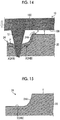
- Fig. 23A illustrates a step 2 formed at an end portion of a recess pattern of the surface of a produced mold 1
- Fig. 23B is an enlarged view of the step 2 in which a part in the circle of Fig. 23A is enlarged.
- Fig. 24 in a case where a duplicate mold 3 (or formed product) is manufactured by using the mold 1 having the step 2 at the end portion of the recess pattern of the mold 1, when the mold 1 is peeled away from the duplicate mold 3 (or formed product), peeling failure such as a difficulty in the peeling due to the step 2 acting as a resistance or breaking of the duplicate mold 3 (or formed product) at the step 2 is likely to occur.
- the present invention has been made taking the above circumstances into consideration, and an object thereof is to provide a production method of a mold, a manufacturing method of a pattern sheet, a production method of an electroform, and a production method of a mold using an electroform, capable of suppressing the generation of a step at an end portion of a recessed pattern.
- a production method of a mold comprising: a preparation process of preparing a plate precursor having a protruding pattern formed of a plurality of protrusions in a pattern presence region on a base, and a thermoplastic resin sheet; an alignment process of determining a position at which the plate precursor is to be pressed against the thermoplastic resin sheet by moving the plate precursor and the thermoplastic resin sheet relative to each other; and a forming process of forming a recessed pattern having an inverted shape of the protruding pattern on the thermoplastic resin sheet by pressing the protrusions of the plate precursor which is heated against the thermoplastic resin sheet at a position where a part of the pattern presence region of the plate precursor excluding the protrusions is separated from a surface of the thermoplastic resin sheet, cooling the plate precursor in a state in which the pressed protrusions and the thermoplastic resin sheet are in contact with each other, and separating the plate precursor from the thermoplastic resin sheet, wherein a depression is formed in advance in
- a vertical sectional shape of the depression is an arcuate shape.
- a vertical sectional shape of the depression is a rectangular shape.
- the depression having an arcuate vertical sectional shape refers to a depression having a side surface which is curved with respect to the bottom surface of the depression.
- the depression having a rectangular vertical sectional shape refers to a depression having a side surface at a right angle to the bottom surface of the depression.
- the pressing surface in the surface of the thermoplastic resin sheet, against which the protrusions forming the protruding pattern of the plate precursor are pressed is flat, and in the forming process, the part of the pattern presence region of the plate precursor excluding the protrusions is stopped before reaching the flat pressing surface.
- the plate precursor is pressed against the thermoplastic resin sheet, a position of the surface of the thermoplastic resin sheet is detected, and the plate precursor is pushed from the position of the surface of the thermoplastic resin sheet by a certain amount.
- a pressure applied to the plate precursor is measured and is compared to a certain pressure value which is set, and the amount of the plate precursor being pushed is determined.
- the protrusion forming the protruding pattern has a frustum portion and a needle portion which is tapered, in a direction away from the base of the plate precursor, and in the forming process, in a case where the plate precursor is pressed against the thermoplastic resin sheet, the frustum portion is brought into contact with the surface of the thermoplastic resin sheet.
- a manufacturing method of a pattern sheet having a protruding pattern comprising: a process of producing a mold using the production method described above; a supplying process of supplying a polymer solution to a recessed pattern of the mold; a drying process of drying the polymer solution to form a polymer sheet; and a polymer sheet peeling process of peeling the polymer sheet from the mold.
- a production method of an electroform having a protruding pattern comprising: a process of producing a mold using the production method described above; an electroforming process of forming a metal body on a recessed pattern of the mold using an electroforming method; and a peeling process of peeling the metal body from the mold.
- a production method of a mold using an electroform comprising: a process of producing an electroform using the production method described above; and a process of, by using the electroform having a protruding pattern, producing a mold which has a recessed pattern which is an inverted shape of the protruding pattern of the electroform and is made of a resin.
- a manufacturing method of a pattern sheet having a protruding pattern comprising: a process of producing a mold using the production method of an electroform described above; a supplying process of supplying a polymer solution to a recessed pattern of the mold; a drying process of drying the polymer solution to form a polymer sheet; and a peeling process of peeling the polymer sheet from the mold.
- the production method of a mold the manufacturing method of a pattern sheet, the production method of an electroform, and the production method of a mold using an electroform of the present invention, the generation of a step at the end portion of the recessed pattern can be suppressed.
- the numerical value range includes the numerical values of the upper limit and the lower limit indicated by "to".
- a pressing surface a surface against which a protruding pattern of a plate precursor is pressed.
- a first embodiment of a production method of a mold of the present invention is applied to a case where the pressing surface is flat, and a case where, when the plate precursor is pressed against the surface of the thermoplastic resin sheet, a part of a pattern presence region of the plate precursor excluding protrusions is stopped before reaching the flat pressing surface.
- the pressing surface X of a thermoplastic resin sheet 20 is flat and flush with a surface 20B, the pressing surface X can also be referred to as the surface 20B.
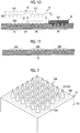
- Figs. 1A to 1E are process diagrams illustrating a procedure of the production method of a mold.
- a large mold 22 having a plurality of recessed patterns 20A is produced using a single plate precursor 10
- Fig. 2 is a perspective view of the plate precursor.
- Fig. 1A illustrates a preparation process of preparing the plate precursor 10.
- the plate precursor 10 is constituted by a base 10C part and a protruding pattern 10A part, and the protruding pattern 10A is formed in a pattern presence region 10D on the base 10C.
- the pattern presence region 10D refers to a region where the protruding pattern 10A is present in the surface of the base 10C of the plate precursor 10 on the side having the protruding pattern 10A.
- the surface of the base 10C on the side having the protruding pattern 10A is formed into a flat surface 10B.
- the flat surface 10B may be a perfectly flat surface or may be a flat surface at first glance.
- the plate precursor 10 has the protruding pattern 10A which is basically the same as a pattern sheet (a so-called formed product) having a protruding pattern to be produced.
- the plate precursor 10 having the protruding pattern 10A is produced, for example, by machining a metal substrate, which is to become the plate precursor 10, using a cutting tool such as a diamond insert bite.
- a metal substrate stainless steel, an aluminum alloy, Ni, or the like may be used.
- the protruding pattern 10A refers to a state in which protrusions 12 protruding in a direction away from the flat surface 10B of the plate precursor 10 are disposed on the flat surface 10B of the plate precursor 10.
- the number of the protrusions 12, the arrangement and positions of the protrusions 12, and the like are not limited.
- the protrusion 12 is constituted by a needle portion 12A which is tapered in the direction away from the flat surface 10B.
- the protrusion 12 is a so-called cone, and the cone includes a pyramid, a circular cone, and the like.
- Figs. 1A and 2 are conceptual views of the plate precursor 10, and Figs. 1A and 2 are different from each other in the number of protrusions 12 constituting the protruding pattern 10A.
- the protrusion 12 preferably has a height of 100 to 2000 ⁇ m from the flat surface 10B of the plate precursor 10 and has a distal end diameter of ⁇ 50 ⁇ m or less.
- the interval between adjacent protrusions 12 is 300 to 2000 ⁇ m.
- the aspect ratio (the height of the protrusion / the width of the bottom surface of the protrusion) of the protrusion 12 is 1 to 5.
- Fig. 1B illustrates a preparation process of preparing a thermoplastic resin sheet.
- the thermoplastic resin sheet 20 as the material of the mold 22 is prepared, and the thermoplastic resin sheet 20 is set, for example, on a table (not illustrated).
- the thermoplastic resin sheet 20 has a thickness of 0.5 to 2.0 mm and a size of 100 mm ⁇ 100 mm to 300 mm ⁇ 300 mm, and has the surface 20B including the pressing surface X against which the protruding pattern 10A of the plate precursor 10 is to be pressed.
- the recessed patterns 20A to be described later are formed on the surface 20B side. It is preferable that the thickness of the thermoplastic resin sheet 20 is equal to or greater than at least the height of the protrusion 12 of the plate precursor 10.
- thermoplastic resin forming the thermoplastic resin sheet 20 is not particularly limited.
- polyethylene terephthalate, polycarbonate, polymethyl methacrylate, polystyrene, polyethylene, a liquid crystal polymer, and polylactic acid may be suitably used.
- the thermoplastic resin sheet 20 means a thermoplastic resin in a state of having a small film thickness and a self-supporting property at room temperature. "Self-supporting property" means that a single body can hold its form without the support of other members.
- Figs. 1C and 1D show an alignment process, a forming process of forming a recessed pattern, and the alignment process and the forming process which are repeatedly performed.
- a small mold 22 having a single plate precursor 10 and a single recessed pattern 20A, there is no need to repeatedly perform the alignment process and the forming process.
- a position (for example, a region A1) at which the plate precursor 10 is pressed against the thermoplastic resin sheet 20 is determined by moving the prepared plate precursor 10 and the thermoplastic resin sheet 20 relative to each other.
- the alignment is performed by providing, for a table that supports the thermoplastic resin sheet 20, an X-axis drive mechanism and a Y-axis drive mechanism which move in directions perpendicular to each other on the horizontal plane.
- thermoplastic resin sheet 20 For accurate alignment, for example, it is preferable to provide alignment marks for alignment on the surface 20B of the thermoplastic resin sheet 20. Furthermore, in order to detect the plate precursor 10, the thermoplastic resin sheet 20, and the alignment marks, it is preferable to provide an imaging device (charge-coupled device (CCD) camera) or the like.
- CCD charge-coupled device
- the heated plate precursor 10 is pressed against the surface 20B side of the thermoplastic resin sheet 20. Accordingly, the protrusions 12 forming the protruding pattern 10A of the plate precursor 10 are pressed against the thermoplastic resin sheet 20.
- the part of the pattern presence region 10D of the plate precursor 10 excluding the protrusions 12 is stopped before reaching the flat pressing surface X of the thermoplastic resin sheet 20. Accordingly, the flat surface 10B of the plate precursor 10 and the flat surface 20B of the thermoplastic resin sheet 20 are separated from each other. Therefore, not the entire pattern presence region 10D of the plate precursor 10 is pushed into the flat surface 20B of the thermoplastic resin sheet 20. Therefore, as indicated by the surrounding circles, the raising of thermoplastic resin sheet 20 at the end portions of the plate precursor 10 can be suppressed.
- the plate precursor 10 is heated to a temperature at which the thermoplastic resin sheet 20 is softened. Heating is performed by a heater (not illustrated). The plate precursor 10 is heated to an appropriate temperature depending on the thermoplastic resin forming the thermoplastic resin sheet 20.
- a Z-axis drive mechanism which moves in the vertical direction is provided for the table (not illustrated) that supports the thermoplastic resin sheet 20 in order to press the protrusions 12 forming the protruding pattern 10A of the plate precursor 10 against the surface 20B side of the thermoplastic resin sheet 20.
- the thermoplastic resin sheet 20 is moved toward the plate precursor 10.
- the plate precursor 10 can also be attached by the Z-axis drive mechanism that moves in the vertical direction. In this case, the plate precursor 10 is moved toward the thermoplastic resin sheet 20.
- the plate precursor 10 While pressing the protrusions 12 of the heated plate precursor 10, the side of the surface 20B of the thermoplastic resin sheet 20 is heated for a certain period of time. Next, in a state in which the pressed protrusions 12 and the thermoplastic resin sheet 20 are brought into contact with each other, the plate precursor 10 is cooled until the thermoplastic resin sheet 20 is cooled to the softening temperature or lower.
- the plate precursor 10 and the thermoplastic resin sheet 20 are separated from each other, thereby forming the recessed pattern 20A having the inverted shape of the protruding pattern 10A on the surface 20B side of the thermoplastic resin sheet 20.
- the separation of the plate precursor 10 from the thermoplastic resin sheet 20 can be performed by the above-described Z-axis drive mechanism.
- the recessed pattern 20A refers to a state in which recesses extending from the surface 20B of the thermoplastic resin sheet 20 toward the other surface are disposed on the surface 20B side of the thermoplastic resin sheet 20.
- the number of recesses, the arrangement of the recesses, the depth of the recesses, and the like are not limited. Since the recessed pattern 20A is the inverted shape of the protruding pattern 10A, the size, number, and arrangement of the recesses of the recessed pattern 20A are basically the same as those of the protrusions 12 pushed into the thermoplastic resin sheet 20.
- a region A2 alignment between the plate precursor 10 and the thermoplastic resin sheet 20 is performed.
- the heated plate precursor 10 is pressed against the surface 20B side of the thermoplastic resin sheet 20.
- the protrusions 12 forming the protruding pattern 10A of the plate precursor 10 are pressed against the surface 20B side of the thermoplastic resin sheet 20.
- the part of the pattern presence region 10D of the plate precursor 10 excluding the protrusions 12 is also stopped before reaching the flat pressing surface X of the thermoplastic resin sheet 20 in the case where the plate precursor 10 is pressed against the surface 20B side of the thermoplastic resin sheet 20.
- the side of the surface 20B of the thermoplastic resin sheet 20 is heated for a certain period of time.
- the plate precursor 10 is cooled until the thermoplastic resin sheet 20 is cooled to the softening temperature or lower.
- the plate precursor 10 and the thermoplastic resin sheet 20 are separated from each other, thereby forming the recessed pattern 20A having the inverted shape of the protruding pattern 10A on the surface 20B of the thermoplastic resin sheet 20.
- the mold 22 is produced from the thermoplastic resin sheet 20.
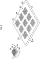
- Fig. 3 is a perspective view of the plate precursor 10 and the mold 22.
- the mold 22 which has 3 ⁇ 3 recessed patterns 20A and is made of a resin is produced using the plate precursor 10 having one protruding pattern 10A.
- a large plate precursor having 3 ⁇ 3 protruding patterns is not produced. Therefore, in this embodiment, the number of operations for producing the plate precursor 10 can be reduced.
- the mold 22 which has 3 ⁇ 3 recessed patterns 20A and is made of a resin is exemplified, the number of recessed patterns 20A is appropriately determined.
- the generation of a step (see Figs. 23A and 23B ) between adjacent recessed patterns 20A can be suppressed. That is, the surface 20B of the mold 22 becomes substantially flat.
- the surface 20B of the mold 22 becomes substantially flat, in a case where a formed product having a protruding pattern is produced using the mold 22, for example, the recessed pattern 20A of the mold 22 can be accurately filled with a polymer solution.
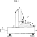
- FIG. 4 is a schematic configuration diagram of an aligning apparatus.
- An aligning apparatus 30 includes a Z-axis drive mechanism 32 which drives the plate precursor 10 in a Z-axis direction, a connection portion 34 connected to the Z-axis drive mechanism 32, a holding portion 36 attached to the connection portion 34, a table 38 which supports the thermoplastic resin sheet 20, an X-axis drive mechanism 40 which drives the table 38 in an X-axis direction, a Y-axis drive mechanism 42 which drives the table 38 in a Y-axis direction, a stand 44, a control system 46, and a laser displacement meter 48.
- the plate precursor 10 is held by the holding portion 36.
- first, alignment between the plate precursor 10 and the thermoplastic resin sheet 20 is performed by driving the X-axis drive mechanism 40 and the Y-axis drive mechanism 42.
- the control system 46 measures the distance between the protruding pattern 10A of the plate precursor 10 and the surface 20B of the thermoplastic resin sheet 20 by using the laser displacement meter 48. By measuring the distance, the position of the surface 20B of the thermoplastic resin sheet 20 can be detected.
- the control system 46 determines the amount of the protruding pattern 10A pushed from the position of the surface 20B of the thermoplastic resin sheet 20.
- the control system 46 drives the Z-axis drive mechanism 32, and the Z-axis drive mechanism 32 moves the plate precursor 10 to the position of the surface 20B of the thermoplastic resin sheet 20 and further pushes the plate precursor 10 toward the thermoplastic resin sheet 20 side by a certain amount (the pushing amount determined).
- a second control method first, alignment between the plate precursor 10 and the thermoplastic resin sheet 20 is performed by driving the X-axis drive mechanism 40 and the Y-axis drive mechanism 42.
- the control system 46 drives the Z-axis drive mechanism 32, and the Z-axis drive mechanism 32 moves the plate precursor 10 to the position of the surface 20B of the thermoplastic resin sheet 20.
- the control system 46 measures the pressure applied to the plate precursor 10 while the plate precursor 10 is moved by the Z-axis drive mechanism 32.
- the pressure measurement method is not particularly limited.
- a load cell may be disposed between the plate precursor 10 and the holding portion 36, and the pressure applied to the plate precursor 10 may be measured by the load cell.
- the load cell is a measuring instrument that can measure a compressive force in the thickness direction thereof.
- the control system 46 compares the measured pressure with a preset pressure. In a case where the measured pressure reaches the preset pressure, the control system 46 determines that the protruding pattern 10A has reached the surface 20B of the thermoplastic resin sheet 20.
- the control system 46 determines the amount of the protruding pattern 10A pushed from the position of the surface 20B of the thermoplastic resin sheet 20.
- the control system 46 drives the Z-axis drive mechanism 32 to push the plate precursor 10 toward the thermoplastic resin sheet 20 by a certain amount (the pushing amount determined).
- a third control method first, alignment between the plate precursor 10 and the thermoplastic resin sheet 20 is performed by the control system 46 by driving the X-axis drive mechanism 40 and the Y-axis drive mechanism 42.
- the control system 46 drives the Z-axis drive mechanism 32, and the Z-axis drive mechanism 32 moves the plate precursor 10 to the position of the surface 20B of the thermoplastic resin sheet 20.
- the control system 46 measures the pressure applied to the plate precursor 10 while the plate precursor 10 is moved by the Z-axis drive mechanism 32.
- the control system 46 compares the measured pressure with a preset pressure.
- the relationship between the pressure applied to the plate precursor 10 and the amount (depth) of the protruding pattern 10A pushed into the thermoplastic resin sheet 20 is previously obtained.
- the control system 46 compares the measured pressure with a preset pressure. In a case where the measured pressure reaches the set pressure, the control system 46 determines that the protruding pattern 10A has reached a desired pushing amount from the surface 20B of the thermoplastic resin sheet 20. In this embodiment, the control system 46 calculates the pushing amount from the previously obtained relationship based on the measured pressure.
- the plate precursor 10 is not pushed into the thermoplastic resin sheet 20. That is, the control system 46 measures a pressure applied to the plate precursor 10, compares the measured pressure with a certain pressure value which is set, and determines the pushing amount of the plate precursor 10 as "0".
- the control system 46 determines the amount of the protruding pattern 10A of the plate precursor 10 pushed into the thermoplastic resin sheet 20 based on the current position of the plate precursor 10.
- the control system 46 drives the Z-axis drive mechanism 32 to push the plate precursor 10 toward the thermoplastic resin sheet 20 by a certain amount (the pushing amount determined).
- the plate precursor 10 having the protrusions 12 with a shape that is different from the shape of the protrusions 12 forming the protruding pattern of the plate precursor 10 illustrated in Fig. 2 and further suppresses the generation of a step will be described.
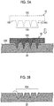
- Fig. 5A is a view illustrating a case of producing the mold 22 using the plate precursor 10 illustrated in Fig. 2 .
- the protrusion 12 included in the protruding pattern 10A of the plate precursor 10 is constituted by a needle portion 12A which is tapered in the direction away from the flat surface 10B.
- thermoplastic resin sheet 20 is raised at the root portion of the protrusion 12.
- steps may be generated on the surface 20B in the region of the recessed pattern 20A of the mold 22.
- the generation of steps can be further suppressed by changing the shape of the protrusions 12 constituting the protruding pattern 10A of the plate precursor 10.
- the step means a protrusion that protrudes from the surface 20B to an extent that the flatness of the surface 20B of the thermoplastic resin sheet 20 is affected. There may be cases where the step affects the productivity in a case where a formed product is manufactured or the precision of the formed product.
- Figs. 6A and 6B illustrate the plate precursor 10 in which the shape of the protrusion 12 is different from that in Fig. 2 .
- the protrusion 12 included in the protruding pattern 10A illustrated in Fig. 6A is constituted by a frustum portion 12B and the tapered needle portion 12A in the direction away from the flat surface 10B.
- the frustum portion 12B includes a square frustum, a circular cone frustum, and the like. Another frustum portion may be included between the frustum portion 12B and the needle portion 12A.
- the protrusion 12 preferably has a height of 100 to 2000 ⁇ m from the flat surface 10B of the plate precursor 10 and has a distal end diameter of ⁇ 50 ⁇ m or less.
- the interval between adjacent protrusions 12 is 300 to 2000 ⁇ m.
- the aspect ratio (the height of the protrusion / the width of the bottom surface of the protrusion) of the protrusion 12 is 1 to 5.
- the ratio of the height of the needle portion 12A to the height of the frustum portion 12B (the height of the needle portion 12A / the height of the frustum portion 12B) is preferably 1 to 10.
- the angle between the side surface of the frustum portion 12B and the flat surface 10B is preferably 10° to 60°.
- the protrusion 12 included in the protruding pattern 10A of the plate precursor 10 illustrated in Fig. 6B is constituted by the frustum portion 12B, a columnar portion 12C, and the needle portion 12A which is tapered, in the direction away from the flat surface 10B.
- the columnar portion 12C means a shape having two opposing parallel bottom surfaces, as represented by a cylinder or a rectangular parallelepiped, in which the areas of the two bottom surfaces are the same.
- the protrusion 12 preferably has a height of 100 to 2000 ⁇ m from the flat surface 10B of the plate precursor 10 and has a distal end diameter of ⁇ 50 ⁇ m or less.
- the interval between adjacent protrusions 12 is 300 to 2000 ⁇ m.
- the aspect ratio (the height of the protrusion / the width of the bottom surface of the protrusion) of the protrusion 12 is 1 to 5.
- the ratio of the total height of the needle portion 12A and the columnar portion 12C to the height of the frustum portion 12B is preferably 1 to 10.
- the ratio of the height of the needle portion 12A to the height of the columnar portion 12C (the height of the needle portion 12A / the height of the columnar portion 12C) is preferably 0.25 to 10.
- the angle between the side surface of the needle portion 12A and the flat surface 10B is preferably 45° to 85°.
- the angle between the side surface of the frustum portion 12B and the flat surface 10B is preferably 10° to 60°.
- Figs. 7A and 7B illustrate states in which the plate precursors 10 illustrated in Figs. 6A and 6B are pressed against the thermoplastic resin sheet 20.
- the plate precursor 10 having the protrusion 12 constituted by the frustum portion 12B, and the tapered needle portion 12A, in the direction away from the flat surface 10B illustrated in Fig. 6A is used.
- the plate precursor 10 is pressed against the thermoplastic resin sheet 20
- the frustum portion 12B of the protrusion 12 into contact with the surface 20B of the thermoplastic resin sheet 20
- the raising of the surface 20B of the thermoplastic resin sheet 20 is suppressed as indicated by the surrounding circle.
- the plate precursor 10 having the protrusion 12 constituted by the frustum portion 12B, the columnar portion 12C, and the tapered needle portion 12A, in the direction away from the flat surface 10B illustrated in Fig. 6B is used.
- the plate precursor 10 is pressed against the thermoplastic resin sheet 20
- by bringing the frustum portion 12B of the protrusion 12 into contact with the surface 20B of the thermoplastic resin sheet 20 raising of the surface 20B of the thermoplastic resin sheet 20 is suppressed as indicated by the surrounding circle.
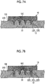
- the second embodiment of the production method of a mold refers to a case where the surface of the thermoplastic resin sheet 20 is the pressing surface X against which the protruding pattern 10A of the plate precursor 10 is pressed and a depression 24 is formed in the pressing surface X in advance.
- the second embodiment refers to a case where the depression 24 is formed in the region where the recessed pattern 20A is formed. That is, the pressing surface X is the region where the recessed pattern 20A is formed in the surface 20B of the thermoplastic resin sheet 20 against which the protrusions 12 forming the protruding pattern 10A of the plate precursor 10 are pressed.
- Fig. 9 is a view corresponding to Fig. 3 , and refers to a case where the depressions 24 are formed in advance in the nine (3 ⁇ 3) pressing surfaces X in which the protruding patterns 20A of the thermoplastic resin sheet 20 are to be formed. Accordingly, the surface of the thermoplastic resin sheet 20 is constituted by the pressing surfaces X in which the depression 24 is formed and a flat outer surface Y in which the depression 24 is not formed.
- the mold 22 which has 3 ⁇ 3 recessed patterns 20A and is made of a resin can be produced using the plate precursor 10 having one protruding pattern 10A.
- Fig. 10 is a sectional view taken along the line 10-10 of Fig. 9 and the region corresponding to the pattern presence region 10D of the plate precursor 10.
- the depression 24 may be the depression 24 having an arc hole shape as illustrated in Fig. 8 .
- the depression 24 having a rectangular hole shape constituted by a bottom surface 24B which is the flat pressing surface X and a side surface 24A is preferable, and the following description will be provided using the depression 24 having a rectangular hole shape as an example.
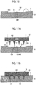
- Figs. 11A to 11C are process diagrams illustrating a procedure of the production method of a mold in which the thermoplastic resin sheet 20 having the depression 24 with a rectangular hole shape formed therein is used.
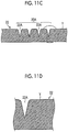
- Fig. 11D is an enlarged view of a mold end portion of the produced mold 22.
- the plate precursor 10 having the protruding pattern 10A on the flat surface 10B, and the thermoplastic resin sheet 20 in which the depression 24 is formed in the pressing surface X in which the recessed pattern 20A is to be formed are prepared (preparation process).
- the position at which the plate precursor 10 is to be pressed against the thermoplastic resin sheet 20 is determined by moving the plate precursor 10 and the thermoplastic resin sheet 20 relative to each other to cause the protruding pattern 10A of the plate precursor 10 to be positioned immediately above the pressing surface X of the thermoplastic resin sheet 20 (alignment process).
- the heated plate precursor 10 is pressed against the thermoplastic resin sheet 20.
- the flat surface 10B of the plate precursor 10 and the outer surface Y of the thermoplastic resin sheet 20 are brought into close contact with each other.
- the plate precursor 10 and the thermoplastic resin sheet 20 are separated from each other, thereby forming the recessed pattern 20A having the inverted shape of the protruding pattern 10A on the thermoplastic resin sheet 20 (forming process).
- the alignment process and the forming process are repeatedly performed for the nine depressions 24.
- the pressing surface X of the thermoplastic resin sheet 20 is raised.
- the depression 24 is formed in advance in the thermoplastic resin sheet 20, even though the pressing surface X of the thermoplastic resin sheet 20 is raised, the raised portion is absorbed by the depression 24, and the generation of a step is suppressed.
- the size (volume) of the depression 24 is appropriately set in consideration of the size of the raised portion of the pressing surface X in a case where the protrusions 12 of the plate precursor 10 are pushed into the thermoplastic resin sheet 20.
- thermoplastic resin sheet 20 by forming the depression 24 in the pressing surface X of the thermoplastic resin sheet 20, the formation of steps caused by pressing the plate precursor 10 against the thermoplastic resin sheet 20 at a position at which the flat surface 10B of the plate precursor 10 and the pressing surface X of the thermoplastic resin sheet 20 are separated from each other is suppressed.
- Fig. 12 is an enlarged view illustrating an end portion surrounded by the circle in the depression 24 having a rectangular hole shape in Fig. 10 .
- the depression 24 having a rectangular vertical sectional shape in which the side surface 24A is provided at a right angle to the bottom surface 24B (the pressing surface X) of the depression is preferable.
- thermoplastic resin sheet 20 in the periphery of the protrusion 12 is melted.
- the melted resin P is pushed away by the pressing force of the protrusion 12 and flows into the depression 24.
- the depression 24 is rectangular, the melted resin P flowing into the depression 24 is blocked by the side surface 24A of the depression 24. This makes it difficult for the melted resin P to flow to the outer surface Y of the thermoplastic resin sheet 20. Therefore, the formation of steps at the mold end portions of the produced mold 22 can be further suppressed.
- the depression 24 having the side surface 24A which is curved with respect to the bottom surface 24B (the pressing surface X) (having an arcuate vertical sectional shape) is preferable.
- thermoplastic resin sheet 20 is plastically deformed and the pressing surface X is raised.
- the pressing surface X is raised along the curved side surface 24A, and raised portions Q which are raised throughout the entire space between the protrusions 12 and the depression 24 are easily formed. Accordingly, it is easy to effectively use the space of the depression 24 which absorbs the raised portions of the thermoplastic resin sheet 20, and it becomes difficult for the raised portion Q to reach the outer surface Y of the thermoplastic resin sheet 20. Therefore, the formation of steps at the end portions of the recessed pattern 20A of the produced mold 22 can be further suppressed.
- the raising force is more likely to be cut off by the side surface 24A at a right angle than the arcuate shape, and the raised portions Q having a mountain shape are easily formed in the space between the protrusions 12 and the depression 24. Accordingly, it is difficult to effectively use the space of the depression 24 that absorbs the raised portion of the thermoplastic resin sheet 20, so that there may be cases where the raised portion Q reaches the outer surface Y of the thermoplastic resin sheet 20. Therefore, there may be cases where steps are formed at the end portions of the recessed pattern 20A of the produced mold 22.
- the aligning apparatus 30 and the control method described in the first embodiment can also be applied to the second embodiment. Furthermore, it is preferable that as in the first embodiment, the plate precursor 10 having the protrusions 12 having the shapes described with reference to Figs. 6A and 6B is used in the second embodiment.
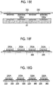
- Figs. 18A to 18G are process diagrams illustrating a procedure of the manufacturing method of a pattern sheet using the mold 22.
- Fig. 18A illustrates a state in which the mold 22 is prepared.
- the mold 22 is produced by the production method of a mold described above, and the recessed patterns 20A are formed on the surface 20B of the mold 22.
- Fig. 18B illustrates a supplying process of supplying a polymer solution to the recessed patterns 20A of the mold 22.
- a polymer solution 200 is prepared.
- a material of the resin polymer used for the polymer solution 200 it is preferable to use a biocompatible resin.
- a biocompatible resin As such resins, sugars such as glucose, maltose, pullulan, sodium chondroitin sulfate, sodium hyaluronate, hydroxyethyl starch, and hydroxypropyl cellulose, proteins such as gelatin, and biodegradable polymers such as polylactic acid and a lactic acid-glycolic acid copolymer are preferably used.
- gelatin-based materials have adhesion to many base materials and have a strong gel strength in a case of being used as a gelating material
- the gelatin-based materials can be brought into close contact with a base material in a peeling process, which will be described later, and a polymer sheet can be peeled away from the mold 22 using the base material, so that the gelatin-based materials can be suitably used.
- a drug may be contained in the polymer solution 200.
- the drug to be contained in the polymer solution 200 is not particularly limited as long as the drug is a substance having a physiological activity.
- the drug is preferably selected from peptides, proteins, nucleic acids, polysaccharides, vaccines, pharmaceutical compounds, or cosmetic ingredients.
- the pharmaceutical compound belongs to a water-soluble low molecular weight compound.
- the low molecular weight compound is a compound having a molecular weight range of several hundreds to several thousands.
- the concentration varies depending on the material, it is preferable that the concentration is set so that the resin polymer is contained at 10 to 50 mass% in the polymer solution 200 which does not contain the drug.
- the solvent used for dissolution may be warm water or may be volatile, and methyl ethyl ketone, alcohol, or the like may be used.
- the polymer concentration of the polymer solution 200 containing the drug is preferably in a range of 0 to 40 mass%.
- a water-soluble polymer such as gelatin
- a water-soluble powder may be dissolved in water and the drug may be added after the dissolution. Otherwise, a powder of a water-soluble polymer may be dissolved in a liquid in which the drug is dissolved.
- heating may be performed for dissolution.
- the temperature can be appropriately selected depending on the kind of the polymer material, and it is preferable that heating is performed at a temperature of about 60°C or lower.
- the viscosity of the solution of the polymer resin is preferably 100 Pa ⁇ s or less, and more preferably 10 Pa ⁇ s or less.
- the viscosity is preferably 2000 Pa ⁇ s or less, and more preferably 1000 Pa ⁇ s or less.
- injecting the solution into a needle-like recess of a mold is facilitated.
- the viscosity of the solution of the polymer resin can be measured with a capillary viscometer, a falling ball viscometer, a rotational viscometer, or a vibrational viscometer.
- the polymer solution 200 is supplied to the mold 22 such that the recessed patterns 20A are filled with the polymer solution 200. That is, the recesses constituting the recessed patterns 20A are filled with the polymer solution 200.
- a method for filling the recessed patterns 20A with the polymer solution 200 As a method for filling the recessed patterns 20A with the polymer solution 200, a method of performing filling using a spin coater, a method of performing filling by moving a squeegee, a method of performing filling while moving a slit nozzle, a method of filling the recesses of the recessed patterns 20A using a dispenser, or the like may be employed.
- the polymer solution 200 is supplied to the recessed patterns 20A while moving the slit nozzle and the mold 22 relative to each other.
- the surface of the mold 22 preferably has flatness.
- the supplying process is preferably performed under an environment at reduced pressure.
- the environment at reduced pressure means a state at or below atmospheric pressure.
- the polymer solution 200 can be supplied to the distal end of the recessed pattern 20A while the air is released from the recess under the environment at reduced pressure. This is particularly effective in a case where the mold 22 is a gas permeable material.
- the mold 22 supplied with the polymer solution 200 is placed in a pressure vessel. After heating the inside of the pressure vessel to 40°C using a heating jacket, compressed air is injected into the pressure vessel from a compressor. The air in the recess is removed by holding the inside of the pressure vessel at a pressure of 0.5 MPa for 5 minutes and applying a pressure to the mold, thereby enabling the polymer solution 200 to be supplied to the distal end of the recessed pattern 20A of the mold 22.
- Fig. 18C illustrates a drying process of drying the polymer solution 200 to form the polymer sheet 210.
- the polymer solution 200 supplied to the mold 22 can be dried by blowing air thereto.
- Drying is divided into, for example, four zones, and by setting conditions including (1) set dry at 15°C (low humidity, wind speed 4 m/sec), (2) light wind drying at 35°C (low humidity, wind speed 8 m/sec), (3) strong wind drying at 50°C (wind speed 12 m/sec), and (4) strong wind drying at 30°C (wind speed 20 m/sec), efficient drying can be performed.
- the applied polymer solution 200 is dried, or the polymer solution 200 is gelated and then dried to solidify, thereby obtaining the polymer sheet 210.
- the shape thereof can be reduced and a property of peeling the polymer solution 200 from the mold 22 can be enhanced.
- the polymer solution 200 can be gelated by flowing cold air at a low humidity. In order to completely gelate the polymer solution 200, cold air at 10 to 15 [°C] is blown for a longer period of time than in the above case, and thereafter air is blown in the same manner as above.
- the polymer sheet 210 is reduced in size compared to the state in a case where the polymer solution 200 is injected. Particularly, in a case where gelation is performed, the polymer sheet 210 is significantly reduced in size. Accordingly, peeling of the polymer sheet 210 from the mold 22 described later is facilitated.
- the polymer sheet 210 means a state after a desired drying treatment is applied to the polymer solution 200.
- the moisture content of the polymer sheet 210 and the like are appropriately set.
- Figs. 18D and 18E illustrate a polymer sheet peeling process of peeling the polymer sheet 210 from the mold 22.
- a sheet-like base material 300 having a pressure sensitive adhesive layer formed thereon is attached to the surface of the polymer sheet 210 opposite to the mold 22.
- the surface of the base material 300 may be subjected to a surface activation treatment so as to be bonded.
- the polymer solution may be applied thereto from above the base material 300 to bury the base material 300 therein.
- a material of the sheet-like base material 300 for example, polyethylene terephthalate (PET), polypropylene (PP), polycarbonate (PC), or polyethylene (PE), may be used.
- the base material 300 and the polymer sheet 210 are simultaneously peeled away.
- a sucker (not illustrated) is placed on the surface of the base material 300 opposite to the bonding surface of the polymer sheet 210, and is pulled up vertically while sucking the base material 300 with air.
- the polymer sheet 210 is peeled away from the mold 22, thereby forming a pattern sheet 220 having a protruding pattern 220A.
- the material forming the mold 22 is made of a material which can be very easily peeled away. Furthermore, by using a highly elastic and soft material as the material forming the mold 22, stress applied to the protruding pattern 220A of the pattern sheet 220 during peeling can be relieved.
- the protruding pattern 220A of the pattern sheet 220 has the inverted shape of the recessed pattern 20A of the mold 22.
- the pattern sheet 220 is basically the same as the polymer sheet 210 peeled away from the mold 22.
- Figs. 18F and 18G illustrate a cutting process of cutting the pattern sheet 220 into the individual pattern sheets 220.
- the pattern sheet 220 having the protruding pattern 220A and the base material 300 peeled away from the mold 22 are set in a cutting device (not illustrated).
- the positions to cut the pattern sheet 220 are determined. Basically, the cutting position is determined for each protruding pattern 220A.
- the pattern sheet 220 is cut into a plurality of the individual pattern sheets 220.
- the example in which the pattern sheet 220 and the base material 300 are simultaneously cut is described, but the present invention is not limited thereto.
- the base material 300 may be peeled away from the pattern sheet 220 and the base material 300 peeled away from the mold 22, and the pattern sheet 220 may be cut into the individual pattern sheets 220.
- the present invention is not limited thereto.
- a polymer sheet can be formed by filling the recessed pattern 20A with the polymer solution 200 containing the drug, drying the polymer solution 200, filling the recessed pattern 20A with the polymer solution 200 which does not contain a drug, and drying the polymer solution 200.
- the number of times the polymer solution 200 is supplied and the presence or absence of the drug in the polymer solution 200 can be appropriately changed.
- Fig. 19 is a perspective view of the individual pattern sheet 220.
- the individual pattern sheet 220 has the protruding pattern 220A on one surface.
- the pattern sheet 220 has the base material 300 on the surface opposite to the surface on which the protruding pattern 220A is formed.
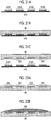
- FIGs. 20A to 20C are process diagrams illustrating a procedure of the production method of an electroform using the mold 22.
- Fig. 20A illustrates a state in which the mold 22 is prepared.
- the mold 22 is produced by the above-described production method of the mold 22, and the recessed pattern 20A is formed on the surface 20B of the mold 22.
- Fig. 20B is a process diagram illustrating an electroforming process in which metal is buried in the recessed pattern 20A of the mold 22 by an electroforming method.
- a conduction treatment is performed on the mold 22.
- Metal for example, nickel
- the mold 22 subjected to the conduction treatment is held at a cathode.
- Metal pellets are held in a metallic case as an anode.
- the cathode holding the mold 22 and the anode holding the metal pellets are immersed in an electroforming liquid to cause electricity to flow.
- the metal is buried in the recessed pattern 20A of the mold 22 by the electroforming method, thereby forming a metal body 400.
- the electroforming method refers to a method of depositing metal on the surface of a mold by an electroplating method.
- Fig. 20C is a process diagram illustrating a peeling process of peeling the metal body 400 from the mold 22.
- the metal body 400 is peeled away from the mold 22, thereby producing an electroform 410 having a protruding pattern 410A. Peeling means the separation of the metal body 400 from the mold 22.
- the protruding pattern 410A has the inverted shape of the recessed pattern 20A of the mold 22.
- the electroform 410 is basically the same as the metal body 400 peeled away from the mold 22.
- the mold 22 is produced using the plate precursor 10 illustrated in Fig. 2
- the electroform 410 is produced using the mold 22 illustrated in Figs. 20A to 20C . Therefore, the electroform 410 having a larger area than the plate precursor 10 can be obtained.
- the electroform 410 has the same function as the plate precursor 10 in terms of being used as a plate precursor in a case where the mold 22 is produced, and has a larger area than the plate precursor 10. That is, since a plate precursor having a large area can be obtained by an electroforming method other than machining such as grinding, the costs for producing the plate precursor having a large area can be reduced.
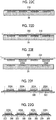
- FIGs. 21A to 21C are process diagrams illustrating a procedure of the production method of the mold 26 using the electroform 410.
- Fig. 21A illustrates a state in which the electroform 410 is prepared.
- the electroform 410 is produced by the above-described production method of the electroform 410.
- the electroform 410 has the protruding pattern 410A on one side.
- Figs. 21B and 21C are process diagrams illustrating a process of producing a mold 26 which has a recessed pattern 26A which has the inverted shape of the protruding pattern 410A of the electroform 410 and is made of a resin, by using the electroform 410 having the protruding pattern 410A.
- the recessed pattern 26A refers to a state in which recesses extending from one surface of the mold 26 toward the other surface are disposed on one surface of the mold 26.
- the number of recesses, the positions of the disposed recesses, and the like are not limited.
- the mold 26 having the recessed pattern 26A can be produced by the following first to third methods.
- An ultraviolet curable resin which is cured by being irradiated with ultraviolet rays is prepared.
- the protruding pattern 410A of the electroform 410 is pressed against the ultraviolet curable resin.
- the ultraviolet curable resin is irradiated with ultraviolet rays such that the ultraviolet curable resin is cured.
- the electroform 410 is peeled away from the ultraviolet curable resin which is cured.
- the mold 26 having the recessed pattern 26A which has the inverted shape of the protruding pattern 410A of the electroform 410 and is made of the resin can be produced.
- thermoplastic resin sheet as the material of the mold 26 is prepared.
- the electroform 410 having the protruding pattern 410A is heated.
- the protruding pattern 410A of the heated electroform 410 is pressed against the surface of the thermoplastic resin sheet. Since the surface of the thermoplastic resin is softened, the protruding pattern 410A is transferred onto the thermoplastic resin sheet.
- thermoplastic resin sheet In the state in which the electroform 410 is pressed against the thermoplastic resin sheet, the thermoplastic resin sheet and the electroform 410 are cooled. The thermoplastic resin sheet is cured by cooling the electroform 410. Thereafter, the electroform 410 is peeled away from the thermoplastic resin sheet to which the protruding pattern 410A has been transferred.
- the mold 26 having the recessed pattern 26A which has the inverted shape of the protruding pattern 410A of the electroform 410 and is made of the resin can be produced.
- a silicone resin is prepared by adding a hardener to PDMS (polydimethylsiloxane, for example, SYLGARD 184 manufactured by Dow Corning Corporation, SYLGARD: trademark).
- PDMS polydimethylsiloxane
- SYLGARD 184 manufactured by Dow Corning Corporation, SYLGARD: trademark.
- the protruding pattern 410A of the electroform 410 is pressed against the silicone resin.
- the silicone resin is heated and cured at 100°C.
- the electroform 410 is peeled away from the cured silicone resin.
- the mold 26 having the recessed pattern 26A which has the inverted shape of the protruding pattern 410A of the electroform 410 and is made of the resin can be produced.
- the size of each recess of the recessed pattern 26A is substantially the same as the size of the protrusion of the protruding pattern 410A.
- the method of producing the mold 26 is not limited to the first to third methods.
- Figs. 22A to 22G are process diagrams illustrating a procedure of the manufacturing method of the pattern sheet 220 using the mold 26.
- the process diagrams illustrating the procedure of the manufacturing method of the pattern sheet in Figs. 18A to 18G and the process diagrams illustrating the procedure of the manufacturing method of the pattern sheet in Figs. 22A to 22G are basically the same except for the difference between the mold 22 and the mold 26. Therefore, like configurations which are similar to those of the process diagrams illustrated in Figs. 18A to 18G are denoted by like reference numerals, and the description thereof may be omitted in some cases.
- Fig. 22A illustrates a state in which the mold 26 is prepared. As illustrated in Figs. 21A to 21C described above, the mold 26 is produced using the electroform 410. The mold 26 has the recessed pattern 26A on one side.
- Fig. 22B illustrates a supplying process of supplying the polymer solution 200 to the recessed pattern 26A of the mold 26.
- the polymer solution 200 is basically the same as the polymer solution 200 described with reference to Figs. 18A to 18G .
- the polymer solution 200 is supplied to the mold 26 such that the recessed pattern 26A is filled with the polymer solution 200. That is, the recesses constituting the recessed pattern 26A are filled with the polymer solution 200.
- the filling methods described with reference to Figs. 18A to 18G may be applied.
- Fig. 22C illustrates a drying process of drying the polymer solution 200 to form the polymer sheet 210.
- the polymer solution 200 supplied to the mold 26 can be dried by blowing air thereto.
- the drying method, conditions, and the like described with reference to Figs. 18A to 18G can be applied.
- Figs. 22D and 22E illustrate a polymer sheet peeling process of peeling the polymer sheet 210 from the mold 26.
- the sheet-like base material 300 having a pressure sensitive adhesive layer formed thereon is attached to the surface of the polymer sheet 210 opposite to the mold 26.
- the base material 300 and the polymer sheet 210 are simultaneously peeled away.
- a sucker (not illustrated) is placed on the surface of the base material 300 opposite to the bonding surface of the polymer sheet 210, and is pulled up vertically while sucking the base material 300 with air.
- the polymer sheet 210 is peeled away from the mold 26, thereby forming the pattern sheet 220 having the protruding pattern 220A.
- the material forming the mold 26 is made of a material which can be very easily peeled away. Furthermore, by using a highly elastic and soft material as the material forming the mold 26, stress applied to the protruding pattern 220A of the pattern sheet 220 during peeling can be relieved.
- the protruding pattern 220A of the pattern sheet 220 has the inverted shape of the recessed pattern 26A of the mold 26.
- the pattern sheet 220 is basically the same as the polymer sheet 210 peeled away from the mold 26.
- Figs. 22F and 22G illustrate a cutting process of cutting the pattern sheet 220 into the individual pattern sheets 220.
- the pattern sheet 220 having the protruding pattern 220A and the base material 300 peeled away from the mold 26 are set in a cutting device (not illustrated).
- the positions to cut the pattern sheet 220 are determined. Basically, the cutting position is determined for each protruding pattern 220A.
- the pattern sheet 220 is cut into a plurality of the individual pattern sheets 220.
- the example in which the pattern sheet 220 and the base material 300 are simultaneously cut is described, but the present invention is not limited thereto.
- the base material 300 may be peeled away from the pattern sheet 220 and the base material 300 peeled away from the mold 26, and the pattern sheet 220 may be cut into the individual pattern sheets 220.
- the present invention is not limited thereto.
- a polymer sheet can be formed by filling the recessed pattern 20A with the polymer solution 200 containing the drug, drying the polymer solution 200, filling the recessed pattern 20A with the polymer solution 200 which does not contain a drug, and drying the polymer solution 200.
- the number of times the polymer solution 200 is supplied and the presence or absence of the drug in the polymer solution 200 can be appropriately changed.
- the generation of a step between recessed patterns can be suppressed, the number of operations of producing the plate precursor can be reduced, and the productivity can be improved.
Landscapes
- Engineering & Computer Science (AREA)
- Health & Medical Sciences (AREA)
- Mechanical Engineering (AREA)
- Veterinary Medicine (AREA)
- Anesthesiology (AREA)
- Biomedical Technology (AREA)
- Heart & Thoracic Surgery (AREA)
- Hematology (AREA)
- Life Sciences & Earth Sciences (AREA)
- Animal Behavior & Ethology (AREA)
- General Health & Medical Sciences (AREA)
- Public Health (AREA)
- Medical Informatics (AREA)
- Dermatology (AREA)
- Manufacturing & Machinery (AREA)
- Chemical & Material Sciences (AREA)
- Microelectronics & Electronic Packaging (AREA)
- Chemical Kinetics & Catalysis (AREA)
- Electrochemistry (AREA)
- Materials Engineering (AREA)
- Metallurgy (AREA)
- Organic Chemistry (AREA)
- Shaping Of Tube Ends By Bending Or Straightening (AREA)
- Moulds For Moulding Plastics Or The Like (AREA)
- Micromachines (AREA)
Claims (11)
- Procédé de production d'un moule (22), comprenant :un processus de préparation pour préparer un précurseur de plaque (10) présentant un motif saillant (10A) formé d'une pluralité de protubérances (12) dans une région de présence de motif sur une base, et une feuille en résine thermoplastique (20) ;un processus d'alignement pour déterminer une position sur laquelle le précurseur de plaque doit être pressé contre la feuille en résine thermoplastique en déplaçant le précurseur de plaque et la feuille en résine thermoplastique l'un par rapport à l'autre ;un processus de formage pour former un motif en retrait présentant une forme inversée du motif saillant (10A) sur la feuille en résine thermoplastique (20) en pressant les protubérances (12) du précurseur de plaque (10), lequel est chauffé contre la feuille en résine thermoplastique (20) en une position où une partie de la région de présence de motif du précurseur de plaque (10) excluant les protubérances (12) est séparée d'une surface de la feuille en résine thermoplastique (20), en refroidissant le précurseur de plaque (10) dans un état où les protubérances pressées (12) et la feuille en résine thermoplastique (20) sont en contact entre elles, et en séparant le précurseur de plaque (10) de la feuille en résine thermoplastique (20),caractérisé en ce queun creux (24) est formé à l'avance dans une surface de pressage (X) dans la surface de la feuille en résine thermoplastique (20), contre laquelle les protubérances (12) formant le motif saillant (10A) du précurseur de plaque (10) sont pressées.
- Procédé de production d'un moule (22) selon la revendication 1,
dans lequel une épaisseur de la feuille en résine thermoplastique (20) est supérieure ou égale à une hauteur des protubérances (12) du précurseur de plaque (10). - Procédé de production d'un moule (22) selon la revendication 1 ou 2,
dans lequel lors du processus de formage, dans un cas où une température de chauffage du précurseur de plaque (10) est inférieure ou égale à un point de fusion de la feuille en résine thermoplastique (20), une forme en coupe verticale du creux (24) est une forme arquée. - Procédé de production d'un moule (22) selon la revendication 1 ou 2,
dans lequel lors du processus de formage, dans un cas où une température de chauffage du précurseur de plaque (10) est supérieure ou égale à un point de fusion de la feuille en résine thermoplastique (20), une forme en coupe verticale du creux (24) est une forme rectangulaire. - Procédé de production d'un moule (22) selon l'une quelconque des revendications 1 à 4,
dans lequel une surface de pressage dans la surface de la feuille en résine thermoplastique (20), contre laquelle les protubérances (12) formant le motif saillant du précurseur de plaque (10) sont pressées, est plate, et lors du processus de formage, la partie de la région de présence de motif du précurseur de plaque (10) excluant les protubérances (12) est arrêtée avant d'atteindre la surface de pressage plate (X, 24B). - Procédé de production d'un moule (22) selon l'une quelconque des revendications 1 à 5,
dans lequel dans un cas où le précurseur de plaque (10) est pressé contre la feuille en résine thermoplastique (20), une position de la surface de la feuille en résine thermoplastique (20) est détectée, et le précurseur de plaque (10) est poussé de la position de la surface de la feuille en résine thermoplastique (20) à raison d'une certaine quantité, ou
dans lequel dans un cas où le précurseur de plaque (10) est pressé contre la feuille en résine thermoplastique (20), une pression exercée sur le précurseur de plaque est mesurée et comparée à une certaine valeur de pression, laquelle est réglée, et la quantité du précurseur de plaque (10) étant poussé est déterminée. - Procédé de production d'un moule (22) selon l'une quelconque des revendications 1 à 5,
dans lequel la protubérance (12) présente une portion tronconique et une portion d'aiguille, laquelle présente un amincissement progressif, dans une direction s'éloignant de la base du précurseur de plaque, et lors du processus de formage, dans un cas où le précurseur de plaque est pressé contre la feuille en résine thermoplastique, la portion tronconique est amenée en contact avec la surface de la feuille en résine thermoplastique. - Procédé de fabrication d'une feuille à motif (220) présentant un motif saillant (220A), comprenant :un processus de production d'un moule (22), à l'aide du procédé de production selon l'une quelconque des revendications 1 à 7 ;un processus d'alimentation pour alimenter une solution polymère (200) vers un motif en retrait (20A) du moule (22) ;un processus de séchage pour sécher la solution polymère (200), afin de former une feuille polymère (210), etun processus de décollage de la feuille polymère pour décoller la feuille polymère (210) du moule (22).
- Procédé de production d'une électroforme (410) présentant un motif saillant (410A), comprenant :un processus de production d'un moule (22), à l'aide du procédé de production selon l'une quelconque des revendications 1 à 7 ;un processus d'électroformage pour former un corps métallique (400) sur un motif en retrait du moule (22) à l'aide d'un procédé d'électroformage, etun processus de décollage pour décoller le corps métallique (400) du moule (22).
- Procédé de production d'un moule (26) à l'aide d'une électroforme (410), comprenant :un processus de production d'une électroforme (410) à l'aide du procédé de production selon la revendication 9, etun processus pour produire, à l'aide de l'électroforme (410) présentant le motif saillant (410A), un moule (26), lequel présente un motif en retrait (26A) qui présente une forme inversée du motif saillant de l'électroforme (410), et est fabriqué dans une résine.
- Procédé de fabrication d'une feuille à motif présentant un motif saillant, comprenant
un processus de production d'un moule (26), lequel est fabriqué dans une résine, à l'aide du procédé de production selon la revendication 10 ;
un processus d'alimentation pour alimenter une solution polymère (200) vers le motif en retrait (26A) du moule (26) ;
un processus de séchage pour sécher la solution polymère (200) pour former une feuille polymère (210), et
un processus de décollage de la feuille polymère (210) hors du moule (26) fabriqué dans une résine.
Applications Claiming Priority (3)
| Application Number | Priority Date | Filing Date | Title |
|---|---|---|---|
| JP2015193480 | 2015-09-30 | ||
| JP2016097825 | 2016-05-16 | ||
| PCT/JP2016/076340 WO2017056894A1 (fr) | 2015-09-30 | 2016-09-07 | Procédé de fabrication de moule, procédé de production de feuille à motif, procédé de fabrication de moule électroformé, et procédé de fabrication de moule à l'aide d'un moule électroformé |
Publications (3)
| Publication Number | Publication Date |
|---|---|
| EP3357862A1 EP3357862A1 (fr) | 2018-08-08 |
| EP3357862A4 EP3357862A4 (fr) | 2019-03-06 |
| EP3357862B1 true EP3357862B1 (fr) | 2020-03-04 |
Family
ID=58423314
Family Applications (1)
| Application Number | Title | Priority Date | Filing Date |
|---|---|---|---|
| EP16851068.3A Active EP3357862B1 (fr) | 2015-09-30 | 2016-09-07 | Procédé de fabrication de moule, procédé de production de feuille à motif, procédé de fabrication de moule électroformé, et procédé de fabrication de moule à l'aide d'un moule électroformé |
Country Status (6)
| Country | Link |
|---|---|
| US (1) | US11007678B2 (fr) |
| EP (1) | EP3357862B1 (fr) |
| JP (1) | JP6495465B2 (fr) |
| KR (1) | KR102074603B1 (fr) |
| CN (1) | CN107922183B (fr) |
| WO (1) | WO2017056894A1 (fr) |
Families Citing this family (11)
| Publication number | Priority date | Publication date | Assignee | Title |
|---|---|---|---|---|
| US11504512B2 (en) * | 2017-05-10 | 2022-11-22 | Chee Yen Lim | Method of fabricating microneedle patches |
| WO2019188796A1 (fr) * | 2018-03-27 | 2019-10-03 | 富士フイルム株式会社 | Procédé de fabrication d'un moule ayant un profil de socle concave et procédé de fabrication d'une feuille à motif |
| EP3777954A4 (fr) * | 2018-03-30 | 2021-05-26 | FUJIFILM Corporation | Moule de fabrication de feuille d'absorption transdermique, et dispositif et procédé de fabrication de feuille d'absorption transdermique ayant une protubérance de type aiguille |
| CN111801135B (zh) * | 2018-03-30 | 2023-06-27 | 富士胶片株式会社 | 微针阵列的制造方法 |
| WO2019225288A1 (fr) * | 2018-05-25 | 2019-11-28 | 富士フイルム株式会社 | Procédé de fabrication d'un moule ayant un motif renfoncé dans une partie en gradin renfoncée, et procédé de production de feuille à motifs |
| JP6823009B2 (ja) * | 2018-05-30 | 2021-01-27 | 花王株式会社 | 微細中空突起具の製造方法、及び微細中空突起具 |
| JP6985233B2 (ja) * | 2018-10-15 | 2021-12-22 | 富士フイルム株式会社 | 針状突起を有する原版の製造方法、及びマイクロニードルアレイの製造方法 |
| JP7038679B2 (ja) * | 2019-03-05 | 2022-03-18 | 富士フイルム株式会社 | 熱可塑性樹脂原版の作製方法、金型の作製方法、モールドの作製方法及びパターンシートの製造方法 |
| DE102020104306A1 (de) | 2020-02-19 | 2021-08-19 | Lts Lohmann Therapie-Systeme Ag | Formelement zur Herstellung von Mikrostrukturen |
| CN114497911B (zh) * | 2022-01-25 | 2023-04-25 | 厦门海辰储能科技股份有限公司 | 极片以及锂离子电池 |
| KR102705460B1 (ko) * | 2024-02-02 | 2024-09-11 | 주식회사에이치앤디테크 | 마이크로 니들 몰드 제조용 금형 및 이를 이용하여 제조된 마이크로 니들 몰드 |
Family Cites Families (15)
| Publication number | Priority date | Publication date | Assignee | Title |
|---|---|---|---|---|
| JP3716504B2 (ja) * | 1996-08-05 | 2005-11-16 | 富士ゼロックス株式会社 | 微小構造体の製造方法および装置 |
| US7150844B2 (en) * | 2003-10-16 | 2006-12-19 | Seagate Technology Llc | Dry passivation process for stamper/imprinter family making for patterned recording media |
| WO2005087305A1 (fr) | 2004-03-12 | 2005-09-22 | Agency For Science, Technology And Research | Procedes et moules s'utilisant dans la fabrication de micro-aiguilles a orifice lateral |
| WO2006131153A1 (fr) * | 2005-06-10 | 2006-12-14 | Obducat Ab | Reproduction de motif a tampon intermediaire |
| JP4736821B2 (ja) * | 2006-01-24 | 2011-07-27 | 株式会社日立製作所 | パターン形成方法およびパターン形成装置 |
| JP4936519B2 (ja) * | 2006-08-18 | 2012-05-23 | 公立大学法人大阪府立大学 | ナノ構造及びマイクロ構造を有する構造体の成形用モールドの製造方法及び該モールドを用いる該構造体の製造方法 |
| US20090318833A1 (en) * | 2006-09-18 | 2009-12-24 | Agency For Science Technology And Research | Needle Structures and Methods for Fabricating Needle Structures |
| JP2008142183A (ja) * | 2006-12-07 | 2008-06-26 | Fujifilm Corp | マイクロニードルシート及びその製造方法 |
| JP2010263124A (ja) * | 2009-05-08 | 2010-11-18 | Sumitomo Electric Ind Ltd | Iii−v族半導体光デバイスの製造方法 |
| JP5542404B2 (ja) * | 2009-10-08 | 2014-07-09 | 東レエンジニアリング株式会社 | マイクロニードルスタンパーの製造方法 |
| JP5558772B2 (ja) * | 2009-10-08 | 2014-07-23 | 東レエンジニアリング株式会社 | マイクロニードルシートのスタンパー及びその製造方法とそれを用いたマイクロニードルの製造方法 |
| JP5433370B2 (ja) | 2009-10-16 | 2014-03-05 | 東芝機械株式会社 | 型の製造方法 |
| JP5699461B2 (ja) * | 2010-07-02 | 2015-04-08 | 住友電気工業株式会社 | ナノインプリント用モールド |
| JP2012055343A (ja) * | 2010-09-03 | 2012-03-22 | Toray Eng Co Ltd | マイクロニードルシート及びその製造方法 |
| JP6034398B2 (ja) * | 2012-11-13 | 2016-11-30 | 富士フイルム株式会社 | モールド成形体及び経皮吸収シートの製造方法 |
-
2016
- 2016-09-07 EP EP16851068.3A patent/EP3357862B1/fr active Active
- 2016-09-07 CN CN201680050229.3A patent/CN107922183B/zh active Active
- 2016-09-07 JP JP2017543062A patent/JP6495465B2/ja not_active Expired - Fee Related
- 2016-09-07 KR KR1020187006454A patent/KR102074603B1/ko active Active
- 2016-09-07 WO PCT/JP2016/076340 patent/WO2017056894A1/fr not_active Ceased
-
2018
- 2018-03-23 US US15/933,573 patent/US11007678B2/en active Active
Non-Patent Citations (1)
| Title |
|---|
| None * |
Also Published As
| Publication number | Publication date |
|---|---|
| US11007678B2 (en) | 2021-05-18 |
| JP6495465B2 (ja) | 2019-04-03 |
| CN107922183B (zh) | 2022-09-13 |
| KR102074603B1 (ko) | 2020-02-06 |
| EP3357862A1 (fr) | 2018-08-08 |
| WO2017056894A1 (fr) | 2017-04-06 |
| EP3357862A4 (fr) | 2019-03-06 |
| US20180215078A1 (en) | 2018-08-02 |
| JPWO2017056894A1 (ja) | 2018-06-21 |
| KR20180039103A (ko) | 2018-04-17 |
| CN107922183A (zh) | 2018-04-17 |
Similar Documents
| Publication | Publication Date | Title |
|---|---|---|
| EP3357862B1 (fr) | Procédé de fabrication de moule, procédé de production de feuille à motif, procédé de fabrication de moule électroformé, et procédé de fabrication de moule à l'aide d'un moule électroformé | |
| US11772305B2 (en) | Production method of mold having recessed pattern in recessed step portion | |
| US10814527B2 (en) | Method of producing transdermal absorption sheet | |
| US20180250851A1 (en) | Manufacturing method of pattern sheet | |
| EP3243624B1 (fr) | Procédé de production d'un moule, procédé de fabrication de feuille de motif, procédé de production d'électroforme, procédé de production de moule utilisant l'électroformage et original | |
| US10441532B2 (en) | Method of producing transdermal absorption sheet | |
| US10814118B2 (en) | Transdermal absorption sheet | |
| EP3153290B1 (fr) | Procédé de fabrication de moule et procédé de fabrication de feuille de motif | |
| EP3266493B1 (fr) | Feuille d'absorption transdermique et procédé de fabrication correspondant | |
| US20180243952A1 (en) | Manufacturing method of sheet having needle-like protrusions | |
| EP3153291B1 (fr) | Procédé de fabrication de moule et procédé de fabrication de feuille de motif | |
| CN110251824B (zh) | 一种用于透皮给药的柔性微针贴片及其制作方法 | |
| CN117159901A (zh) | 一种微针贴片的制备方法及成型模具、对位贴合装置 | |
| JP2018042677A (ja) | 凹状パターンモールドおよびパターンシートの製造方法 | |
| WO2017061310A1 (fr) | Procédé de production de feuille d'absorption percutanée | |
| JP2017205152A (ja) | モールド及びパターンシートの製造方法 |
Legal Events
| Date | Code | Title | Description |
|---|---|---|---|
| STAA | Information on the status of an ep patent application or granted ep patent |
Free format text: STATUS: THE INTERNATIONAL PUBLICATION HAS BEEN MADE |
|
| PUAI | Public reference made under article 153(3) epc to a published international application that has entered the european phase |
Free format text: ORIGINAL CODE: 0009012 |
|
| STAA | Information on the status of an ep patent application or granted ep patent |
Free format text: STATUS: REQUEST FOR EXAMINATION WAS MADE |
|
| 17P | Request for examination filed |
Effective date: 20180322 |
|
| AK | Designated contracting states |
Kind code of ref document: A1 Designated state(s): AL AT BE BG CH CY CZ DE DK EE ES FI FR GB GR HR HU IE IS IT LI LT LU LV MC MK MT NL NO PL PT RO RS SE SI SK SM TR |
|
| AX | Request for extension of the european patent |
Extension state: BA ME |
|
| DAV | Request for validation of the european patent (deleted) | ||
| DAX | Request for extension of the european patent (deleted) | ||
| A4 | Supplementary search report drawn up and despatched |
Effective date: 20190204 |
|
| RIC1 | Information provided on ipc code assigned before grant |
Ipc: B29C 41/42 20060101ALI20190129BHEP Ipc: C25D 1/10 20060101ALI20190129BHEP Ipc: B29C 33/40 20060101ALI20190129BHEP Ipc: B81C 99/00 20100101AFI20190129BHEP Ipc: B29K 101/12 20060101ALI20190129BHEP Ipc: B29C 41/38 20060101ALI20190129BHEP Ipc: B29C 41/20 20060101ALI20190129BHEP Ipc: B29C 33/38 20060101ALI20190129BHEP Ipc: B29L 31/00 20060101ALI20190129BHEP Ipc: B29C 43/52 20060101ALI20190129BHEP Ipc: A61M 37/00 20060101ALI20190129BHEP Ipc: B29C 33/42 20060101ALI20190129BHEP Ipc: B29L 7/00 20060101ALI20190129BHEP |
|
| GRAP | Despatch of communication of intention to grant a patent |
Free format text: ORIGINAL CODE: EPIDOSNIGR1 |
|
| STAA | Information on the status of an ep patent application or granted ep patent |
Free format text: STATUS: GRANT OF PATENT IS INTENDED |
|
| RIC1 | Information provided on ipc code assigned before grant |
Ipc: B29C 41/38 20060101ALI20191025BHEP Ipc: B29C 33/38 20060101ALI20191025BHEP Ipc: B29C 43/52 20060101ALI20191025BHEP Ipc: C25D 1/10 20060101ALI20191025BHEP Ipc: B29L 31/00 20060101ALI20191025BHEP Ipc: B29C 41/20 20060101ALI20191025BHEP Ipc: A61M 37/00 20060101ALI20191025BHEP Ipc: B81C 99/00 20100101AFI20191025BHEP Ipc: B29C 33/40 20060101ALI20191025BHEP Ipc: B29K 101/12 20060101ALI20191025BHEP Ipc: B29C 33/42 20060101ALI20191025BHEP Ipc: B29C 41/42 20060101ALI20191025BHEP Ipc: B29L 7/00 20060101ALI20191025BHEP |
|
| INTG | Intention to grant announced |
Effective date: 20191128 |
|
| GRAS | Grant fee paid |
Free format text: ORIGINAL CODE: EPIDOSNIGR3 |
|
| GRAA | (expected) grant |
Free format text: ORIGINAL CODE: 0009210 |
|
| STAA | Information on the status of an ep patent application or granted ep patent |
Free format text: STATUS: THE PATENT HAS BEEN GRANTED |
|
| AK | Designated contracting states |
Kind code of ref document: B1 Designated state(s): AL AT BE BG CH CY CZ DE DK EE ES FI FR GB GR HR HU IE IS IT LI LT LU LV MC MK MT NL NO PL PT RO RS SE SI SK SM TR |
|
| REG | Reference to a national code |
Ref country code: GB Ref legal event code: FG4D |
|
| REG | Reference to a national code |
Ref country code: CH Ref legal event code: EP |
|
| REG | Reference to a national code |
Ref country code: AT Ref legal event code: REF Ref document number: 1240167 Country of ref document: AT Kind code of ref document: T Effective date: 20200315 |
|
| REG | Reference to a national code |
Ref country code: DE Ref legal event code: R096 Ref document number: 602016031272 Country of ref document: DE |
|
| REG | Reference to a national code |
Ref country code: IE Ref legal event code: FG4D |
|
| PG25 | Lapsed in a contracting state [announced via postgrant information from national office to epo] |
Ref country code: RS Free format text: LAPSE BECAUSE OF FAILURE TO SUBMIT A TRANSLATION OF THE DESCRIPTION OR TO PAY THE FEE WITHIN THE PRESCRIBED TIME-LIMIT Effective date: 20200304 Ref country code: NO Free format text: LAPSE BECAUSE OF FAILURE TO SUBMIT A TRANSLATION OF THE DESCRIPTION OR TO PAY THE FEE WITHIN THE PRESCRIBED TIME-LIMIT Effective date: 20200604 Ref country code: FI Free format text: LAPSE BECAUSE OF FAILURE TO SUBMIT A TRANSLATION OF THE DESCRIPTION OR TO PAY THE FEE WITHIN THE PRESCRIBED TIME-LIMIT Effective date: 20200304 |
|
| REG | Reference to a national code |
Ref country code: NL Ref legal event code: MP Effective date: 20200304 |
|
| PG25 | Lapsed in a contracting state [announced via postgrant information from national office to epo] |
Ref country code: HR Free format text: LAPSE BECAUSE OF FAILURE TO SUBMIT A TRANSLATION OF THE DESCRIPTION OR TO PAY THE FEE WITHIN THE PRESCRIBED TIME-LIMIT Effective date: 20200304 Ref country code: SE Free format text: LAPSE BECAUSE OF FAILURE TO SUBMIT A TRANSLATION OF THE DESCRIPTION OR TO PAY THE FEE WITHIN THE PRESCRIBED TIME-LIMIT Effective date: 20200304 Ref country code: LV Free format text: LAPSE BECAUSE OF FAILURE TO SUBMIT A TRANSLATION OF THE DESCRIPTION OR TO PAY THE FEE WITHIN THE PRESCRIBED TIME-LIMIT Effective date: 20200304 Ref country code: BG Free format text: LAPSE BECAUSE OF FAILURE TO SUBMIT A TRANSLATION OF THE DESCRIPTION OR TO PAY THE FEE WITHIN THE PRESCRIBED TIME-LIMIT Effective date: 20200604 Ref country code: GR Free format text: LAPSE BECAUSE OF FAILURE TO SUBMIT A TRANSLATION OF THE DESCRIPTION OR TO PAY THE FEE WITHIN THE PRESCRIBED TIME-LIMIT Effective date: 20200605 |
|
| REG | Reference to a national code |
Ref country code: LT Ref legal event code: MG4D |
|
| PG25 | Lapsed in a contracting state [announced via postgrant information from national office to epo] |
Ref country code: NL Free format text: LAPSE BECAUSE OF FAILURE TO SUBMIT A TRANSLATION OF THE DESCRIPTION OR TO PAY THE FEE WITHIN THE PRESCRIBED TIME-LIMIT Effective date: 20200304 |
|
| PG25 | Lapsed in a contracting state [announced via postgrant information from national office to epo] |
Ref country code: CZ Free format text: LAPSE BECAUSE OF FAILURE TO SUBMIT A TRANSLATION OF THE DESCRIPTION OR TO PAY THE FEE WITHIN THE PRESCRIBED TIME-LIMIT Effective date: 20200304 Ref country code: IS Free format text: LAPSE BECAUSE OF FAILURE TO SUBMIT A TRANSLATION OF THE DESCRIPTION OR TO PAY THE FEE WITHIN THE PRESCRIBED TIME-LIMIT Effective date: 20200704 Ref country code: PT Free format text: LAPSE BECAUSE OF FAILURE TO SUBMIT A TRANSLATION OF THE DESCRIPTION OR TO PAY THE FEE WITHIN THE PRESCRIBED TIME-LIMIT Effective date: 20200729 Ref country code: SK Free format text: LAPSE BECAUSE OF FAILURE TO SUBMIT A TRANSLATION OF THE DESCRIPTION OR TO PAY THE FEE WITHIN THE PRESCRIBED TIME-LIMIT Effective date: 20200304 Ref country code: EE Free format text: LAPSE BECAUSE OF FAILURE TO SUBMIT A TRANSLATION OF THE DESCRIPTION OR TO PAY THE FEE WITHIN THE PRESCRIBED TIME-LIMIT Effective date: 20200304 Ref country code: SM Free format text: LAPSE BECAUSE OF FAILURE TO SUBMIT A TRANSLATION OF THE DESCRIPTION OR TO PAY THE FEE WITHIN THE PRESCRIBED TIME-LIMIT Effective date: 20200304 Ref country code: ES Free format text: LAPSE BECAUSE OF FAILURE TO SUBMIT A TRANSLATION OF THE DESCRIPTION OR TO PAY THE FEE WITHIN THE PRESCRIBED TIME-LIMIT Effective date: 20200304 Ref country code: LT Free format text: LAPSE BECAUSE OF FAILURE TO SUBMIT A TRANSLATION OF THE DESCRIPTION OR TO PAY THE FEE WITHIN THE PRESCRIBED TIME-LIMIT Effective date: 20200304 Ref country code: RO Free format text: LAPSE BECAUSE OF FAILURE TO SUBMIT A TRANSLATION OF THE DESCRIPTION OR TO PAY THE FEE WITHIN THE PRESCRIBED TIME-LIMIT Effective date: 20200304 |
|
| REG | Reference to a national code |
Ref country code: AT Ref legal event code: MK05 Ref document number: 1240167 Country of ref document: AT Kind code of ref document: T Effective date: 20200304 |
|
| REG | Reference to a national code |
Ref country code: DE Ref legal event code: R097 Ref document number: 602016031272 Country of ref document: DE |
|
| PLBE | No opposition filed within time limit |
Free format text: ORIGINAL CODE: 0009261 |
|
| STAA | Information on the status of an ep patent application or granted ep patent |
Free format text: STATUS: NO OPPOSITION FILED WITHIN TIME LIMIT |
|
| PG25 | Lapsed in a contracting state [announced via postgrant information from national office to epo] |
Ref country code: DK Free format text: LAPSE BECAUSE OF FAILURE TO SUBMIT A TRANSLATION OF THE DESCRIPTION OR TO PAY THE FEE WITHIN THE PRESCRIBED TIME-LIMIT Effective date: 20200304 Ref country code: AT Free format text: LAPSE BECAUSE OF FAILURE TO SUBMIT A TRANSLATION OF THE DESCRIPTION OR TO PAY THE FEE WITHIN THE PRESCRIBED TIME-LIMIT Effective date: 20200304 Ref country code: IT Free format text: LAPSE BECAUSE OF FAILURE TO SUBMIT A TRANSLATION OF THE DESCRIPTION OR TO PAY THE FEE WITHIN THE PRESCRIBED TIME-LIMIT Effective date: 20200304 |
|
| 26N | No opposition filed |
Effective date: 20201207 |
|
| PG25 | Lapsed in a contracting state [announced via postgrant information from national office to epo] |
Ref country code: SI Free format text: LAPSE BECAUSE OF FAILURE TO SUBMIT A TRANSLATION OF THE DESCRIPTION OR TO PAY THE FEE WITHIN THE PRESCRIBED TIME-LIMIT Effective date: 20200304 Ref country code: PL Free format text: LAPSE BECAUSE OF FAILURE TO SUBMIT A TRANSLATION OF THE DESCRIPTION OR TO PAY THE FEE WITHIN THE PRESCRIBED TIME-LIMIT Effective date: 20200304 |
|
| REG | Reference to a national code |
Ref country code: CH Ref legal event code: PL |
|
| REG | Reference to a national code |
Ref country code: BE Ref legal event code: MM Effective date: 20200930 |
|
| PG25 | Lapsed in a contracting state [announced via postgrant information from national office to epo] |
Ref country code: LU Free format text: LAPSE BECAUSE OF NON-PAYMENT OF DUE FEES Effective date: 20200907 |
|
| PG25 | Lapsed in a contracting state [announced via postgrant information from national office to epo] |
Ref country code: IE Free format text: LAPSE BECAUSE OF NON-PAYMENT OF DUE FEES Effective date: 20200907 Ref country code: LI Free format text: LAPSE BECAUSE OF NON-PAYMENT OF DUE FEES Effective date: 20200930 Ref country code: CH Free format text: LAPSE BECAUSE OF NON-PAYMENT OF DUE FEES Effective date: 20200930 Ref country code: BE Free format text: LAPSE BECAUSE OF NON-PAYMENT OF DUE FEES Effective date: 20200930 |
|
| PG25 | Lapsed in a contracting state [announced via postgrant information from national office to epo] |
Ref country code: TR Free format text: LAPSE BECAUSE OF FAILURE TO SUBMIT A TRANSLATION OF THE DESCRIPTION OR TO PAY THE FEE WITHIN THE PRESCRIBED TIME-LIMIT Effective date: 20200304 Ref country code: MT Free format text: LAPSE BECAUSE OF FAILURE TO SUBMIT A TRANSLATION OF THE DESCRIPTION OR TO PAY THE FEE WITHIN THE PRESCRIBED TIME-LIMIT Effective date: 20200304 Ref country code: CY Free format text: LAPSE BECAUSE OF FAILURE TO SUBMIT A TRANSLATION OF THE DESCRIPTION OR TO PAY THE FEE WITHIN THE PRESCRIBED TIME-LIMIT Effective date: 20200304 |
|
| PG25 | Lapsed in a contracting state [announced via postgrant information from national office to epo] |
Ref country code: MC Free format text: LAPSE BECAUSE OF FAILURE TO SUBMIT A TRANSLATION OF THE DESCRIPTION OR TO PAY THE FEE WITHIN THE PRESCRIBED TIME-LIMIT Effective date: 20200304 Ref country code: AL Free format text: LAPSE BECAUSE OF FAILURE TO SUBMIT A TRANSLATION OF THE DESCRIPTION OR TO PAY THE FEE WITHIN THE PRESCRIBED TIME-LIMIT Effective date: 20200304 Ref country code: MK Free format text: LAPSE BECAUSE OF FAILURE TO SUBMIT A TRANSLATION OF THE DESCRIPTION OR TO PAY THE FEE WITHIN THE PRESCRIBED TIME-LIMIT Effective date: 20200304 |
|
| P01 | Opt-out of the competence of the unified patent court (upc) registered |
Effective date: 20230515 |
|
| PGFP | Annual fee paid to national office [announced via postgrant information from national office to epo] |
Ref country code: DE Payment date: 20240730 Year of fee payment: 9 |
|
| PGFP | Annual fee paid to national office [announced via postgrant information from national office to epo] |
Ref country code: GB Payment date: 20240801 Year of fee payment: 9 |
|
| PGFP | Annual fee paid to national office [announced via postgrant information from national office to epo] |
Ref country code: FR Payment date: 20240808 Year of fee payment: 9 |