EP3357868B1 - Wasserenthärtungsvorrichtung und verfahren zum betrieb einer wasserenthärtungsvorrichtung - Google Patents
Wasserenthärtungsvorrichtung und verfahren zum betrieb einer wasserenthärtungsvorrichtung Download PDFInfo
- Publication number
- EP3357868B1 EP3357868B1 EP17155008.0A EP17155008A EP3357868B1 EP 3357868 B1 EP3357868 B1 EP 3357868B1 EP 17155008 A EP17155008 A EP 17155008A EP 3357868 B1 EP3357868 B1 EP 3357868B1
- Authority
- EP
- European Patent Office
- Prior art keywords
- stream
- ratio
- filter
- base unit
- sensor
- Prior art date
- Legal status (The legal status is an assumption and is not a legal conclusion. Google has not performed a legal analysis and makes no representation as to the accuracy of the status listed.)
- Active
Links
Images


Classifications
-
- B—PERFORMING OPERATIONS; TRANSPORTING
- B01—PHYSICAL OR CHEMICAL PROCESSES OR APPARATUS IN GENERAL
- B01J—CHEMICAL OR PHYSICAL PROCESSES, e.g. CATALYSIS OR COLLOID CHEMISTRY; THEIR RELEVANT APPARATUS
- B01J39/00—Cation exchange; Use of material as cation exchangers; Treatment of material for improving the cation exchange properties
- B01J39/04—Processes using organic exchangers
- B01J39/07—Processes using organic exchangers in the weakly acidic form
-
- B—PERFORMING OPERATIONS; TRANSPORTING
- B01—PHYSICAL OR CHEMICAL PROCESSES OR APPARATUS IN GENERAL
- B01J—CHEMICAL OR PHYSICAL PROCESSES, e.g. CATALYSIS OR COLLOID CHEMISTRY; THEIR RELEVANT APPARATUS
- B01J39/00—Cation exchange; Use of material as cation exchangers; Treatment of material for improving the cation exchange properties
- B01J39/08—Use of material as cation exchangers; Treatment of material for improving the cation exchange properties
- B01J39/16—Organic material
- B01J39/18—Macromolecular compounds
-
- B—PERFORMING OPERATIONS; TRANSPORTING
- B01—PHYSICAL OR CHEMICAL PROCESSES OR APPARATUS IN GENERAL
- B01J—CHEMICAL OR PHYSICAL PROCESSES, e.g. CATALYSIS OR COLLOID CHEMISTRY; THEIR RELEVANT APPARATUS
- B01J47/00—Ion-exchange processes in general; Apparatus therefor
- B01J47/02—Column or bed processes
- B01J47/022—Column or bed processes characterised by the construction of the column or container
- B01J47/024—Column or bed processes characterised by the construction of the column or container where the ion-exchangers are in a removable cartridge
-
- B—PERFORMING OPERATIONS; TRANSPORTING
- B01—PHYSICAL OR CHEMICAL PROCESSES OR APPARATUS IN GENERAL
- B01J—CHEMICAL OR PHYSICAL PROCESSES, e.g. CATALYSIS OR COLLOID CHEMISTRY; THEIR RELEVANT APPARATUS
- B01J47/00—Ion-exchange processes in general; Apparatus therefor
- B01J47/14—Controlling or regulating
-
- B—PERFORMING OPERATIONS; TRANSPORTING
- B01—PHYSICAL OR CHEMICAL PROCESSES OR APPARATUS IN GENERAL
- B01J—CHEMICAL OR PHYSICAL PROCESSES, e.g. CATALYSIS OR COLLOID CHEMISTRY; THEIR RELEVANT APPARATUS
- B01J49/00—Regeneration or reactivation of ion-exchangers; Apparatus therefor
- B01J49/75—Regeneration or reactivation of ion-exchangers; Apparatus therefor of water softeners
-
- B—PERFORMING OPERATIONS; TRANSPORTING
- B01—PHYSICAL OR CHEMICAL PROCESSES OR APPARATUS IN GENERAL
- B01J—CHEMICAL OR PHYSICAL PROCESSES, e.g. CATALYSIS OR COLLOID CHEMISTRY; THEIR RELEVANT APPARATUS
- B01J49/00—Regeneration or reactivation of ion-exchangers; Apparatus therefor
- B01J49/80—Automatic regeneration
- B01J49/85—Controlling or regulating devices therefor
-
- C—CHEMISTRY; METALLURGY
- C02—TREATMENT OF WATER, WASTE WATER, SEWAGE, OR SLUDGE
- C02F—TREATMENT OF WATER, WASTE WATER, SEWAGE, OR SLUDGE
- C02F1/00—Treatment of water, waste water, or sewage
-
- C—CHEMISTRY; METALLURGY
- C02—TREATMENT OF WATER, WASTE WATER, SEWAGE, OR SLUDGE
- C02F—TREATMENT OF WATER, WASTE WATER, SEWAGE, OR SLUDGE
- C02F1/00—Treatment of water, waste water, or sewage
- C02F1/008—Control or steering systems not provided for elsewhere in subclass C02F
-
- C—CHEMISTRY; METALLURGY
- C02—TREATMENT OF WATER, WASTE WATER, SEWAGE, OR SLUDGE
- C02F—TREATMENT OF WATER, WASTE WATER, SEWAGE, OR SLUDGE
- C02F1/00—Treatment of water, waste water, or sewage
- C02F1/42—Treatment of water, waste water, or sewage by ion-exchange
-
- C—CHEMISTRY; METALLURGY
- C02—TREATMENT OF WATER, WASTE WATER, SEWAGE, OR SLUDGE
- C02F—TREATMENT OF WATER, WASTE WATER, SEWAGE, OR SLUDGE
- C02F1/00—Treatment of water, waste water, or sewage
- C02F1/42—Treatment of water, waste water, or sewage by ion-exchange
- C02F2001/425—Treatment of water, waste water, or sewage by ion-exchange using cation exchangers
-
- C—CHEMISTRY; METALLURGY
- C02—TREATMENT OF WATER, WASTE WATER, SEWAGE, OR SLUDGE
- C02F—TREATMENT OF WATER, WASTE WATER, SEWAGE, OR SLUDGE
- C02F2201/00—Apparatus for treatment of water, waste water or sewage
- C02F2201/002—Construction details of the apparatus
- C02F2201/006—Cartridges
-
- C—CHEMISTRY; METALLURGY
- C02—TREATMENT OF WATER, WASTE WATER, SEWAGE, OR SLUDGE
- C02F—TREATMENT OF WATER, WASTE WATER, SEWAGE, OR SLUDGE
- C02F2201/00—Apparatus for treatment of water, waste water or sewage
- C02F2201/002—Construction details of the apparatus
- C02F2201/007—Modular design
-
- C—CHEMISTRY; METALLURGY
- C02—TREATMENT OF WATER, WASTE WATER, SEWAGE, OR SLUDGE
- C02F—TREATMENT OF WATER, WASTE WATER, SEWAGE, OR SLUDGE
- C02F2209/00—Controlling or monitoring parameters in water treatment
- C02F2209/05—Conductivity or salinity
-
- C—CHEMISTRY; METALLURGY
- C02—TREATMENT OF WATER, WASTE WATER, SEWAGE, OR SLUDGE
- C02F—TREATMENT OF WATER, WASTE WATER, SEWAGE, OR SLUDGE
- C02F2209/00—Controlling or monitoring parameters in water treatment
- C02F2209/44—Time
- C02F2209/445—Filter life
-
- C—CHEMISTRY; METALLURGY
- C02—TREATMENT OF WATER, WASTE WATER, SEWAGE, OR SLUDGE
- C02F—TREATMENT OF WATER, WASTE WATER, SEWAGE, OR SLUDGE
- C02F2301/00—General aspects of water treatment
- C02F2301/04—Flow arrangements
- C02F2301/043—Treatment of partial or bypass streams
-
- C—CHEMISTRY; METALLURGY
- C02—TREATMENT OF WATER, WASTE WATER, SEWAGE, OR SLUDGE
- C02F—TREATMENT OF WATER, WASTE WATER, SEWAGE, OR SLUDGE
- C02F2303/00—Specific treatment goals
- C02F2303/22—Eliminating or preventing deposits, scale removal, scale prevention
Definitions
- the present invention refers to a water softening device and to a method to operate a water softening device.
- Water softening methods are well known and typically involve a pressurized water treatment wherein a water stream is passed through a filter comprising a cation exchange material (either inorganic or organic), thereby producing a softened water which is desirable for household applications like laundering, bathing and dish washing, devices like coffee machines, in particular those with steam production, as well as many industrial applications.
- a cation exchange material either inorganic or organic
- the main purpose of water softening is to protect devices from lime scale. This is accomplished by exchanging calcium and magnesium ions (the so-called hardness) in a water stream for example for sodium or potassium ions.
- Each cation exchange material has a defined capacity corresponding to the amount of cations that can be exchanged against hardness.
- the volume of water that can be treated by the filter before the filter is exhausted and needs to be replaced depends on the composition of the treated water. For obvious reasons it is advantageous to have an indicator for the exhaustion state of the filter.
- the criteria used to determine the exhaustion state of a filter is the pH value of a water stream after treatment by the filter comprising the cation exchange material. Usually below a pH value of 6.8 the protection against lime scale is ensured. When the exhaustion rate of the filter has progressed to a point at which the pH exceeds a value of 6.8, the filter needs to be replaced.
- the direct determination of the pH value of the water stream after treatment is not an optimum choice to determine the exhaustion state.
- the price of pH measurements is one aspect.
- the fact that a pH sensor would need frequent calibrations is another aspect.
- the optimum solution should be cost efficient and autonomous.
- a first sensor is placed before the filter and measures the electrical conductivity of raw water.
- the filter is operated in Na + -Mode.
- a second sensor is positioned downstream of the filter and measures the electrical conductivity of water which has passed the filter. From the measured conductivities, hardness of the raw water and the filtered water is determined. When the determined hardness of the filtered water exceeds a threshold value, a regeneration or exchange of the filter is indicated.
- the publication EP 3034474A1 discloses a water softening system with a first bed of liquid treatment medium including cation exchange resin operated in H+ mode that can also be buffered with a potassium salt or a sodium salt. This document also discloses determining electrical conductivity of the softened water with a conductivity sensor in order to determine the reduction in carbonate hardness and thus the amount of free CO2 generated.
- the present invention is based on the object to provide a technical solution to the described problem of indicating the exhaustion state of a filter for a water softening process.
- the present invention is based on the understanding that the result of measurements of electrical properties of the water which is passed through a filter comprising a cation exchange material may serve as an indicator for the exhaustion state of the filter.
- measurements of the electrical conductivity are advantageous.
- the cost of sensors for the measurements of electrical properties, including the electronics needed to operate them, is considerably lower than for the equipment needed for pH measurements.
- sensors for the measurements of electrical properties usually do require only a one time calibration.
- a water softening device comprises
- the water softening device may further comprise a third sensor for detecting a water flow through the filter.
- this feature is optional.
- the device comprises an electronic control unit which is connected to the first sensor, to the second sensor and optionally, if the device comprises the third sensor, to the third sensor, and which comprises an internal data memory and a data processing unit.
- the device is configured to determine a ratio between the measured electrical conductivity and/or of the second stream and the measured electrical conductivity and/or resistance of the first stream and use the ratio as an indicator for the exhaustion state of the filter.
- the device has a modular design.
- the base unit can comprise all components which do not exhaust during operation.
- the filter may comprise only a cation exchange material that is subject to exhaustion during operation of the device. When exhaustion occurs, the filter can be replaced. In contrast to this, the base unit is reusable.
- a screw connection can provide a very reliable and leakproof connection between the base unit and the filter.
- the filter comprises an opening part with an external thread
- the base unit comprises a receptacle for the filter with an internal thread, wherein form and dimensions of the threads are matched to one another.
- the opening provides access to the filter's inlet for the first stream and the outlet for the second stream.
- the receptacle comprises an entry into the base unit's outlet line.
- the base unit's inlet line opens into the receptacle.
- the opening and the receptacle are interrelated and adjusted to one another such that the inlet line of the base unit is coupled to the inlet of the filter and the outlet line of the base unit is coupled to the outlet of the filter when the opening part with the external thread is screwed into the receptacle.
- one or more sealing compounds are arranged at the interface between the filter and the base unit.
- the first sensor and the second sensor are configured to measure an electrical conductivity.
- Sensors suitable for measuring the electrical conductivity of water in particular electrolytic cells suitable for measuring the electrical conductivity of water, are known to persons skilled in the art and need no further explanation.
- Such water treated over a WAC resin bed operated under H+ form would react as follow: 2 R-COO-H + Ca 2+ + 2 HCO 3 - ⁇ (R-COO) 2 -Ca + 2 H 2 CO 3
- the device 100 shown in Fig. 2 comprises an inlet line 101 for a first stream of raw water. At the junction 102 the first stream of raw water is split into two partial streams. One of the partial streams is led via line 104 to the filter 105. The other partial stream flows through the bypass line 103. The ratio between the two partial streams is regulated by means of the valve 112.
- the device 100 comprises two sensors 109 and 110 for measuring electrical conductivity of the water flowing through the device.
- Sensor 109 is positioned at the inlet line 101.
- Sensor 110 is positioned at the outlet line 107.
- device 100 comprises sensor 108 for detecting a water flow through the filter 105.
- the sensor 108 gives information about the presence of a water flow through the filter 105.
- the sensors 108 to 110 are connected to the electronic control unit 111.
- the sensors 109 and 110 it is possible to determine a ratio between the electrical conductivity of softened water which has at least partially been treated in the filter 105 and the electrical conductivity of the raw water. After each exchange of the filter 105 a certain time is needed to stabilize the conductivity measurements. Then the ratio is determined. It has been found (see below) that by monitoring this ratio it is possible to identify a conductivity ratio value that corresponds to a certain pH value. Usually a filter containing a WAC resin should be replaced when the pH value of the treated water reaches 6.8.
- the conductivity ratio will decrease to reach a minimum, if the filter 105 contains a buffered WAC resin. After this minimum the conductivity ratio will start to increase until the end of the filter's 105 lifetime.
- Fig. 1 The operation principle of a WAC resin bed operated under H+ form was illustrated by Fig. 1 .
- the ion exchange resin can be buffered with an additional salt that could be any ion that would have a lower selectivity than the ions to be exchanged.
- K + , Na + and/or Li + are preferred.
- an ion exchange resin buffered with Na + is used.
- the sodium quantity for this application could be located in the range from 0.1 mol to 1.0 mol of sodium per liter of ion exchange resin.
- the ion exchange resin shows different selectivities for the different ions present in the solution.
- selectivity is usually as follows: K + ⁇ Na + ⁇ Li + ⁇ Mg 2+ ⁇ Ca 2+ ⁇ H +
- the WAC resin will exchange mostly the buffering ion (ex: Na + ) against Ca 2+ and Mg 2+ but also H + as described above.
- the quantity of buffering ion (ex: Na + ) exchanged against Ca 2+ and Mg 2+ will decrease, while the amount of H + will increase.
- This will lead to a decrease of the pH at the beginning of the cycle, limited by the buffer ion release.
- the HCO 3 - concentration will also decrease.
- the hardness leakage will start to increase accordingly.
- Fig. 3 illustrates the change of concentration of the ion species Ca 2+ , Na + and HCO 3 - in the water stream passed through the filter.
- Fig. 4 illustrates the change of pH of the water passed through the filter.
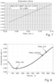
- Fig. 5 illustrates the change of the ratio of the electrical conductivity of the water passed through the filter and the electrical conductivity of the raw water.
- the volume corresponding to a pH of 6.8 is about 750 liters.
- the ratio corresponding to a volume of 750 liters is about 0,85. Combining this information leads to the conclusion that a pH of 6.8 corresponds to a ratio of 0,85. This is why this ratio is named ratio_6.8. Further, it is possible to extract from the curve in Fig. 5 the lowest ratio, ratio_min, which has a value of 0.64 in this case.
- ratio_min there is a direct link between the ratio_min and the ratio_6.8.
- a filter was tested for different water compositions (ratio TH / Alk.).
- the filter used for the tests had a fixed given amount of WAC ion exchange resin.
- the resin was always conditioned in the same way, using Na + as buffer with always the same quantity located between 0.1 and 1.0 mol of Na + per liter of resin.
- the bypass was adjusted from 10 to 70 % according to the water alkalinity.
- ratio_min and ratio_6.8 were linear as a function of the ratio TH /Alk.
- Ratio_min and ratio_6.8 depend on the WAC ion exchange resin used, its capacity and the amount of buffer loaded (here Na + ), as well as on the raw water composition, especially the ratio TH / Alk.
- the ratio_6.8 corresponding to the exhaustion point is linear to the ratio_min.
- This curve is characteristic for a defined filter type and can be used as exhaustion criteria.
- a device can be configured to determine a warning ratio (ratio_warning) to give information to a user of the device that the filter is coming to the end of its lifetime and will need to be replaced soon.
- the device according to the invention comprises three LEDs (green, orange and red) as optical signaling devices.
- the lightning of the LEDs is controlled as follows: • Green ON: ratio_actual ⁇ ratio_warning • Orange ON: ratio_warning ⁇ ratio_actual ⁇ ratio_6.8 • Red ON: ratio_actual > ratio_6.8
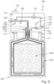
- the device 100 shown in Fig. 9 comprises a base unit 115 and an exchangeable filter 105.
- the base unit 115 and the filter 105 are connected via a screw connection.
- the filter comprises an external thread 117 and the base unit comprises an internal thread 118.
- the sealing rings 113 and 114 are arranged at an interface between the filter 105 and the base unit 115.
- the base unit comprises an inlet line 101 for a first stream of raw water, an outlet line 107 for a second stream of water with decreased hardness exiting from the filter 105 and a bypass line 103.
- the first stream of raw water is split into two partial streams.
- One of the partial streams is led via line 104 to the filter 105.
- the other partial stream flows through the bypass line 103.
- the ratio between the two partial streams can be regulated by means of the valve 112.
- water which has exited from the filter 105 can be blended with raw water from the bypass line 103.
- Via the outlet line 107 the water can exit from the device 100. Arrows are used to illustrate the directions in which the water streams flow within the device.
- the filter 105 comprises an inlet 105a for the first stream of raw water and an outlet 105b for the second stream of water with decreased hardness.
- the inlet line 101 of the base unit 115 is coupled to the inlet 105a of the filter 105 and the outlet line 107 of the base unit 115 is coupled to the outlet 105b of the filter 105.
- the filter 105 contains a WAC resin 105d operated under H + form and buffered with Na + .
- the WAC resin 105d is contained in a cartridge 105c.
- Na + ions and H + ions fixed on the WAC resin 105d are exchanged against hardness. Initially primarily Na + ions are exchanged. Later, the output of H + ions increases and the output of Na + ions decreases.
- the device 100 comprises two sensors 109 and 110 for measuring electrical conductivity of the water flowing through the device.
- Sensor 109 is positioned at the outlet line 107.
- Sensor 110 is positioned at the inlet line 101.
- device 100 comprises sensor 108 for detecting a water flow through the filter 105.
- the sensor 108 gives information about the presence of a water flow through the filter 105.
- the sensors 108 to 110 are connected to an electronic control unit 111, as shown in Fig. 2 .
- the electronic control unit is not visible in the cross-section showed in Fig. 9 .
- the device 100 further comprises 3 LEDs 116 as a filter replacement indicator. With the help of the LEDs 116 it is possible to give a first warning prior to the filter exhaustion in order to inform the user that the filter is at the end of its lifetime and a second warning when the filter is exhausted, as already described above.
Landscapes
- Chemical & Material Sciences (AREA)
- Organic Chemistry (AREA)
- Chemical Kinetics & Catalysis (AREA)
- Life Sciences & Earth Sciences (AREA)
- Hydrology & Water Resources (AREA)
- Engineering & Computer Science (AREA)
- Environmental & Geological Engineering (AREA)
- Water Supply & Treatment (AREA)
- Treatment Of Water By Ion Exchange (AREA)
Claims (14)
- Wasserenthärtungsvorrichtung (100), umfassenda. einen Filter (105), der dazu ausgelegt ist, eine Härte einer ersten Rohwasserströmung zu verringern, um eine zweite Wasserströmung mit verringerter Härte zu erzeugen,b. einen ersten Sensor (109), der dazu ausgelegt ist, eine elektrische Leitfähigkeit und/oder einen elektrischen Widerstand der ersten Strömung zu messen,c. einen zweiten Sensor (110), der dazu ausgelegt ist, eine elektrische Leitfähigkeit und/oder einen elektrischen Widerstand der zweiten Strömung zu messen, undd. optional einen dritten Sensor (108) zum Detektieren einer Wasserströmung durch den Filter (105),
wobeie. der Filter (105) ein Ionenaustauschharz (105d) umfasst, das in einem H+-Modus betrieben wird und das mit mindestens einem Salz gepuffert ist, das ausgewählt ist aus der Gruppe aus einem Kaliumsalz (K+), einem Natriumsalz (Na+) und einem Lithiumsalz (Li+),f. die Vorrichtung (100) eine elektronische Steuereinheit (111) umfasst, die mit dem ersten Sensor (109), mit dem zweiten Sensor (110) und optional, falls die Vorrichtung den dritten Sensor umfasst, mit dem dritten Sensor (108) verbunden ist, und die einen internen Datenspeicher und eine Datenverarbeitungseinheit umfasst, undg. die Vorrichtung dazu ausgelegt ist, ein Verhältnis zwischen der gemessenen elektrischen Leitfähigkeit und/oder dem gemessenen elektrischen Widerstand der zweiten Strömung und der gemessenen elektrischen Leitfähigkeit und/oder dem gemessenen elektrischen Widerstand der ersten Strömung zu bestimmen und das Verhältnis als einen Indikator für den Erschöpfungszustand des Filters (105) zu verwenden. - Wasserenthärtungsvorrichtung nach Anspruch 1 mit den folgenden zusätzlichen Merkmalen:a. Die Vorrichtung (100) umfasst eine Basiseinheit (115).b. Der erste Sensor (109), der zweite Sensor (110) und der dritte Sensor (108) sind integrale Bestandteile der Basiseinheit (115).c. Der Filter (105) ist als austauschbarer Filter ausgelegt, der lösbar mit der Basiseinheit (115) verbindbar ist.
- Wasserenthärtungsvorrichtung nach Anspruch 2 mit den folgenden zusätzlichen Merkmalen:a. Die Basiseinheit (115) und der Filter (105) sind über eine Schraubverbindung verbunden.b. Der Filter (105) weist einen Einlass (105a) für die erste Strömung und einen Auslass (105b) für die zweite Strömung auf.c. Die Basiseinheit (115) umfasst eine Einlassleitung (101) für die erste Strömung und eine Auslassleitung (107) für die zweite Strömung.d. Die Einlassleitung (101) der Basiseinheit (115) ist mit dem Einlass (105a) des Filters (105) gekoppelt und die Auslassleitung (107) der Basiseinheit (115) ist mit dem Auslass (105b) des Filters (105) gekoppelt.
- Wasserenthärtungsvorrichtung nach Anspruch 2 oder Anspruch 3 mit den folgenden zusätzlichen Merkmalen:a. Der erste Sensor (109) ist als eine Elektrolysezelle ausgelegt, die in der Lage ist, einen Strom an die erste Strömung anzulegen.b. Der zweite Sensor (110) ist als eine Elektrolysezelle ausgelegt, die in der Lage ist, einen Strom an die zweite Strömung anzulegen.c. Der erste Sensor (109) ist innerhalb der Einlassleitung (101) der Basiseinheit (115) oder an einem Eingang der Einlassleitung (101) der Basiseinheit (115) positioniert.d. Der zweite Sensor (110) ist innerhalb der Auslassleitung (107) der Basiseinheit (115) oder an einem Eingang der Auslassleitung (107) der Basiseinheit (115) positioniert.
- Wasserenthärtungsvorrichtung nach einem der Ansprüche 2 bis 4 mit dem folgenden zusätzlichen Merkmal:a. Die elektronische Steuereinheit (111) ist ein integraler Bestandteil der Basiseinheit (115).
- Wasserenthärtungsvorrichtung nach einem der vorhergehenden Ansprüche mit den folgenden zusätzlichen Merkmalen:a. Das Ionenaustauschharz (105d) ist in einer Kartusche (105c) enthalten.b. Das Ionenaustauschharz (105d) ist ein schwach saures kationisches Ionenaustauschharz (WAC-Harz).
- Wasserenthärtungsvorrichtung nach einem der Ansprüche 2 bis 6 mit den folgenden zusätzlichen Merkmalen:a. Die Vorrichtung (100) weist eine Bypassleitung (103) zum Mischen der zweiten Strömung mit Wasser der ersten Strömung auf.b. Die Bypassleitung (103) verbindet die Einlassleitung (101) der Basiseinheit (115) mit der Auslassleitung (107) der Basiseinheit (115).c. Die Bypassleitung (103) umfasst ein Ventil (112) zum Regeln der Menge an Wasser der ersten Strömung, die mit der zweiten Strömung gemischt wird.d. Die Bypassleitung (103) ist in die Basiseinheit (115) integriert.
- Wasserenthärtungsvorrichtung nach einem der Ansprüche 2 bis 7 mit den folgenden zusätzlichen Merkmalen:a. Die Vorrichtung (100) umfasst einen Filteraustauschindikator (116), der dazu ausgelegt ist, anzuzeigen, dass der Filter (105) das Ende seiner Lebensdauer erreicht hat oder sich nahe dem Ende seiner Lebensdauer befindet.b. Der Austauschindikator (116) ist eine optische Signalvorrichtung und/oder ein Schallgeber.c. Der Filteraustauschindikator (116) ist ein integraler Bestandteil der Basiseinheit (115).d. Der Filteraustauschindikator (116) ist mit der elektronischen Steuereinheit (111) verbunden.e. Die elektronische Steuereinheit (111) ist dazu ausgelegt, den Austauschindikator (116) zum Ausgeben eines Warnsignals in Abhängigkeit von elektrischen Eigenschaften der ersten und der zweiten Strömung auszulösen, die durch den ersten Sensor (109) und den zweiten Sensor (110) gemessen werden.
- Wasserenthärtungsvorrichtung nach einem der Ansprüche 2 bis 8 mit den folgenden zusätzlichen Merkmalen:a. Die Vorrichtung (100) umfasst eine Halterung zur stationären Installation der Basiseinheit (115).b. Die Halterung umfasst ein oder mehrere Löcher und ist mit der Basiseinheit (115) verbunden oder verbindbar.
- Verfahren zum Betreiben einer Wasserenthärtungsvorrichtung, insbesondere einer Vorrichtung (100) nach Anspruch 1, umfassend die folgenden Schrittea. Leiten einer ersten Rohwasserströmung durch einen Filter (105), der dazu ausgelegt ist, eine Härte der Strömung zu verringern, um eine zweite Wasserströmung mit verringerter Härte zu erzeugen,b. Messen einer elektrischen Leitfähigkeit oder eines elektrischen Widerstands der ersten Strömung mit einem ersten Sensor (109),c. Messen einer elektrischen Leitfähigkeit oder eines elektrischen Widerstands der zweiten Strömung mit einem zweiten Sensor (110),d. Bestimmen eines Verhältnisses zwischen der gemessenen elektrischen Leitfähigkeit oder dem gemessenen elektrischen Widerstand der zweiten Strömung und der gemessenen elektrischen Leitfähigkeit oder dem gemessenen elektrischen Widerstand der ersten Strömung unde. Verwenden des Verhältnisses als einen Indikator für den Erschöpfungszustand des Filters (105),
wobeif. der Filter (105) ein Ionenaustauschharz (105d) umfasst, das in einem H+-Mode betrieben wird, undg. der Filter (105) mit mindestens einem Salz gepuffert ist, das ausgewählt ist aus der Gruppe aus einem Kaliumsalz (K+), einem Natriumsalz (Na+) und einem Lithiumsalz (Li+). - Verfahren nach Anspruch 10 mit dem folgenden zusätzlichen Schritt oder Merkmal:a. Das Verhältnis ist das Verhältnis zwischen der elektrischen Leitfähigkeit der zweiten Strömung und der elektrischen Leitfähigkeit der ersten Strömung.
- Verfahren nach Anspruch 10 oder Anspruch 11 mit den folgenden zusätzlichen Schritten oder Merkmalen:a. Eine Sequenz von Messungen der elektrischen Leitfähigkeiten der ersten und der zweiten Strömung wird durchgeführt.b. Aus den Ergebnissen jeder der Messungen wird das Verhältnis zwischen der elektrischen Leitfähigkeit der zweiten Strömung und der elektrischen Leitfähigkeit der ersten Strömung bestimmt, wodurch eine Sequenz von Verhältnissen erhalten wird.c. Das niedrigste Verhältnis ratio_min wird bestimmt.d. Ein Schwellwert ratio_exhaust wird in Abhängigkeit von ratio_min bestimmt.
- Verfahren nach Anspruch 12 mit den folgenden zusätzlichen Schritten:a. Ein Schwellwert ratio_exhaust wird gemäß folgender Formel berechnet
 b. Ein Schwellwert ratio_exhaust wird gemäß folgender Formel berechnet

- Verfahren nach einem der Ansprüche 10 bis 13 mit den folgenden zusätzlichen Schritten oder Merkmalen:a. Ein Warnsignal wird ausgegeben, wenn das Verhältnis einen Schwellwert ratio_warning überschreitet.b. Der Schwellwert ratio_warning ist ein vorbestimmter Wert.c. Der Schwellwert ratio_warning wird aus Daten berechnet, die durch die Messungen der elektrischen Eigenschaften der ersten und der zweiten Strömung erhalten werden.d. Der Schwellenwert ratio_warning wird aus dem Verhältnis zwischen der elektrischen Leitfähigkeit der zweiten Strömung und der elektrischen Leitfähigkeit der ersten Strömung berechnet.e. Der Schwellwert ratio_warning wird in Abhängigkeit von ratio_exhaust bestimmt.
Priority Applications (6)
| Application Number | Priority Date | Filing Date | Title |
|---|---|---|---|
| ES17155008T ES3022637T3 (en) | 2017-02-07 | 2017-02-07 | Water softening device and method to operate a water softening device |
| EP17155008.0A EP3357868B1 (de) | 2017-02-07 | 2017-02-07 | Wasserenthärtungsvorrichtung und verfahren zum betrieb einer wasserenthärtungsvorrichtung |
| US16/472,024 US11130684B2 (en) | 2017-02-07 | 2018-02-01 | Water softening device and method of operating a water softening device |
| PCT/EP2018/052571 WO2018146002A1 (en) | 2017-02-07 | 2018-02-01 | Water softening device and method to operate a water softening device |
| JP2019531462A JP7154213B2 (ja) | 2017-02-07 | 2018-02-01 | 軟水化装置及び軟水化装置の操作方法 |
| RU2019126737A RU2731092C1 (ru) | 2017-02-07 | 2018-02-01 | Водоумягчительное устройство и способ эксплуатиции водоумягчительного устройства |
Applications Claiming Priority (1)
| Application Number | Priority Date | Filing Date | Title |
|---|---|---|---|
| EP17155008.0A EP3357868B1 (de) | 2017-02-07 | 2017-02-07 | Wasserenthärtungsvorrichtung und verfahren zum betrieb einer wasserenthärtungsvorrichtung |
Publications (2)
| Publication Number | Publication Date |
|---|---|
| EP3357868A1 EP3357868A1 (de) | 2018-08-08 |
| EP3357868B1 true EP3357868B1 (de) | 2025-03-26 |
Family
ID=57995064
Family Applications (1)
| Application Number | Title | Priority Date | Filing Date |
|---|---|---|---|
| EP17155008.0A Active EP3357868B1 (de) | 2017-02-07 | 2017-02-07 | Wasserenthärtungsvorrichtung und verfahren zum betrieb einer wasserenthärtungsvorrichtung |
Country Status (6)
| Country | Link |
|---|---|
| US (1) | US11130684B2 (de) |
| EP (1) | EP3357868B1 (de) |
| JP (1) | JP7154213B2 (de) |
| ES (1) | ES3022637T3 (de) |
| RU (1) | RU2731092C1 (de) |
| WO (1) | WO2018146002A1 (de) |
Families Citing this family (8)
| Publication number | Priority date | Publication date | Assignee | Title |
|---|---|---|---|---|
| US11261705B2 (en) * | 2018-08-13 | 2022-03-01 | Saudi Arabian Oil Company | Systems and methods for treating fluids in oilfield facilities |
| US12454457B2 (en) * | 2019-11-08 | 2025-10-28 | Evatec Co., Ltd. | Method for preparing hypochlorous acid aqueous solution and method for regenerating weakly acidic cation exchanger |
| DE102020106793B4 (de) | 2020-03-12 | 2026-07-16 | Bwt Holding Gmbh | Filterkopf sowie System zur Wasseraufbereitung |
| DE102020127198A1 (de) * | 2020-10-15 | 2022-04-21 | Vivonic Gmbh | Vorrichtung und Verfahren zur Überwachung einer Enthärtungseinrichtung für Wasser |
| CN116531840B (zh) * | 2022-01-26 | 2025-07-25 | 佛山市云米电器科技有限公司 | 一种对树脂型净水滤芯进行使用寿命判断的方法 |
| DE102022107575B4 (de) * | 2022-03-30 | 2026-07-16 | Grünbeck AG | Wasserbehandlungsanlage und Verfahren zum Betrieb einer Wasserbehandlungsanlage |
| CN117185506B (zh) * | 2023-08-16 | 2025-08-05 | 重庆大学 | 一种锅炉给水硬度智能控制系统 |
| DE102024125892A1 (de) * | 2024-09-10 | 2026-03-12 | UWS Technologie GmbH | Kartusche zur Aufbereitung von Wasser, Wasseraufbereitungsgebinde, Wasseraufbereitungsgebindesatz |
Citations (11)
| Publication number | Priority date | Publication date | Assignee | Title |
|---|---|---|---|---|
| US5234601A (en) | 1992-09-28 | 1993-08-10 | Autotrol Corporation | Apparatus and method for controlling regeneration of a water treatment system |
| EP1002582A1 (de) | 1998-11-02 | 2000-05-24 | V-Zug AG | Verfahren zum Betrieb eines Ionentauschers |
| US20060011523A1 (en) | 2002-04-04 | 2006-01-19 | Harald Schrott | Water filter cartridge comprising an exchangeable testing unit that contains a conductance sensor |
| US20070215531A1 (en) | 2006-03-17 | 2007-09-20 | Andreas Wawrla | Water-treatment appliance |
| US20080230451A1 (en) | 2005-03-07 | 2008-09-25 | Koninklijke Philips Electronics N.V. | Ion Exchange Cartridge |
| DE102010003636A1 (de) | 2010-04-01 | 2011-10-06 | Judo Wasseraufbereitung Gmbh | Verfahren zur Überwachung einer Wasserbehandlungsanlage, insbesondere einer Kreislauf-Befüllungsanlage |
| EP2481713A1 (de) | 2011-01-28 | 2012-08-01 | Judo Wasseraufbereitung GmbH | Verfahren zum Betrieb einer Wasserenthärtungsanlage und Wasserenthärtungsanlage zur Durchführung des Verfahrens |
| US20130328579A1 (en) | 2011-01-26 | 2013-12-12 | VWS (UK) Limited | Monitoring Method |
| WO2014033145A1 (en) | 2012-08-29 | 2014-03-06 | Brita Professional Gmbh & Co. Kg | Processing data obtained by operating a liquid treatment system |
| EP2952481A1 (de) | 2014-06-06 | 2015-12-09 | Brita GmbH | Verfahren und System zur Überwachung des Betriebs einer Flüssigkeitsbehandlungsvorrichtung mit einer auswechselbaren Flüssigkeitsbehandlungskartusche |
| EP3034474A1 (de) | 2015-09-10 | 2016-06-22 | Brita GmbH | Vorrichtung und verfahren zur konditionierung einer wässrigen flüssigkeit |
Family Cites Families (10)
| Publication number | Priority date | Publication date | Assignee | Title |
|---|---|---|---|---|
| JPS6046195U (ja) * | 1983-09-08 | 1985-04-01 | 三浦工業株式会社 | 硬水軟化装置の硬度漏れ検知装置 |
| JPS60172391A (ja) * | 1984-02-20 | 1985-09-05 | Kurita Water Ind Ltd | 純水製造装置 |
| JPH01218680A (ja) * | 1988-02-25 | 1989-08-31 | Nomura Micro Sci Kk | イオン交換装置のブレーク監視方法 |
| JPH09271769A (ja) * | 1996-04-03 | 1997-10-21 | Kaoru Asada | 軟水化装置及び軟水化装置の保守方法 |
| DE102006028168A1 (de) | 2006-06-16 | 2007-12-20 | Uhde Gmbh | Vorrichtung zur elektrochemischen Wasseraufbereitung |
| JP2006281216A (ja) | 2006-07-26 | 2006-10-19 | Mitsubishi Rayon Co Ltd | 浄水器 |
| WO2009100000A2 (en) * | 2008-01-31 | 2009-08-13 | Oxygenator Water Technologies, Inc. | Apparatus and method for improved electrolytic water treatment process |
| CA2775712A1 (en) | 2009-09-29 | 2011-04-07 | Pentair Residential Filtration, Llc | Twin tank water treatment system and method |
| US8231791B2 (en) | 2010-01-14 | 2012-07-31 | Culligan International Company | System and method for controlling multiple sized water softening tanks |
| US20140054211A1 (en) * | 2011-04-26 | 2014-02-27 | Brita Gmbh | System and method for conditioning a liquid such as water |
-
2017
- 2017-02-07 EP EP17155008.0A patent/EP3357868B1/de active Active
- 2017-02-07 ES ES17155008T patent/ES3022637T3/es active Active
-
2018
- 2018-02-01 RU RU2019126737A patent/RU2731092C1/ru active
- 2018-02-01 US US16/472,024 patent/US11130684B2/en active Active
- 2018-02-01 JP JP2019531462A patent/JP7154213B2/ja active Active
- 2018-02-01 WO PCT/EP2018/052571 patent/WO2018146002A1/en not_active Ceased
Patent Citations (11)
| Publication number | Priority date | Publication date | Assignee | Title |
|---|---|---|---|---|
| US5234601A (en) | 1992-09-28 | 1993-08-10 | Autotrol Corporation | Apparatus and method for controlling regeneration of a water treatment system |
| EP1002582A1 (de) | 1998-11-02 | 2000-05-24 | V-Zug AG | Verfahren zum Betrieb eines Ionentauschers |
| US20060011523A1 (en) | 2002-04-04 | 2006-01-19 | Harald Schrott | Water filter cartridge comprising an exchangeable testing unit that contains a conductance sensor |
| US20080230451A1 (en) | 2005-03-07 | 2008-09-25 | Koninklijke Philips Electronics N.V. | Ion Exchange Cartridge |
| US20070215531A1 (en) | 2006-03-17 | 2007-09-20 | Andreas Wawrla | Water-treatment appliance |
| DE102010003636A1 (de) | 2010-04-01 | 2011-10-06 | Judo Wasseraufbereitung Gmbh | Verfahren zur Überwachung einer Wasserbehandlungsanlage, insbesondere einer Kreislauf-Befüllungsanlage |
| US20130328579A1 (en) | 2011-01-26 | 2013-12-12 | VWS (UK) Limited | Monitoring Method |
| EP2481713A1 (de) | 2011-01-28 | 2012-08-01 | Judo Wasseraufbereitung GmbH | Verfahren zum Betrieb einer Wasserenthärtungsanlage und Wasserenthärtungsanlage zur Durchführung des Verfahrens |
| WO2014033145A1 (en) | 2012-08-29 | 2014-03-06 | Brita Professional Gmbh & Co. Kg | Processing data obtained by operating a liquid treatment system |
| EP2952481A1 (de) | 2014-06-06 | 2015-12-09 | Brita GmbH | Verfahren und System zur Überwachung des Betriebs einer Flüssigkeitsbehandlungsvorrichtung mit einer auswechselbaren Flüssigkeitsbehandlungskartusche |
| EP3034474A1 (de) | 2015-09-10 | 2016-06-22 | Brita GmbH | Vorrichtung und verfahren zur konditionierung einer wässrigen flüssigkeit |
Also Published As
| Publication number | Publication date |
|---|---|
| ES3022637T3 (en) | 2025-05-28 |
| US20190352198A1 (en) | 2019-11-21 |
| WO2018146002A1 (en) | 2018-08-16 |
| JP7154213B2 (ja) | 2022-10-17 |
| EP3357868A1 (de) | 2018-08-08 |
| JP2020506794A (ja) | 2020-03-05 |
| RU2731092C1 (ru) | 2020-08-28 |
| US11130684B2 (en) | 2021-09-28 |
Similar Documents
| Publication | Publication Date | Title |
|---|---|---|
| EP3357868A1 (de) | Wasserenthärtungsvorrichtung und verfahren zum betrieb einer wasserenthärtungsvorrichtung | |
| EP3366373B1 (de) | Wasserenthärtungsvorrichtung und verfahren zum betrieb einer wasserenthärtungsvorrichtung | |
| AU2008333698B2 (en) | Method for operating a water softening system having two calibration characteristics and associated water softening system | |
| KR102217868B1 (ko) | 형광을 통한 수질 경도 모니터링 | |
| EP2823877B1 (de) | Filterprüfung einer Wasseraufbereitungsanlage | |
| DE102011114912B4 (de) | Vorrichtung zur Erzeugung von Reinstwasser | |
| CN104603614A (zh) | 用于测定水的暂时硬度的方法和装置 | |
| JP6082192B2 (ja) | 純水製造装置 | |
| CN113811513A (zh) | 在线水硬度传感器和软水器控制系统 | |
| EP2668137B1 (de) | Überwachungsverfahren | |
| CN104603062A (zh) | 调节用于控制流体处理装置的操作的系统 | |
| WO2019191589A1 (en) | Method for determining hardness concentration using a monovalent ion selective electrode | |
| WO2002028517A1 (en) | Method for early detection of the occurrence of scaling in the purification of water | |
| CH705686A2 (de) | Verfahren und Vorrichtung zur Bestimmung der Wasserhärte. | |
| KR20110116649A (ko) | 정량펌프를 이용한 필터 성능 테스트 장치 및 그를 이용한 필터 성능 테스트 방법 | |
| KR101238961B1 (ko) | 추적자 분석 시스템 | |
| JP4864671B2 (ja) | 水質異常検出装置、水質異常検出方法及び水処理装置 | |
| CN100343665C (zh) | 判断离子交换树脂饱和点的方法 | |
| JP2020037079A (ja) | 脱硫排水試料あるいは脱硫吸収液試料からのhatsの分離方法及び分析方法並びに脱硫装置の運用方法 | |
| JPH09271770A (ja) | カートリッジ式純水製造装置 | |
| JP3864539B2 (ja) | イオン交換樹脂の性能評価方法 | |
| JP4204712B2 (ja) | カチオン検出装置、カチオン検出方法、水処理装置、及び超純水製造装置 | |
| JP2014163847A (ja) | 表面付着物測定装置 | |
| JP3352859B2 (ja) | イオン交換樹脂を用いたショ糖液の脱塩方法 | |
| CN109557244A (zh) | 次氯酸钠溶液中游离碱含量的测定方法 |
Legal Events
| Date | Code | Title | Description |
|---|---|---|---|
| PUAI | Public reference made under article 153(3) epc to a published international application that has entered the european phase |
Free format text: ORIGINAL CODE: 0009012 |
|
| STAA | Information on the status of an ep patent application or granted ep patent |
Free format text: STATUS: THE APPLICATION HAS BEEN PUBLISHED |
|
| AK | Designated contracting states |
Kind code of ref document: A1 Designated state(s): AL AT BE BG CH CY CZ DE DK EE ES FI FR GB GR HR HU IE IS IT LI LT LU LV MC MK MT NL NO PL PT RO RS SE SI SK SM TR |
|
| AX | Request for extension of the european patent |
Extension state: BA ME |
|
| STAA | Information on the status of an ep patent application or granted ep patent |
Free format text: STATUS: REQUEST FOR EXAMINATION WAS MADE |
|
| 17P | Request for examination filed |
Effective date: 20181022 |
|
| RBV | Designated contracting states (corrected) |
Designated state(s): AL AT BE BG CH CY CZ DE DK EE ES FI FR GB GR HR HU IE IS IT LI LT LU LV MC MK MT NL NO PL PT RO RS SE SI SK SM TR |
|
| STAA | Information on the status of an ep patent application or granted ep patent |
Free format text: STATUS: EXAMINATION IS IN PROGRESS |
|
| 17Q | First examination report despatched |
Effective date: 20191112 |
|
| GRAP | Despatch of communication of intention to grant a patent |
Free format text: ORIGINAL CODE: EPIDOSNIGR1 |
|
| STAA | Information on the status of an ep patent application or granted ep patent |
Free format text: STATUS: GRANT OF PATENT IS INTENDED |
|
| RIC1 | Information provided on ipc code assigned before grant |
Ipc: B01J 47/024 20170101ALN20241009BHEP Ipc: C02F 1/42 20060101ALI20241009BHEP Ipc: C02F 1/00 20060101AFI20241009BHEP |
|
| INTG | Intention to grant announced |
Effective date: 20241023 |
|
| GRAS | Grant fee paid |
Free format text: ORIGINAL CODE: EPIDOSNIGR3 |
|
| GRAA | (expected) grant |
Free format text: ORIGINAL CODE: 0009210 |
|
| STAA | Information on the status of an ep patent application or granted ep patent |
Free format text: STATUS: THE PATENT HAS BEEN GRANTED |
|
| P01 | Opt-out of the competence of the unified patent court (upc) registered |
Free format text: CASE NUMBER: APP_5854/2025 Effective date: 20250204 |
|
| AK | Designated contracting states |
Kind code of ref document: B1 Designated state(s): AL AT BE BG CH CY CZ DE DK EE ES FI FR GB GR HR HU IE IS IT LI LT LU LV MC MK MT NL NO PL PT RO RS SE SI SK SM TR |
|
| REG | Reference to a national code |
Ref country code: GB Ref legal event code: FG4D |
|
| REG | Reference to a national code |
Ref country code: CH Ref legal event code: EP |
|
| REG | Reference to a national code |
Ref country code: DE Ref legal event code: R096 Ref document number: 602017088502 Country of ref document: DE |
|
| REG | Reference to a national code |
Ref country code: IE Ref legal event code: FG4D |
|
| REG | Reference to a national code |
Ref country code: ES Ref legal event code: FG2A Ref document number: 3022637 Country of ref document: ES Kind code of ref document: T3 Effective date: 20250528 |
|
| PG25 | Lapsed in a contracting state [announced via postgrant information from national office to epo] |
Ref country code: RS Free format text: LAPSE BECAUSE OF FAILURE TO SUBMIT A TRANSLATION OF THE DESCRIPTION OR TO PAY THE FEE WITHIN THE PRESCRIBED TIME-LIMIT Effective date: 20250626 |
|
| PG25 | Lapsed in a contracting state [announced via postgrant information from national office to epo] |
Ref country code: FI Free format text: LAPSE BECAUSE OF FAILURE TO SUBMIT A TRANSLATION OF THE DESCRIPTION OR TO PAY THE FEE WITHIN THE PRESCRIBED TIME-LIMIT Effective date: 20250326 |
|
| REG | Reference to a national code |
Ref country code: LT Ref legal event code: MG9D |
|
| PG25 | Lapsed in a contracting state [announced via postgrant information from national office to epo] |
Ref country code: NO Free format text: LAPSE BECAUSE OF FAILURE TO SUBMIT A TRANSLATION OF THE DESCRIPTION OR TO PAY THE FEE WITHIN THE PRESCRIBED TIME-LIMIT Effective date: 20250626 |
|
| PG25 | Lapsed in a contracting state [announced via postgrant information from national office to epo] |
Ref country code: HR Free format text: LAPSE BECAUSE OF FAILURE TO SUBMIT A TRANSLATION OF THE DESCRIPTION OR TO PAY THE FEE WITHIN THE PRESCRIBED TIME-LIMIT Effective date: 20250326 |
|
| PG25 | Lapsed in a contracting state [announced via postgrant information from national office to epo] |
Ref country code: LV Free format text: LAPSE BECAUSE OF FAILURE TO SUBMIT A TRANSLATION OF THE DESCRIPTION OR TO PAY THE FEE WITHIN THE PRESCRIBED TIME-LIMIT Effective date: 20250326 |
|
| PG25 | Lapsed in a contracting state [announced via postgrant information from national office to epo] |
Ref country code: GR Free format text: LAPSE BECAUSE OF FAILURE TO SUBMIT A TRANSLATION OF THE DESCRIPTION OR TO PAY THE FEE WITHIN THE PRESCRIBED TIME-LIMIT Effective date: 20250627 Ref country code: BG Free format text: LAPSE BECAUSE OF FAILURE TO SUBMIT A TRANSLATION OF THE DESCRIPTION OR TO PAY THE FEE WITHIN THE PRESCRIBED TIME-LIMIT Effective date: 20250326 |
|
| REG | Reference to a national code |
Ref country code: NL Ref legal event code: MP Effective date: 20250326 |
|
| PG25 | Lapsed in a contracting state [announced via postgrant information from national office to epo] |
Ref country code: NL Free format text: LAPSE BECAUSE OF FAILURE TO SUBMIT A TRANSLATION OF THE DESCRIPTION OR TO PAY THE FEE WITHIN THE PRESCRIBED TIME-LIMIT Effective date: 20250326 |
|
| PG25 | Lapsed in a contracting state [announced via postgrant information from national office to epo] |
Ref country code: SE Free format text: LAPSE BECAUSE OF FAILURE TO SUBMIT A TRANSLATION OF THE DESCRIPTION OR TO PAY THE FEE WITHIN THE PRESCRIBED TIME-LIMIT Effective date: 20250326 |
|
| PG25 | Lapsed in a contracting state [announced via postgrant information from national office to epo] |
Ref country code: SM Free format text: LAPSE BECAUSE OF FAILURE TO SUBMIT A TRANSLATION OF THE DESCRIPTION OR TO PAY THE FEE WITHIN THE PRESCRIBED TIME-LIMIT Effective date: 20250326 |
|
| PG25 | Lapsed in a contracting state [announced via postgrant information from national office to epo] |
Ref country code: PT Free format text: LAPSE BECAUSE OF FAILURE TO SUBMIT A TRANSLATION OF THE DESCRIPTION OR TO PAY THE FEE WITHIN THE PRESCRIBED TIME-LIMIT Effective date: 20250728 |
|
| PG25 | Lapsed in a contracting state [announced via postgrant information from national office to epo] |
Ref country code: PL Free format text: LAPSE BECAUSE OF FAILURE TO SUBMIT A TRANSLATION OF THE DESCRIPTION OR TO PAY THE FEE WITHIN THE PRESCRIBED TIME-LIMIT Effective date: 20250326 |
|
| PG25 | Lapsed in a contracting state [announced via postgrant information from national office to epo] |
Ref country code: EE Free format text: LAPSE BECAUSE OF FAILURE TO SUBMIT A TRANSLATION OF THE DESCRIPTION OR TO PAY THE FEE WITHIN THE PRESCRIBED TIME-LIMIT Effective date: 20250326 |
|
| PG25 | Lapsed in a contracting state [announced via postgrant information from national office to epo] |
Ref country code: RO Free format text: LAPSE BECAUSE OF FAILURE TO SUBMIT A TRANSLATION OF THE DESCRIPTION OR TO PAY THE FEE WITHIN THE PRESCRIBED TIME-LIMIT Effective date: 20250326 |
|
| PG25 | Lapsed in a contracting state [announced via postgrant information from national office to epo] |
Ref country code: SK Free format text: LAPSE BECAUSE OF FAILURE TO SUBMIT A TRANSLATION OF THE DESCRIPTION OR TO PAY THE FEE WITHIN THE PRESCRIBED TIME-LIMIT Effective date: 20250326 |
|
| PG25 | Lapsed in a contracting state [announced via postgrant information from national office to epo] |
Ref country code: IS Free format text: LAPSE BECAUSE OF FAILURE TO SUBMIT A TRANSLATION OF THE DESCRIPTION OR TO PAY THE FEE WITHIN THE PRESCRIBED TIME-LIMIT Effective date: 20250726 |
|
| REG | Reference to a national code |
Ref country code: DE Ref legal event code: R026 Ref document number: 602017088502 Country of ref document: DE |
|
| PLBI | Opposition filed |
Free format text: ORIGINAL CODE: 0009260 |
|
| REG | Reference to a national code |
Ref country code: CH Ref legal event code: L11 Free format text: ST27 STATUS EVENT CODE: U-0-0-L10-L11 (AS PROVIDED BY THE NATIONAL OFFICE) Effective date: 20251231 |
|
| PLAB | Opposition data, opponent's data or that of the opponent's representative modified |
Free format text: ORIGINAL CODE: 0009299OPPO |
|
| PG25 | Lapsed in a contracting state [announced via postgrant information from national office to epo] |
Ref country code: DK Free format text: LAPSE BECAUSE OF FAILURE TO SUBMIT A TRANSLATION OF THE DESCRIPTION OR TO PAY THE FEE WITHIN THE PRESCRIBED TIME-LIMIT Effective date: 20250326 |
|
| REG | Reference to a national code |
Ref country code: CH Ref legal event code: L10 Free format text: ST27 STATUS EVENT CODE: U-0-0-L10-L00 (AS PROVIDED BY THE NATIONAL OFFICE) Effective date: 20260114 |
|
| PG25 | Lapsed in a contracting state [announced via postgrant information from national office to epo] |
Ref country code: CZ Free format text: LAPSE BECAUSE OF FAILURE TO SUBMIT A TRANSLATION OF THE DESCRIPTION OR TO PAY THE FEE WITHIN THE PRESCRIBED TIME-LIMIT Effective date: 20250326 |
|
| PLAX | Notice of opposition and request to file observation + time limit sent |
Free format text: ORIGINAL CODE: EPIDOSNOBS2 |
|
| 26 | Opposition filed |
Opponent name: BRITA SE Effective date: 20251218 |
|
| R26 | Opposition filed (corrected) |
Opponent name: BRITA SE Effective date: 20251218 |
|
| REG | Reference to a national code |
Ref country code: CH Ref legal event code: U11 Free format text: ST27 STATUS EVENT CODE: U-0-0-U10-U11 (AS PROVIDED BY THE NATIONAL OFFICE) Effective date: 20260301 |
|
| PGFP | Annual fee paid to national office [announced via postgrant information from national office to epo] |
Ref country code: GB Payment date: 20260219 Year of fee payment: 10 |
|
| PGFP | Annual fee paid to national office [announced via postgrant information from national office to epo] |
Ref country code: ES Payment date: 20260319 Year of fee payment: 10 |
|
| PGFP | Annual fee paid to national office [announced via postgrant information from national office to epo] |
Ref country code: DE Payment date: 20260219 Year of fee payment: 10 |
|
| PGFP | Annual fee paid to national office [announced via postgrant information from national office to epo] |
Ref country code: AT Payment date: 20260216 Year of fee payment: 10 |
|
| PGFP | Annual fee paid to national office [announced via postgrant information from national office to epo] |
Ref country code: IT Payment date: 20260227 Year of fee payment: 10 |
|
| PGFP | Annual fee paid to national office [announced via postgrant information from national office to epo] |
Ref country code: FR Payment date: 20260223 Year of fee payment: 10 |
|
| PGFP | Annual fee paid to national office [announced via postgrant information from national office to epo] |
Ref country code: CH Payment date: 20260301 Year of fee payment: 10 |
|
| PLBB | Reply of patent proprietor to notice(s) of opposition received |
Free format text: ORIGINAL CODE: EPIDOSNOBS3 |
|
| PG25 | Lapsed in a contracting state [announced via postgrant information from national office to epo] |
Ref country code: LT Free format text: LAPSE BECAUSE OF FAILURE TO SUBMIT A TRANSLATION OF THE DESCRIPTION OR TO PAY THE FEE WITHIN THE PRESCRIBED TIME-LIMIT Effective date: 20250326 |
|
| REG | Reference to a national code |
Ref country code: AT Ref legal event code: UEP Ref document number: 1778914 Country of ref document: AT Kind code of ref document: T Effective date: 20250326 |