EP3358128A1 - Procédé permettant d'effectuer des opérations de cimentation - Google Patents
Procédé permettant d'effectuer des opérations de cimentation Download PDFInfo
- Publication number
- EP3358128A1 EP3358128A1 EP18159005.0A EP18159005A EP3358128A1 EP 3358128 A1 EP3358128 A1 EP 3358128A1 EP 18159005 A EP18159005 A EP 18159005A EP 3358128 A1 EP3358128 A1 EP 3358128A1
- Authority
- EP
- European Patent Office
- Prior art keywords
- assembly
- bore
- cement head
- body member
- pin
- Prior art date
- Legal status (The legal status is an assumption and is not a legal conclusion. Google has not performed a legal analysis and makes no representation as to the accuracy of the status listed.)
- Granted
Links
Images





Classifications
-
- E—FIXED CONSTRUCTIONS
- E21—EARTH OR ROCK DRILLING; MINING
- E21B—EARTH OR ROCK DRILLING; OBTAINING OIL, GAS, WATER, SOLUBLE OR MELTABLE MATERIALS OR A SLURRY OF MINERALS FROM WELLS
- E21B33/00—Sealing or packing boreholes or wells
- E21B33/02—Surface sealing or packing
- E21B33/03—Well heads; Setting-up thereof
- E21B33/068—Well heads; Setting-up thereof having provision for introducing objects or fluids into, or removing objects from, wells
-
- E—FIXED CONSTRUCTIONS
- E21—EARTH OR ROCK DRILLING; MINING
- E21B—EARTH OR ROCK DRILLING; OBTAINING OIL, GAS, WATER, SOLUBLE OR MELTABLE MATERIALS OR A SLURRY OF MINERALS FROM WELLS
- E21B33/00—Sealing or packing boreholes or wells
- E21B33/02—Surface sealing or packing
- E21B33/03—Well heads; Setting-up thereof
- E21B33/04—Casing heads; Suspending casings or tubings in well heads
- E21B33/05—Cementing-heads, e.g. having provision for introducing cementing plugs
-
- E—FIXED CONSTRUCTIONS
- E21—EARTH OR ROCK DRILLING; MINING
- E21B—EARTH OR ROCK DRILLING; OBTAINING OIL, GAS, WATER, SOLUBLE OR MELTABLE MATERIALS OR A SLURRY OF MINERALS FROM WELLS
- E21B33/00—Sealing or packing boreholes or wells
- E21B33/10—Sealing or packing boreholes or wells in the borehole
- E21B33/13—Methods or devices for cementing, for plugging holes, crevices or the like
Definitions
- the present invention pertains to a method and apparatus for performing cementing operations in oil or gas wells. More particularly, the present invention pertains to a method and apparatus for performing cementing operations in oil or gas wells using a remotely-operated rotating cement head having a high tensile strength.
- blowout preventer and wellhead assemblies When drilling from a fixed platform or other similar structure, a blowout preventer assembly is typically located on the platform or other structure. However, when drilling from a floating drilling rig, blowout preventer and wellhead assemblies are not located on the drilling rig, but rather on the sea floor. As a result, specialized equipment known as "subsea" or “subsurface” blowout preventer and wellhead assemblies must be utilized.
- cementing operations are frequently made more complicated by the use of such subsea equipment.
- a cement head is typically installed above the rig floor to provide a connection or interface between a rig's pipe lifting system and surface pumping equipment, on the one hand, and down hole work string or other tubulars extending into a well, on the other hand.
- Such cement heads must permit cement slurry to flow from a pumping assembly into the well, and should have sufficient flow capacity to permit high pressure pumping of large volumes of cement and other fluids at high flow rates.
- Such cement heads must also have sufficient tensile strength to support heavy weight tubulars extending from the surface into a well, and to accommodate raising and lowering of such tubular goods.
- Cement heads should also beneficially swivel in order to permit rotation of the tubular goods and/or other downhole equipment in a well while maintaining circulation from the surface pumping equipment into the down hole tubular goods extending into the well.
- Darts, balls, plugs and/or other objects are frequently pumped into a well in connection with conventional cementing operations.
- such items are suspended within a cementing head until the objects are released or "launched" at desired points during the cement pumping process. Once released, such items join the cement slurry flow and can be pumped down hole directly into a well.
- Such darts, balls, plugs and/or other objects should be beneficially held in place within the slurry flow passing through the cement head prior to being launched or released without being damaged or washed away by such slurry flow.
- cement heads must be positioned high above the rig floor during cementing operations.
- a cement head will typically be located out of reach of personnel working on the rig floor, making it difficult for such personnel to easily access the cement head in order to actuate valves and/or launch items into the well.
- personnel must be hoisted off the rig floor using a makeshift seat or harness attached to a winch or other lifting device in order to reach the cement head to actuate valves and/or launch darts, balls, plugs or other objects.
- Such personnel are at risk of falling and suffering serious injury or death.
- such personnel are frequently required to carry heavy bars, wrenches and/or other tools used to manipulate valves or other equipment on such cement heads. These bars, wrenches and/or other heavy tools are at risk of being accidentally dropped on people or equipment on the rig floor below.
- a lifting top drive cement head that permits cement flow into the cement head from above, and has a high tensile strength as well as the ability to rotate or swivel.
- Valves used to isolate or restrict flow through the cement head, as well as launching mechanisms for releasing darts, balls, plugs and/or other objects into the slurry flow can be remotely actuated from a safe distance to eliminate the need for lifting personnel off the rig floor.
- Audible and/or visual indicators should also be provided to alert personnel on or in the vicinity of the rig floor about the operation of various elements of the tool and/or the status of objects launched into a well.
- US 5950724 A discloses a cement head comprising:
- the present invention comprises a cement head that can be situated below a top-drive unit, and permits cement to flow through such cement head and into a wellbore below.
- the cement head of the present invention has a high tensile strength, as well as the ability to swivel or rotate about a central (typically vertical) axis.
- the present invention also permits the use of darts, setting plugs, balls, wipers and/or other objects which can be held in place within the cement head without being damaged or washed away by cement slurry flow, but which can be beneficially launched or released into said slurry flow at desired points during the cementing process.
- the lifting top drive cement head of the present invention generally comprises an upper connection member, lower connection member, and a central body member, each having a central flow bore longitudinally disposed and extending through each such member. Such central flow bores are aligned.
- a flow-around cage assembly is disposed within the central flow bore of said central body member.
- At least one remotely actuated control valve is mounted at or near the upper end of said body member, and is used to selectively isolate fluid flow into said central flow bore of said lifting top drive cement head.
- a torque stabilization device -provides a stable platform to hold the main flow ring/housing in place during rotation of said cement head.
- a fluid communication swivel assembly permits fluid communication from a fluid supply/reservoir (such as a hydraulic fluid supply reservoir) to fluid-driven motors that provide power to actuators.
- the swivel generally permits the cement head of the present invention to rotate without tangling or breaking of hydraulic lines used to supply such fluid to such fluid-driven motors.
- At least one observation port or window is provided to permit visual observation of objects (such as darts, setting plugs, wipers or the like) that are suspended in a pre-launch static stage.
- at least one open/close indicator provides a visual display to allow observers (including those at or near the rig floor) to determine whether valves are in the fully open or fully closed positions.
- an internal passage indicator is provided. Said indicator can take many forms, but in the preferred embodiment comprises a light emitting device and/or audible tone. Such indicator is provided to signal passage to observers (including those at or near the rig floor) of objects launched such as wiper balls, plugs, darts, trip activation balls, and the like though the central bore of the cement head.
- At least one pin pusher having an override feature is also beneficially provided.
- Said at least one pin pusher comprises a side-entry extendable pin sub(s) used to push downhole trip activation balls or other objects into the central bore of the cement head.
- Said pin pushers have an override system that allows for manual operation should a remotely-actuated motor fail to work or should the unit be deliberately used in a manual mode.
- At least one pin puller having an override feature is also provided.
- Each of said at least one pin pullers comprise a side entry retractable pin sub used to suspend darts, wiper balls, plugs and/or the like within the flow around cage assembly until launching of said objects is desired.
- Each of said at least one pin pullers also have a manual override system that allows for operation of such pin pullers should an automated actuator fail to work, or should the unit be deliberately used in the manual mode.
- FIG. 1 depicts a side, partial cut-away or sectional view of a prior art lifting cement head 100.
- Prior art lifting cement head 100 generally comprises central body member 101 having a longitudinal bore 102 extending though said central body member 101.
- Dart cage 103 is disposed within said longitudinal bore 102, and at least one dart 104 is mounted within said dart cage 103.
- dart 104 rests directly on transverse pin 105.
- Pin 105 is connected to pin puller assembly 106. Said pin 105 must be manually retracted using pin puller assembly 106 in order to remove support for dart 104 and release said dart 104 into a well below.
- Prior art lifting cement head 100 may also include ball dropper assembly 107, which may be mounted in a side wall of central body member 101.
- prior art lifting cement head 100 can be mounted in a drilling rig, typically below a top drive device in the manner described above.
- Cement slurry can be pumped into said cement head 100 via inlet port 108, pass through swivel assembly 109, into central bore 102, past dart cage 103 and, ultimately, into a well situated below said cement head 100.
- Objects held within dart cage 103, such as dart 104, can be released into such cement slurry and the well below.
- prior art cement head 100 is capable of rotating, all valves associated with said cement head, as well as any dart launching device(s) or ball dropper(s) (such as pin puller assembly 106 and ball dropper assembly 107), must be actuated using physical manipulation.
- any dart launching device(s) or ball dropper(s) such as pin puller assembly 106 and ball dropper assembly 107
- personnel must be lifted off the rig floor using a makeshift seat or harness attached to a hoist or other lifting device in order to permit such personnel to physically access said cement head 100 to actuate valves and/or to launch darts, balls, plugs or other items.
- personnel are at risk of falling and suffering serious injury or death, and can accidentally drop wrenches or other heavy tools on people or equipment located on the rig floor below.
- FIG. 2 depicts a side view of remotely operated lifting cement head 10 of the present invention.
- Cement head 10 comprises upper assembly or connection member 20, lower assembly or connection member 30, central body member 40 and fluid communication swivel assembly 50.
- Upper connection member 20 is used to connect cement head 10 (via a workstring, pup joint or other connection means) to a top drive unit or other similar suspension device used in drilling operations in a manner that is well known to those having skill in the art.
- said upper connection member 20 includes a "box-end" threaded connection.
- a central bore not visible in FIG.
- Control valve 21 likewise has a flow bore extending through said valve, and is used to isolate flow into central bore of said lifting cement head 10 via upper connection member 20, such as flow of cement slurry or other fluid pumped into the central bore of upper connection member 20 via a top drive unit. Actuation of said control valve 21 permits closure of said flow bore of valve 21 and selective isolation of cement head 10 from above.
- Valve actuator 22 can be remotely actuated via hydraulic control line 23, and can selectively open and close valve 21.
- Valve position indicator 24 is connected to valve 21 to display whether the flow bore of said valve 21 is in the fully open or fully closed position; awareness of said valve position can be essential to prevent equipment damage resulting from flow washout.
- valve position indicator 24 is observable from a significant distance, such as by personnel on or in the vicinity of the rig floor.
- Torque stabilization device 25 has connection eyelets 26 and 27 for connection of chains or other securing means used to hold cement head 10 in place. Said torque stabilization device 25 is used to provide a stable platform to hold a portion of cement head 10 steady while the work string and/or other equipment below rotates.
- Fluid communication swivel assembly 50 is provided to permit communication of fluid from a fluid supply/reservoir to fluid driven motors (described below) used to power actuators and/or other devices used for remote operation of cement head 10.
- fluid is defined broadly to include any substance, such as a liquid or gas, that is capable of flowing and that changes its shape at a steady rate when acted upon by a force tending to change its shape.
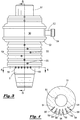
- FIG. 3 depicts a side view of fluid communication swivel assembly 50 of the present invention.
- Mandrel 51 comprises a substantially tubular body having a central longitudinal bore 61 (not shown in FIG. 3 ).
- Mandrel 51 supports flow ring housing 52 having side inlet sub 53 with threaded connection 54.
- Flow ring housing 52 comprises an outer housing defining a closed system for contained flow of drilling mud, cement, slurry, and/or other fluids into cement head 10 via inlet sub 53.
- flow ring housing 52 remains static while mandrel 51 is capable of rotation about its central longitudinal axis.
- Flow ring housing 52 permits the transfer of fluids pumped into side inlet sub 53 to mandrel 51, even during rotation, via a series sealed chambers and drilled bores described in detail below. Still referring to FIG. 3 , a plurality of static ports 55 are provided along the length of fluid communication lower body member 59 assembly. Additionally, a plurality of ports 56 are provided in mandrel 51. In the preferred embodiment, ports 56 are linearly aligned.
- FIG. 5 depicts a side sectional view of fluid communication swivel assembly 50 along line 5-5 of FIG. 3 .
- Flow ring housing 52 has central bore 57 and internal chamber 58 in fluid communication with flow bore 53a of side inlet sub 53.
- Mandrel 51 having central bore 61 is received within bore 57 of flow ring housing 52, and is capable of rotating about its longitudinal axis.
- a plurality of sealing elements 69 are disposed above and below chamber 58, and provide a pressure seal between mandrel 51 and flow ring housing 52.
- sealing elements 69 comprise elastomeric seals.
- a plurality of ports 60 extend through mandrel 51 and permit fluid communication between chamber 58 and central bore 61 of mandrel 51.
- Fluid such as, for example, drilling mud or cement slurry
- Fluid can be pumped through flow bore 53a of side inlet sub 53, into chamber 58, through bores 60, and into central bore 61 of mandrel 51.
- fluid can be pumped through fluid communication swivel assembly 10 when mandrel 51 is static, or when said mandrel 51 is rotating about its central longitudinal axis within flow ring housing 52.
- fluid communication swivel assembly 50 also facilitates fluid transfer, during static or rotating operations, from a fluid power pump (such as, for example, a hydraulic pump) to fluid-driven motors used to remotely operate the present invention.
- a fluid power pump such as, for example, a hydraulic pump
- Hoses or other conduits connect ports 55 with one or more fluid power pumps utilized in connection with lifting cement head 10 of the present invention.
- a plurality of transverse bores 62 extend from ports 55 through lower body member 59.
- a plurality of recessed grooves 63 extends around the outer circumference of mandrel 51; each such recessed groove 63 is aligned with a transverse bore 62.
- At least one communication bore 64 extends from each such transverse bore 62 through the body of mandrel 51 (substantially parallel to central bore 61 of mandrel 51) and exits mandrel 51; each such communication bore 64 terminates at a bore 56.
- Sealing elements 65 are disposed on the sides of each recessed groove 63 in order to provide a fluid seal between fluid communication swivel ring housing 52 and mandrel 51.
- FIG. 4 depicts a sectional view of fluid communication swivel assembly 51 along line 4-4 of FIG. 3 .
- Mandrel 51 has central longitudinal bore 61 extending therethrough.
- a plurality of ports 56 is provided.
- Each of said ports 56 are connected to a communication bore 64.
- each of said bores 64 in turn extends through mandrel 51 a separate isolated recessed groove 63 extending around the outer circumference of mandrel 51.
- each of said recessed grooves in turn, are in fluid communication with a separate transverse bore 62 extending through fluid communication swivel housing 52 and terminating in a static part 55 in lower body member 59 of fluid communication swivel assembly 50.
- a plurality of hoses connect to ports 56 in mandrel 51, and extend to fluid-actuated motors and/or other devices connected to lifting cement head 10.
- each of said pin puller assemblies 70 comprises a side-entry retractable pin sub that is used to suspend objects (such as, for example, darts, wiper plugs, balls and the like) within cement head 10.
- Fluid driven motor 71 is a mechanical device used to power an actuator for said pin puller assembly 70.
- observation port 72 is provided and includes a transparent window-like device to visually/physically observe an object being suspended in the pre-drop static stage. This can be especially significant for field personnel that may not have been present during loading of such object. Observation port 72 allows such field personnel to check, inspect, manipulate, record, read and/or test the pre-dropped object on location, which can save rig time by permitting, but not requiring, field-loading of such objects.
- Observation port 72 also allows an observer to insert a tool or instrument to manipulate a pre-loaded object, or to deploy objects directly into the device in the field. Observation port 72 also allows for addition of non-ferrous material, whether obscure, semi-obscure, or transparent, for wireless communication and identification of pre-drop object using magnetic, radio frequency, infrared, or any other communication median. Observation port 72 also allows for addition of fluid monitor sensors that can monitor different variables including, without limitation, resistivity, obscuration, reflection, temperature and/or fluid-specific characteristics. Further, said sensors may be used to trigger automated functions with said onboard motors and valves described herein. A manual override system allows for operation of pin puller assembly 70 if the actuator should fail to work or if the unit is deliberately used in the manual mode.
- Pin pusher assembly 80 comprises a side-entry extendable pin sub that is used to push objects (including, for example, down hole trip activation balls) into central bore of said lifting cement head 10.
- a fluid driven motor 81 is a mechanical device used to power an actuator for each pin pusher assembly 80.
- Pin pusher assembly 80 beneficially has an override system that allows for manual operation of said pin pusher assembly if the actuator should fail to work or if the unit is deliberately used in the manual mode
- Resetting internal passage indicator 90 is provided to indicate passage of objects used downhole (such as, for example, wiper balls, plugs, darts, trip activation balls, etc.) through the bore of said cement head.
- said internal passage indicator 90 provides a signal such as a bright illuminating visual indication and/or a noticeable audible tone.
- resetting internal passage indicator can comprise a mechanical signaling device, such as a flag, a lever moving up or down, a wheel spinning clockwise or counterclockwise, and/or other similar mechanical indicators.
- automated positive passage detection device 91 can also be used to indicate passage of objects used downhole (such as, for example, wiper balls, plugs, darts, trip activation balls, etc.) through the bore of said cement head.
- Valve 92 is provided having an actuator operated by fluid movement that can selectively open and close said valve 92. Valve 92 can be used to isolate flow through the lower bore, and to/from the well or other items situated below cement head 10. Open/close indicator 93 is provided to display to observer(s) whether the valve 92 is fully open or closed which is essential to mitigate equipment damage from flow washout.
- lower connection member 30 has a threaded "pin-end" threaded connection to connect cement head 10 to a workstring, pup joint or any other below item in the string.
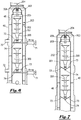
- FIG. 6 depicts a side sectional view of a cage assembly of the present invention
- FIG. 7 depicts a front sectional view of a cage assembly of the present invention.
- Flow around cage assembly 200 comprises a substantially hollow tubular body 201 that is disposed within central bore 48 of central body member 40.
- Tubular body 201 is beneficially supported and aligned within central body member 40 using winged centralizer rails 202.
- Said tubular body 201 is further supported and aligned with the pin puller assembly 70, and observation port 72.
- Darts 300 are disposed in static state within said tubular body 201.
- Said tubular body 201 further comprises top cap 203 that allows some limited flow through said cap and into cage assembly 200.
- Catapult pole 204 is slidably disposed through a bore extending through said top cap 203.
- Catapult pole 204 also has a substantially flat disk 205 at its lower end to prevent top damage to darts 300 (or other objects within cage assembly 200), and to prevent lodging of said dart 300 between catapult pole 204 and the inner surface of cage tubular body 201.
- Biasing spring 206 is provided for energizing catapult pole 204.
- Trap door pairs 73 are hinged and suspended/supported by pin 74, which is in turn connected to pin puller motor 71.
- pin puller motor 71 is actuated to retract pin 74.
- trap door pair 73 is permitted to open, thereby allowing passage of suspended objects such as darts 300.
- the aforementioned apparatus prevents/reduce pre-mature launching of an object around pin 74, and/or lodging of the head bypass (leading surface) of dart 300 between pin 74 and inner surface of cage tubular body 201.
- Pin 74 provides a stable and reliable platform to suspend trap door pairs 73 that in turn support/retain the pre-dropped dart 300.
- Said trap door pairs also act to cup and retain the pre-dropped dart 300 to prevent premature launch of said dart 300 and also reduce the chance for bypass around the pin during high or turbulent flow.
- FIG. 7 depicts a front sectional view of a cage assembly of the present invention showing the head of pin 74. Both doors of trap door pairs 73 rest upon pin 74 prior to retracting said pin 74 (using pin puller motor 71) and opening trap doors 73.
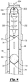
- FIG. 8 depicts a front sectional view of an alternate embodiment of cage assembly of the present invention.
- Flow around cage assembly 200 comprises a substantially hollow tubular body 201 defining an internal space that is disposed within central bore 48 of central body member 40.
- Tubular body 201 is beneficially supported and aligned within central body member 40 using winged centralizer rails 202.
- Said tubular body 201 is further supported and aligned with the pin puller assembly 70, and observation port 72.
- Dart 300 and spherical ball 301 are disposed in static state within said tubular body 201.
- Said tubular body 201 further comprises top cap 203 that allows some limited flow through said cap and into cage assembly 200.
- Catapult pole 204 is slidably disposed through a bore extending through said top cap 203.
- Catapult pole also has a substantially flat disk 205 at its lower end to prevent top damage to darts 300, and to prevent lodging of a dart 300 between catapult pole 204 and the inner surface of cage tubular body 201.
- Trap door pairs 73 are hinged and suspended/supported by pin 74, which is in turn connected to pin puller motor 71.
- pin puller motor 71 is actuated to retract pin 74.
- trap door pair 73 is permitted to swing open, thereby allowing passage of suspended objects (such as darts 300) free downward movement.
- the aforementioned apparatus prevents/reduce premature launching of an object around pin 74, and/or lodging of the head bypass (leading surface) of dart 300 between pin 74 and inner surface of cage tubular body 201.
- Pin 74 provides a stable and reliable platform to suspend trap door pairs 73 that in turn support/retain the pre-dropped dart 300 or spherical ball 301.
- an optional alternator device 401 is provided to convert local mechanical or external energy to electrical energy for onboard power source. Examples are (fluid energy, mechanical rotation, wave energy, solar, sterling engine temperature difference, etc.).
- Wireless communication device 402 is provided to transfer controller information and directions to and from the tool to rig floor, and vice versa.
- Onboard controller 403 is provided for taking in wireless communication signals and transferring such signals to mechanical devices of the present invention. Said device can also facilitate communication with telemetry devices and recording operations.
- Onboard fluid switch 404 is provided for acquiring signals from the controller and diverting fluid to the onboard motors, valves, and other equipment. Non ferrous material is used to withstand internal pressures, yet providing a clear non metallic path for wireless communication.
- Pre-drop communication device 405 is able to read and identify type of object situated within cage assembly 200 inside central body member 40.
- Automated positive passage detection sensor 91 is provided to register passage of an object passing within cement head 10 (such as an object being dropped from cage assembly 200), and is capable of communicating via non ferrous material.
- FIG. 9 depicts an exploded perspective view of dropping mechanism of the present invention.
- Flow around cage assembly 200 comprises a substantially hollow tubular body 201 having a plurality of flow ports 207 that is received and mounted within central bore 48 of central body member 40.
- Tubular body 201 is beneficially supported and aligned within central body member 40 using winged centralizer rails 202.
- Said tubular body 201 is further supported and aligned with the pin puller assemblies 70, and observation ports 72.
- Dart 300 and spherical ball 301 can be loaded and disposed in a static state within said tubular body 201.
- Said tubular body 201 further comprises top cap 203 that allows some limited flow through said cap and into cage assembly 200.
- Catapult pole 204 is slidably disposed through bore 203a extending through said top cap 203.
- Catapult pole 204 also has a substantially flat disk 205 at its lower end to prevent top damage to dart 300 (or other objects within cage assembly 200), and to prevent lodging of said dart 300 between catapult pole 204 and the inner surface of cage tubular body 201.
- Biasing spring 206 is provided for energizing catapult pole 204.
- Catapult pole 204 acts as the main base of the object launching catapult system.
- a form preservation knob protruding from the lower side of disk 205 and fits into the most upper fin/cone of dart 300 or like object that is to be dropped; said form preservation knob prevents fin deformity; if not present the fin could be flatted down by the spring energized catapult which could cause the object to experience undesirable operating conditions such as fluid bypass, fluid being the main vehicle used to deliver the object down the well bore.
- Flow slots 205a are give a higher fluid volume velocity during the displacement phase post object deployment down the well bore.
- Catapult pole 204 assists in object launch, in case of low fluid flow, with a manual cocked-and-loaded spring 206.
- Catapult pole 204 increases velocity of an object being launched and moves such object into the flow path.
- Disk 205 substantially fills the internal diameter of tubular body 201, but has free, reciprocating movement which prevents the top of a pre-dropped object from moving upward and attempting to move by catapult pole 204 that could cause lodging of said object between catapult pole 204 and the inner surface of tubular body 201 as a result of upward/reverse flow or downward plunging during the activation of the catapult mechanism.
- FIG. 10 depicts a sectional view of the lifting cement head 100 of the present apparatus utilized in connection cementing operations on a drilling rig.
- Cement head assembly 100 is provided, either with or without a main flow swivel or side entry sub, and connected to a top drive assembly of a drilling rig.
- a remote controlled valve is at the upper part of the assembly in line with the work string, adjacent is a remote transfer device for fluid communication.
- At least one remote controlled release mechanism and ball drop mechanism that are provided.
- a self- resetting tattletale device alerts operators that an object has passed thru the lower sub and is traveling down hole.
- At least one remote controlled valve is provided at or near the lower extent of cement head assembly 100.
- components of cement head assembly 100 that require movement or actuation can be beneficially operated using a remote control system.
- a remote control system comprises a series of fluid communication hoses/lines.
- other means of remote control can be utilized including, without limitation, fiber optics, infrared, sound waves, radio frequency, blue tooth technology, laser, ultrasound, pressure pulses, magnetic and/or other remote control technology.
- control and monitoring can be accomplished by fluid pulses, hydraulic pressures, wave pulses, ultrasonic pulses or acoustic waves.
- Valves that require or are expected to be fully open or fully closed during operation beneficially include indicators to signal whether such valves are in a fully open or fully closed position.
- Electronic or mechanical monitoring devices can be used to monitor multiple variables during operation of cement head assembly 100, such as force/torque on the assembly, heat, pressure, rotations, RPM, and/or other beneficial data.
- Cement head 100 may also beneficially permit the conversion of mechanical energy (by way of illustration, but not limitation, from fluid flow, tool movement or rotation) into electrical energy for use as an onboard power source.
- said onboard power source may be derived from external elements such as solar power, wave energy, or wind power.
Landscapes
- Life Sciences & Earth Sciences (AREA)
- Engineering & Computer Science (AREA)
- Geology (AREA)
- Mining & Mineral Resources (AREA)
- Physics & Mathematics (AREA)
- Environmental & Geological Engineering (AREA)
- Fluid Mechanics (AREA)
- General Life Sciences & Earth Sciences (AREA)
- Geochemistry & Mineralogy (AREA)
- Earth Drilling (AREA)
Applications Claiming Priority (3)
| Application Number | Priority Date | Filing Date | Title |
|---|---|---|---|
| US20565009P | 2009-01-22 | 2009-01-22 | |
| EP10733880.8A EP2389497B1 (fr) | 2009-01-22 | 2010-01-22 | Appareil et procédé de réalisation d'opérations de cimentation |
| PCT/US2010/021758 WO2010085617A1 (fr) | 2009-01-22 | 2010-01-22 | Appareil et procédé de réalisation d'opérations de cimentation |
Related Parent Applications (2)
| Application Number | Title | Priority Date | Filing Date |
|---|---|---|---|
| EP10733880.8A Division-Into EP2389497B1 (fr) | 2009-01-22 | 2010-01-22 | Appareil et procédé de réalisation d'opérations de cimentation |
| EP10733880.8A Division EP2389497B1 (fr) | 2009-01-22 | 2010-01-22 | Appareil et procédé de réalisation d'opérations de cimentation |
Publications (2)
| Publication Number | Publication Date |
|---|---|
| EP3358128A1 true EP3358128A1 (fr) | 2018-08-08 |
| EP3358128B1 EP3358128B1 (fr) | 2020-02-19 |
Family
ID=42356211
Family Applications (2)
| Application Number | Title | Priority Date | Filing Date |
|---|---|---|---|
| EP10733880.8A Active EP2389497B1 (fr) | 2009-01-22 | 2010-01-22 | Appareil et procédé de réalisation d'opérations de cimentation |
| EP18159005.0A Active EP3358128B1 (fr) | 2009-01-22 | 2010-01-22 | Procédé permettant d'effectuer des opérations de cimentation |
Family Applications Before (1)
| Application Number | Title | Priority Date | Filing Date |
|---|---|---|---|
| EP10733880.8A Active EP2389497B1 (fr) | 2009-01-22 | 2010-01-22 | Appareil et procédé de réalisation d'opérations de cimentation |
Country Status (6)
| Country | Link |
|---|---|
| US (2) | US9212531B2 (fr) |
| EP (2) | EP2389497B1 (fr) |
| AU (2) | AU2010206700B2 (fr) |
| BR (1) | BRPI1005289B1 (fr) |
| NO (1) | NO2389497T3 (fr) |
| WO (1) | WO2010085617A1 (fr) |
Families Citing this family (44)
| Publication number | Priority date | Publication date | Assignee | Title |
|---|---|---|---|---|
| DK2450524T3 (en) | 2007-12-12 | 2015-09-28 | Weatherford Technology Holdings Llc | Upper drive |
| BRPI1005289B1 (pt) * | 2009-01-22 | 2019-09-10 | Blackhawk Specialty Tools Llc | cabeça de cimentar |
| US8887799B2 (en) * | 2010-03-03 | 2014-11-18 | Blackhawk Specialty Tools, Llc | Tattle-tale apparatus |
| US8720559B2 (en) * | 2010-12-01 | 2014-05-13 | Baker Hughes Incorporated | Cementing method and apparatus for use with running string having an obstruction |
| US9739111B2 (en) | 2011-05-05 | 2017-08-22 | Oil States Energy Services, L.L.C. | Controlled aperture ball drop |
| US8636055B2 (en) | 2011-05-05 | 2014-01-28 | Oil States Energy Services, L.L.C. | Controlled aperture ball drop |
| US8910707B2 (en) | 2011-05-17 | 2014-12-16 | Klimack Holdings Inc. | Cement head |
| CA2975946C (fr) | 2013-06-07 | 2020-07-14 | Ge Oil & Gas Canada Inc. | Methode d'exploitation d'un trou de forage |
| US9528346B2 (en) | 2013-11-18 | 2016-12-27 | Weatherford Technology Holdings, Llc | Telemetry operated ball release system |
| US9777569B2 (en) | 2013-11-18 | 2017-10-03 | Weatherford Technology Holdings, Llc | Running tool |
| US9428998B2 (en) | 2013-11-18 | 2016-08-30 | Weatherford Technology Holdings, Llc | Telemetry operated setting tool |
| US9523258B2 (en) | 2013-11-18 | 2016-12-20 | Weatherford Technology Holdings, Llc | Telemetry operated cementing plug release system |
| CA2891750A1 (fr) * | 2014-05-21 | 2015-11-21 | Weatherford/Lamb, Inc. | Detecteur de pointe pour cimentation de tubage de puits de forage |
| CN104029166A (zh) * | 2014-06-18 | 2014-09-10 | 无锡吉兴汽车声学部件科技有限公司 | 乘用车模具拔销器机构 |
| GB201511929D0 (en) * | 2015-07-08 | 2015-08-19 | Statoil Petroleum As | Apparatus for monitoring flows in an oil and gas installation |
| US10626683B2 (en) | 2015-08-11 | 2020-04-21 | Weatherford Technology Holdings, Llc | Tool identification |
| US10465457B2 (en) | 2015-08-11 | 2019-11-05 | Weatherford Technology Holdings, Llc | Tool detection and alignment for tool installation |
| AU2016309001B2 (en) | 2015-08-20 | 2021-11-11 | Weatherford Technology Holdings, Llc | Top drive torque measurement device |
| US10323484B2 (en) | 2015-09-04 | 2019-06-18 | Weatherford Technology Holdings, Llc | Combined multi-coupler for a top drive and a method for using the same for constructing a wellbore |
| WO2017044482A1 (fr) | 2015-09-08 | 2017-03-16 | Weatherford Technology Holdings, Llc | Groupe électrogène pour unité d'entraînement supérieure |
| US10590744B2 (en) | 2015-09-10 | 2020-03-17 | Weatherford Technology Holdings, Llc | Modular connection system for top drive |
| US10167671B2 (en) | 2016-01-22 | 2019-01-01 | Weatherford Technology Holdings, Llc | Power supply for a top drive |
| US11162309B2 (en) | 2016-01-25 | 2021-11-02 | Weatherford Technology Holdings, Llc | Compensated top drive unit and elevator links |
| US10704364B2 (en) | 2017-02-27 | 2020-07-07 | Weatherford Technology Holdings, Llc | Coupler with threaded connection for pipe handler |
| US10954753B2 (en) | 2017-02-28 | 2021-03-23 | Weatherford Technology Holdings, Llc | Tool coupler with rotating coupling method for top drive |
| US11131151B2 (en) | 2017-03-02 | 2021-09-28 | Weatherford Technology Holdings, Llc | Tool coupler with sliding coupling members for top drive |
| US10480247B2 (en) | 2017-03-02 | 2019-11-19 | Weatherford Technology Holdings, Llc | Combined multi-coupler with rotating fixations for top drive |
| US10443326B2 (en) | 2017-03-09 | 2019-10-15 | Weatherford Technology Holdings, Llc | Combined multi-coupler |
| US10247246B2 (en) | 2017-03-13 | 2019-04-02 | Weatherford Technology Holdings, Llc | Tool coupler with threaded connection for top drive |
| US10711574B2 (en) | 2017-05-26 | 2020-07-14 | Weatherford Technology Holdings, Llc | Interchangeable swivel combined multicoupler |
| US10526852B2 (en) | 2017-06-19 | 2020-01-07 | Weatherford Technology Holdings, Llc | Combined multi-coupler with locking clamp connection for top drive |
| US10544631B2 (en) | 2017-06-19 | 2020-01-28 | Weatherford Technology Holdings, Llc | Combined multi-coupler for top drive |
| US10527104B2 (en) | 2017-07-21 | 2020-01-07 | Weatherford Technology Holdings, Llc | Combined multi-coupler for top drive |
| US10355403B2 (en) | 2017-07-21 | 2019-07-16 | Weatherford Technology Holdings, Llc | Tool coupler for use with a top drive |
| US10745978B2 (en) | 2017-08-07 | 2020-08-18 | Weatherford Technology Holdings, Llc | Downhole tool coupling system |
| US10787869B2 (en) | 2017-08-11 | 2020-09-29 | Weatherford Technology Holdings, Llc | Electric tong with onboard hydraulic power unit |
| US11047175B2 (en) | 2017-09-29 | 2021-06-29 | Weatherford Technology Holdings, Llc | Combined multi-coupler with rotating locking method for top drive |
| US11441412B2 (en) | 2017-10-11 | 2022-09-13 | Weatherford Technology Holdings, Llc | Tool coupler with data and signal transfer methods for top drive |
| CN109751007B (zh) * | 2019-02-22 | 2024-11-26 | 杰瑞能源服务有限公司 | 一种远程控制水泥头 |
| CN113924405B (zh) * | 2019-05-09 | 2024-05-14 | 诺伊蒂克技术股份有限公司 | 固井水泥头装置 |
| CN112127832B (zh) * | 2020-09-04 | 2023-01-24 | 中油国家油气钻井装备工程技术研究中心有限公司 | 一体式远程控制水泥头 |
| US11719066B1 (en) * | 2020-09-23 | 2023-08-08 | Rene Castrillon | Oil well rotating cement head |
| CN112878976B (zh) * | 2021-03-02 | 2022-08-02 | 四川申和新材料科技有限公司 | 一种远程遥控暂堵材料的推注系统及应用方法 |
| US12516586B2 (en) | 2024-03-01 | 2026-01-06 | Halliburton Energy Services, Inc. | Cement head flow diverter for tethered cement plug deployment |
Citations (6)
| Publication number | Priority date | Publication date | Assignee | Title |
|---|---|---|---|---|
| EP0500165A1 (fr) * | 1991-02-18 | 1992-08-26 | Pumptech N.V. | Système de libération de lanceurs ("darts") pour tête de cémentation ou outil de fond sous-marin pour puits pétroliers |
| GB2314361A (en) | 1996-06-20 | 1997-12-24 | Baker Hughes Inc | Remote control for a plug-dropping head |
| US5950724A (en) | 1996-09-04 | 1999-09-14 | Giebeler; James F. | Lifting top drive cement head |
| US5960881A (en) * | 1997-04-22 | 1999-10-05 | Jerry P. Allamon | Downhole surge pressure reduction system and method of use |
| US6082451A (en) * | 1995-04-26 | 2000-07-04 | Weatherford/Lamb, Inc. | Wellbore shoe joints and cementing systems |
| US20060027122A1 (en) * | 2004-07-26 | 2006-02-09 | Baker Hughes Incorporated | Cementing head |
Family Cites Families (17)
| Publication number | Priority date | Publication date | Assignee | Title |
|---|---|---|---|---|
| US3863716A (en) * | 1974-04-05 | 1975-02-04 | Halliburton Co | Cementing plug release assist apparatus |
| US4782894A (en) * | 1987-01-12 | 1988-11-08 | Lafleur K K | Cementing plug container with remote control system |
| US5095988A (en) * | 1989-11-15 | 1992-03-17 | Bode Robert E | Plug injection method and apparatus |
| US5236035A (en) * | 1992-02-13 | 1993-08-17 | Halliburton Company | Swivel cementing head with manifold assembly |
| US5443122A (en) * | 1994-08-05 | 1995-08-22 | Halliburton Company | Plug container with fluid pressure responsive cleanout |
| US6182752B1 (en) * | 1998-07-14 | 2001-02-06 | Baker Hughes Incorporated | Multi-port cementing head |
| US6904970B2 (en) * | 2001-08-03 | 2005-06-14 | Smith International, Inc. | Cementing manifold assembly |
| US6634423B2 (en) | 2002-01-16 | 2003-10-21 | Norman B. Giebeler | Lifting top drive remote control cement head |
| US7055611B2 (en) * | 2002-01-31 | 2006-06-06 | Weatherford / Lamb, Inc. | Plug-dropping container for releasing a plug into a wellbore |
| US6672384B2 (en) * | 2002-01-31 | 2004-01-06 | Weatherford/Lamb, Inc. | Plug-dropping container for releasing a plug into a wellbore |
| US6789619B2 (en) * | 2002-04-10 | 2004-09-14 | Bj Services Company | Apparatus and method for detecting the launch of a device in oilfield applications |
| US7607481B2 (en) * | 2007-05-16 | 2009-10-27 | Gulfstream Services, Inc. | Method and apparatus for dropping a pump down plug or ball |
| US8091628B2 (en) * | 2007-05-30 | 2012-01-10 | Smith International, Inc. | Apparatus and method for providing fluid and projectiles to downhole tubulars |
| US8381808B2 (en) * | 2008-10-29 | 2013-02-26 | Halliburton Energy Services, Inc. | Cement head |
| BRPI1005289B1 (pt) * | 2009-01-22 | 2019-09-10 | Blackhawk Specialty Tools Llc | cabeça de cimentar |
| US8561700B1 (en) * | 2009-05-21 | 2013-10-22 | John Phillip Barbee, Jr. | Method and apparatus for cementing while running casing in a well bore |
| US8636067B2 (en) * | 2009-08-28 | 2014-01-28 | Blackhawk Specialty Tools, Llc | Method and apparatus for performing cementing operations on top drive rigs |
-
2010
- 2010-01-22 BR BRPI1005289A patent/BRPI1005289B1/pt active IP Right Grant
- 2010-01-22 EP EP10733880.8A patent/EP2389497B1/fr active Active
- 2010-01-22 US US12/657,558 patent/US9212531B2/en active Active
- 2010-01-22 WO PCT/US2010/021758 patent/WO2010085617A1/fr not_active Ceased
- 2010-01-22 NO NO10733880A patent/NO2389497T3/no unknown
- 2010-01-22 AU AU2010206700A patent/AU2010206700B2/en active Active
- 2010-01-22 EP EP18159005.0A patent/EP3358128B1/fr active Active
-
2015
- 2015-12-07 US US14/961,218 patent/US9605505B2/en active Active
-
2016
- 2016-06-07 AU AU2016203786A patent/AU2016203786B2/en active Active
Patent Citations (6)
| Publication number | Priority date | Publication date | Assignee | Title |
|---|---|---|---|---|
| EP0500165A1 (fr) * | 1991-02-18 | 1992-08-26 | Pumptech N.V. | Système de libération de lanceurs ("darts") pour tête de cémentation ou outil de fond sous-marin pour puits pétroliers |
| US6082451A (en) * | 1995-04-26 | 2000-07-04 | Weatherford/Lamb, Inc. | Wellbore shoe joints and cementing systems |
| GB2314361A (en) | 1996-06-20 | 1997-12-24 | Baker Hughes Inc | Remote control for a plug-dropping head |
| US5950724A (en) | 1996-09-04 | 1999-09-14 | Giebeler; James F. | Lifting top drive cement head |
| US5960881A (en) * | 1997-04-22 | 1999-10-05 | Jerry P. Allamon | Downhole surge pressure reduction system and method of use |
| US20060027122A1 (en) * | 2004-07-26 | 2006-02-09 | Baker Hughes Incorporated | Cementing head |
Also Published As
| Publication number | Publication date |
|---|---|
| US9605505B2 (en) | 2017-03-28 |
| US20100200222A1 (en) | 2010-08-12 |
| AU2016203786A1 (en) | 2016-06-23 |
| NO2389497T3 (fr) | 2018-09-01 |
| US9212531B2 (en) | 2015-12-15 |
| EP2389497B1 (fr) | 2018-04-04 |
| EP2389497A4 (fr) | 2017-03-22 |
| BRPI1005289B1 (pt) | 2019-09-10 |
| EP2389497A1 (fr) | 2011-11-30 |
| EP3358128B1 (fr) | 2020-02-19 |
| AU2010206700B2 (en) | 2016-02-25 |
| AU2010206700A1 (en) | 2011-08-25 |
| BRPI1005289A2 (pt) | 2017-05-02 |
| US20160102521A1 (en) | 2016-04-14 |
| WO2010085617A1 (fr) | 2010-07-29 |
| BRPI1005289A8 (pt) | 2018-04-17 |
| AU2016203786B2 (en) | 2017-10-12 |
Similar Documents
| Publication | Publication Date | Title |
|---|---|---|
| AU2016203786B2 (en) | Method and apparatus for performing cementing operations | |
| US9500060B2 (en) | Method and apparatus for performing cementing operations on top drive rigs | |
| US7980306B2 (en) | Methods, systems and apparatus for coiled tubing testing | |
| US11572754B2 (en) | Freeing stuck subterranean service tools | |
| US8733454B2 (en) | Elevator grip assurance | |
| CN111133169A (zh) | 具有下行链路激活的内部和外部井下结构 | |
| JPH08511839A (ja) | ワイヤーライン切離し装置及び切離し方法 | |
| BR112019015572A2 (pt) | Aparelho para formar pelo menos uma parte de um sistema de produção para um furo do poço, e uma linha para e método de realizar uma operação para ajustar um tampão de cimento em um furo do poço | |
| EP3058172B1 (fr) | Systèmes et procédés de suivi de la position d'un projectile de fond | |
| US10036222B2 (en) | Bottom hole assembly retrieval for casing-while-drilling operations using a tethered float valve | |
| US7246663B2 (en) | Positive engagement indicator for wireline fishing operations | |
| US12338734B1 (en) | Low emission multi-zone hydrocarbon reservoir testing | |
| US11346170B2 (en) | Method and apparatus of intelligent downhole multi-function inflatable system for oil and gas wells | |
| US20130292135A1 (en) | Method and Apparatus for Launching Objects in Dual Gradient Systems | |
| MXPA06005494A (es) | Aparato y metodo para obtener muestras de fondo de pozo |
Legal Events
| Date | Code | Title | Description |
|---|---|---|---|
| PUAI | Public reference made under article 153(3) epc to a published international application that has entered the european phase |
Free format text: ORIGINAL CODE: 0009012 |
|
| STAA | Information on the status of an ep patent application or granted ep patent |
Free format text: STATUS: THE APPLICATION HAS BEEN PUBLISHED |
|
| AC | Divisional application: reference to earlier application |
Ref document number: 2389497 Country of ref document: EP Kind code of ref document: P |
|
| AK | Designated contracting states |
Kind code of ref document: A1 Designated state(s): AT BE BG CH CY CZ DE DK EE ES FI FR GB GR HR HU IE IS IT LI LT LU LV MC MK MT NL NO PL PT RO SE SI SK SM TR |
|
| STAA | Information on the status of an ep patent application or granted ep patent |
Free format text: STATUS: REQUEST FOR EXAMINATION WAS MADE |
|
| 17P | Request for examination filed |
Effective date: 20190129 |
|
| STAA | Information on the status of an ep patent application or granted ep patent |
Free format text: STATUS: EXAMINATION IS IN PROGRESS |
|
| 17Q | First examination report despatched |
Effective date: 20190703 |
|
| GRAP | Despatch of communication of intention to grant a patent |
Free format text: ORIGINAL CODE: EPIDOSNIGR1 |
|
| STAA | Information on the status of an ep patent application or granted ep patent |
Free format text: STATUS: GRANT OF PATENT IS INTENDED |
|
| INTG | Intention to grant announced |
Effective date: 20190920 |
|
| GRAS | Grant fee paid |
Free format text: ORIGINAL CODE: EPIDOSNIGR3 |
|
| GRAA | (expected) grant |
Free format text: ORIGINAL CODE: 0009210 |
|
| STAA | Information on the status of an ep patent application or granted ep patent |
Free format text: STATUS: THE PATENT HAS BEEN GRANTED |
|
| AC | Divisional application: reference to earlier application |
Ref document number: 2389497 Country of ref document: EP Kind code of ref document: P |
|
| AK | Designated contracting states |
Kind code of ref document: B1 Designated state(s): AT BE BG CH CY CZ DE DK EE ES FI FR GB GR HR HU IE IS IT LI LT LU LV MC MK MT NL NO PL PT RO SE SI SK SM TR |
|
| REG | Reference to a national code |
Ref country code: CH Ref legal event code: EP |
|
| REG | Reference to a national code |
Ref country code: DE Ref legal event code: R096 Ref document number: 602010063210 Country of ref document: DE |
|
| REG | Reference to a national code |
Ref country code: AT Ref legal event code: REF Ref document number: 1235170 Country of ref document: AT Kind code of ref document: T Effective date: 20200315 |
|
| REG | Reference to a national code |
Ref country code: IE Ref legal event code: FG4D |
|
| REG | Reference to a national code |
Ref country code: NL Ref legal event code: FP |
|
| REG | Reference to a national code |
Ref country code: NO Ref legal event code: T2 Effective date: 20200219 |
|
| PG25 | Lapsed in a contracting state [announced via postgrant information from national office to epo] |
Ref country code: FI Free format text: LAPSE BECAUSE OF FAILURE TO SUBMIT A TRANSLATION OF THE DESCRIPTION OR TO PAY THE FEE WITHIN THE PRESCRIBED TIME-LIMIT Effective date: 20200219 |
|
| REG | Reference to a national code |
Ref country code: LT Ref legal event code: MG4D |
|
| PG25 | Lapsed in a contracting state [announced via postgrant information from national office to epo] |
Ref country code: IS Free format text: LAPSE BECAUSE OF FAILURE TO SUBMIT A TRANSLATION OF THE DESCRIPTION OR TO PAY THE FEE WITHIN THE PRESCRIBED TIME-LIMIT Effective date: 20200619 Ref country code: SE Free format text: LAPSE BECAUSE OF FAILURE TO SUBMIT A TRANSLATION OF THE DESCRIPTION OR TO PAY THE FEE WITHIN THE PRESCRIBED TIME-LIMIT Effective date: 20200219 Ref country code: LV Free format text: LAPSE BECAUSE OF FAILURE TO SUBMIT A TRANSLATION OF THE DESCRIPTION OR TO PAY THE FEE WITHIN THE PRESCRIBED TIME-LIMIT Effective date: 20200219 Ref country code: BG Free format text: LAPSE BECAUSE OF FAILURE TO SUBMIT A TRANSLATION OF THE DESCRIPTION OR TO PAY THE FEE WITHIN THE PRESCRIBED TIME-LIMIT Effective date: 20200519 Ref country code: GR Free format text: LAPSE BECAUSE OF FAILURE TO SUBMIT A TRANSLATION OF THE DESCRIPTION OR TO PAY THE FEE WITHIN THE PRESCRIBED TIME-LIMIT Effective date: 20200520 Ref country code: HR Free format text: LAPSE BECAUSE OF FAILURE TO SUBMIT A TRANSLATION OF THE DESCRIPTION OR TO PAY THE FEE WITHIN THE PRESCRIBED TIME-LIMIT Effective date: 20200219 |
|
| PG25 | Lapsed in a contracting state [announced via postgrant information from national office to epo] |
Ref country code: ES Free format text: LAPSE BECAUSE OF FAILURE TO SUBMIT A TRANSLATION OF THE DESCRIPTION OR TO PAY THE FEE WITHIN THE PRESCRIBED TIME-LIMIT Effective date: 20200219 Ref country code: LT Free format text: LAPSE BECAUSE OF FAILURE TO SUBMIT A TRANSLATION OF THE DESCRIPTION OR TO PAY THE FEE WITHIN THE PRESCRIBED TIME-LIMIT Effective date: 20200219 Ref country code: DK Free format text: LAPSE BECAUSE OF FAILURE TO SUBMIT A TRANSLATION OF THE DESCRIPTION OR TO PAY THE FEE WITHIN THE PRESCRIBED TIME-LIMIT Effective date: 20200219 Ref country code: SM Free format text: LAPSE BECAUSE OF FAILURE TO SUBMIT A TRANSLATION OF THE DESCRIPTION OR TO PAY THE FEE WITHIN THE PRESCRIBED TIME-LIMIT Effective date: 20200219 Ref country code: EE Free format text: LAPSE BECAUSE OF FAILURE TO SUBMIT A TRANSLATION OF THE DESCRIPTION OR TO PAY THE FEE WITHIN THE PRESCRIBED TIME-LIMIT Effective date: 20200219 Ref country code: CZ Free format text: LAPSE BECAUSE OF FAILURE TO SUBMIT A TRANSLATION OF THE DESCRIPTION OR TO PAY THE FEE WITHIN THE PRESCRIBED TIME-LIMIT Effective date: 20200219 Ref country code: RO Free format text: LAPSE BECAUSE OF FAILURE TO SUBMIT A TRANSLATION OF THE DESCRIPTION OR TO PAY THE FEE WITHIN THE PRESCRIBED TIME-LIMIT Effective date: 20200219 Ref country code: PT Free format text: LAPSE BECAUSE OF FAILURE TO SUBMIT A TRANSLATION OF THE DESCRIPTION OR TO PAY THE FEE WITHIN THE PRESCRIBED TIME-LIMIT Effective date: 20200712 Ref country code: SK Free format text: LAPSE BECAUSE OF FAILURE TO SUBMIT A TRANSLATION OF THE DESCRIPTION OR TO PAY THE FEE WITHIN THE PRESCRIBED TIME-LIMIT Effective date: 20200219 |
|
| REG | Reference to a national code |
Ref country code: AT Ref legal event code: MK05 Ref document number: 1235170 Country of ref document: AT Kind code of ref document: T Effective date: 20200219 |
|
| REG | Reference to a national code |
Ref country code: DE Ref legal event code: R097 Ref document number: 602010063210 Country of ref document: DE |
|
| PLBE | No opposition filed within time limit |
Free format text: ORIGINAL CODE: 0009261 |
|
| STAA | Information on the status of an ep patent application or granted ep patent |
Free format text: STATUS: NO OPPOSITION FILED WITHIN TIME LIMIT |
|
| 26N | No opposition filed |
Effective date: 20201120 |
|
| PG25 | Lapsed in a contracting state [announced via postgrant information from national office to epo] |
Ref country code: IT Free format text: LAPSE BECAUSE OF FAILURE TO SUBMIT A TRANSLATION OF THE DESCRIPTION OR TO PAY THE FEE WITHIN THE PRESCRIBED TIME-LIMIT Effective date: 20200219 Ref country code: AT Free format text: LAPSE BECAUSE OF FAILURE TO SUBMIT A TRANSLATION OF THE DESCRIPTION OR TO PAY THE FEE WITHIN THE PRESCRIBED TIME-LIMIT Effective date: 20200219 |
|
| PG25 | Lapsed in a contracting state [announced via postgrant information from national office to epo] |
Ref country code: SI Free format text: LAPSE BECAUSE OF FAILURE TO SUBMIT A TRANSLATION OF THE DESCRIPTION OR TO PAY THE FEE WITHIN THE PRESCRIBED TIME-LIMIT Effective date: 20200219 Ref country code: PL Free format text: LAPSE BECAUSE OF FAILURE TO SUBMIT A TRANSLATION OF THE DESCRIPTION OR TO PAY THE FEE WITHIN THE PRESCRIBED TIME-LIMIT Effective date: 20200219 |
|
| REG | Reference to a national code |
Ref country code: NO Ref legal event code: CHAD Owner name: FRANK'S INTERNATIONAL, US |
|
| REG | Reference to a national code |
Ref country code: DE Ref legal event code: R119 Ref document number: 602010063210 Country of ref document: DE |
|
| REG | Reference to a national code |
Ref country code: GB Ref legal event code: 732E Free format text: REGISTERED BETWEEN 20210708 AND 20210714 |
|
| PG25 | Lapsed in a contracting state [announced via postgrant information from national office to epo] |
Ref country code: MC Free format text: LAPSE BECAUSE OF FAILURE TO SUBMIT A TRANSLATION OF THE DESCRIPTION OR TO PAY THE FEE WITHIN THE PRESCRIBED TIME-LIMIT Effective date: 20200219 |
|
| REG | Reference to a national code |
Ref country code: CH Ref legal event code: PL |
|
| PG25 | Lapsed in a contracting state [announced via postgrant information from national office to epo] |
Ref country code: LU Free format text: LAPSE BECAUSE OF NON-PAYMENT OF DUE FEES Effective date: 20210122 |
|
| REG | Reference to a national code |
Ref country code: BE Ref legal event code: MM Effective date: 20210131 |
|
| PG25 | Lapsed in a contracting state [announced via postgrant information from national office to epo] |
Ref country code: FR Free format text: LAPSE BECAUSE OF NON-PAYMENT OF DUE FEES Effective date: 20210131 |
|
| REG | Reference to a national code |
Ref country code: NL Ref legal event code: PD Owner name: FRANK'S INTERNATIONAL, LLC; US Free format text: DETAILS ASSIGNMENT: CHANGE OF OWNER(S), ASSIGNMENT; FORMER OWNER NAME: BLACKHAWK SPECIALTY TOOLS, LLC Effective date: 20211008 |
|
| PG25 | Lapsed in a contracting state [announced via postgrant information from national office to epo] |
Ref country code: LI Free format text: LAPSE BECAUSE OF NON-PAYMENT OF DUE FEES Effective date: 20210131 Ref country code: DE Free format text: LAPSE BECAUSE OF NON-PAYMENT OF DUE FEES Effective date: 20210803 Ref country code: CH Free format text: LAPSE BECAUSE OF NON-PAYMENT OF DUE FEES Effective date: 20210131 |
|
| PG25 | Lapsed in a contracting state [announced via postgrant information from national office to epo] |
Ref country code: IE Free format text: LAPSE BECAUSE OF NON-PAYMENT OF DUE FEES Effective date: 20210122 |
|
| PG25 | Lapsed in a contracting state [announced via postgrant information from national office to epo] |
Ref country code: BE Free format text: LAPSE BECAUSE OF NON-PAYMENT OF DUE FEES Effective date: 20210131 |
|
| PG25 | Lapsed in a contracting state [announced via postgrant information from national office to epo] |
Ref country code: CY Free format text: LAPSE BECAUSE OF FAILURE TO SUBMIT A TRANSLATION OF THE DESCRIPTION OR TO PAY THE FEE WITHIN THE PRESCRIBED TIME-LIMIT Effective date: 20200219 |
|
| P01 | Opt-out of the competence of the unified patent court (upc) registered |
Effective date: 20230512 |
|
| PG25 | Lapsed in a contracting state [announced via postgrant information from national office to epo] |
Ref country code: HU Free format text: LAPSE BECAUSE OF FAILURE TO SUBMIT A TRANSLATION OF THE DESCRIPTION OR TO PAY THE FEE WITHIN THE PRESCRIBED TIME-LIMIT; INVALID AB INITIO Effective date: 20100122 |
|
| PG25 | Lapsed in a contracting state [announced via postgrant information from national office to epo] |
Ref country code: MK Free format text: LAPSE BECAUSE OF FAILURE TO SUBMIT A TRANSLATION OF THE DESCRIPTION OR TO PAY THE FEE WITHIN THE PRESCRIBED TIME-LIMIT Effective date: 20200219 |
|
| PG25 | Lapsed in a contracting state [announced via postgrant information from national office to epo] |
Ref country code: MT Free format text: LAPSE BECAUSE OF FAILURE TO SUBMIT A TRANSLATION OF THE DESCRIPTION OR TO PAY THE FEE WITHIN THE PRESCRIBED TIME-LIMIT Effective date: 20200219 |
|
| PG25 | Lapsed in a contracting state [announced via postgrant information from national office to epo] |
Ref country code: TR Free format text: LAPSE BECAUSE OF FAILURE TO SUBMIT A TRANSLATION OF THE DESCRIPTION OR TO PAY THE FEE WITHIN THE PRESCRIBED TIME-LIMIT Effective date: 20200219 |
|
| PGFP | Annual fee paid to national office [announced via postgrant information from national office to epo] |
Ref country code: GB Payment date: 20251204 Year of fee payment: 17 |
|
| PGFP | Annual fee paid to national office [announced via postgrant information from national office to epo] |
Ref country code: NL Payment date: 20251215 Year of fee payment: 17 |
|
| PGFP | Annual fee paid to national office [announced via postgrant information from national office to epo] |
Ref country code: NO Payment date: 20260109 Year of fee payment: 17 |