EP3358189A1 - Paire de rotors pour bloc de compresseur d'une visseuse - Google Patents
Paire de rotors pour bloc de compresseur d'une visseuse Download PDFInfo
- Publication number
- EP3358189A1 EP3358189A1 EP18163593.9A EP18163593A EP3358189A1 EP 3358189 A1 EP3358189 A1 EP 3358189A1 EP 18163593 A EP18163593 A EP 18163593A EP 3358189 A1 EP3358189 A1 EP 3358189A1
- Authority
- EP
- European Patent Office
- Prior art keywords
- rotor
- tooth
- axis
- und
- radius
- Prior art date
- Legal status (The legal status is an assumption and is not a legal conclusion. Google has not performed a legal analysis and makes no representation as to the accuracy of the status listed.)
- Granted
Links
Images


Classifications
-
- F—MECHANICAL ENGINEERING; LIGHTING; HEATING; WEAPONS; BLASTING
- F04—POSITIVE - DISPLACEMENT MACHINES FOR LIQUIDS; PUMPS FOR LIQUIDS OR ELASTIC FLUIDS
- F04C—ROTARY-PISTON, OR OSCILLATING-PISTON, POSITIVE-DISPLACEMENT MACHINES FOR LIQUIDS; ROTARY-PISTON, OR OSCILLATING-PISTON, POSITIVE-DISPLACEMENT PUMPS
- F04C18/00—Rotary-piston pumps specially adapted for elastic fluids
- F04C18/08—Rotary-piston pumps specially adapted for elastic fluids of intermeshing-engagement type, i.e. with engagement of co-operating members similar to that of toothed gearing
- F04C18/082—Details specially related to intermeshing engagement type pumps
- F04C18/084—Toothed wheels
-
- F—MECHANICAL ENGINEERING; LIGHTING; HEATING; WEAPONS; BLASTING
- F01—MACHINES OR ENGINES IN GENERAL; ENGINE PLANTS IN GENERAL; STEAM ENGINES
- F01C—ROTARY-PISTON OR OSCILLATING-PISTON MACHINES OR ENGINES
- F01C1/00—Rotary-piston machines or engines
- F01C1/08—Rotary-piston machines or engines of intermeshing engagement type, i.e. with engagement of co- operating members similar to that of toothed gearing
- F01C1/082—Details specially related to intermeshing engagement type machines or engines
- F01C1/084—Toothed wheels
-
- F—MECHANICAL ENGINEERING; LIGHTING; HEATING; WEAPONS; BLASTING
- F01—MACHINES OR ENGINES IN GENERAL; ENGINE PLANTS IN GENERAL; STEAM ENGINES
- F01C—ROTARY-PISTON OR OSCILLATING-PISTON MACHINES OR ENGINES
- F01C1/00—Rotary-piston machines or engines
- F01C1/08—Rotary-piston machines or engines of intermeshing engagement type, i.e. with engagement of co- operating members similar to that of toothed gearing
- F01C1/12—Rotary-piston machines or engines of intermeshing engagement type, i.e. with engagement of co- operating members similar to that of toothed gearing of other than internal-axis type
- F01C1/14—Rotary-piston machines or engines of intermeshing engagement type, i.e. with engagement of co- operating members similar to that of toothed gearing of other than internal-axis type with toothed rotary pistons
- F01C1/16—Rotary-piston machines or engines of intermeshing engagement type, i.e. with engagement of co- operating members similar to that of toothed gearing of other than internal-axis type with toothed rotary pistons with helical teeth, e.g. chevron-shaped, screw type
-
- F—MECHANICAL ENGINEERING; LIGHTING; HEATING; WEAPONS; BLASTING
- F04—POSITIVE - DISPLACEMENT MACHINES FOR LIQUIDS; PUMPS FOR LIQUIDS OR ELASTIC FLUIDS
- F04C—ROTARY-PISTON, OR OSCILLATING-PISTON, POSITIVE-DISPLACEMENT MACHINES FOR LIQUIDS; ROTARY-PISTON, OR OSCILLATING-PISTON, POSITIVE-DISPLACEMENT PUMPS
- F04C18/00—Rotary-piston pumps specially adapted for elastic fluids
- F04C18/08—Rotary-piston pumps specially adapted for elastic fluids of intermeshing-engagement type, i.e. with engagement of co-operating members similar to that of toothed gearing
- F04C18/12—Rotary-piston pumps specially adapted for elastic fluids of intermeshing-engagement type, i.e. with engagement of co-operating members similar to that of toothed gearing of other than internal-axis type
- F04C18/14—Rotary-piston pumps specially adapted for elastic fluids of intermeshing-engagement type, i.e. with engagement of co-operating members similar to that of toothed gearing of other than internal-axis type with toothed rotary pistons
- F04C18/16—Rotary-piston pumps specially adapted for elastic fluids of intermeshing-engagement type, i.e. with engagement of co-operating members similar to that of toothed gearing of other than internal-axis type with toothed rotary pistons with helical teeth, e.g. chevron-shaped, screw type
-
- F—MECHANICAL ENGINEERING; LIGHTING; HEATING; WEAPONS; BLASTING
- F04—POSITIVE - DISPLACEMENT MACHINES FOR LIQUIDS; PUMPS FOR LIQUIDS OR ELASTIC FLUIDS
- F04C—ROTARY-PISTON, OR OSCILLATING-PISTON, POSITIVE-DISPLACEMENT MACHINES FOR LIQUIDS; ROTARY-PISTON, OR OSCILLATING-PISTON, POSITIVE-DISPLACEMENT PUMPS
- F04C18/00—Rotary-piston pumps specially adapted for elastic fluids
- F04C18/08—Rotary-piston pumps specially adapted for elastic fluids of intermeshing-engagement type, i.e. with engagement of co-operating members similar to that of toothed gearing
- F04C18/12—Rotary-piston pumps specially adapted for elastic fluids of intermeshing-engagement type, i.e. with engagement of co-operating members similar to that of toothed gearing of other than internal-axis type
- F04C18/14—Rotary-piston pumps specially adapted for elastic fluids of intermeshing-engagement type, i.e. with engagement of co-operating members similar to that of toothed gearing of other than internal-axis type with toothed rotary pistons
- F04C18/20—Rotary-piston pumps specially adapted for elastic fluids of intermeshing-engagement type, i.e. with engagement of co-operating members similar to that of toothed gearing of other than internal-axis type with toothed rotary pistons with dissimilar tooth forms
-
- F—MECHANICAL ENGINEERING; LIGHTING; HEATING; WEAPONS; BLASTING
- F04—POSITIVE - DISPLACEMENT MACHINES FOR LIQUIDS; PUMPS FOR LIQUIDS OR ELASTIC FLUIDS
- F04C—ROTARY-PISTON, OR OSCILLATING-PISTON, POSITIVE-DISPLACEMENT MACHINES FOR LIQUIDS; ROTARY-PISTON, OR OSCILLATING-PISTON, POSITIVE-DISPLACEMENT PUMPS
- F04C2240/00—Components
- F04C2240/20—Rotors
-
- F—MECHANICAL ENGINEERING; LIGHTING; HEATING; WEAPONS; BLASTING
- F04—POSITIVE - DISPLACEMENT MACHINES FOR LIQUIDS; PUMPS FOR LIQUIDS OR ELASTIC FLUIDS
- F04C—ROTARY-PISTON, OR OSCILLATING-PISTON, POSITIVE-DISPLACEMENT MACHINES FOR LIQUIDS; ROTARY-PISTON, OR OSCILLATING-PISTON, POSITIVE-DISPLACEMENT PUMPS
- F04C2240/00—Components
- F04C2240/30—Casings or housings
-
- F—MECHANICAL ENGINEERING; LIGHTING; HEATING; WEAPONS; BLASTING
- F04—POSITIVE - DISPLACEMENT MACHINES FOR LIQUIDS; PUMPS FOR LIQUIDS OR ELASTIC FLUIDS
- F04C—ROTARY-PISTON, OR OSCILLATING-PISTON, POSITIVE-DISPLACEMENT MACHINES FOR LIQUIDS; ROTARY-PISTON, OR OSCILLATING-PISTON, POSITIVE-DISPLACEMENT PUMPS
- F04C2240/00—Components
- F04C2240/60—Shafts
Definitions
- the invention relates to a rotor pair for a compressor block of a screw machine, wherein the rotor pair consists of a main rotor rotating about a first axis and a secondary rotor rotating about a second axis according to the features of claim 1, 9 or 14. Furthermore, the invention relates to a compressor block with a corresponding rotor pair.
- Screw machines whether as screw compressors or as screw expanders, have been in practical use for several decades. Designed as screw compressors, they have forced reciprocating compressors as compressors in many areas. With the principle of the intermeshing screw pair not only gases can be compressed by applying a certain amount of work. The use as a vacuum pump also opens up the use of screw machines to achieve a vacuum. Finally, by passing pressurized gases the other way around, a workload can be generated, so that from pressurized gases by means of the principle of the screw machine and mechanical energy can be obtained.
- Screw machines generally have two shafts arranged parallel to one another, on which, on the one hand, a main rotor and, on the other hand, a secondary rotor are seated. Main rotor and secondary rotor interlock with corresponding helical teeth. Between the gears and one Compressor housing, are included in the main and secondary rotor, a compression space (working chambers) is formed by the tooth space volumes. Starting from a suction area, the working chamber is first closed and then continuously reduced in volume as the main and secondary rotor rotate, so that a compression of the medium occurs. Finally, as the rotation progresses, the working chamber is opened to a pressure window and the medium is ejected into the pressure window.
- screw machines designed as screw compressors differ from Roots blowers which operate without internal compression.
- typical pressure ratios can be between 1.1 and 20, the pressure ratio being the ratio of the final compression pressure to the suction pressure.
- the compression can be done in one or more stages.
- Achievable ultimate pressures can be, for example, in the range of 1.1 bar to 20 bar. Insofar as reference is made to "bar" pressure data at this point or subsequently in the present application, such pressure data relate in each case to absolute pressures.
- Screw machines can be used in addition to the already mentioned function as a vacuum pump or as a screw expander in various fields of technology as a compressor.
- a particularly preferred field of application is in the compression of gases, such as air or inert gases, (helium, nitrogen, ). But it is also possible, although this in particular structurally different requirements, a screw machine for the compression of refrigerants, for example, for air conditioning or refrigeration applications to use.
- gases such as air or inert gases, (helium, nitrogen, ).
- a screw machine for the compression of refrigerants for example, for air conditioning or refrigeration applications to use.
- a fluid-injected compression in particular an oil-injected compression
- screw compressors are sometimes referred to as a screw blower.
- Improvements or optimizations often refer to optimizations of the efficiency as a function of the number of teeth, wrap angle and length / diameter ratio of the rotors. The addition of the incisions in the optimization process can only be found in recent times.
- a short profile gap length should be combined with a small (pressure side) blow hole to minimize internal leakage.
- the two sizes behave in opposite directions. This means that the smaller the blow hole is modeled, the larger the profile gap length inevitably becomes. Conversely, the shorter the profile gap length, the larger the blow hole becomes. This explains Helpertz in his example Dissertation "Method for stochastic optimization of screw rotor profiles", Dortmund, 2003 on page 162 ,
- the requirement for a short profile gap length can be realized in a known manner with a flat running profile with correspondingly smaller relative tread depth of the secondary rotor. Whether a profile is rather flat (low tread depth) or deep (large tread depth) is executed, can be graphically quantified with the so-called "relative tread depth of the secondary rotor", which refers to the difference between the head and root radius on the tip circle radius of the secondary rotor.
- relative tread depth of the secondary rotor refers to the difference between the head and root radius on the tip circle radius of the secondary rotor.
- the larger the value the more compact the compressor block is and, for example more delivery volume than a comparable compressor block with the same external dimensions.
- blow hole area can be kept small by making the head roundings of the profiles small in the face cut. Specifically, this can be effected by a strong curvature in the head region of the leading tooth flank of the secondary rotor and in the head region of the trailing tooth flank of the main rotor. However, the stronger this curvature is, the sooner one gets into production-related boundary areas, since this leads, for example, to high wear on profile cutters and profile grinding wheels in the production of main rotor and secondary rotor.
- blowing holes on the intake side do not have a negative effect on the energy efficiency since they only connect working chambers in the intake region at the same pressure.
- chamber gusset volume Another cause of efficiency-reducing internal leakage is the so-called chamber gusset volume, which can arise in the pressure window when the last working chamber (that is, the working chamber in which the highest pressure prevails) is ejected.
- the working chamber then has no connection to the pressure window from a certain angular position of the rotors. There remains a so-called.
- Chamber gusset volume between the two rotors and the pressure-side housing end wall.
- Compact compressor blocks with a high construction volume utilization are achieved by a large tooth space volume, which in turn depends on the profile depth and the tooth thickness.
- the object of the present invention is to provide a pair of rotors for a compressor block of a screw machine, which is characterized by high operational reliability and reasonable manufacturing costs by high smoothness and a special energy efficiency.
- the rotor geometry is essentially characterized by the shape of the front section and by the rotor length and the wrap angle, cf. " Method for Stochastic Optimization of Screw Rotor Profiles ", Dissertation by Markus Helpertz, Dortmund, 2003, p. 11/12 ,
- secondary rotor or main rotor have a predetermined, often different number per rotor of identically designed teeth.
- the extreme circle drawn through the axis C1 or C2 via the vertices of the teeth is referred to as the tip circle.
- a foot circle is defined in the end section.
- the ribs are referred to as teeth of the rotor.
- the grooves (or recesses) are referred to as tooth gaps.
- the area of the tooth at and above the root defines the tooth profile.
- the contour of the ribs defines the course of the tooth profile.
- foot points F1 and F2 and a vertex F5 are defined.
- the vertex F5 or H5 is defined by the radially outermost point of the tooth profile. If the tooth profile has several points with the same maximum radial distance from the center defined by the axis C1 or C2, ie if the tooth profile follows a circular arc on the top circle at its radially outer end, then the vertex F5 lies exactly in the center of this circular arc. Between two adjacent vertices F5, a tooth space is defined.
- the points closest to the axis C1 or C2 between a considered and the adjacent tooth define foot points F1 and F2.
- foot points F1 and F2 lie on half of this circular arc lying on the root circle
- a pitch circle is defined by the meshing of the main rotor and the secondary rotor both for the secondary rotor and for the main rotor.
- the pitch circle diameters of the main rotor and secondary rotor can be determined with the help of the center distance and the number of teeth ratios.
- tooth space areas between the teeth and the respective top circle KK are defined, namely tooth space area A6 between the profile profile of the secondary rotor NR between two adjacent vertices F5 and the tip circle KK 1 or an area A7 as the tooth gap area between the profile course of the main rotor (HR) between two adjacent vertices H5 and the tip circle KK 2 .
- the tooth profile of the secondary rotor (but also of the main rotor) has a respective tooth flank leading in the direction of rotation and a tooth flank trailing in the direction of rotation.
- the leading tooth flank is designated below by F V
- the trailing tooth flank by F N.
- the trailing tooth flank F N forms a point in its section between tip circle and root circle in which the curvature of the profile of the tooth profile changes. This point is referred to below as F8 and divides the trailing tooth flank F N into a convexly curved portion between F8 and the tip circle and a concavely curved portion between the root circle and F8. Small-scale profile changes, such as by sealing strips or by other local profile transformations are not taken into account in the consideration of the above-described curvature change.
- a wrap angle ⁇ is defined. This wrap angle is the angle by which the end cut is twisted from the suction side to the pressure side rotor end face, cf. also the further explanations in connection with FIG. 8 ,
- the main rotor has a rotor length LHR, which is defined as the distance of a suction-side main rotor rotor end face to a pressure-side main rotor rotor end face.
- the distance between the mutually parallel first axis C1 of the secondary rotor to the second axis C2 of the main rotor is referred to below as the axial distance a.
- the length of the main rotor L HR corresponds to the length of the secondary rotor L NR , whereby the length is also understood as the distance of a suction-side secondary rotor rotor face to a pressure-side slave rotor rotor face in the secondary rotor.
- a rotor length ratio L HR / a is defined, ie a ratio of the rotor length of the main rotor to the axial distance.
- the ratio L HR / a is a measure of the axial dimensioning of the rotor profile.
- the engagement line is as follows: The tooth flanks of the main rotor and secondary rotor touch each other with backlash-free teeth depending on the angular position of the rotors in certain points. These points are called engagement points.
- the geometric location of all engagement points is called the engagement line and can already be calculated in two-dimensional terms from the front section of the rotors, cf. FIG. 7j ,
- the engagement line is divided into two sections in the front-sectional view through the connecting line between the two center points C1 and C2, into a (comparatively short) suction-side section and a (comparatively long) pressure-side section.
- the engagement line can also be extended three-dimensionally and corresponds to the contact line of main rotor and secondary rotor.
- the axial projection of the three-dimensional line of action on the end section plane results in the basis of FIG. 7j illustrated two-dimensional engagement line.
- line of action is used in the literature for both two-dimensional and three-dimensional viewing.
- engagement line is understood to mean, however, the two-dimensional engagement line, that is to say the projection onto the endcut.
- the profile engagement gap is defined as follows: In the real compressor block of a screw machine clearance between the two rotors is present at installation axis distance of main rotor and side rotor.
- the gap between the main rotor and the secondary rotor is referred to as the profile engaging gap and is the locus of any point where the two paired rotors are in contact with each other or the least spaced apart.
- the profile engagement gap Through the profile engagement gap, the compressing and ejecting working chambers are connected to chambers which are still in contact with the suction side. At the profile engagement gap is thus the entire maximum pressure ratio.
- the profile engagement gap already compressed working fluid is transported back to the suction side and thus reduces the efficiency of compaction. Since the profile engagement gap would be the engagement line with backlash-free teeth, the profile engagement gap is also referred to as a "quasi-engagement line".
- Blowholes between working chambers are created by head rounding of the teeth of the profile.
- About blowholes are the working chambers with leading and connected subsequent working chambers, so that (in contrast to the profile engagement gap) at a blow hole rests only the pressure difference from one working chamber to the next working chamber.
- tooth pairings are common in screw machines, for example a rotor pair in which the main rotor 3 and the sub rotor 4 teeth or a rotor pairing, in which the main rotor 4 teeth and the secondary rotor 5 teeth or further a rotor pair geometry, in which the main rotor 5 teeth and the secondary rotor has 6 teeth.
- Rotor pairs or screw machines with different tooth number ratio may be used for different fields of application or purposes.
- rotor pair arrangements having a 4/5 teeth ratio (4 tooth main rotor, 5 teeth secondary rotor) are considered to be a suitable mating for oil injected compression applications in moderate pressure ranges.
- the number of teeth or the number of teeth gives different types of rotor pairings and, as a result, also different types of screw machines, in particular screw compressors.
- the rotor length ratio is formed of the ratio of the rotor length L HR of the main rotor and the center distance a and the rotor length L HR of the main rotor is formed by the distance of a suction-side main rotor rotor face to an opposite pressure-side main rotor rotor face.
- the rotor length ratio of the ratio of the rotor length L HR of the main rotor and the axial distance a is formed and the rotor length L HR of Main rotor is formed by the distance of a suction-side main rotor rotor face to an opposite pressure-side main rotor rotor face.
- the rotor length ratio is formed of the ratio of the rotor length L HR of the main rotor and the center distance a and the rotor length L HR of the main rotor is formed by the distance of a suction-side main rotor rotor face to an opposite pressure-side main rotor rotor face.
- the values for the relative tread depth on the one hand and the ratio of center distance to pitch radius of the secondary rotor on the other hand for the specified teeth-number ratios in the specified advantageous ranges so are the basic requirements for a good side rotor profile or a good interaction of secondary rotor profile and Created main rotor profile, in particular, this is a particularly favorable ratio of Blasloch Structure allows profile gap length.
- the relative tread depth of the secondary rotor is a measure of how deep the profiles are cut. As the tread depth increases, for example, the volume of construction volume increases, but at the expense of the flexural rigidity of the secondary rotor.
- the values given for the rotor length ratio L HR / a and the wrap angle ⁇ HR represent advantageous or expedient values for the respectively indicated tooth-number ratio in order to determine an advantageous rotor pairing in the axial dimension.
- the goal is to combine a small blow hole with a short length of the profile engagement gap.
- the two parameters behave in opposite directions, ie the smaller the blow hole is modeled, the greater the inevitable length of the profile engagement gap. Conversely, the shorter the length of the profile engagement gap, the larger the blow hole becomes.
- a particularly favorable combination of the two parameters is achieved. At the same time a sufficiently high bending stiffness of the secondary rotor is ensured.
- a further preferred embodiment provides that in an end-sectional view between the considered tooth of the secondary rotor (NR) and the respectively adjacent tooth of the secondary rotor, foot points F1 and F2 are defined at the root circle and at the radially outermost point of the tooth a vertex F5, where F1, F2 and F5 a triangle D Z is defined and wherein in a radially outer region of the tooth with its formed between F5 and F2 leading tooth flank F V with a surface A1 and with its trailing formed between F1 and F5 tooth flank F N with a surface A2 via the triangle D Z survives and wherein 8 ⁇ A2 / A1 ⁇ 60 is maintained.
- the tooth part surface A1 on the leading tooth flank F V of the secondary rotor has a significant influence on the blow hole surface.
- the tooth part surface A2 on the trailing tooth flank F N of the secondary rotor has a significant influence on the length of the profile engagement gap, the chamber extension and the secondary rotor torque.
- For the tooth area ratio A2 / A1 there is an advantageous range that allows a good compromise between the length of the profile engagement gap on the one hand and blow hole on the other. With regard to the illustration of the parameters is also on FIG. 7d directed.
- the pair of rotors has a secondary rotor, in which, in a cross-sectional view, between the considered tooth of the secondary rotor (NR) and the respective adjacent tooth of the Maurotors brieflytime-F1 and F2 and at the radially outermost point of the tooth a vertex F5 are defined, wherein by F1, F2 and F5, a triangle D Z is defined and wherein the formed between F5 and F2 leading tooth flank F V in a radially outer region of the tooth with a surface A1 beyond the triangle D Z and in a radially inner region with respect to the triangle D Z recedes with an area A3 and wherein 7.0 ⁇ A3 / A1 ⁇ 35 is maintained.
- FIG. 7d Refer is also made to the FIG. 7d directed.
- the offset angle is always always positive, ie always the offset in the direction of the direction of rotation is given and not contrary.
- the tooth of the secondary rotor is curved in this respect to the direction of rotation of the secondary rotor.
- the offset should be in the range indicated to be favorable to allow a favorable compromise between the blow hole area, the shape of the line of engagement, the length and shape of the profile engagement gap, the minor rotor torque, the flexural stiffness of the rotors, and the chamber thrust into the pressure window.
- Figure 7f directed.
- the trailing tooth flank F N of a tooth of the secondary rotor (NR) formed between F1 and F5 has a convex length portion of at least 45% to at most 95%.
- Preferred dimensions of the female rotor is designed such that in an end section view of the axis C1 of the slave rotor (NR) the tooth profile associated by F5 solid radial line R in one of the leading tooth flank F V surface portion A5, and a trailing tooth flank F N associated surface portion divides A4 and in which 5 ⁇ A 4 / A 5 ⁇ 14 is complied with.
- the tooth profile is limited radially inward toward the axis C1 through the root circle FK 1 .
- the radial ray R divides the tooth profile in such a way that two disjoint surface portions with a total surface area A5, which are assigned to the leading tooth flank F V , arise, cf.
- FIG. 7g If the vertex F5 were to be offset from the leading tooth flank in such a way that the radial ray R not only touched the leading tooth flank F V , but intersected it at two points, then again two of the leading tooth flank are assigned disjoint area shares defined with a total area proportion A5.
- the trailing tooth flank F N associated surface portion A4 is then limited on the one hand by the radial beam R and sections, namely between the two intersections of the leading tooth flank F V with the radial beam R, on the other hand by the leading tooth flank F V.
- a further preferred embodiment has a rotor pair, which is characterized in that the main rotor HR is formed with a wrap angle ⁇ HR , for which applies: 290 ° ⁇ ⁇ HR ⁇ 360 °, preferably 320 ° ⁇ ⁇ HR ⁇ 360 °.
- a Bl is an absolute pressure-side blow hole area and A6 and A7 tooth space surfaces of the secondary rotor (NR) and the main rotor (HR), wherein the surface A6 in an end-sectional view between the profile profile of the secondary rotor (NR) between two adjacent vertices F5 and the top circle KK 1 enclosed area and the area A7 in an end-sectional view denote between the profile profile of the main rotor (HR) between two adjacent vertices H5 and the tip circle KK 2 enclosed area.
- ⁇ l denotes a profile gap length factor, wherein the length of the profile engagement gap of a tooth gap is set in relation to the profile depth PT 1 . This can be a measure of the length of the profile engagement gap set regardless of the size of the screw machine. The smaller the numerical value of the characteristic ⁇ l is, the shorter is the profile gap of a tooth pitch and thus the lower the leakage volume flow back to the suction side at the same profile depth. From the factor ⁇ l * ⁇ Bl , the goal is to combine a small pressure-side blow hole with a short profile gap. However, the two ratios behave, as already mentioned, but in opposite directions.
- main rotor (HR) and secondary rotor (NR) are designed and matched to one another such that a dry compression with a pressure ratio ⁇ of up to 3, in particular with a pressure ratio ⁇ of greater than 1 and up to 3 , is obtainable, wherein the pressure ratio refers to the ratio of compression end pressure to suction pressure.
- a further preferred embodiment provides a pair of rotors, such that the main rotor (HR) is designed to be operable with respect to a tip circle KK 2 at a peripheral speed in a range from 20 to 100 m / s.
- the goal is to combine a small blow hole with a short length of the profile engagement gap.
- the two parameters behave in opposite directions, ie the smaller the blow hole is modeled, the greater the inevitable length of the profile engagement gap. Conversely, the shorter the length of the profile engagement gap, the larger the blow hole becomes.
- a particularly favorable combination of the two parameters is achieved. At the same time a sufficiently high bending stiffness of the secondary rotor is ensured.
- a further preferred embodiment provides that in an end-sectional view between the considered tooth of the secondary rotor (NR) and the respectively adjacent tooth of the secondary rotor (NR), foot points F1 and F2 at the root circle and at the radially outermost point of the tooth a vertex F5 are defined is defined by F1, F2 and F5, a triangle D Z and wherein in a radially outer region of the tooth with its formed between F5 and F2 leading edge tooth F V with a surface A1 and with its trailing formed between F1 and F5 tooth flank F N with a Area A2 over the triangle D Z survives and wherein 6 ⁇ A2 / A1 ⁇ 15 is met.
- the tooth part surface A1 on the leading tooth flank F V of the secondary rotor has a significant influence on the blow hole surface.
- the tooth part surface A2 on the trailing tooth flank F N of the secondary rotor has a significant influence on the length of the profile engagement gap, the chamber extension and the secondary rotor torque.
- For the tooth area ratio A2 / A1 there is an advantageous range that makes a good compromise between the length of the Profile engaging gap on the one hand and blow hole on the other hand allows. With regard to the illustration of the parameters is also on FIG. 7d directed.
- the rotor pair has a secondary rotor in which, in an end-sectional view, between the considered tooth of the secondary rotor (NR) and the adjacent tooth of the secondary rotor (NR), foot points F1 and F2 are defined and at the radially outermost point of the tooth a vertex F5 , said by F1, F2 and F5 D Z is defined a triangle and wherein said formed between F5 and F2 leading tooth flank F V protrudes in a radially outer region of the tooth with an area A1 on the triangle D Z and in a radially inner region with respect to the triangle D Z recedes with an area A3 and wherein 9.0 ⁇ A3 / A1 ⁇ 18 is maintained.
- FIG. 7d Refer is also made to the FIG. 7d directed.
- the offset angle is always always positive, that is to say always the offset in the direction of the direction of rotation is given and not contrary.
- the tooth of the secondary rotor is curved in this respect to the direction of rotation of the secondary rotor.
- the offset should be in the range indicated to be favorable to allow a favorable compromise between the blow hole area, the shape of the line of action, the length and shape of the profile engagement gap, the minor rotor torque, the flexural stiffness of the rotors, and the chamber thrust into the pressure window.
- Figure 7f directed.
- the trailing tooth flank FN of a tooth of the secondary rotor (NR) formed between F1 and F5 has a convex length portion of at least 55% to at most 95%.
- Preferred dimensions of the secondary rotor is designed so that in a cross-sectional view of the axis C1 of the sub rotor (NR) by F5 drawn radial beam R divides the tooth profile in a leading edge of the tooth F V associated surface portion A5 and the trailing tooth flank F N associated surface portion A4 and in which 4 ⁇ A 4 / A 5 ⁇ 9 is complied with. It should be pointed out again at this point that the tooth profile is limited radially inward toward the axis C1 through the root circle FK 1 .
- the radial ray R divides the tooth profile in such a way that two disjoint surface portions with a total surface area A5, which are assigned to the leading tooth flank F V , arise, cf. FIG. 7g . If the vertex F5 were offset from the leading tooth flank in such a way that the radial ray R not only touches the leading tooth flank F V but intersects at two points, then two disjoint surface fractions associated with the leading tooth flank are defined with a total area fraction A 5.
- the surface portion A4 associated with the trailing tooth flank F N is then limited in part by the radial ray R in sections, namely between the two intersections of the leading tooth flank F V with the radial ray R, and also by the leading tooth flank F V.
- a further preferred embodiment has a pair of rotors, which is characterized in that the main rotor HR is formed with a wrap angle ⁇ HR , for which applies: 320 ° ⁇ ⁇ HR ⁇ 360 °, preferably 330 ° ⁇ ⁇ HR ⁇ 360 °.
- a blow hole factor ⁇ Bl is at least 0.02% and at most 0.4%, preferably at most 0.25%
- a Bl is an absolute pressure-side blow hole area and A6 and A7 tooth space surfaces of the secondary rotor (NR) and the main rotor (HR), wherein the area A6 in an end-sectional view between the profile profile of the secondary rotor (NR) between two adjacent vertices F5 and the tip circle KK 1 enclosed area and the surface A7 in a cross-sectional view, the between the profile profile of the main rotor (HR) between two adjacent vertices H5 and the tip circle KK 2 designated area.
- ⁇ l denotes a profile gap length factor, wherein the length of the profile engagement gap of a tooth gap is set in relation to the profile depth PT 1 . This can be a measure of the length of the profile engagement gap set regardless of the size of the screw machine. The smaller the numerical value of the characteristic ⁇ l is, the shorter is the profile gap at the same profile depth and thus the lower the leakage volume flow back to the suction side. From the factor ⁇ l * ⁇ Bl , the goal is to combine a small pressure-side blow hole with a short profile gap. However, the two ratios behave, as already mentioned, but in opposite directions.
- main rotor (HR) and secondary rotor (NR) are designed and matched to one another such that a dry compression with a pressure ratio of up to 5, in particular with a pressure ratio ⁇ of greater than 1 and up to 5,
- a fluid-injected compression with a pressure ratio of up to 16, in particular with a pressure ratio greater than 1 and up to 16, is achievable, wherein the pressure ratio is the ratio of compression end pressure to suction pressure.
- a further preferred embodiment provides a pair of rotors, such that in the case of a dry compression of the main rotor based on a tip circle KK 2 with a peripheral speed in a range of 20 to 100 m / s and in the case of a fluid-injected compression of the main rotor with a peripheral speed in a range of 5 to 50 m / s is operable.
- the goal is to combine a small blow hole with a short length of the profile engagement gap.
- the two parameters behave in opposite directions, ie the smaller the blow hole is modeled, the greater the inevitable length of the profile engagement gap. Conversely, the shorter the length of the profile engagement gap, the larger the blow hole becomes.
- a particularly favorable combination of the two parameters is achieved. At the same time a sufficiently high bending stiffness of the secondary rotor is ensured.
- a further preferred embodiment provides that in an end-sectional view between the considered tooth of the secondary rotor (NR) and the respectively adjacent tooth of the secondary rotor (NR), foot points F1 and F2 at the root circle and at the radially outermost point of the tooth a vertex F5 are defined by F1, F2 and F5, a triangle D Z and wherein in a radially outer region of the tooth with its formed between F5 and F2 leading tooth flank F V having a surface A1 and with its trailing formed between F1 and F5 tooth flank F N with a surface A2 over the triangle D Z survives and wherein 4 ⁇ A2 / A1 ⁇ 7 is maintained.
- the tooth part surface A1 on the leading tooth flank F V of the secondary rotor has a significant influence on the blow hole surface.
- the tooth part surface A2 on the trailing tooth flank FN of the secondary rotor has a significant influence on the length of the profile engagement gap, the chamber extension and the secondary rotor torque.
- For the tooth area ratio A2 / A1 there is an advantageous range that allows a good compromise between the length of the profile engagement gap on the one hand and blow hole on the other. With regard to the illustration of the parameters will be supplementary FIG. 7d directed.
- the rotor pair has a secondary rotor, in which, in an end-sectional view, between the considered tooth of the secondary rotor (NR) and the adjacent tooth of the secondary rotor (NR), foot points F1 and F2 and at the radially outermost point of the tooth a vertex F5 are defined by F1, F2 and F5, a triangle D Z is defined and wherein the leading tooth flank formed between F5 and F2 F V in a radially outer region of the tooth with a surface A1 over the triangle D Z and in a radially inner Area with respect to the triangle D Z recedes with an area A3 and wherein 8 ⁇ A3 / A1 ⁇ 14 is complied with.
- FIG. 7d With regard to the illustration of the parameters, reference is also made to the FIG. 7d directed.
- the offset angle is always always positive, that is to say always the offset in the direction of the direction of rotation is given and not contrary.
- the tooth of the secondary rotor is curved in this respect to the direction of rotation of the secondary rotor.
- the offset should be in the range indicated to be advantageous in order to allow a favorable compromise between the blow hole area, the shape of the line of action, the profile gap length and shape, the minor rotor torque, the bending stiffness of the rotors and the chamber extension into the pressure window.
- Figure 7f directed.
- a further preferred embodiment has a pair of rotors, which is characterized in that the main rotor HR is formed with a wrap angle ⁇ HR , for which applies: 320 ° ⁇ ⁇ HR ⁇ 360 °, preferably 330 ° ⁇ ⁇ HR ⁇ 360 ° .
- ⁇ HR wrap angle
- a Bl denotes an absolute pressure-side blow hole area and A6 and A7 tooth spaces of the secondary rotor (NR) and the main rotor (HR), wherein the area A6 in an end-sectional view between the profile profile of the secondary rotor (NR) between two adjacent vertices F5 and the top circle KK 1 enclosed area and the area A7 in an end-sectional view denote between the profile profile of the main rotor (HR) between two adjacent vertices H5 and the tip circle KK 2 enclosed area.
- ⁇ l denotes a profile gap length factor, wherein the length of the profile engagement gap of a tooth gap is set in relation to the profile depth PT 1 . This can be a measure of the length of the profile engagement gap set regardless of the size of the screw machine. The smaller the numerical value of the characteristic ⁇ l is, the shorter is the profile gap at the same profile depth and thus the lower the leakage volume flow back to the suction side. From the factor ⁇ l * ⁇ Bl , the goal is to combine a small pressure-side blow hole with a short profile gap. However, the two ratios behave, as already mentioned, but in opposite directions.
- main rotor (HR) and secondary rotor (NR) are designed and matched to one another such that a dry compression with a pressure ratio of up to 5, in particular with a pressure ratio ⁇ of greater than 1 and up to 5, or alternatively, a fluid-injected compression with a pressure ratio of up to 20, in particular with a pressure ratio ⁇ of greater than 1 and up to 20, achievable where the pressure ratio is the ratio of the discharge pressure to the suction pressure.
- a further preferred embodiment provides a rotor pair, such that the main rotor (HR) with respect to a tip circle KK 2 in the case of a dry compression at a peripheral speed in a range of 20 to 100 m / s and in the case of a fluid-injected compression with a peripheral speed is designed to be operable in a range of 5 to 50 m / s.
- the teeth of the secondary rotor taper outwards, ie all circular arcs extending from the trailing tooth flank F N towards a radial beam drawn from the center defined by the axis C 1 and drawn through the point F 5 leading edge F V starting from F1 to F2 in the sequence to remove radially outward (or at least in sections remain constant).
- the teeth of the secondary rotor are thus formed in this preferred embodiment so that no constrictions arise, so the width of a tooth of the secondary rotor increases at any point, but decreases radially outward or remains the same maximum. This is considered useful in order to achieve on the one hand a small pressure-side blowing hole with a short profile engagement gap length.
- the front section design of the secondary rotor is made such that the effective direction of the torque, which results from a reference pressure on the working chamber limiting partial surface of the secondary rotor, is directed against the direction of rotation of the secondary rotor.
- Such an endcut design causes the entire torque from the gas forces on the secondary rotor to be directed counter to the direction of rotation of the secondary rotor. As a result, a defined edge contact between the trailing secondary rotor edge F N and the leading main rotor edge is achieved. This helps to avoid the problem of so-called rotor flapper, which can occur in unfavorable, in particular transient operating situations.
- Rotorklappern is understood to mean a uniform rotational movement superimposed advancing and lagging the secondary rotor about its axis of rotation, which is accompanied by a fast-changing impact of the trailing secondary rotor edges on the leading main rotor edges and then the leading secondary rotor edges on the trailing main rotor edges and so on. This problem occurs in particular when the moment from the gas forces together with other moments (eg from bearing friction) on the secondary rotor is undefined (eg near zero), which is effectively avoided by the advantageous endcut design.
- main rotor (HR) and secondary rotor (NR) for conveying air or inert gases, such as helium or nitrogen, are designed and matched to one another.
- the profile of a tooth of the sub-rotor is asymmetrical with respect to the radial ray R drawn from the center defined by the axis C1 through the vertex F5.
- leading tooth flank and trailing tooth flank of each tooth are formed asymmetrically to each other.
- a further preferred embodiment provides that, in an end-sectional view, a point C on the connecting path C 1 C 2 is defined between the first axis C1 and the second axis C2, where the rolling circles WK 1 of the secondary rotor (NR) and WK 2 of the main rotor (HR) touch, that K5 the intersection of the root circle FK 1 of the secondary rotor (NR) with the connecting path C 1 C 2 where r 1 is the distance between K5 and C, and K4 is the point on the suction side of the line of action that is furthest from the link C 1 C 2 between C1 and C2, wherein r 2 measures the distance between K4 and C and where: 0 . 9 ⁇ r 1 r 2 ⁇ 0 . 875 ⁇ z 1 z 2 + 0 . 22 with z 1 : number of teeth on the secondary rotor (NR) and z 2 : number of teeth on the main rotor (HR).
- the rotor pair is designed and configured such that the following applies for a rotor length ratio L HR / a: 0 . 85 * z 1 / z 2 + 0 . 67 ⁇ L MR / a ⁇ 1 . 26 * z 1 / z 2 + 1 . 18 .
- rotor length ratio L HR / a is the ratio of the Rotor length L HR to the center distance a indicates and rotor length L HR is the distance of the suction side main rotor rotor face to the pressure side main rotor rotor face.
- the flexural rigidity of the rotors is sufficiently high that the rotors do not appreciably deflect during operation and therefore the gaps (between the rotors or between the rotors and the compressor housing) can be made relatively narrow without risking that the rotors start under unfavorable operating conditions (high temperatures and / or high pressures) together or start in the compressor housing.
- Narrow gaps offer the advantage of low backflow and thus contribute to energy efficiency. At the same time, the operational reliability is guaranteed despite small gaps. Also in the rotor manufacturing a high bending stiffness of the rotors to comply with the high demands on the shape tolerances is advantageous.
- the ratio of L HR / a is so large that the axial distance a is not excessively large in relation to the rotor length L HR .
- the gap lengths can be kept small; thereby reducing backflow into previous working chambers and thereby improving energy efficiency.
- the axial forces resulting from the pressure-loaded end faces of the rotors can advantageously be kept small by small-sized end faces, these axial forces act in operation on the rotors and in particular on the rotor bearing. By minimizing these axial forces, the load on the (rolling) bearings can be minimized, or the bearings can be made smaller.
- a circular arc with radius rk 1 follows, ie several points of the leading tooth flank F V and the trailing tooth flank F N on the arc with Radius rk 1 lie around the center defined by the axis C1, wherein preferred circular arc ARC 1 an angle with respect to the axis C1 between 0.5 ° and 5 °, more preferably between 0.5 ° and 2.5 °, where F10 is the farthest point on the leading tooth flank of F5 on this arc and F5 wherein the radial ray R 10 drawn between F10 and the midpoint of the minor rotor (NR) defined by the axis C1 contacts the front tooth flank F V at at least one point or intersects at two points, cf. in particular the illustration in Fig. 7h ,
- the above-described embodiment of the tooth profile of the secondary rotor is relevant above all for a tooth-number ratio of 3/4 or 4/5. With such a teeth number ratio, by keeping to the above-mentioned condition, the blow hole area can be reduced. When teeth number ratio 5/6 an aforementioned point of contact or aforementioned intersections with the leading tooth flank F V, however, not desirable, since the teeth of the secondary rotor may then be too thin and consequently too flexible.
- a compressor block comprising a compressor housing and a pair of rotors as described above as claimed invention, wherein the rotor pair comprises a main rotor HR and a secondary rotor NR, which are each rotatably mounted in the compressor housing.
- the compressor block is designed such that the endcut design is made such that the working chamber formed between the tooth profiles of the main rotor (HR) and secondary rotor (NR) can be pushed out substantially completely into the pressure window.
- Due to the cross-sectional design of the two rotors is advantageously achieved that forms no chamber gusset volume between the two rotors when pushing out of the working chamber in the pressure window.
- the compression can be particularly efficient, since there is no backflow of already compressed medium on the suction side, and hereby no additional heat input is required.
- the entire compressed volume of downstream compressed air consumers can be used.
- Oil-injected compressors prevent squeezing of the oil, thus improving the smoothness of the compressor, reducing the load on the rotor bearings and reducing the stress on the oil.
- a shaft end of the main rotor is led out of the compressor housing and formed for connection to a drive, wherein preferably both shaft ends of the secondary rotor are completely accommodated within the compressor housing.
- Radial beam R 10 has 2 intersections with the leading tooth flank F V - Area ratio A4 / A5 [-] 7.5 10.1 5.5 - Wrap angle ⁇ HR 334.7 ° 330.3 330.3 ⁇ Bl [%] 0,159 0.086 0.106 0.18 ⁇ Bl * ⁇ l [%] 0.94 0.53 0.631 1,058
- Profilstirnroughgest tion with respect to chamber extension The working chamber can essentially be pushed out completely into the printing window. Profilstirnroughgest ment with respect.
- the effective direction of the resulting from the gas forces NR torque is directed counter to the direction of rotation of the secondary rotor.
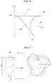
- the isentropic block efficiency compared to the prior art is for the second embodiment to 3/4 teeth number ratio in FIG. 5 illustrated. There are two curves with the same pressure ratio.
- the concrete reproduced pressure ratio is 2.0 (ratio of outlet pressure to inlet pressure).
- the isentropic block efficiency was significantly improved over the values achievable with the prior art.
- FIG. 6 Fig. 13 illustrates the isentropic block efficiency as compared with the prior art in the fourth embodiment (5/6 teeth number ratio). Again, two curves of equal pressure ratio are shown. The pressure ratio shown here is 9.0 (ratio of outlet pressure to inlet pressure).
- the isentropic blocking efficiency could be significantly improved compared to the values obtainable with the prior art.
- each specified delivery quantity corresponds to the delivery volume flow of the compressor block based on the intake state.
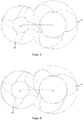
- FIG. 7b shows in a cross-sectional view, the tooth space surfaces A6 and A7 and a side view of a blow hole.
- FIG. 7b to illustrate the tooth gap surfaces A6 and A7 profiles shown correspond to that for a teeth ratio of 3/4 based on FIG. 1 illustrated embodiment.
- FIG. 7b the location of the coordinate system of Fig. 7k illustrated Blasloch Treatment A Bl in relation to the rotor pair.
- the coordinate system is spanned by the u-axis parallel to the rotor end faces along the pressure-side intersection edge 11.
- the pressure-side blowing hole lies in the described coordinate system and quite concretely in a plane perpendicular to the rotor end faces between the pressure-side intersection edge 11 and an engagement line point K2 of the pressure-side part of the engagement line.
- the engagement line 10 is divided into two sections by the connecting line between the two center points C1 and C2: the suction-side part of the engagement line is shown below, the pressure-side part above the connection line.
- K2 denotes the point of the pressure-side part of the engagement line 10 which is furthest from the straight line through C1 and C2.
- the intersection of the head circles of the two rotors creates a pressure-side intersection edge 11 and a suction-side intersection edge 12
- Fig. 7b is the pressure-side intersection edge 11 in one Foresight view shown as a point. The same applies to the representation of the suction-side intersection edge 12th
- the u-axis is a parallel to the rotor end faces and corresponds in an end-sectional view to the vector from the engagement line point K2 to the pressure-side intersection edge 11. Further details on the pressure-side blow hole area A Bl emerge FIG. 7k ,
- FIG. 7c shows in a cross-sectional view, a tooth of the sub-rotor with the running inside the rotor tooth concentric arcs B 25 , B 50 , B 75 around the center C1 with the associated radii r 25 , r 50 , r 75 and the associated arc lengths b 25 , b 50 b 75 .
- the circular arcs B 25 , B 50 , B 75 are each bounded by the leading tooth flank F V and the trailing tooth flank F N.
- the basis of FIG. 7c shown profile profile of the leading tooth flank F V and the trailing tooth flank F N corresponds to the basis of the FIG. 4 for a teeth ratio of 5/6 explained embodiment.
- FIG. 7d shows in an end-sectional view between the considered tooth of the sub rotor and the adjacent tooth of the sub rotor foot points F1 and F2 at the root circle and at the radially outermost point of the tooth apex F5. Furthermore, the defined by the points F1, F2 and F5 triangle D Z is shown.
- tooth pitch angle ⁇ corresponding to 360 ° / number of teeth of the sub rotor.
- profile profile of the leading tooth flank F V and the trailing tooth flank F N corresponds to the basis of the FIG. 4 for a teeth ratio of 5/6 explained embodiment.
- Figure 7e shows in a cross-sectional view, the cross-sectional area A0 of a tooth of the sub-rotor, which is bounded by the running between F1 and F2 circular arc B around the center C1.
- the basis of Figure 7e shown profile profile of the leading tooth flank F V and the trailing tooth flank F N corresponds to the basis of the FIG. 4 for a teeth ratio of 5/6 explained embodiment.
- Figure 7f shows in an end-sectional view the offset angle ⁇ . This is defined by the offset from point F11 to point F12 considered in the direction of rotation of the secondary rotor.
- F11 is a point on the half circular arc B between F1 and F2 around the center point C1 and accordingly corresponds to the intersection of the bisector of the tooth pitch angle ⁇ with the arc B.
- F12 results from the point of intersection of the radial ray R drawn from the center C1 to the vertex F5 with the arc B.
- profile profile profile of the leading tooth flank F V and the trailing tooth flank F N corresponds to the basis of the FIG. 4 for a teeth ratio of 5/6 explained embodiment.
- FIG. 7g shows in an end-sectional view the turning point F8 on the trailing tooth flank F N of the secondary rotor, in which the curvature of the course of the tooth profile between the head and root circle changes.
- the trailing tooth flank F N of the sub rotor is subdivided by the point F8 into a substantially convexly curved portion between F8 and the vertex F5 and a substantially concavely curved portion between F8 and the root F1.
- FIG. 7h shows in a cross-sectional view two intersections of the radial beam R 10 from C1 to F10 with the leading tooth flank F V of the sub rotor, the point F10 that point of the leading tooth flank F V , which lies on the head circle KK 1 with rk 1 and furthest from F5 is spaced.
- the tooth flank follows radially outside so over a defined section of a circular arc ARC 1 with radius rk 1 to the defined by the axis C1 center of the secondary rotor.
- profile curves of the leading tooth flank F V and the trailing tooth flank F N correspond to the embodiment described for a tooth ratio of 3/4 FIG. 1 ,
- FIG. 7i shows in a cross-sectional view the tooth profile divided by the radial beam R drawn from C1 to F5.
- the tooth profile is divided into an area portion A4 associated with the trailing tooth flank FN and an area portion A5 associated with the leading tooth flank F V.
- the basis of FIG. 7i explained profile curves of the leading tooth flank F V and the trailing tooth flank F N correspond to the embodiment described for a teeth ratio of 5/6 FIG. 4 ,
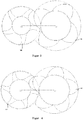
- FIG. 7j shows in an end-sectional view, the engagement line 10 between the main and secondary rotor and the two concentric circles around the point C with the radii r 1 and r 2 to describe the characteristic features of the course of the suction-side part of the engagement line.
- the engagement line 10 is divided into two sections by the connection path between the first axis C1 and the second axis C2: the suction-side part of the engagement line is below, the pressure-side part above the connection path C 1 C 2 shown.
- Point C is the point of contact of the pitch circle WK 1 of the secondary rotor with the pitch circle WK 2 of the main rotor.
- K4 denotes the point of the suction-side part of the engagement line which is farthest from the connection path between C1 and C2.
- Radius r 1 is the distance between K5 and C
- radius r 2 is the distance between K4 and C.
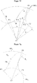
- FIG. 7k is a diagrammatic representation of FIG. 7k.
- FIG. 7k shows a pressure-side Blasloch Treatment A Bl of a working chamber in a sectional view perpendicular to the rotor end faces.
- the limitation of the Blasloch composition A Bl arises here from the cut line 27 of the imaginary planar surface as described above with the leading female rotor flank F v, the cut line 26 of the plane with the trailing HR-edge and a line segment [K1 K3] of the pressure side intersection edge. 11
- FIG. 8 is the repeatedly addressed wrap ⁇ again illustrated. Specifically, it is the angle ⁇ , around which the endcut is twisted from the suction side to the pressure side rotor end face. This is illustrated by the rotation of the profile between a pressure-side end face 13 and a suction-side end face 14 by the angle ⁇ HR in the main rotor HR.
- FIG. 9 shows a schematic sectional view of a compressor block 19 comprising a housing 15 and stored therein two mutually paired rotors, namely a main rotor HR and a secondary rotor NR.
- Main rotor HR and secondary rotor NR are each rotatably supported in the housing 15 via suitable bearings 16.
- a drive power can be applied to a shaft 17 of the main rotor HR, for example with a motor (not shown) via a coupling 18.
- the compressor block shown is an oil-injected screw compressor in which the torque transmission between the main rotor HR and the secondary rotor NR takes place directly over the rotor flanks. In contrast to can be avoided in a dry screw compressor touching the rotor edges by means of a synchronization gear (not shown).
- FIG. 10 are still a toothed main rotor HR and side rotor NR shown in a perspective view.
- FIG. 11 shows the spatial engagement line 10 exactly one tooth gap 23.
- the profile gap length l sp is the length of the spatial engagement line exactly one tooth gap 23. This corresponds to the profile gap length exactly one tooth pitch.
- the total torque from the gas forces on the secondary rotor is composed of the sum of the torque effects of the gas pressures in all working chambers on the sub-surfaces of the sub-rotor which delimit the respective working chambers.
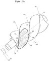
- Fig. 12a is such, a working chamber limiting partial surface (22) of the secondary rotor shown by hatching example.
- FIG. 12b shows the breakdown of in FIG. 12a illustrated a working chamber limiting part surface (22) in a dotted surface (28) and a cross-hatched surface (29). Only the cross-hatched area (29) contributes to the torque.
- the sub-surface (22) results from the actual Stirnroughmony and the slope of the secondary rotor.
- the slope of the secondary rotor refers to the pitch of the helical toothing of the secondary rotor.
- the partial surface limiting three-dimensional engagement line (10) is also determined by the front section design of the secondary rotor and the slope.
- Partial surface (22) is also limited by section line (27). Details of cutting line (27) were already in the context of FIGS. 7b and 7k shown and described. The same applies to the engagement point K2.
- the dependent on the angular position of the secondary rotor to the main rotor concrete length of a working chamber in the direction of the rotor axis between the Maurotorstirn preparation (20) on the one hand and the boundary by the three-dimensional line of action (10) and cutting line (27) on the other hand does not play an essential role, because - as in the relevant literature is described - the gas pressures on areas of the rotor surface, which correspond to complete tooth gaps in a sectional plane perpendicular to the axis of the rotor (in Fig. 12b shown dotted), make no contribution to the torque.
- the slope of the secondary rotor affects only the amount, but not on the effective direction of the torque.
- profile profiles in the exemplary embodiments discussed above will be described below purely by way of example FIGS. 1 to 4 explained in more detail.
- profile profiles can also be generated by means of publicly available computer programs, as is well known to the person skilled in the art.
- SV_Win a project of the Vienna University of Technology
- An alternative, publicly available computer program also includes the DISCO software and, in particular, the SCORPATH module of the City University of London (Center for Positive Displacement Compressor Technology).
- DISCO software For general information, see http://www.city-compressors.co. uk /. Information about installing the software can be found at http://www.staff.city.ac.uk/ ⁇ ra600/DISCO/DISCO/Instalation%20instructions.pdf.
- a preview of the DISCO software can be found at http://www.staff.city.ac.uk/ ⁇ ra600/DISCO/DISCO%20Preview.htm.
- ScrewView Another alternative software is the software ScrewView, which is also available in the Dissertation “Directed Evolutionary Algorithms” by Stefan Berlik, Dortmund 2006 (p. 173 f .) mentioned.
- the ScrewView software is described in more detail on the website http://pi.informatik.unirisonen.de/Mitarbeiter/berlik/excellente/ in connection with the project "Method for designing dry-running rotary displacement machines”.
- a tooth with trailing rotor edge F N and leading rotor edge F V is generated as follows:
- the section S1 to S2 results from a circular arc on the secondary rotor NR about the center point C1, generated by the circular arc section T1 to T2 about the center point C2 on the Main rotor HR.
- the section S2 to S3 results from an envelope to a trochoid generated by arc section T2 to T3 about the center M4 on the main rotor HR.
- the section S3 to S4 is surrounded by a circular arc defines the midpoint M1.
- the section S4 to S5 is given by a circular arc around the center M2.
- the section S5 to S6 is defined by a circular arc about the center C1.
- the subsequent section S6 to S7 is given by a circular arc around the center M3.
- the section S7 to S1 is defined by an envelope to a trochoid generated by the circular arc section T7 to T1 around the center M5 on the main rotor HR.
- the profile profile of the teeth of the main rotor HR is for the embodiment of the FIGS. 1 to 4 also on the basis of FIGS. 13 to 16 briefly explained below.
- the section T1-T2 results from a circular arc on the main rotor HR about the center C2 on the main rotor HR.
- the section T2-T3 is defined by the arc on the main rotor HR around the center M4.
- the section T3-T4 results from an envelope to a trochoid generated by the section S3-S4 on the sub rotor NR.
- the section T4-T5 is given by an envelope to a trochoid generated by the section S4-S5 on the sub rotor.
- the section T5-T6 is defined by a circular arc around the center point C2 generated by the circular arc section S5-S6 about the center point C1 on the sub rotor NR.
- the section T6-T7 results from an envelope to a trochoid generated from the section S6-S7 on the sub rotor NR.
- the section T7-T1 is defined by a circular arc around the center point M5.
Landscapes
- Engineering & Computer Science (AREA)
- Mechanical Engineering (AREA)
- General Engineering & Computer Science (AREA)
- Applications Or Details Of Rotary Compressors (AREA)
- Rotary Pumps (AREA)
- Structures Of Non-Positive Displacement Pumps (AREA)
Priority Applications (2)
| Application Number | Priority Date | Filing Date | Title |
|---|---|---|---|
| EP23198449.3A EP4273403A3 (fr) | 2014-04-25 | 2015-04-27 | Paire de rotors pour bloc de compresseur d'une visseuse |
| EP19190907.6A EP3597920B1 (fr) | 2014-04-25 | 2015-04-27 | Paire de rotors pour bloc de compresseur d'une visseuse |
Applications Claiming Priority (3)
| Application Number | Priority Date | Filing Date | Title |
|---|---|---|---|
| DE102014105882.8A DE102014105882A1 (de) | 2014-04-25 | 2014-04-25 | Rotorpaar für einen Verdichterblock einer Schraubenmaschine |
| PCT/EP2015/059070 WO2015162296A2 (fr) | 2014-04-25 | 2015-04-27 | Paire de rotors pour bloc de compresseur d'une visseuse |
| EP15736405.0A EP3134649B2 (fr) | 2014-04-25 | 2015-04-27 | Paire de rotors pour bloc de compresseur d'une visseuse |
Related Parent Applications (2)
| Application Number | Title | Priority Date | Filing Date |
|---|---|---|---|
| EP15736405.0A Division EP3134649B2 (fr) | 2014-04-25 | 2015-04-27 | Paire de rotors pour bloc de compresseur d'une visseuse |
| EP15736405.0A Division-Into EP3134649B2 (fr) | 2014-04-25 | 2015-04-27 | Paire de rotors pour bloc de compresseur d'une visseuse |
Related Child Applications (4)
| Application Number | Title | Priority Date | Filing Date |
|---|---|---|---|
| EP23198449.3A Division-Into EP4273403A3 (fr) | 2014-04-25 | 2015-04-27 | Paire de rotors pour bloc de compresseur d'une visseuse |
| EP23198449.3A Division EP4273403A3 (fr) | 2014-04-25 | 2015-04-27 | Paire de rotors pour bloc de compresseur d'une visseuse |
| EP19190907.6A Division-Into EP3597920B1 (fr) | 2014-04-25 | 2015-04-27 | Paire de rotors pour bloc de compresseur d'une visseuse |
| EP19190907.6A Division EP3597920B1 (fr) | 2014-04-25 | 2015-04-27 | Paire de rotors pour bloc de compresseur d'une visseuse |
Publications (3)
| Publication Number | Publication Date |
|---|---|
| EP3358189A1 true EP3358189A1 (fr) | 2018-08-08 |
| EP3358189B1 EP3358189B1 (fr) | 2023-10-11 |
| EP3358189B9 EP3358189B9 (fr) | 2024-01-03 |
Family
ID=53541638
Family Applications (4)
| Application Number | Title | Priority Date | Filing Date |
|---|---|---|---|
| EP18163593.9A Revoked EP3358189B9 (fr) | 2014-04-25 | 2015-04-27 | Paire de rotors pour bloc de compresseur d'une visseuse |
| EP19190907.6A Active EP3597920B1 (fr) | 2014-04-25 | 2015-04-27 | Paire de rotors pour bloc de compresseur d'une visseuse |
| EP15736405.0A Active EP3134649B2 (fr) | 2014-04-25 | 2015-04-27 | Paire de rotors pour bloc de compresseur d'une visseuse |
| EP23198449.3A Pending EP4273403A3 (fr) | 2014-04-25 | 2015-04-27 | Paire de rotors pour bloc de compresseur d'une visseuse |
Family Applications After (3)
| Application Number | Title | Priority Date | Filing Date |
|---|---|---|---|
| EP19190907.6A Active EP3597920B1 (fr) | 2014-04-25 | 2015-04-27 | Paire de rotors pour bloc de compresseur d'une visseuse |
| EP15736405.0A Active EP3134649B2 (fr) | 2014-04-25 | 2015-04-27 | Paire de rotors pour bloc de compresseur d'une visseuse |
| EP23198449.3A Pending EP4273403A3 (fr) | 2014-04-25 | 2015-04-27 | Paire de rotors pour bloc de compresseur d'une visseuse |
Country Status (7)
| Country | Link |
|---|---|
| US (4) | US10400769B2 (fr) |
| EP (4) | EP3358189B9 (fr) |
| JP (1) | JP6545787B2 (fr) |
| CN (1) | CN106536933B (fr) |
| DE (2) | DE102014105882A1 (fr) |
| ES (3) | ES2967470T3 (fr) |
| WO (1) | WO2015162296A2 (fr) |
Families Citing this family (8)
| Publication number | Priority date | Publication date | Assignee | Title |
|---|---|---|---|---|
| DE102014105882A1 (de) * | 2014-04-25 | 2015-11-12 | Kaeser Kompressoren Se | Rotorpaar für einen Verdichterblock einer Schraubenmaschine |
| DE102016011436A1 (de) * | 2016-09-21 | 2018-03-22 | Knorr-Bremse Systeme für Nutzfahrzeuge GmbH | Anordnung von Schrauben für einen Schraubenkompressor für ein Nutzfahrzeug |
| WO2018193112A1 (fr) * | 2017-04-20 | 2018-10-25 | Cogenergy Suisse Sa | Réducteur de pression pour moteur à combustion interne rotatif |
| JP6899288B2 (ja) * | 2017-09-04 | 2021-07-07 | 株式会社日立産機システム | スクリュー圧縮機 |
| DE102020103384B4 (de) | 2020-02-11 | 2025-11-13 | Gardner Denver Deutschland Gmbh | Schraubenverdichter mit einseitig gelagerten Rotoren |
| JP7616859B2 (ja) * | 2020-10-23 | 2025-01-17 | 株式会社日立産機システム | スクリュー圧縮機及びスクリューロータ |
| IT202100004139A1 (it) * | 2021-02-23 | 2022-08-23 | Settima Mecc S R L | Assieme di viti per pompa a tre viti e pompa a viti comprendente detto assieme |
| IT202100004148A1 (it) * | 2021-02-23 | 2022-08-23 | Settima Mecc S R L | Assieme di viti per pompa a tre viti e pompa a tre viti comprendente detto assieme |
Citations (4)
| Publication number | Priority date | Publication date | Assignee | Title |
|---|---|---|---|---|
| US2622787A (en) * | 1947-07-16 | 1952-12-23 | Jarvis C Marble | Helical rotary engine |
| DE1428265A1 (de) * | 1964-05-22 | 1969-01-16 | Svenska Rotor Maskiner Ab | Schraubenrotormaschine |
| WO1997021926A1 (fr) * | 1995-12-11 | 1997-06-19 | Ateliers Busch S.A. | Vis transporteuses jumelees |
| EP3134649A2 (fr) | 2014-04-25 | 2017-03-01 | Kaeser Kompressoren SE | Paire de rotors pour bloc de compresseur d'une visseuse |
Family Cites Families (27)
| Publication number | Priority date | Publication date | Assignee | Title |
|---|---|---|---|---|
| FR953057A (fr) | 1946-07-18 | 1949-11-30 | Ljungstroms Angturbin Ab | Perfectionnements aux compresseurs et aux moteurs à roue hélicoïdale |
| GB627162A (en) | 1946-07-18 | 1949-07-29 | Ljungstroms Angturbin Ab | Improvements in rotary devices of the helical screw wheel type |
| US3138110A (en) | 1962-06-05 | 1964-06-23 | Joseph E Whitfield | Helically threaded intermeshing rotors |
| US3282495A (en) | 1964-04-29 | 1966-11-01 | Dresser Ind | Sealing arrangement for screw-type compressors and similar devices |
| US3275226A (en) | 1965-02-23 | 1966-09-27 | Joseph E Whitfield | Thrust balancing and entrapment control means for screw type compressors and similardevices |
| US3437263A (en) * | 1966-06-22 | 1969-04-08 | Atlas Copco Ab | Screw rotor machines |
| DE2911415C2 (de) | 1979-03-23 | 1982-04-15 | Karl Prof.Dr.-Ing. 3000 Hannover Bammert | Parallel- und außenachsige Rotationskolbenmaschine mit Kämmeingriff |
| US4412796A (en) | 1981-08-25 | 1983-11-01 | Ingersoll-Rand Company | Helical screw rotor profiles |
| SE429783B (sv) | 1981-12-22 | 1983-09-26 | Sullair Tech Ab | Rotorer for en skruvrotormaskin |
| US4583927A (en) * | 1983-03-16 | 1986-04-22 | Kabushiki Kaisha Kobe Seiko Sho | Screw rotor mechanism |
| JPH079239B2 (ja) * | 1984-04-11 | 1995-02-01 | 株式会社日立製作所 | スクリュー真空ポンプ |
| GB8413619D0 (en) | 1984-05-29 | 1984-07-04 | Compair Ind Ltd | Screw rotor machines |
| US4527967A (en) * | 1984-08-31 | 1985-07-09 | Dunham-Bush, Inc. | Screw rotor machine with specific tooth profile |
| US4643654A (en) * | 1985-09-12 | 1987-02-17 | American Standard Inc. | Screw rotor profile and method for generating |
| US5018953A (en) * | 1989-05-18 | 1991-05-28 | Ishikawajima-Harima Jukogyo Kabushiki Kaisha | Rotor with eccentrically positioned retainer pin |
| US5624250A (en) * | 1995-09-20 | 1997-04-29 | Kumwon Co., Ltd. | Tooth profile for compressor screw rotors |
| KR100313638B1 (ko) | 1998-05-06 | 2001-12-12 | 최성규 | 자동차용스크류형수퍼차져로타의치형 |
| KR100425414B1 (ko) * | 2002-01-25 | 2004-04-08 | 이 재 영 | 스크류 압축기용 로우터의 치형 |
| US7163387B2 (en) * | 2002-12-16 | 2007-01-16 | Carrier Corporation | Meshing helical rotors |
| GB2401302A (en) | 2003-05-06 | 2004-11-10 | Dewhirst Group Ltd | Tailored apparel with moisture management |
| JP2007146659A (ja) * | 2005-11-24 | 2007-06-14 | Hitachi Industrial Equipment Systems Co Ltd | 油冷式圧縮機 |
| JP4951571B2 (ja) * | 2008-03-31 | 2012-06-13 | 株式会社日立産機システム | スクリュー圧縮機 |
| IT1394590B1 (it) * | 2009-05-21 | 2012-07-05 | Robuschi S P A | Compressore a vite |
| CN102052322B (zh) | 2010-12-23 | 2012-10-31 | 上海耐浦流体机械科技有限公司 | 一种双螺杆压缩机转子型线 |
| CN102352840B (zh) | 2011-09-29 | 2013-08-28 | 陕西丰赜机电科技有限公司 | 螺杆转子端面廓形副及其构造方法 |
| GB2501302B (en) * | 2012-04-19 | 2016-08-31 | The City Univ | Reduced noise screw machines |
| CN103195716B (zh) | 2013-05-07 | 2015-09-02 | 巫修海 | 一种新型齿形螺杆型线 |
-
2014
- 2014-04-25 DE DE102014105882.8A patent/DE102014105882A1/de active Pending
-
2015
- 2015-04-27 WO PCT/EP2015/059070 patent/WO2015162296A2/fr not_active Ceased
- 2015-04-27 DE DE202015009525.9U patent/DE202015009525U1/de not_active Expired - Lifetime
- 2015-04-27 EP EP18163593.9A patent/EP3358189B9/fr not_active Revoked
- 2015-04-27 EP EP19190907.6A patent/EP3597920B1/fr active Active
- 2015-04-27 EP EP15736405.0A patent/EP3134649B2/fr active Active
- 2015-04-27 US US15/306,592 patent/US10400769B2/en active Active
- 2015-04-27 CN CN201580022693.7A patent/CN106536933B/zh active Active
- 2015-04-27 ES ES18163593T patent/ES2967470T3/es active Active
- 2015-04-27 EP EP23198449.3A patent/EP4273403A3/fr active Pending
- 2015-04-27 JP JP2017507082A patent/JP6545787B2/ja active Active
- 2015-04-27 ES ES15736405T patent/ES2668317T5/es active Active
- 2015-04-27 ES ES19190907T patent/ES2963314T3/es active Active
-
2019
- 2019-08-02 US US16/530,002 patent/US11248606B2/en active Active
-
2022
- 2022-01-17 US US17/577,212 patent/US20220136504A1/en not_active Abandoned
-
2023
- 2023-11-03 US US18/501,260 patent/US12352266B2/en active Active
Patent Citations (4)
| Publication number | Priority date | Publication date | Assignee | Title |
|---|---|---|---|---|
| US2622787A (en) * | 1947-07-16 | 1952-12-23 | Jarvis C Marble | Helical rotary engine |
| DE1428265A1 (de) * | 1964-05-22 | 1969-01-16 | Svenska Rotor Maskiner Ab | Schraubenrotormaschine |
| WO1997021926A1 (fr) * | 1995-12-11 | 1997-06-19 | Ateliers Busch S.A. | Vis transporteuses jumelees |
| EP3134649A2 (fr) | 2014-04-25 | 2017-03-01 | Kaeser Kompressoren SE | Paire de rotors pour bloc de compresseur d'une visseuse |
Non-Patent Citations (13)
| Title |
|---|
| A KOVACEVIC ET AL: "Grid Generation for Screw Compressors with Variable Geometry Rotors", APCOM & ISCM, December 2013 (2013-12-01), pages 1 - 10, XP055623048 |
| D. ZAYTSEV, C.A. INFANTE FERREIRA: "Profile generation method for twin screw compressor rotors based on the meshing line", INTERNATIONAL JOURNAL OF REFRIGERATION, vol. 28, 2005, pages 744 - 755, XP055545784 |
| J.S. FLEMING, Y. TANGH ANDERSON: "Optimisation Techniques Applied to the Design of a Refrigeration TiN Screw Compressor", INTERNATIONAL COMPRESSOR ENGINEERINGCONFERENCE, 1994, pages 641 - 645, XP055545797 |
| KOVASEVIC A. ET AL: "CF Grid generation and analysis of screw compressor with variable geometry rotors", APCOM & ISCM, 1 January 2013 (2013-01-01), pages 601 - 612, XP055545705 |
| NIKOLA STOSIC ET AL: "Review of Mathematical Models in Performance Calculation of Screw Compressors", INTERNATIONAL JOURNAL OF FLUID MACHINERY ANDSYSTEMS, vol. 4, no. 2, 2011, pages 200 - 217, XP055545676 |
| P.J SINGH, J.L. BOWMAN: "Effect of Design Parameters on Oil-Flooded Screw Compressor Performance", INTERNATIONAL COMPRESSOR ENGINEERINGCONFERENCE OF 1986 (AUGUST 4-7), August 1986 (1986-08-01), pages 71, XP055545603 |
| PROFESSOR NIKOLA STOSIC ET AL: "Screw Compressors - Mathematical Modelling and Performance Calculation", 2005, SPRINGER, article "Introduction", pages: 13-39, 64-71,77-87,93 - 96, XP055623074 |
| TANG Y. ET AL: "Obtaining the Optimum Geometrical Parameters of a Refrigeration Helical Screw Compressor", INTERNATIONAL COMPRESSOR ENGINEERINGCONFERENCE 1992 (PAPER 811), 1992, pages 221 - 227, XP055545652 |
| W.S. LEER, R. H. MA, W.F. WU, S.L. CHEN, H.W. HSIA: "Performance and Bearing Load Analysis of a Twin Screw Air Compressor", CHINESE JOURNAL OF MECHANICS, vol. 15, no. 2, 1999, pages 69 - 78, XP055545714, doi:10.1017/S1727719100000344 |
| YOU C. X. ET AL: "Optimum Rotor Geometrical Parameters in Refrigeration Helical Twin Screw Compressors", INTERNATIONAL COMPRESSOR ENGINEERING CONFERENCE 1996 (PAPER 1074), 1996, pages 1 - 6, XP055545687 |
| YU-REN WU ET AL: "Improved rotor profiling based on the arbitrary sealing line for twin-screw compressors", MECHANISM AND MACHINE THEORY, vol. 43, 2008, pages 695 - 711, XP055545752 |
| YU-REN WU ET AL: "Rotor Profile Design for the Twin-Screw Compressor Based on the Normal-Rack Generation Method", THE JOURNAL OF MECHANICAL DESIGN, vol. 130, April 2008 (2008-04-01), pages 1 - 8, XP055545643 |
| YU-REN WUZHANG-HUA FONG: "Optimisation design of an explicitly defined rack for the generation of rotors for twin-screw compressors", MECHANISM AND MACHINE THEORY, vol. 44, 2009, pages 66 - 82, XP055545726 |
Also Published As
| Publication number | Publication date |
|---|---|
| EP3134649A2 (fr) | 2017-03-01 |
| EP3358189B1 (fr) | 2023-10-11 |
| EP3134649B1 (fr) | 2018-04-04 |
| ES2967470T3 (es) | 2024-04-30 |
| EP3597920B1 (fr) | 2023-09-06 |
| US10400769B2 (en) | 2019-09-03 |
| EP3134649B2 (fr) | 2022-12-14 |
| DE102014105882A1 (de) | 2015-11-12 |
| US20170045050A1 (en) | 2017-02-16 |
| JP2017514069A (ja) | 2017-06-01 |
| EP3358189B9 (fr) | 2024-01-03 |
| EP3597920A3 (fr) | 2021-03-24 |
| JP6545787B2 (ja) | 2019-07-17 |
| US12352266B2 (en) | 2025-07-08 |
| EP4273403A3 (fr) | 2024-04-03 |
| US20180112663A2 (en) | 2018-04-26 |
| US20200040894A1 (en) | 2020-02-06 |
| US11248606B2 (en) | 2022-02-15 |
| DE202015009525U1 (de) | 2018-02-15 |
| US20240175436A1 (en) | 2024-05-30 |
| EP3597920A2 (fr) | 2020-01-22 |
| US20220136504A1 (en) | 2022-05-05 |
| EP4273403A2 (fr) | 2023-11-08 |
| WO2015162296A2 (fr) | 2015-10-29 |
| ES2668317T5 (es) | 2023-04-10 |
| ES2668317T3 (es) | 2018-05-17 |
| EP3134649B9 (fr) | 2019-02-27 |
| CN106536933B (zh) | 2019-07-12 |
| WO2015162296A3 (fr) | 2015-12-23 |
| CN106536933A (zh) | 2017-03-22 |
| ES2963314T3 (es) | 2024-03-26 |
Similar Documents
| Publication | Publication Date | Title |
|---|---|---|
| EP3134649B1 (fr) | Paire de rotors pour bloc de compresseur d'une visseuse | |
| EP1303702B1 (fr) | Rotors a vis jumelles et machines volumetriques les contenant | |
| EP2847467B1 (fr) | Compresseur à vis | |
| DE4330609A1 (de) | Rotationskolbenmaschine in Spiralbauweise | |
| EP1340912A1 (fr) | Machine à engrenage interne avec jeu de dentures | |
| DE102013009040B4 (de) | Spindelkompressor mit hoher innerer Verdichtung | |
| EP3507496B1 (fr) | Pompe à vide à compression sèche | |
| CH657897A5 (de) | Schraubenrotormaschine fuer ein arbeitsfluid. | |
| EP1957798A1 (fr) | Compresseur à vis | |
| DE10208408A1 (de) | Zahnradverzahnung | |
| CH699438B1 (de) | Schraubenverdichter für grosse Antriebsleistungen. | |
| DE2508435A1 (de) | Rotorpaar zur drehung im kaemmeingriff in einer parallel- und aussenachsigen rotationskolbenmaschine | |
| DE102017106781A1 (de) | Rotorflankenpaarungen | |
| EP3507497A1 (fr) | Rotor à vis de pompe à vide | |
| EP3507495B1 (fr) | Pompe à vide à vis | |
| DE1428270B2 (de) | Schraubenverdichter mit im Kämmeingriff rotierenden Schraubenrotoren | |
| DE69326606T2 (de) | Schraubenkolbenmaschine | |
| DE102013110091B3 (de) | Wälzkolbenpumpe mit zwei Rotoren | |
| EP1362188B1 (fr) | Machine a piston rotatif pour fluides compressibles | |
| DE4403649A1 (de) | Lagerung und Antrieb der Rotoren eines Schraubenrotorverdichters | |
| EP3737863A1 (fr) | Compresseur | |
| DE102018103723B4 (de) | Verzahnung für eine Gerotorpumpe und Verfahren zur geometrischen Bestimmung derselben | |
| DE2460752A1 (de) | Drehkolbenmaschine | |
| EP2613052B1 (fr) | Compresseur à pistons rotatifs ou pompe à pistons rotatifs | |
| DE60223388T2 (de) | Verdrängerpumpe mit gegendruckverhinderung |
Legal Events
| Date | Code | Title | Description |
|---|---|---|---|
| PUAI | Public reference made under article 153(3) epc to a published international application that has entered the european phase |
Free format text: ORIGINAL CODE: 0009012 |
|
| STAA | Information on the status of an ep patent application or granted ep patent |
Free format text: STATUS: THE APPLICATION HAS BEEN PUBLISHED |
|
| STAA | Information on the status of an ep patent application or granted ep patent |
Free format text: STATUS: REQUEST FOR EXAMINATION WAS MADE |
|
| AC | Divisional application: reference to earlier application |
Ref document number: 3134649 Country of ref document: EP Kind code of ref document: P |
|
| AK | Designated contracting states |
Kind code of ref document: A1 Designated state(s): AL AT BE BG CH CY CZ DE DK EE ES FI FR GB GR HR HU IE IS IT LI LT LU LV MC MK MT NL NO PL PT RO RS SE SI SK SM TR |
|
| 17P | Request for examination filed |
Effective date: 20180718 |
|
| RBV | Designated contracting states (corrected) |
Designated state(s): AL AT BE BG CH CY CZ DE DK EE ES FI FR GB GR HR HU IE IS IT LI LT LU LV MC MK MT NL NO PL PT RO RS SE SI SK SM TR |
|
| TPAC | Observations filed by third parties |
Free format text: ORIGINAL CODE: EPIDOSNTIPA |
|
| STAA | Information on the status of an ep patent application or granted ep patent |
Free format text: STATUS: EXAMINATION IS IN PROGRESS |
|
| 17Q | First examination report despatched |
Effective date: 20190109 |
|
| TPAC | Observations filed by third parties |
Free format text: ORIGINAL CODE: EPIDOSNTIPA |
|
| TPAC | Observations filed by third parties |
Free format text: ORIGINAL CODE: EPIDOSNTIPA |
|
| TPAC | Observations filed by third parties |
Free format text: ORIGINAL CODE: EPIDOSNTIPA |
|
| GRAP | Despatch of communication of intention to grant a patent |
Free format text: ORIGINAL CODE: EPIDOSNIGR1 |
|
| STAA | Information on the status of an ep patent application or granted ep patent |
Free format text: STATUS: GRANT OF PATENT IS INTENDED |
|
| INTG | Intention to grant announced |
Effective date: 20230421 |
|
| P01 | Opt-out of the competence of the unified patent court (upc) registered |
Effective date: 20230531 |
|
| GRAS | Grant fee paid |
Free format text: ORIGINAL CODE: EPIDOSNIGR3 |
|
| GRAA | (expected) grant |
Free format text: ORIGINAL CODE: 0009210 |
|
| STAA | Information on the status of an ep patent application or granted ep patent |
Free format text: STATUS: THE PATENT HAS BEEN GRANTED |
|
| AC | Divisional application: reference to earlier application |
Ref document number: 3134649 Country of ref document: EP Kind code of ref document: P |
|
| AK | Designated contracting states |
Kind code of ref document: B1 Designated state(s): AL AT BE BG CH CY CZ DE DK EE ES FI FR GB GR HR HU IE IS IT LI LT LU LV MC MK MT NL NO PL PT RO RS SE SI SK SM TR |
|
| REG | Reference to a national code |
Ref country code: GB Ref legal event code: FG4D Free format text: NOT ENGLISH |
|
| REG | Reference to a national code |
Ref country code: CH Ref legal event code: EP |
|
| REG | Reference to a national code |
Ref country code: DE Ref legal event code: R096 Ref document number: 502015016637 Country of ref document: DE |
|
| REG | Reference to a national code |
Ref country code: IE Ref legal event code: FG4D Free format text: LANGUAGE OF EP DOCUMENT: GERMAN |
|
| REG | Reference to a national code |
Ref country code: CH Ref legal event code: PK Free format text: BERICHTIGUNG B9 |
|
| REG | Reference to a national code |
Ref country code: LT Ref legal event code: MG9D |
|
| REG | Reference to a national code |
Ref country code: NL Ref legal event code: MP Effective date: 20231011 |
|
| PG25 | Lapsed in a contracting state [announced via postgrant information from national office to epo] |
Ref country code: NL Free format text: LAPSE BECAUSE OF FAILURE TO SUBMIT A TRANSLATION OF THE DESCRIPTION OR TO PAY THE FEE WITHIN THE PRESCRIBED TIME-LIMIT Effective date: 20231011 |
|
| PG25 | Lapsed in a contracting state [announced via postgrant information from national office to epo] |
Ref country code: GR Free format text: LAPSE BECAUSE OF FAILURE TO SUBMIT A TRANSLATION OF THE DESCRIPTION OR TO PAY THE FEE WITHIN THE PRESCRIBED TIME-LIMIT Effective date: 20240112 |
|
| PG25 | Lapsed in a contracting state [announced via postgrant information from national office to epo] |
Ref country code: IS Free format text: LAPSE BECAUSE OF FAILURE TO SUBMIT A TRANSLATION OF THE DESCRIPTION OR TO PAY THE FEE WITHIN THE PRESCRIBED TIME-LIMIT Effective date: 20240211 |
|
| PG25 | Lapsed in a contracting state [announced via postgrant information from national office to epo] |
Ref country code: LT Free format text: LAPSE BECAUSE OF FAILURE TO SUBMIT A TRANSLATION OF THE DESCRIPTION OR TO PAY THE FEE WITHIN THE PRESCRIBED TIME-LIMIT Effective date: 20231011 |
|
| PG25 | Lapsed in a contracting state [announced via postgrant information from national office to epo] |
Ref country code: LT Free format text: LAPSE BECAUSE OF FAILURE TO SUBMIT A TRANSLATION OF THE DESCRIPTION OR TO PAY THE FEE WITHIN THE PRESCRIBED TIME-LIMIT Effective date: 20231011 Ref country code: IS Free format text: LAPSE BECAUSE OF FAILURE TO SUBMIT A TRANSLATION OF THE DESCRIPTION OR TO PAY THE FEE WITHIN THE PRESCRIBED TIME-LIMIT Effective date: 20240211 Ref country code: GR Free format text: LAPSE BECAUSE OF FAILURE TO SUBMIT A TRANSLATION OF THE DESCRIPTION OR TO PAY THE FEE WITHIN THE PRESCRIBED TIME-LIMIT Effective date: 20240112 Ref country code: BG Free format text: LAPSE BECAUSE OF FAILURE TO SUBMIT A TRANSLATION OF THE DESCRIPTION OR TO PAY THE FEE WITHIN THE PRESCRIBED TIME-LIMIT Effective date: 20240111 Ref country code: PT Free format text: LAPSE BECAUSE OF FAILURE TO SUBMIT A TRANSLATION OF THE DESCRIPTION OR TO PAY THE FEE WITHIN THE PRESCRIBED TIME-LIMIT Effective date: 20240212 |
|
| REG | Reference to a national code |
Ref country code: ES Ref legal event code: FG2A Ref document number: 2967470 Country of ref document: ES Kind code of ref document: T3 Effective date: 20240430 |
|
| PG25 | Lapsed in a contracting state [announced via postgrant information from national office to epo] |
Ref country code: SE Free format text: LAPSE BECAUSE OF FAILURE TO SUBMIT A TRANSLATION OF THE DESCRIPTION OR TO PAY THE FEE WITHIN THE PRESCRIBED TIME-LIMIT Effective date: 20231011 Ref country code: RS Free format text: LAPSE BECAUSE OF FAILURE TO SUBMIT A TRANSLATION OF THE DESCRIPTION OR TO PAY THE FEE WITHIN THE PRESCRIBED TIME-LIMIT Effective date: 20231011 Ref country code: PL Free format text: LAPSE BECAUSE OF FAILURE TO SUBMIT A TRANSLATION OF THE DESCRIPTION OR TO PAY THE FEE WITHIN THE PRESCRIBED TIME-LIMIT Effective date: 20231011 Ref country code: NO Free format text: LAPSE BECAUSE OF FAILURE TO SUBMIT A TRANSLATION OF THE DESCRIPTION OR TO PAY THE FEE WITHIN THE PRESCRIBED TIME-LIMIT Effective date: 20240111 Ref country code: LV Free format text: LAPSE BECAUSE OF FAILURE TO SUBMIT A TRANSLATION OF THE DESCRIPTION OR TO PAY THE FEE WITHIN THE PRESCRIBED TIME-LIMIT Effective date: 20231011 Ref country code: HR Free format text: LAPSE BECAUSE OF FAILURE TO SUBMIT A TRANSLATION OF THE DESCRIPTION OR TO PAY THE FEE WITHIN THE PRESCRIBED TIME-LIMIT Effective date: 20231011 |
|
| PGFP | Annual fee paid to national office [announced via postgrant information from national office to epo] |
Ref country code: GB Payment date: 20240423 Year of fee payment: 10 |
|
| PG25 | Lapsed in a contracting state [announced via postgrant information from national office to epo] |
Ref country code: DK Free format text: LAPSE BECAUSE OF FAILURE TO SUBMIT A TRANSLATION OF THE DESCRIPTION OR TO PAY THE FEE WITHIN THE PRESCRIBED TIME-LIMIT Effective date: 20231011 |
|
| REG | Reference to a national code |
Ref country code: DE Ref legal event code: R026 Ref document number: 502015016637 Country of ref document: DE |
|
| PLBI | Opposition filed |
Free format text: ORIGINAL CODE: 0009260 |
|
| PLAB | Opposition data, opponent's data or that of the opponent's representative modified |
Free format text: ORIGINAL CODE: 0009299OPPO |
|
| PGFP | Annual fee paid to national office [announced via postgrant information from national office to epo] |
Ref country code: ES Payment date: 20240522 Year of fee payment: 10 |
|
| PG25 | Lapsed in a contracting state [announced via postgrant information from national office to epo] |
Ref country code: CZ Free format text: LAPSE BECAUSE OF FAILURE TO SUBMIT A TRANSLATION OF THE DESCRIPTION OR TO PAY THE FEE WITHIN THE PRESCRIBED TIME-LIMIT Effective date: 20231011 |
|
| PLAX | Notice of opposition and request to file observation + time limit sent |
Free format text: ORIGINAL CODE: EPIDOSNOBS2 |
|
| PG25 | Lapsed in a contracting state [announced via postgrant information from national office to epo] |
Ref country code: SK Free format text: LAPSE BECAUSE OF FAILURE TO SUBMIT A TRANSLATION OF THE DESCRIPTION OR TO PAY THE FEE WITHIN THE PRESCRIBED TIME-LIMIT Effective date: 20231011 |
|
| PG25 | Lapsed in a contracting state [announced via postgrant information from national office to epo] |
Ref country code: SM Free format text: LAPSE BECAUSE OF FAILURE TO SUBMIT A TRANSLATION OF THE DESCRIPTION OR TO PAY THE FEE WITHIN THE PRESCRIBED TIME-LIMIT Effective date: 20231011 Ref country code: SK Free format text: LAPSE BECAUSE OF FAILURE TO SUBMIT A TRANSLATION OF THE DESCRIPTION OR TO PAY THE FEE WITHIN THE PRESCRIBED TIME-LIMIT Effective date: 20231011 Ref country code: RO Free format text: LAPSE BECAUSE OF FAILURE TO SUBMIT A TRANSLATION OF THE DESCRIPTION OR TO PAY THE FEE WITHIN THE PRESCRIBED TIME-LIMIT Effective date: 20231011 Ref country code: EE Free format text: LAPSE BECAUSE OF FAILURE TO SUBMIT A TRANSLATION OF THE DESCRIPTION OR TO PAY THE FEE WITHIN THE PRESCRIBED TIME-LIMIT Effective date: 20231011 Ref country code: DK Free format text: LAPSE BECAUSE OF FAILURE TO SUBMIT A TRANSLATION OF THE DESCRIPTION OR TO PAY THE FEE WITHIN THE PRESCRIBED TIME-LIMIT Effective date: 20231011 Ref country code: CZ Free format text: LAPSE BECAUSE OF FAILURE TO SUBMIT A TRANSLATION OF THE DESCRIPTION OR TO PAY THE FEE WITHIN THE PRESCRIBED TIME-LIMIT Effective date: 20231011 |
|
| PGFP | Annual fee paid to national office [announced via postgrant information from national office to epo] |
Ref country code: FR Payment date: 20240430 Year of fee payment: 10 |
|
| 26 | Opposition filed |
Opponent name: ATLAS COPCO AIRPOWER N.V. Effective date: 20240711 |
|
| R26 | Opposition filed (corrected) |
Opponent name: ATLAS COPCO AIRPOWER N.V. Effective date: 20240711 |
|
| PG25 | Lapsed in a contracting state [announced via postgrant information from national office to epo] |
Ref country code: SI Free format text: LAPSE BECAUSE OF FAILURE TO SUBMIT A TRANSLATION OF THE DESCRIPTION OR TO PAY THE FEE WITHIN THE PRESCRIBED TIME-LIMIT Effective date: 20231011 |
|
| PG25 | Lapsed in a contracting state [announced via postgrant information from national office to epo] |
Ref country code: SI Free format text: LAPSE BECAUSE OF FAILURE TO SUBMIT A TRANSLATION OF THE DESCRIPTION OR TO PAY THE FEE WITHIN THE PRESCRIBED TIME-LIMIT Effective date: 20231011 |
|
| PLBB | Reply of patent proprietor to notice(s) of opposition received |
Free format text: ORIGINAL CODE: EPIDOSNOBS3 |
|
| PG25 | Lapsed in a contracting state [announced via postgrant information from national office to epo] |
Ref country code: MC Free format text: LAPSE BECAUSE OF FAILURE TO SUBMIT A TRANSLATION OF THE DESCRIPTION OR TO PAY THE FEE WITHIN THE PRESCRIBED TIME-LIMIT Effective date: 20231011 |
|
| PG25 | Lapsed in a contracting state [announced via postgrant information from national office to epo] |
Ref country code: MC Free format text: LAPSE BECAUSE OF FAILURE TO SUBMIT A TRANSLATION OF THE DESCRIPTION OR TO PAY THE FEE WITHIN THE PRESCRIBED TIME-LIMIT Effective date: 20231011 |
|
| REG | Reference to a national code |
Ref country code: CH Ref legal event code: PL |
|
| PG25 | Lapsed in a contracting state [announced via postgrant information from national office to epo] |
Ref country code: LU Free format text: LAPSE BECAUSE OF NON-PAYMENT OF DUE FEES Effective date: 20240427 |
|
| PG25 | Lapsed in a contracting state [announced via postgrant information from national office to epo] |
Ref country code: LU Free format text: LAPSE BECAUSE OF NON-PAYMENT OF DUE FEES Effective date: 20240427 |
|
| PG25 | Lapsed in a contracting state [announced via postgrant information from national office to epo] |
Ref country code: CH Free format text: LAPSE BECAUSE OF NON-PAYMENT OF DUE FEES Effective date: 20240430 |
|
| PG25 | Lapsed in a contracting state [announced via postgrant information from national office to epo] |
Ref country code: IE Free format text: LAPSE BECAUSE OF NON-PAYMENT OF DUE FEES Effective date: 20240427 |
|
| REG | Reference to a national code |
Ref country code: AT Ref legal event code: MM01 Ref document number: 1620464 Country of ref document: AT Kind code of ref document: T Effective date: 20240427 |
|
| PGFP | Annual fee paid to national office [announced via postgrant information from national office to epo] |
Ref country code: DE Payment date: 20250430 Year of fee payment: 11 |
|
| PGFP | Annual fee paid to national office [announced via postgrant information from national office to epo] |
Ref country code: BE Payment date: 20250424 Year of fee payment: 11 Ref country code: IT Payment date: 20250422 Year of fee payment: 11 |
|
| PG25 | Lapsed in a contracting state [announced via postgrant information from national office to epo] |
Ref country code: AT Free format text: LAPSE BECAUSE OF NON-PAYMENT OF DUE FEES Effective date: 20240427 |
|
| PGFP | Annual fee paid to national office [announced via postgrant information from national office to epo] |
Ref country code: TR Payment date: 20250409 Year of fee payment: 11 |
|
| PG25 | Lapsed in a contracting state [announced via postgrant information from national office to epo] |
Ref country code: CY Free format text: LAPSE BECAUSE OF FAILURE TO SUBMIT A TRANSLATION OF THE DESCRIPTION OR TO PAY THE FEE WITHIN THE PRESCRIBED TIME-LIMIT; INVALID AB INITIO Effective date: 20150427 |
|
| PG25 | Lapsed in a contracting state [announced via postgrant information from national office to epo] |
Ref country code: HU Free format text: LAPSE BECAUSE OF FAILURE TO SUBMIT A TRANSLATION OF THE DESCRIPTION OR TO PAY THE FEE WITHIN THE PRESCRIBED TIME-LIMIT; INVALID AB INITIO Effective date: 20150427 |
|
| PG25 | Lapsed in a contracting state [announced via postgrant information from national office to epo] |
Ref country code: FI Free format text: LAPSE BECAUSE OF FAILURE TO SUBMIT A TRANSLATION OF THE DESCRIPTION OR TO PAY THE FEE WITHIN THE PRESCRIBED TIME-LIMIT Effective date: 20231011 |
|
| REG | Reference to a national code |
Ref country code: DE Ref legal event code: R064 Ref document number: 502015016637 Country of ref document: DE Ref country code: DE Ref legal event code: R103 Ref document number: 502015016637 Country of ref document: DE |
|
| RDAF | Communication despatched that patent is revoked |
Free format text: ORIGINAL CODE: EPIDOSNREV1 |
|
| GBPC | Gb: european patent ceased through non-payment of renewal fee |
Effective date: 20250427 |
|
| PG25 | Lapsed in a contracting state [announced via postgrant information from national office to epo] |
Ref country code: GB Free format text: LAPSE BECAUSE OF NON-PAYMENT OF DUE FEES Effective date: 20250427 |
|
| PG25 | Lapsed in a contracting state [announced via postgrant information from national office to epo] |
Ref country code: FR Free format text: LAPSE BECAUSE OF NON-PAYMENT OF DUE FEES Effective date: 20250430 |
|
| RDAG | Patent revoked |
Free format text: ORIGINAL CODE: 0009271 |
|
| STAA | Information on the status of an ep patent application or granted ep patent |
Free format text: STATUS: PATENT REVOKED |
|
| REG | Reference to a national code |
Ref country code: CH Ref legal event code: N12 Free format text: ST27 STATUS EVENT CODE: U-0-0-N10-N12 (AS PROVIDED BY THE NATIONAL OFFICE) Effective date: 20260218 |
|
| 27W | Patent revoked |
Effective date: 20251009 |