EP3358202A1 - Hydraulikzylinderantriebsvorrichtung - Google Patents
Hydraulikzylinderantriebsvorrichtung Download PDFInfo
- Publication number
- EP3358202A1 EP3358202A1 EP16850879.4A EP16850879A EP3358202A1 EP 3358202 A1 EP3358202 A1 EP 3358202A1 EP 16850879 A EP16850879 A EP 16850879A EP 3358202 A1 EP3358202 A1 EP 3358202A1
- Authority
- EP
- European Patent Office
- Prior art keywords
- hydraulic
- variable displacement
- motor
- hydraulic cylinder
- displacement pump
- Prior art date
- Legal status (The legal status is an assumption and is not a legal conclusion. Google has not performed a legal analysis and makes no representation as to the accuracy of the status listed.)
- Withdrawn
Links
- 238000006073 displacement reaction Methods 0.000 claims abstract description 107
- 230000006870 function Effects 0.000 claims abstract description 48
- 239000010720 hydraulic oil Substances 0.000 description 49
- 239000003921 oil Substances 0.000 description 43
- 230000001172 regenerating effect Effects 0.000 description 8
- 230000007659 motor function Effects 0.000 description 7
- 238000010586 diagram Methods 0.000 description 6
- 238000010276 construction Methods 0.000 description 2
- 238000005259 measurement Methods 0.000 description 2
- 238000012986 modification Methods 0.000 description 2
- 230000004048 modification Effects 0.000 description 2
- 238000012544 monitoring process Methods 0.000 description 2
- 230000006835 compression Effects 0.000 description 1
- 238000007906 compression Methods 0.000 description 1
- 230000000694 effects Effects 0.000 description 1
- 230000004043 responsiveness Effects 0.000 description 1
Images



Classifications
-
- F—MECHANICAL ENGINEERING; LIGHTING; HEATING; WEAPONS; BLASTING
- F15—FLUID-PRESSURE ACTUATORS; HYDRAULICS OR PNEUMATICS IN GENERAL
- F15B—SYSTEMS ACTING BY MEANS OF FLUIDS IN GENERAL; FLUID-PRESSURE ACTUATORS, e.g. SERVOMOTORS; DETAILS OF FLUID-PRESSURE SYSTEMS, NOT OTHERWISE PROVIDED FOR
- F15B21/00—Common features of fluid actuator systems; Fluid-pressure actuator systems or details thereof, not covered by any other group of this subclass
- F15B21/14—Energy-recuperation means
-
- E—FIXED CONSTRUCTIONS
- E02—HYDRAULIC ENGINEERING; FOUNDATIONS; SOIL SHIFTING
- E02F—DREDGING; SOIL-SHIFTING
- E02F9/00—Component parts of dredgers or soil-shifting machines, not restricted to one of the kinds covered by groups E02F3/00 - E02F7/00
- E02F9/20—Drives; Control devices
- E02F9/2058—Electric or electro-mechanical or mechanical control devices of vehicle sub-units
- E02F9/2095—Control of electric, electro-mechanical or mechanical equipment not otherwise provided for, e.g. ventilators, electro-driven fans
-
- E—FIXED CONSTRUCTIONS
- E02—HYDRAULIC ENGINEERING; FOUNDATIONS; SOIL SHIFTING
- E02F—DREDGING; SOIL-SHIFTING
- E02F9/00—Component parts of dredgers or soil-shifting machines, not restricted to one of the kinds covered by groups E02F3/00 - E02F7/00
- E02F9/20—Drives; Control devices
- E02F9/22—Hydraulic or pneumatic drives
- E02F9/2217—Hydraulic or pneumatic drives with energy recovery arrangements, e.g. using accumulators, flywheels
-
- E—FIXED CONSTRUCTIONS
- E02—HYDRAULIC ENGINEERING; FOUNDATIONS; SOIL SHIFTING
- E02F—DREDGING; SOIL-SHIFTING
- E02F9/00—Component parts of dredgers or soil-shifting machines, not restricted to one of the kinds covered by groups E02F3/00 - E02F7/00
- E02F9/20—Drives; Control devices
- E02F9/22—Hydraulic or pneumatic drives
- E02F9/2221—Control of flow rate; Load sensing arrangements
- E02F9/2232—Control of flow rate; Load sensing arrangements using one or more variable displacement pumps
- E02F9/2235—Control of flow rate; Load sensing arrangements using one or more variable displacement pumps including an electronic controller
-
- E—FIXED CONSTRUCTIONS
- E02—HYDRAULIC ENGINEERING; FOUNDATIONS; SOIL SHIFTING
- E02F—DREDGING; SOIL-SHIFTING
- E02F9/00—Component parts of dredgers or soil-shifting machines, not restricted to one of the kinds covered by groups E02F3/00 - E02F7/00
- E02F9/20—Drives; Control devices
- E02F9/22—Hydraulic or pneumatic drives
- E02F9/226—Safety arrangements, e.g. hydraulic driven fans, preventing cavitation, leakage, overheating
-
- E—FIXED CONSTRUCTIONS
- E02—HYDRAULIC ENGINEERING; FOUNDATIONS; SOIL SHIFTING
- E02F—DREDGING; SOIL-SHIFTING
- E02F9/00—Component parts of dredgers or soil-shifting machines, not restricted to one of the kinds covered by groups E02F3/00 - E02F7/00
- E02F9/20—Drives; Control devices
- E02F9/22—Hydraulic or pneumatic drives
- E02F9/2278—Hydraulic circuits
- E02F9/2292—Systems with two or more pumps
-
- E—FIXED CONSTRUCTIONS
- E02—HYDRAULIC ENGINEERING; FOUNDATIONS; SOIL SHIFTING
- E02F—DREDGING; SOIL-SHIFTING
- E02F9/00—Component parts of dredgers or soil-shifting machines, not restricted to one of the kinds covered by groups E02F3/00 - E02F7/00
- E02F9/20—Drives; Control devices
- E02F9/22—Hydraulic or pneumatic drives
- E02F9/2278—Hydraulic circuits
- E02F9/2296—Systems with a variable displacement pump
-
- F—MECHANICAL ENGINEERING; LIGHTING; HEATING; WEAPONS; BLASTING
- F15—FLUID-PRESSURE ACTUATORS; HYDRAULICS OR PNEUMATICS IN GENERAL
- F15B—SYSTEMS ACTING BY MEANS OF FLUIDS IN GENERAL; FLUID-PRESSURE ACTUATORS, e.g. SERVOMOTORS; DETAILS OF FLUID-PRESSURE SYSTEMS, NOT OTHERWISE PROVIDED FOR
- F15B11/00—Servomotor systems without provision for follow-up action; Circuits therefor
- F15B11/16—Servomotor systems without provision for follow-up action; Circuits therefor with two or more servomotors
- F15B11/17—Servomotor systems without provision for follow-up action; Circuits therefor with two or more servomotors using two or more pumps
-
- F—MECHANICAL ENGINEERING; LIGHTING; HEATING; WEAPONS; BLASTING
- F15—FLUID-PRESSURE ACTUATORS; HYDRAULICS OR PNEUMATICS IN GENERAL
- F15B—SYSTEMS ACTING BY MEANS OF FLUIDS IN GENERAL; FLUID-PRESSURE ACTUATORS, e.g. SERVOMOTORS; DETAILS OF FLUID-PRESSURE SYSTEMS, NOT OTHERWISE PROVIDED FOR
- F15B2211/00—Circuits for servomotor systems
- F15B2211/20—Fluid pressure source, e.g. accumulator or variable axial piston pump
- F15B2211/205—Systems with pumps
- F15B2211/20507—Type of prime mover
- F15B2211/20515—Electric motor
-
- F—MECHANICAL ENGINEERING; LIGHTING; HEATING; WEAPONS; BLASTING
- F15—FLUID-PRESSURE ACTUATORS; HYDRAULICS OR PNEUMATICS IN GENERAL
- F15B—SYSTEMS ACTING BY MEANS OF FLUIDS IN GENERAL; FLUID-PRESSURE ACTUATORS, e.g. SERVOMOTORS; DETAILS OF FLUID-PRESSURE SYSTEMS, NOT OTHERWISE PROVIDED FOR
- F15B2211/00—Circuits for servomotor systems
- F15B2211/20—Fluid pressure source, e.g. accumulator or variable axial piston pump
- F15B2211/205—Systems with pumps
- F15B2211/2053—Type of pump
- F15B2211/20546—Type of pump variable capacity
-
- F—MECHANICAL ENGINEERING; LIGHTING; HEATING; WEAPONS; BLASTING
- F15—FLUID-PRESSURE ACTUATORS; HYDRAULICS OR PNEUMATICS IN GENERAL
- F15B—SYSTEMS ACTING BY MEANS OF FLUIDS IN GENERAL; FLUID-PRESSURE ACTUATORS, e.g. SERVOMOTORS; DETAILS OF FLUID-PRESSURE SYSTEMS, NOT OTHERWISE PROVIDED FOR
- F15B2211/00—Circuits for servomotor systems
- F15B2211/20—Fluid pressure source, e.g. accumulator or variable axial piston pump
- F15B2211/205—Systems with pumps
- F15B2211/2053—Type of pump
- F15B2211/20569—Type of pump capable of working as pump and motor
-
- F—MECHANICAL ENGINEERING; LIGHTING; HEATING; WEAPONS; BLASTING
- F15—FLUID-PRESSURE ACTUATORS; HYDRAULICS OR PNEUMATICS IN GENERAL
- F15B—SYSTEMS ACTING BY MEANS OF FLUIDS IN GENERAL; FLUID-PRESSURE ACTUATORS, e.g. SERVOMOTORS; DETAILS OF FLUID-PRESSURE SYSTEMS, NOT OTHERWISE PROVIDED FOR
- F15B2211/00—Circuits for servomotor systems
- F15B2211/20—Fluid pressure source, e.g. accumulator or variable axial piston pump
- F15B2211/205—Systems with pumps
- F15B2211/20576—Systems with pumps with multiple pumps
-
- F—MECHANICAL ENGINEERING; LIGHTING; HEATING; WEAPONS; BLASTING
- F15—FLUID-PRESSURE ACTUATORS; HYDRAULICS OR PNEUMATICS IN GENERAL
- F15B—SYSTEMS ACTING BY MEANS OF FLUIDS IN GENERAL; FLUID-PRESSURE ACTUATORS, e.g. SERVOMOTORS; DETAILS OF FLUID-PRESSURE SYSTEMS, NOT OTHERWISE PROVIDED FOR
- F15B2211/00—Circuits for servomotor systems
- F15B2211/20—Fluid pressure source, e.g. accumulator or variable axial piston pump
- F15B2211/27—Directional control by means of the pressure source
-
- F—MECHANICAL ENGINEERING; LIGHTING; HEATING; WEAPONS; BLASTING
- F15—FLUID-PRESSURE ACTUATORS; HYDRAULICS OR PNEUMATICS IN GENERAL
- F15B—SYSTEMS ACTING BY MEANS OF FLUIDS IN GENERAL; FLUID-PRESSURE ACTUATORS, e.g. SERVOMOTORS; DETAILS OF FLUID-PRESSURE SYSTEMS, NOT OTHERWISE PROVIDED FOR
- F15B2211/00—Circuits for servomotor systems
- F15B2211/60—Circuit components or control therefor
- F15B2211/63—Electronic controllers
- F15B2211/6303—Electronic controllers using input signals
- F15B2211/6306—Electronic controllers using input signals representing a pressure
- F15B2211/6309—Electronic controllers using input signals representing a pressure the pressure being a pressure source supply pressure
-
- F—MECHANICAL ENGINEERING; LIGHTING; HEATING; WEAPONS; BLASTING
- F15—FLUID-PRESSURE ACTUATORS; HYDRAULICS OR PNEUMATICS IN GENERAL
- F15B—SYSTEMS ACTING BY MEANS OF FLUIDS IN GENERAL; FLUID-PRESSURE ACTUATORS, e.g. SERVOMOTORS; DETAILS OF FLUID-PRESSURE SYSTEMS, NOT OTHERWISE PROVIDED FOR
- F15B2211/00—Circuits for servomotor systems
- F15B2211/60—Circuit components or control therefor
- F15B2211/63—Electronic controllers
- F15B2211/6303—Electronic controllers using input signals
- F15B2211/6306—Electronic controllers using input signals representing a pressure
- F15B2211/6313—Electronic controllers using input signals representing a pressure the pressure being a load pressure
-
- F—MECHANICAL ENGINEERING; LIGHTING; HEATING; WEAPONS; BLASTING
- F15—FLUID-PRESSURE ACTUATORS; HYDRAULICS OR PNEUMATICS IN GENERAL
- F15B—SYSTEMS ACTING BY MEANS OF FLUIDS IN GENERAL; FLUID-PRESSURE ACTUATORS, e.g. SERVOMOTORS; DETAILS OF FLUID-PRESSURE SYSTEMS, NOT OTHERWISE PROVIDED FOR
- F15B2211/00—Circuits for servomotor systems
- F15B2211/60—Circuit components or control therefor
- F15B2211/665—Methods of control using electronic components
- F15B2211/6652—Control of the pressure source, e.g. control of the swash plate angle
-
- F—MECHANICAL ENGINEERING; LIGHTING; HEATING; WEAPONS; BLASTING
- F15—FLUID-PRESSURE ACTUATORS; HYDRAULICS OR PNEUMATICS IN GENERAL
- F15B—SYSTEMS ACTING BY MEANS OF FLUIDS IN GENERAL; FLUID-PRESSURE ACTUATORS, e.g. SERVOMOTORS; DETAILS OF FLUID-PRESSURE SYSTEMS, NOT OTHERWISE PROVIDED FOR
- F15B2211/00—Circuits for servomotor systems
- F15B2211/70—Output members, e.g. hydraulic motors or cylinders or control therefor
- F15B2211/705—Output members, e.g. hydraulic motors or cylinders or control therefor characterised by the type of output members or actuators
- F15B2211/7051—Linear output members
- F15B2211/7053—Double-acting output members
-
- F—MECHANICAL ENGINEERING; LIGHTING; HEATING; WEAPONS; BLASTING
- F15—FLUID-PRESSURE ACTUATORS; HYDRAULICS OR PNEUMATICS IN GENERAL
- F15B—SYSTEMS ACTING BY MEANS OF FLUIDS IN GENERAL; FLUID-PRESSURE ACTUATORS, e.g. SERVOMOTORS; DETAILS OF FLUID-PRESSURE SYSTEMS, NOT OTHERWISE PROVIDED FOR
- F15B2211/00—Circuits for servomotor systems
- F15B2211/70—Output members, e.g. hydraulic motors or cylinders or control therefor
- F15B2211/76—Control of force or torque of the output member
- F15B2211/761—Control of a negative load, i.e. of a load generating hydraulic energy
-
- F—MECHANICAL ENGINEERING; LIGHTING; HEATING; WEAPONS; BLASTING
- F15—FLUID-PRESSURE ACTUATORS; HYDRAULICS OR PNEUMATICS IN GENERAL
- F15B—SYSTEMS ACTING BY MEANS OF FLUIDS IN GENERAL; FLUID-PRESSURE ACTUATORS, e.g. SERVOMOTORS; DETAILS OF FLUID-PRESSURE SYSTEMS, NOT OTHERWISE PROVIDED FOR
- F15B2211/00—Circuits for servomotor systems
- F15B2211/70—Output members, e.g. hydraulic motors or cylinders or control therefor
- F15B2211/785—Compensation of the difference in flow rate in closed fluid circuits using differential actuators
-
- F—MECHANICAL ENGINEERING; LIGHTING; HEATING; WEAPONS; BLASTING
- F15—FLUID-PRESSURE ACTUATORS; HYDRAULICS OR PNEUMATICS IN GENERAL
- F15B—SYSTEMS ACTING BY MEANS OF FLUIDS IN GENERAL; FLUID-PRESSURE ACTUATORS, e.g. SERVOMOTORS; DETAILS OF FLUID-PRESSURE SYSTEMS, NOT OTHERWISE PROVIDED FOR
- F15B2211/00—Circuits for servomotor systems
- F15B2211/80—Other types of control related to particular problems or conditions
- F15B2211/88—Control measures for saving energy
Definitions
- the invention relates to a hydraulic cylinder drive device for actuating a device to be actuated.
- a hydraulic cylinder drive system that supplies a hydraulic pressure to each of a rod-side pressure chamber and a cap-side pressure chamber in a hydraulic cylinder provided with a piston rod so as to actuate the device to be actuated has been available.
- a boom of an operating machine such as a construction machine or an unloader, is raised or lowered by using such a hydraulic cylinder drive device.
- the boom is tiltably supported by a boom support section in a manner that the boom can freely be raised or lowered, an operated portion such as a bucket is provided on a tip side of said boom, a counterweight is attached to a rear end side thereof, and the operated portion and the counterweight can move vertically with respect to each other with the boom support section being a support point.
- the hydraulic cylinder is driven to raise or lower the boom.
- the hydraulic cylinder When the boom is raised, the hydraulic cylinder is actuated in a rod extending direction. At this time, a raising speed of the boom is controlled by controlling a supply amount of hydraulic oil to the cap-side pressure chamber and a discharge amount of the hydraulic oil from the rod-side pressure chamber in the hydraulic cylinder. Meanwhile, when the boom is lowered, the hydraulic cylinder is actuated in a rod retracting direction. At this time, a lowering speed of the boom is controlled by controlling the supply amount of the hydraulic oil to the rod-side pressure chamber and the discharge amount of the hydraulic oil from the cap-side pressure chamber in the hydraulic cylinder.
- Non-Patent Literature 1 an example of a hydraulic circuit that is applied to such a hydraulic cylinder drive device is disclosed.
- a hydraulic circuit includes: a hydraulic pump that supplies the hydraulic oil; and plural valves used to supply the hydraulic oil, which is supplied by the hydraulic pump, to the rod-side pressure chamber or the cap-side pressure chamber in the hydraulic cylinder or to discharge the hydraulic oil from the rod-side pressure chamber or the cap-side pressure chamber.
- Non-Patent Literature 1 Fujikoshi Kenkyu Group, "Shiritai Yuatsu/Kisohen” (What You Want to Know About Hydraulic Pressure/Basic Edition), 8th Edition, issued by Japan Machinist-Sha, p.315, 1989-09-20
- FIG. 5 is an exemplary diagram of a hydraulic circuit 200 that includes an oil cooler 230.
- a hydraulic circuit 200 includes: a hydraulic cylinder 240 that has a piston rod 243 capable of extending and retracting in a cylinder tube 241; a hydraulic pump 220 that is driven by a motor 250 and supplies the hydraulic oil; and a direction selector valve 260 that leads the supplied hydraulic oil to a rod-side pressure chamber 245 or a cap-side pressure chamber 247.
- a first control oil path 224 communicates between the direction selector valve 260 and the cap-side pressure chamber 247, and a second control oil path 226 communicates between the direction selector valve 260 and the rod-side pressure chamber 245.
- the first control oil path 224 and the second control oil path 226 respectively include flow rate control valves 270, 280 and one-way valves 272, 282.
- the oil cooler 230 is provided in a discharge oil path 228 through which the hydraulic oil discharged via the direction selector valve 260 is led to a tank 234.
- a relief valve 232 is provided between a supply-side oil path 222 of the hydraulic pump 220 and the discharge oil path 228.
- the direction selector valve 260 communicates between the supply-side oil path 222 of the hydraulic pump 220 and the first control oil path 224 and communicates between the second control oil path 226 and the discharge oil path 228.
- the hydraulic oil is supplied to the cap-side pressure chamber 247 through the one-way valve 272, and the hydraulic oil in the rod-side pressure chamber 245 is returned to the tank 234 through the second control oil path 226 and the discharge oil path 228 while a flow rate of the hydraulic oil is controlled by the flow rate control valve 280.
- the direction selector valve 260 communicates between the supply-side oil path 222 of the hydraulic pump 220 and the second control oil path 226 and communicates between the first control oil path 224 and the discharge oil path 228.
- the hydraulic oil is supplied to the rod-side pressure chamber 245 through the one-way valve 282, and the hydraulic oil in the cap-side pressure chamber 247 is returned to the tank 234 through the first control oil path 224 and the discharge oil path 228 while the flow rate of the hydraulic oil is controlled by the flow rate control valve 270.
- the hydraulic oil which is discharged from the hydraulic cylinder 240, and the flow rate of which is lowered by either one of the flow rate control valves 270, 280, reaches the high temperature.
- Such high-temperature hydraulic oil is cooled by the oil cooler 230 and is then returned to the tank 234, and energy generated in the hydraulic cylinder drive system is released as thermal energy.
- energy efficiency is degraded.
- simplification of such a hydraulic cylinder drive device has been desired.
- the invention has been made in view of the above problems; therefore, the invention has a purpose of providing a novel and improved hydraulic cylinder drive device capable of having a simple configuration and improving energy efficiency.
- an aspect of the invention provides a hydraulic cylinder drive device that includes: a hydraulic cylinder that includes a piston rod actuating a device to be actuated; a motor generator that functions as a motor actuated by electric power from outside of the device and functions as a generator supplying the electric power to the outside of the device; a first variable displacement pump motor that is coupled to the motor generator, functions as a hydraulic pump supplying a hydraulic pressure to a cap-side pressure chamber in the hydraulic cylinder, and functions as a power unit of the motor generator by using the hydraulic pressure supplied from the cap-side pressure chamber; and a second variable displacement pump motor that is coupled to the motor generator, functions as a hydraulic pump supplying a hydraulic pressure to a rod-side pressure chamber in the hydraulic cylinder, and functions as a power unit of the motor generator by using the hydraulic pressure supplied from the rod-side pressure chamber.
- the first variable displacement pump motor and the second variable displacement pump motor may be connected to the same driveshaft, and the motor generator may be coupled to the driveshaft.
- the motor generator may be subjected to inverter control.
- the motor generator may include: a first motor generator that is coupled to a first driveshaft of the first variable displacement pump motor; and a second motor generator that is coupled to a second driveshaft of the second variable displacement pump motor.
- At least one of the first motor generator and the second motor generator may be subjected to the inverter control.
- the device to be actuated may be a boom drive system in an operating machine.
- a device configuration can be simplified, and energy efficiency can be improved.
- a boom drive device to which a hydraulic cylinder drive system according to this embodiment can be applied.
- the boom drive system is an example of the device to be actuated.
- Fig. 1 is a schematic view of a boom drive system 100.
- the boom drive system 100 is mounted on an operating machine such as a construction machine or an unloader.
- the boom drive system 100 includes a boom support section 110, a boom 120, an operation section 130, an arm 140, and a hydraulic cylinder 40.
- the boom 120 On the boom support section 110, the boom 120 is tiltably supported in a manner that the boom 120 can freely be raised or lowered.
- a cylinder tube is attached to the boom support section 110, and a piston rod is attached to the boom 120.
- the hydraulic cylinder 40 controls a raising/lowering operation of the boom 120.
- the arm 140 is supported at a tip of the boom 120 in a freely turnable manner.
- the operation section 130 is provided at a lower end of the arm 140.
- a counterweight 126 is provided at a rear end of the boom 120. In this way, in conjunction with the raising/lowering operation of the boom 120, the operation section 130 and the counterweight 126 can move vertically with respect to each other with an upper portion of the boom support section 110 being a support point.
- the raising/lowering operation of the boom 120 is performed through drive control of the hydraulic cylinder 40.
- the counterweight 126 has weight that possibly causes the tip of the boom 120 to rotate upward in an unloaded state of the boom drive system 100, that is, a state where no heavy object is loaded on the operation section 130.
- the hydraulic cylinder drive device executes control to supply hydraulic oil to the hydraulic cylinder 40 or to discharge the hydraulic oil from the hydraulic cylinder 40, and thereby controls the raising/lowering operation of the boom 120.
- Fig. 2 is a circuit diagram illustrating a configuration of a hydraulic circuit in the hydraulic cylinder drive device 10.
- the hydraulic cylinder drive device 10 includes a first variable displacement pump motor 20, a second variable displacement pump motor 30, a motor generator 50, and the hydraulic cylinder 40.
- the hydraulic cylinder 40 is attached to the boom 120 and the boom support section 110 in the boom drive system 100 depicted in Fig. 1 , and includes a cylinder tube 41 and a piston rod 43 capable of extending and retracting in the cylinder tube 41.
- the cylinder tube 41 is attached to the boom support section 110, and the piston rod 43 is attached to the boom 120.
- the cylinder tube 41 is divided into a rod-side pressure chamber 45 and a cap-side pressure chamber 47 through the piston rod 43.
- the cap-side pressure chamber 47 communicates with a first control oil path 22 that is connected to the first variable displacement pump motor 20.
- the rod-side pressure chamber 45 communicates with a second control oil path 32 that is connected to the second variable displacement pump motor 30.
- the first control oil path 22 and the second control oil path 32 are respectively provided with pressure detectors 28, 38, each of which measures a pressure in the corresponding oil path.
- the first variable displacement pump motor 20 has a function as a hydraulic pump that supplies the hydraulic oil to the cap-side pressure chamber 47 in the hydraulic cylinder 40, and also has a function as a hydraulic motor that rotationally drives a driveshaft 52 by using the hydraulic oil discharged from the cap-side pressure chamber 47.
- the second variable displacement pump motor 30 has a function as a hydraulic pump that supplies the hydraulic oil to the rod-side pressure chamber 45 in the hydraulic cylinder 40, and also has a function as a hydraulic motor that rotationally drives the driveshaft 52 by using the hydraulic oil discharged from the rod-side pressure chamber 45.
- the first variable displacement pump motor 20 and the second variable displacement pump motor 30 are coupled to the same driveshaft 52. Accordingly, in the case where one of the variable displacement pump motors functions as the hydraulic pump and the other variable displacement pump motor functions as the hydraulic motor, rotation drive energy that is generated by the hydraulic motor for the driveshaft 52 is used as energy for driving the hydraulic pump.
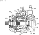
- Fig. 3 is a cross-sectional view of an example of the variable displacement pump motor.
- the first variable displacement pump motor 20 and the second variable displacement pump motor 30 may basically have the same configuration.
- the variable displacement pump motor depicted in Fig. 3 is a piston pump motor of a variable displacement swash plate type.
- the variable displacement pump motor includes a cover 161, a pump housing 168, and a driveshaft 170 axially supported by the cover 161 and the pump housing 168.
- the cover 161 is provided with a first supply/discharge passage 163 through which the hydraulic oil to be suctioned flows when the variable displacement pump motor functions as the hydraulic pump and through which the discharged hydraulic oil flows when the variable displacement pump motor functions as the hydraulic motor.
- the cover 161 is provided with a second supply/discharge passage 165 through which the discharged hydraulic oil flows when the variable displacement pump motor functions as the hydraulic pump and through which the hydraulic oil to be suctioned flows when the variable displacement pump motor functions as the hydraulic motor.
- the first supply/discharge passage 163 communicates with an unillustrated tank in which the hydraulic oil is stored.
- the second supply/discharge passage 165 communicates with the pressure chamber in the hydraulic cylinder 40.
- the second supply/discharge passage 165 communicates with the cap-side pressure chamber 47.
- the second supply/discharge passage 165 communicates with the rod-side pressure chamber 45.
- a cylinder block 180 is coupled to the driveshaft 170, and the cylinder block 180 integrally rotates with the driveshaft 170.
- a port plate 190 is provided on one end side of the cylinder block 180, and a swash plate 175 is provided on the other side of the cylinder block 180.
- a surface on the one end side of the cylinder block 180 slidably contacts the port plate 190.
- plural cylinders 182 are placed along an axial direction of the driveshaft 170.
- a piston 185 is inserted in each of the cylinders 182 in an axially movable manner, and a volume chamber 188 is configured by the cylinders 182 and the piston 185.
- the volume chamber 188 can communicate with the first supply/discharge passage 163 and the second supply/discharge passage 165, which are formed in the cover 161, via hydraulic ports 192, 194 provided in the port plate 190.
- the swash plate 175 When the variable displacement pump motor functions as the hydraulic pump, the swash plate 175 is tilted such that the first supply/discharge passage 163 in the cover 161 communicates with the volume chamber 188 in a region where the volume chamber 188 expands and that the second supply/discharge passage 165 communicates with the volume chamber 188 in a region where the volume chamber 188 contracts.
- the hydraulic oil that is stored in the tank is suctioned into the volume chamber 188 via the first supply/discharge passage 163, is then pressurized in the volume chamber 188, and is thereafter supplied via the second supply/discharge passage 165.
- a pump supply flow rate can be adjusted by controlling a tilt amount.
- variable displacement pump motor When the variable displacement pump motor functions as the hydraulic motor, the swash plate 175 is tilted such that the first supply/discharge passage 163 communicates with the volume chamber 188 in the region where the volume chamber 188 contracts and that the second supply/discharge passage 165 communicates with the volume chamber 188 in the region where the volume chamber 188 expands.
- the variable displacement pump motor is rotationally driven by using the hydraulic pressure that is discharged from the pressure chamber in the hydraulic cylinder 40, and output torque is generated by the driveshaft 170.
- Tilt (the tilt amount) of the swash plate 175 can be adjusted by a hydraulic actuator 195.
- the variable displacement pump motor of an over center type is used, and the swash plate 175 is configured to be tiltable not only in one direction but in both directions.
- a hydraulic actuator 195 is constructed of a hydraulic circuit that includes a direction selector valve and the like, selectively increases the pressure of the hydraulic oil that is supplied to either one pressure chamber of the two pressure chambers, and can thereby tilt the swash plate 175 in either one of the directions.
- the hydraulic actuator 195 supplies the hydraulic oil to the two pressure chambers in specified balance and can thereby set the tilt amount to zero. In this way, the function of the variable displacement pump motor as the hydraulic pump or the hydraulic motor can be stopped.
- the hydraulic actuator 195 which adjusts the tilt amount, is controlled by an unillustrated electronic control unit.
- the electronic control unit controls the direction selector valve and the like on the basis of an actuation direction of the boom 120, hydraulic pressures P1, P2 that are measured by the pressure detectors 28, 38 provided in the first control oil path 22 and the second control oil path 32, and the like, and thereby appropriately adjusts a tilt direction and the tilt amount of the swash plate 175.
- the motor generator 50 functions as a motor that is actuated by electric power supplied from an electric power supply 70 on the outside of the hydraulic cylinder drive device 10 and rotationally drives the driveshaft 52.
- the motor generator 50 also functions as a generator that rotates by using a rotation driving force of the driveshaft 52 and supplies the electric power to the outside of the hydraulic cylinder drive device 10, the rotation driving force being generated by the first variable displacement pump motor 20 or the second variable displacement pump motor 30 that functions as the hydraulic motor.
- the motor generator 50 is constructed of a three-phase AC motor, for example.
- the motor generator 50 generates the rotation driving force that is applied to the driveshaft 52.
- the generated rotation driving force is output in accordance with required driving forces of the first variable displacement pump motor 20 and the second variable displacement pump motor 30.
- the motor generator 50 rotates by using rotation torque of the driveshaft 52 and generates the regenerative power.
- the generated regenerative power is supplied to unillustrated electric power load equipment.
- the generated regenerative power is used as the electric power in a plant in which the boom drive system 100 is installed.
- the regenerative power maybe stored in a battery, an electrical storage device, or the like.
- the first variable displacement pump motor 20 functions as the hydraulic pump
- the second variable displacement pump motor 30 functions as the hydraulic motor. That is, in the hydraulic cylinder 40, while the hydraulic oil is supplied to the cap-side pressure chamber 47, the hydraulic oil is discharged from the rod-side pressure chamber 45.
- the electronic control unit controls the tilt amounts in the first variable displacement pump motor 20 and the second variable displacement pump motor 30 on the basis of a boom speed that is set on the outside and measurement values of the pressure detectors 28, 38 that are respectively provided in the first control oil path 22 and the second control oil path 32.
- the electronic control unit controls the tilt amounts in the first variable displacement pump motor 20 and the second variable displacement pump motor 30 such that an extending speed of the piston rod 43 matches a desired speed.
- the second variable displacement pump motor 30 functions as the hydraulic motor that rotationally drives the driveshaft 52 by using the hydraulic oil discharged from the rod-side pressure chamber 45, and thereby generates the rotation driving force for the driveshaft 52. Accordingly, the rotation driving force for the driveshaft 52, which is generated by the second variable displacement pump motor 30, can be used for the first variable displacement pump motor 20 to supply the hydraulic oil. Thus, a magnitude of the electric power of the motor generator 50 can be set low.
- the first variable displacement pump motor 20 functions as the hydraulic motor
- the second variable displacement pump motor 30 functions as the hydraulic pump. That is, while the hydraulic oil is supplied to the rod-side pressure chamber 45 in the hydraulic cylinder 40, the hydraulic oil is discharged from the cap-side pressure chamber 47.
- the electronic control unit controls the tilt amounts in the first variable displacement pump motor 20 and the second variable displacement pump motor 30 on the basis of the boom speed that is set on the outside and the measurement values of the pressure detectors 28, 38 that are respectively provided in the first control oil path 22 and the second control oil path 32.
- the electronic control unit controls the tilt amounts in the first variable displacement pump motor 20 and the second variable displacement pump motor 30 such that a retracting speed of the piston rod 43 matches a desired speed.
- the first variable displacement pump motor 20 functions as the hydraulic motor that rotationally drives the driveshaft 52 by using the hydraulic oil discharged from the cap-side pressure chamber 47, and thereby generates the rotation driving force for the driveshaft 52. Accordingly, the rotation driving force for the driveshaft 52, which is generated by the first variable displacement pump motor 20, can be used for the second variable displacement pump motor 30 to supply the hydraulic oil. Thus, the magnitude of the electric power of the motor generator 50 can be set low.
- the rotation driving force for the driveshaft 52 which is generated by the first variable displacement pump motor 20 exceeds the required rotation driving force for the second variable displacement pump motor 30 to supply the hydraulic oil
- the surplus of the rotation driving force for the driveshaft 52 which is generated by the first variable displacement pump motor 20 is converted to the electric power by the motor generator 50.
- the generated electric power is supplied to the unillustrated electric power load equipment.
- the hydraulic cylinder drive device 10 includes: the first variable displacement pump motor 20 that functions as the hydraulic pump supplying the hydraulic oil to the cap-side pressure chamber 47 in the hydraulic cylinder 40 and functions as a power unit of the motor generator 50 by using the hydraulic oil discharged from the cap-side pressure chamber 47; and the second variable displacement pump motor 30 that functions as the hydraulic pump supplying the hydraulic oil to the rod-side pressure chamber 45 in the hydraulic cylinder 40 and functions as a power unit of the motor generator 50 by using the hydraulic oil discharged from the rod-side pressure chamber 45.
- the rotation driving force generated by one of the variable displacement pump motors that functions as the hydraulic motor assists the other variable displacement pump motor to be rotationally driven as the hydraulic pump.
- an electric power amount of the motor generator 50 that is used to rotationally drive the driveshaft 52 can be reduced.
- the motor generator 50 generates the regenerative electric power by using the surplus of the rotation driving force.
- the hydraulic cylinder drive device 10 does not include the direction selector valve, the flow rate control valve, the oil cooler, or the like but has a simple configuration. Thus, cost can be cut, and the energy efficiency is improved.
- the hydraulic cylinder drive device differs from the hydraulic cylinder drive device according to the first embodiment in a point that the first variable displacement pump motor and the second variable displacement pump motor are subjected to drive control by separated motor generators.
- Fig. 4 is a circuit diagram illustrating a configuration of a hydraulic circuit in a hydraulic cylinder drive device 10A according to this embodiment.
- the hydraulic cylinder drive device 10A includes the first variable displacement pump motor 20, the second variable displacement pump motor 30, a first motor generator 50a, a second motor generator 50b, and the hydraulic cylinder 40.
- Each of the first variable displacement pump motor 20, the second variable displacement pump motor 30, and the hydraulic cylinder 40 may have the same configuration as that in the hydraulic cylinder drive device 10 according to the first embodiment.
- the first variable displacement pump motor 20 is driven by the first motor generator 50a
- the second variable displacement pump motor 30 is driven by the second motor generator 50b.
- a driveshaft 52a of the first variable displacement pump motor 20 and a driveshaft 52b of the second variable displacement pump motor 30 are independent of each other.
- the first motor generator 50a and the second motor generator 50b are electrically connected to the electric power supply 70.
- Each of the first motor generator 50a and the second motor generator 50b may have the same configuration as the motor generator in the hydraulic cylinder drive device 10 according to the first embodiment.
- the first variable displacement pump motor 20 functions as the hydraulic pump
- the second variable displacement pump motor 30 functions as the hydraulic motor.
- the first variable displacement pump motor 20 functions as the hydraulic motor
- the second variable displacement pump motor 30 functions as the hydraulic pump.
- the tilt amount in the variable displacement pump motor that functions as the hydraulic pump is controlled on the basis of the actuation direction of the boom, the boom speed, the hydraulic pressures P1, P2 that are measured by the pressure detectors 28, 38 provided in the first control oil path 22 and the second control oil path 32, and the like. That is, the unillustrated electronic control unit controls the tilt amounts in the first variable displacement pump motor 20 and the second variable displacement pump motor 30 such that the extending speed or the retracting speed of the piston rod 43 matches the desired speed.
- the variable displacement pump motor that functions as the hydraulic motor is driven by using the hydraulic oil that is discharged from the pressure chamber in the hydraulic cylinder 40, and the motor generator generates the regenerative power by using the rotation driving force for the driveshaft that is generated by said variable displacement pump motor. In this way, the rotation driving force for the driveshaft, which is generated by variable displacement pump motor functioning as the hydraulic motor, is converted to the electric power, and the converted electric power is then supplied to the unillustrated electric power load equipment.
- the hydraulic cylinder drive device 10A includes the first variable displacement pump motor 20 and the second variable displacement pump motor 30, each of which functions as the hydraulic pump or the hydraulic motor.
- the motor generator generates the regenerative power by using the rotation driving force of the variable displacement pump motor that functions as the hydraulic motor.
- the hydraulic cylinder drive device 10A according to this embodiment does not include the direction selector valve, the flow rate control valve, or the like but has a simple configuration. Thus, the cost can be cut, and the energy efficiency is improved.
- the hydraulic cylinder drive devices 10, 10A are each used in the boom drive system 100.
- the invention is not limited to such examples.
- Each of the hydraulic cylinder drive devices 10, 10A may be applied to another device to be actuated such as a hydraulic cylinder drive device that is used for a raising/lowering operation of an arm supporting a bucket of a hydraulic shovel as long as each of the hydraulic cylinder drive devices 10, 10A may apply a force in a tensile direction and a force in a compression direction to a hydraulic cylinder.
- an inverter circuit that controls the motor generators 50, 50a, 50b may be provided.
- the motor generators 50, 50a, 50b can be subjected to inverter control, responsiveness of hydraulic control is improved.
- the operation of the hydraulic cylinder 40 can be improved in a region where the hydraulic pressure in the hydraulic cylinder 40 has a high change rate.
- the motor generators 50, 50a, 50b are stopped during a stop of the system. In this way, required energy can further be reduced.
Landscapes
- Engineering & Computer Science (AREA)
- General Engineering & Computer Science (AREA)
- Mining & Mineral Resources (AREA)
- Civil Engineering (AREA)
- Structural Engineering (AREA)
- Physics & Mathematics (AREA)
- Fluid Mechanics (AREA)
- Mechanical Engineering (AREA)
- Chemical & Material Sciences (AREA)
- Analytical Chemistry (AREA)
- Fluid-Pressure Circuits (AREA)
Applications Claiming Priority (2)
| Application Number | Priority Date | Filing Date | Title |
|---|---|---|---|
| JP2015190291 | 2015-09-28 | ||
| PCT/JP2016/072738 WO2017056702A1 (ja) | 2015-09-28 | 2016-08-03 | 油圧シリンダ駆動装置 |
Publications (2)
| Publication Number | Publication Date |
|---|---|
| EP3358202A1 true EP3358202A1 (de) | 2018-08-08 |
| EP3358202A4 EP3358202A4 (de) | 2018-10-10 |
Family
ID=58423157
Family Applications (1)
| Application Number | Title | Priority Date | Filing Date |
|---|---|---|---|
| EP16850879.4A Withdrawn EP3358202A4 (de) | 2015-09-28 | 2016-08-03 | Hydraulikzylinderantriebsvorrichtung |
Country Status (5)
| Country | Link |
|---|---|
| EP (1) | EP3358202A4 (de) |
| JP (1) | JPWO2017056702A1 (de) |
| KR (1) | KR20180043350A (de) |
| CN (1) | CN108350914A (de) |
| WO (1) | WO2017056702A1 (de) |
Cited By (1)
| Publication number | Priority date | Publication date | Assignee | Title |
|---|---|---|---|---|
| WO2020035391A1 (en) * | 2018-08-16 | 2020-02-20 | Moog Italiana S.R.L. | Digital pump axis control system |
Families Citing this family (2)
| Publication number | Priority date | Publication date | Assignee | Title |
|---|---|---|---|---|
| CN108468358A (zh) * | 2018-03-15 | 2018-08-31 | 福建工程学院 | 分布式液压驱动的挖掘机及其动力系统 |
| KR102145392B1 (ko) * | 2019-07-05 | 2020-08-18 | 주식회사 예성리테일 | 공유압 실린더의 공압 및 유압 제어장치 |
Family Cites Families (10)
| Publication number | Priority date | Publication date | Assignee | Title |
|---|---|---|---|---|
| DE19600650C2 (de) * | 1996-01-10 | 2003-05-28 | Trinova Gmbh | Antrieb für einen hydraulischen doppelwirkenden Aktuator |
| JP2001090704A (ja) * | 1999-09-21 | 2001-04-03 | Tokimec Inc | 駆動装置 |
| JP2002039110A (ja) * | 2000-07-27 | 2002-02-06 | Kobelco Contstruction Machinery Ltd | 油圧シリンダ回路 |
| JP3936552B2 (ja) * | 2001-05-25 | 2007-06-27 | コベルコ建機株式会社 | 油圧シリンダ回路 |
| CA2588290A1 (en) * | 2004-12-01 | 2006-06-08 | Haldex Hydraulics Corporation | Hydraulic drive system |
| US9151019B2 (en) * | 2009-09-15 | 2015-10-06 | Sumitomo Heavy Industries, Ltd. | Hybrid type construction machine |
| CN101956405A (zh) * | 2010-07-15 | 2011-01-26 | 吉林大学 | 一种工程机械动臂下降的重力势能回收装置 |
| JP5858818B2 (ja) * | 2012-02-17 | 2016-02-10 | 日立建機株式会社 | 建設機械 |
| DE102012006981B4 (de) * | 2012-04-05 | 2019-02-21 | Schuler Pressen Gmbh | Hydraulische Presse |
| CN103671306A (zh) * | 2013-11-21 | 2014-03-26 | 中国石油化工股份有限公司 | 液压动力装置及其势能转化与操作方法 |
-
2016
- 2016-08-03 CN CN201680056289.6A patent/CN108350914A/zh active Pending
- 2016-08-03 KR KR1020187008460A patent/KR20180043350A/ko not_active Ceased
- 2016-08-03 WO PCT/JP2016/072738 patent/WO2017056702A1/ja not_active Ceased
- 2016-08-03 JP JP2017542984A patent/JPWO2017056702A1/ja active Pending
- 2016-08-03 EP EP16850879.4A patent/EP3358202A4/de not_active Withdrawn
Cited By (1)
| Publication number | Priority date | Publication date | Assignee | Title |
|---|---|---|---|---|
| WO2020035391A1 (en) * | 2018-08-16 | 2020-02-20 | Moog Italiana S.R.L. | Digital pump axis control system |
Also Published As
| Publication number | Publication date |
|---|---|
| KR20180043350A (ko) | 2018-04-27 |
| WO2017056702A1 (ja) | 2017-04-06 |
| JPWO2017056702A1 (ja) | 2018-06-14 |
| CN108350914A (zh) | 2018-07-31 |
| EP3358202A4 (de) | 2018-10-10 |
Similar Documents
| Publication | Publication Date | Title |
|---|---|---|
| US6005360A (en) | Power unit for the supply of hydraulic actuators | |
| US9809957B2 (en) | Energy recovery method and system | |
| KR20100106215A (ko) | 유압 굴삭기용 구동장치 | |
| US4761954A (en) | Fork-lift system | |
| CN104024659B (zh) | 作业机械的动力再生装置以及作业机械 | |
| CN109764027B (zh) | 具有能量回收功能的电液压作业车辆 | |
| US9476437B2 (en) | Boom driving device | |
| RU2016136704A (ru) | Погрузочно-разгрузочное транспортное средство, рассчитывающее скорость подвижного узла по скорости двигателя механизма подъёма | |
| CN1914384A (zh) | 建设机械的控制回路 | |
| CN106194584B (zh) | 静液压的线性促动器以及具有静液压的线性促动器的装置 | |
| US20160122980A1 (en) | Construction machine energy regeneration apparatus | |
| US8267378B1 (en) | Triple cylinder with auxiliary gas over oil accumulator | |
| JP2017512657A (ja) | プレス機械 | |
| CN107429714A (zh) | 建筑机械的油压驱动系统 | |
| JP5585487B2 (ja) | ハイブリッド建設機械の動力源装置 | |
| US5862663A (en) | System for raising and lowering the load support of an electric lift truck | |
| JPWO2017056702A1 (ja) | 油圧シリンダ駆動装置 | |
| KR102425742B1 (ko) | 건설기계의 제어장치 및 제어방법 | |
| JP2016109204A (ja) | ハイブリッド建設機械の制御システム | |
| US20150176617A1 (en) | Energy Recapture System for Hydraulic Elevators | |
| RU119411U1 (ru) | Электрогидравлический привод для скважинного штангового насоса | |
| JP4840263B2 (ja) | 発電システム | |
| JP4882986B2 (ja) | 液圧回路 | |
| RU119410U1 (ru) | Гидравлический привод для скважинного штангового насоса | |
| KR20110074434A (ko) | 에너지 절감형 하이브리드 윈치 구동 시스템 |
Legal Events
| Date | Code | Title | Description |
|---|---|---|---|
| STAA | Information on the status of an ep patent application or granted ep patent |
Free format text: STATUS: THE INTERNATIONAL PUBLICATION HAS BEEN MADE |
|
| PUAI | Public reference made under article 153(3) epc to a published international application that has entered the european phase |
Free format text: ORIGINAL CODE: 0009012 |
|
| STAA | Information on the status of an ep patent application or granted ep patent |
Free format text: STATUS: REQUEST FOR EXAMINATION WAS MADE |
|
| 17P | Request for examination filed |
Effective date: 20180430 |
|
| AK | Designated contracting states |
Kind code of ref document: A1 Designated state(s): AL AT BE BG CH CY CZ DE DK EE ES FI FR GB GR HR HU IE IS IT LI LT LU LV MC MK MT NL NO PL PT RO RS SE SI SK SM TR |
|
| AX | Request for extension of the european patent |
Extension state: BA ME |
|
| A4 | Supplementary search report drawn up and despatched |
Effective date: 20180910 |
|
| RIC1 | Information provided on ipc code assigned before grant |
Ipc: F15B 11/17 20060101ALI20180904BHEP Ipc: B66F 9/00 20060101ALI20180904BHEP Ipc: F15B 11/00 20060101ALI20180904BHEP Ipc: E02F 9/22 20060101ALI20180904BHEP Ipc: F15B 21/14 20060101AFI20180904BHEP |
|
| DAV | Request for validation of the european patent (deleted) | ||
| DAX | Request for extension of the european patent (deleted) | ||
| STAA | Information on the status of an ep patent application or granted ep patent |
Free format text: STATUS: EXAMINATION IS IN PROGRESS |
|
| 17Q | First examination report despatched |
Effective date: 20200117 |
|
| STAA | Information on the status of an ep patent application or granted ep patent |
Free format text: STATUS: THE APPLICATION IS DEEMED TO BE WITHDRAWN |
|
| 18D | Application deemed to be withdrawn |
Effective date: 20200603 |