EP3358287B1 - Échangeur de chaleur et dispositif à cycle de réfrigération doté de ce dernier - Google Patents
Échangeur de chaleur et dispositif à cycle de réfrigération doté de ce dernier Download PDFInfo
- Publication number
- EP3358287B1 EP3358287B1 EP15905404.8A EP15905404A EP3358287B1 EP 3358287 B1 EP3358287 B1 EP 3358287B1 EP 15905404 A EP15905404 A EP 15905404A EP 3358287 B1 EP3358287 B1 EP 3358287B1
- Authority
- EP
- European Patent Office
- Prior art keywords
- heat exchanging
- heat
- heat exchanger
- flat tubes
- exchanging portion
- Prior art date
- Legal status (The legal status is an assumption and is not a legal conclusion. Google has not performed a legal analysis and makes no representation as to the accuracy of the status listed.)
- Not-in-force
Links
Images


Classifications
-
- F—MECHANICAL ENGINEERING; LIGHTING; HEATING; WEAPONS; BLASTING
- F28—HEAT EXCHANGE IN GENERAL
- F28F—DETAILS OF HEAT-EXCHANGE AND HEAT-TRANSFER APPARATUS, OF GENERAL APPLICATION
- F28F1/00—Tubular elements; Assemblies of tubular elements
- F28F1/02—Tubular elements of cross-section which is non-circular
- F28F1/04—Tubular elements of cross-section which is non-circular polygonal, e.g. rectangular
-
- F—MECHANICAL ENGINEERING; LIGHTING; HEATING; WEAPONS; BLASTING
- F25—REFRIGERATION OR COOLING; COMBINED HEATING AND REFRIGERATION SYSTEMS; HEAT PUMP SYSTEMS; MANUFACTURE OR STORAGE OF ICE; LIQUEFACTION SOLIDIFICATION OF GASES
- F25B—REFRIGERATION MACHINES, PLANTS OR SYSTEMS; COMBINED HEATING AND REFRIGERATION SYSTEMS; HEAT PUMP SYSTEMS
- F25B39/00—Evaporators; Condensers
-
- F—MECHANICAL ENGINEERING; LIGHTING; HEATING; WEAPONS; BLASTING
- F28—HEAT EXCHANGE IN GENERAL
- F28D—HEAT-EXCHANGE APPARATUS, NOT PROVIDED FOR IN ANOTHER SUBCLASS, IN WHICH THE HEAT-EXCHANGE MEDIA DO NOT COME INTO DIRECT CONTACT
- F28D1/00—Heat-exchange apparatus having stationary conduit assemblies for one heat-exchange medium only, the media being in contact with different sides of the conduit wall, in which the other heat-exchange medium is a large body of fluid, e.g. domestic or motor car radiators
- F28D1/02—Heat-exchange apparatus having stationary conduit assemblies for one heat-exchange medium only, the media being in contact with different sides of the conduit wall, in which the other heat-exchange medium is a large body of fluid, e.g. domestic or motor car radiators with heat-exchange conduits immersed in the body of fluid
- F28D1/04—Heat-exchange apparatus having stationary conduit assemblies for one heat-exchange medium only, the media being in contact with different sides of the conduit wall, in which the other heat-exchange medium is a large body of fluid, e.g. domestic or motor car radiators with heat-exchange conduits immersed in the body of fluid with tubular conduits
- F28D1/053—Heat-exchange apparatus having stationary conduit assemblies for one heat-exchange medium only, the media being in contact with different sides of the conduit wall, in which the other heat-exchange medium is a large body of fluid, e.g. domestic or motor car radiators with heat-exchange conduits immersed in the body of fluid with tubular conduits the conduits being straight
- F28D1/0535—Heat-exchange apparatus having stationary conduit assemblies for one heat-exchange medium only, the media being in contact with different sides of the conduit wall, in which the other heat-exchange medium is a large body of fluid, e.g. domestic or motor car radiators with heat-exchange conduits immersed in the body of fluid with tubular conduits the conduits being straight the conduits having a non-circular cross-section
- F28D1/05366—Assemblies of conduits connected to common headers, e.g. core type radiators
- F28D1/05383—Assemblies of conduits connected to common headers, e.g. core type radiators with multiple rows of conduits or with multi-channel conduits
-
- F—MECHANICAL ENGINEERING; LIGHTING; HEATING; WEAPONS; BLASTING
- F28—HEAT EXCHANGE IN GENERAL
- F28D—HEAT-EXCHANGE APPARATUS, NOT PROVIDED FOR IN ANOTHER SUBCLASS, IN WHICH THE HEAT-EXCHANGE MEDIA DO NOT COME INTO DIRECT CONTACT
- F28D7/00—Heat-exchange apparatus having stationary tubular conduit assemblies for both heat-exchange media, the media being in contact with different sides of a conduit wall
- F28D7/0066—Multi-circuit heat-exchangers, e.g. integrating different heat exchange sections in the same unit or heat-exchangers for more than two fluids
-
- F—MECHANICAL ENGINEERING; LIGHTING; HEATING; WEAPONS; BLASTING
- F28—HEAT EXCHANGE IN GENERAL
- F28F—DETAILS OF HEAT-EXCHANGE AND HEAT-TRANSFER APPARATUS, OF GENERAL APPLICATION
- F28F1/00—Tubular elements; Assemblies of tubular elements
- F28F1/02—Tubular elements of cross-section which is non-circular
-
- F—MECHANICAL ENGINEERING; LIGHTING; HEATING; WEAPONS; BLASTING
- F28—HEAT EXCHANGE IN GENERAL
- F28F—DETAILS OF HEAT-EXCHANGE AND HEAT-TRANSFER APPARATUS, OF GENERAL APPLICATION
- F28F1/00—Tubular elements; Assemblies of tubular elements
- F28F1/02—Tubular elements of cross-section which is non-circular
- F28F1/022—Tubular elements of cross-section which is non-circular with multiple channels
-
- F—MECHANICAL ENGINEERING; LIGHTING; HEATING; WEAPONS; BLASTING
- F28—HEAT EXCHANGE IN GENERAL
- F28F—DETAILS OF HEAT-EXCHANGE AND HEAT-TRANSFER APPARATUS, OF GENERAL APPLICATION
- F28F1/00—Tubular elements; Assemblies of tubular elements
- F28F1/02—Tubular elements of cross-section which is non-circular
- F28F1/06—Tubular elements of cross-section which is non-circular crimped or corrugated in cross-section
-
- F—MECHANICAL ENGINEERING; LIGHTING; HEATING; WEAPONS; BLASTING
- F28—HEAT EXCHANGE IN GENERAL
- F28F—DETAILS OF HEAT-EXCHANGE AND HEAT-TRANSFER APPARATUS, OF GENERAL APPLICATION
- F28F9/00—Casings; Header boxes; Auxiliary supports for elements; Auxiliary members within casings
- F28F9/02—Header boxes; End plates
-
- F—MECHANICAL ENGINEERING; LIGHTING; HEATING; WEAPONS; BLASTING
- F28—HEAT EXCHANGE IN GENERAL
- F28D—HEAT-EXCHANGE APPARATUS, NOT PROVIDED FOR IN ANOTHER SUBCLASS, IN WHICH THE HEAT-EXCHANGE MEDIA DO NOT COME INTO DIRECT CONTACT
- F28D21/00—Heat-exchange apparatus not covered by any of the groups F28D1/00 - F28D20/00
- F28D2021/0019—Other heat exchangers for particular applications; Heat exchange systems not otherwise provided for
- F28D2021/0068—Other heat exchangers for particular applications; Heat exchange systems not otherwise provided for for refrigerant cycles
-
- F—MECHANICAL ENGINEERING; LIGHTING; HEATING; WEAPONS; BLASTING
- F28—HEAT EXCHANGE IN GENERAL
- F28F—DETAILS OF HEAT-EXCHANGE AND HEAT-TRANSFER APPARATUS, OF GENERAL APPLICATION
- F28F2210/00—Heat exchange conduits
- F28F2210/08—Assemblies of conduits having different features
Definitions
- the present invention relates to a heat exchanger and a refrigeration cycle apparatus including the heat exchanger.
- it relates to a heat exchanger as defined in the preamble of claim 1, and as disclosed on figure 3 of EP 2 333 471 A2 .
- the total surface area of refrigerant flow paths formed in a heat exchange pipe of a heat exchanger can be increased in a manner in which the diameter of each refrigerant flow path formed is decreased and the number of the refrigerant flow paths is increased in accordance with the decrease in the diameter.
- the decrease in the diameter of each refrigerant flow path enables the heat exchange performance of the heat exchanger to be improved, and the heat exchanger can have a certain level of heat exchange performance even when the heat exchanger includes no fins (finless heat exchanger). Since the finless heat exchanger includes no fins, the heat exchanger can be compact.
- a finless heat exchanger including flat heat exchange pipes (heat exchanging portions) defining refrigerant flow paths, an entrance-side header to which an end of each heat exchange pipe is connected, and an exit-side header to which the other end of each heat exchange pipe is connected has been proposed as an existing finless heat exchanger (see, for example, Patent Literature 1).
- the flat heat exchange pipes are connected to the entrance-side header and the exit-side header so as to be arranged in the longitudinal direction of the entrance-side header and the exit-side header.
- Patent Literature 1 Japanese Unexamined Patent Application Publication No. 2008-528943
- the heat exchange performance of the finless heat exchanger is improved, for example, in a manner in which distances between the adjacent heat exchanging portions are decreased and the number of the heat exchange pipes is increased accordingly. Air passes through spaces formed between the adjacent heat exchange pipes. In this manner, however, the size of each of the spaces is decreased, and the spaces are likely to be filled. When the spaces are filled, air is unlikely to pass therethrough, and the heat exchange performance is impaired.
- frost formation occurs between the heat exchange pipes in some cases.
- the spaces between the adjacent heat exchange pipes are likely to be filled with frost.
- the present invention has been accomplished to solve the above problems, and it is an object of the present invention to provide a heat exchanger that enables the heat exchange performance to be improved even when distances between flat tubes of the heat exchanging portions are not decreased, and a refrigeration cycle apparatus including the heat exchanger.
- the invention corresponds to a heat exchanger as defined in claim 1, and as specified in the dependent claims.
- the heat exchanger according to an embodiment of the present invention which has the above structure, enables the heat exchange performance to be improved even when the distances in the heat exchanging portions are not decreased.
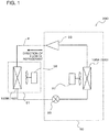
- Fig. 1 is an explanatory diagram illustrating the structure of a refrigerant circuit or other structures of a refrigeration cycle apparatus 200 including a heat exchanger 100 according to Embodiment. The structure and other features of the refrigeration cycle apparatus 200 will be described with reference to Fig. 1 .
- the heat exchanger 100 according to Embodiment has been improved upon to enable the heat exchange performance to be improved even when distances between flat tubes 1a of heat exchanging portions 1A are not decreased.
- the refrigeration cycle apparatus 200 includes an outdoor unit 50 and an indoor unit 51, for example, in the case where the refrigeration cycle apparatus 200 is an air-conditioning device.
- the outdoor unit 50 and the indoor unit 51 are connected to each other with refrigerant pipes P interposed therebetween.
- the outdoor unit 50 includes a compressor 33 that compresses refrigerant, an outdoor fan 37 that sends air and that supplies the air to the outdoor heat exchanger 100A, an outdoor heat exchanger 100A that functions as an evaporator, and an expansion device 35 that is connected to an indoor heat exchanger 100B described later and the outdoor heat exchanger 100A.
- the indoor unit 51 includes the indoor heat exchanger 100B that functions as a condenser (radiator) and an indoor fan 38 that supplies air to the indoor heat exchanger 100B.
- the outdoor heat exchanger 100A and the indoor heat exchanger 100B are each referred to as the heat exchanger 100 in some cases.
- the compressor 33 compresses and discharges the refrigerant.
- the compressor 33 is connected to the indoor heat exchanger 100B on a refrigerant discharge side and is connected to the outdoor heat exchanger 100A on a refrigerant suction side.
- Various types of compressors such as a scroll compressor and a rotary compressor can be used as the compressor 33.
- the heat exchanger 100 includes flat tubes defining refrigerant flow paths through which the refrigerant flows.
- the heat exchanger 100 does not include fins connected perpendicularly to the flat tubes. That is, the heat exchanger 100 is a so-called finless heat exchanger.
- the indoor heat exchanger 100B is connected on one side to the discharge side of the compressor 33 and is connected on the other side to the expansion device 35.
- the outdoor heat exchanger 100A is connected on one side to the suction side of the compressor 33 and is connected on the other side to the expansion device 35. The structure and other features of the heat exchanger 100 will be described later with reference to Fig. 2 .
- the indoor fan 38 forcibly draws air into the indoor unit 51 to supply the air to the indoor heat exchanger 100B.
- the indoor fan 38 is used for heat exchange between the drawn air and the refrigerant passing through the indoor heat exchanger 100B.
- the indoor fan 38 is installed in the indoor heat exchanger 100B.
- the outdoor fan 37 forcibly draws air into the outdoor unit 50 to supply the air to the outdoor heat exchanger 100A.
- the outdoor fan 37 is used for heat exchange between the drawn air and the refrigerant passing through the indoor heat exchanger 100B.
- the outdoor fan 37 is installed in the outdoor heat exchanger 100A.
- the indoor fan 38 and the outdoor fan 37 can each include, for example, an electric motor to which a shaft is connected, a boss that is rotated by the electric motor, and blades that are connected to an outer circumferential portion of the boss.
- the expansion device 35 is used to decompress the refrigerant.
- the expansion device 35 may be, for example, a capillary tube, or an electronic expansion valve that can control an opening degree.
- a gas refrigerant compressed and discharged by the compressor 33 enters the indoor heat exchanger 100B.
- the gas refrigerant that has entered the indoor heat exchanger 100B exchanges heat with the air supplied from the indoor fan 38, is condensed, and exits the indoor heat exchanger 100B.
- the refrigerant that has exited the indoor heat exchanger 100B enters the expansion device 35, is expanded by the expansion device 35, and is decompressed.
- the decompressed refrigerant enters the outdoor heat exchanger 100A, exchanges heat with outdoor air supplied from the outdoor fan 37, is vaporized, and exits the outdoor heat exchanger 100A.
- the refrigerant that has exited the outdoor heat exchanger 100A is sucked into the compressor 33.
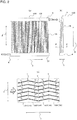
- Fig. 2 illustrates explanatory diagrams of the heat exchanger 100 according to Embodiment.
- Fig. 2(a) is a front view of the heat exchanger 100.
- Fig. 2(b) is a side view of the heat exchanger 100.
- Fig. 2(c) is a sectional view of the heat exchanging portions 1A in Fig. 2(b) taken along line A-A.
- the reduced scale of the width of each heat exchanging portion 1A in the Y-direction illustrated in Fig. 2(b) is increased for convenience of description.
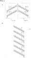
- Fig. 3 illustrates explanatory diagrams of, for example, components of the heat exchanging portions 1A of the heat exchanger 100 according to Embodiment.
- Fig. 3(a) illustrates adjacent flat tubes 1a of a heat exchanging portion 1A1 and adjacent flat tubes 1a of a heat exchanging portion 1A2 that correspond to the flat tubes 1a of the heat exchanging portion 1A1.
- four flat tubes 1a represent a minimum configuration of the heat exchanger 100.
- Fig. 3(a) illustrates two flat tubes 1a of the heat exchanging portion 1A1, and an illustration of the other four flat tubes 1a of the heat exchanging portion 1A1 is omitted.
- an illustration of the other four flat tubes 1a of the heat exchanging portion 1A2 is omitted.
- Fig. 3(b) is an enlarged view of one of the heat exchanging portions 1A illustrated in Fig. 2(c) .
- the structure of the heat exchanger 100 will be described with reference to Fig. 2 and Fig. 3 .
- the X-direction in Fig. 2 corresponds to a direction in which the flat tubes 1a are arranged.
- the Y-direction corresponds to a direction in which air passes.
- the Z-direction corresponds to the longitudinal direction of each flat tube 1a.
- the X-direction in which the flat tubes 1a of the heat exchanging portions are arranged and the Y-direction in which the air passes are perpendicular to the Z-direction corresponding to the longitudinal direction of each flat tube 1a.
- the X-direction is perpendicular to the Y-direction.
- the heat exchanger 100 is installed in the refrigeration cycle apparatus 200 such that the X-direction and the Y-direction are parallel with a horizontal plane, and the Z-direction is parallel with the gravity direction.
- the four flat tubes 1a represent the minimum configuration of the heat exchanger 100. That is, the heat exchanger 100 includes the heat exchanging portion 1A1 including two flat tubes 1a (corresponding to a first flat tube P1 and a second flat tube P2) that are stacked in parallel with each other, and the heat exchanging portion 1A2 including two flat tubes 1a (corresponding to a third flat tube P3 and a fourth flat tube P4) that are stacked in parallel with each other.
- the first flat tube P1 and the third flat tube P3 are connected to each other.
- the second flat tube P2 and the fourth flat tube P4 are connected to each other.
- the first flat tube P1 and the third flat tube P3 have a correlation therebetween in the Y-direction.
- the second flat tube P2 and the fourth flat tube P4 have a correlation therebetween in the Y-direction.
- the first flat tube P1 and the second flat tube P2 have a correlation therebetween in the X-direction.
- the third flat tube P3 and the fourth flat tube P4 have a correlation therebetween in the X-direction.
- the first flat tube P1, the second flat tube P2, the third flat tube P3, and the fourth flat tube P4 are described herein to describe the minimum configuration.
- the first flat tube P1, the second flat tube P2, the third flat tube P3, and the fourth flat tube P4 correspond to the flat tubes 1a in, for example, Fig. 2 .
- the heat exchanger 100 includes a first header 4 defining a fluid flow path D1 through which fluid flows, a second header 5 that defines a fluid flow path D2 through which fluid flows and that is paired with the first header 4, and the heat exchanging portions 1A including the flat tubes 1a each defining fluid flow paths F.
- the heat exchanging portions 1A represent the heat exchanging portion 1A1, the heat exchanging portion 1A2, a heat exchanging portion 1A3, and a heat exchanging portion 1A4.
- the heat exchanger 100 is formed such that protruding portions (bulges) and recessed portions (depressions) alternate when viewed in a cross-section perpendicular to the fluid flow paths F.
- the protruding portions when viewed from a surface side are recessed portions when viewed from the other surface side.
- the first header 4 is an elongated tubular member extending in the X-direction and defines the fluid flow path D1 through which fluid flows.
- the lower end of each heat exchanging portion 1A is connected to the first header 4.
- the first header 4 is an inflow-side header that fluid supplied from, for example, the compressor 33 enters.
- the first header 4 is oriented, for example, in parallel with the horizontal direction.
- the second header 5 is an elongated tubular member extending in the X-direction and defines the fluid flow path D2 through which fluid flows.
- the upper end of each heat exchanging portion 1A is connected to the second header 5.
- the second header 5 is an outflow-side header to which the fluid that has passed through the first header 4 and the heat exchanging portions 1A is supplied.
- the second header 5 is oriented, for example, in parallel with the horizontal direction.
- each heat exchanging portion 1A the flat tubes 1a are stacked in parallel with each other, and fluid (air) passes between the adjacent flat tubes 1a.
- six flat tubes 1a are arranged in the X-direction.
- Each heat exchanging portion 1A is connected at an end thereof to the first header 4 and is connected at the other end thereof to the second header 5.
- the heat exchanger 100 is vertically oriented in the outdoor unit 50. For this reason, the lower end of the heat exchanger 100 is connected to the first header 4, and the upper end thereof is connected to the second header 5. As illustrated in Fig. 2(a) and Fig.
- the heat exchanging portions 1A are arranged in the Y-direction. That is, the heat exchanging portion 1A1 is arranged on the most upstream side in the direction of airflow, the heat exchanging portion 1A2 is arranged downstream of the heat exchanging portion 1A1 in the direction of airflow, the heat exchanging portion 1A3 is arranged downstream of the heat exchanging portion 1A2 in the direction of airflow, and the heat exchanging portion 1A4 is arranged downstream of the heat exchanging portion 1A3 in the direction of airflow.
- each flat tube 1a of the heat exchanging portions 1A defines the fluid flow paths F through which fluid flows.
- the flat tubes 1a of one of the heat exchanging portions 1A are oriented crosswise in the direction in which the flat tubes 1a of the other heat exchanging portion 1 B are oriented.
- the flat tubes 1a of one of the heat exchanging portions and the flat tubes 1a of the other heat exchanging portion represent the flat tubes 1a of the adjacent heat exchanging portions 1A.
- the heat exchanging portion 1A1 is the one of the heat exchanging portions 1A
- the heat exchanging portion 1A2 is the other heat exchanging portion 1B.
- the flat tubes 1a oriented crosswise will now be described.
- the flat tubes 1a of the heat exchanging portion 1A2 adjacent to the heat exchanging portion 1A1 are oriented crosswise in the direction in which the corresponding flat tubes 1a of the heat exchanging portion 1A1 are oriented.
- the transverse direction of each flat tube 1a of the heat exchanging portion 1A1 is parallel with the direction in which the fluid flow paths F are arranged, and the transverse direction of each flat tube 1a of the heat exchanging portion 1A1 intersects the transverse direction of each flat tube 1a of the heat exchanging portion 1A2. Because of the intersection, the transverse direction of each flat tube 1a of the heat exchanging portion 1A1 is not parallel with the transverse direction of each flat tube 1a of the heat exchanging portion 1A2.
- the same structure as the above structure of the heat exchanging portion 1A1 and the heat exchanging portion 1A2 can be described in the case of the heat exchanging portion 1A2 and the heat exchanging portion 1A3 and in the case of the heat exchanging portion 1A3 and the heat exchanging portion 1A4. That is, the flat tubes 1a of one of the adjacent heat exchanging portions 1A are oriented crosswise in the direction in which the flat tubes 1a of the other heat exchanging portion 1A are oriented.
- the transverse direction of each flat tube 1a of the heat exchanging portion 1A1 is parallel with the transverse direction of each flat tube 1a of the heat exchanging portion 1A3
- the transverse direction of each flat tube 1a of the heat exchanging portion 1A2 is parallel with the transverse direction of each flat tube 1a of the heat exchanging portion 1A4.
- the adjacent flat tubes 1a are coupled with each other to integrally form the heat exchanging portions 1A.
- the first flat tube P1 and the third flat tube P3 are connected to (coupled with) each other, and the second flat tube P2 and the fourth flat tube P4 are connected to (coupled with) each other.
- downstream end portions of the flat tubes 1a of the heat exchanging portion 1A1 of the heat exchanger 100 are connected to (coupled with) upstream end portions of the flat tubes 1a of the heat exchanging portion 1A2.
- downstream end portions of the flat tubes 1a of the heat exchanging portion 1A2 are connected to (coupled with) upstream end portions of the flat tubes 1a of the heat exchanging portion 1A3
- downstream end portions of the flat tubes 1a of the heat exchanging portion 1A3 are connected to (coupled with) upstream end portions of the flat tubes 1a of the heat exchanging portion 1A4.
- bent portions of the heat exchanger 100 correspond to parts of the heat exchanging portions 1A that intersect each other.
- the flat tubes 1a of the adjacent heat exchanging portions 1A correspond to the connected portions.
- the parts of the heat exchanging portions 1A that intersect each other correspond to tip portions T of the heat exchanger 100.
- the heat exchanger 100 includes a first heat exchanging portion including the first and second flat tubes P1 and P2 stacked in parallel with each other and spaced from each other to allow fluid to pass between the first and second flat tubes P1 and P2, and a second heat exchanging portion including the third and fourth flat tubes P3 and P4 stacked in parallel with each other, spaced from each other to allow fluid to pass between the third and fourth flat tubes P3 and P4, and oriented crosswise to the direction in which the first and second flat tubes P1 and P2 are oriented.
- the second heat exchanging portion is arranged downstream of the first heat exchanging portion with respect to flow of the fluid.
- the first heat exchanging portion and the second heat exchanging portion represent the adjacent heat exchanging portions. That is, the first heat exchanging portion and the second heat exchanging portion represent the heat exchanging portion 1A1 and the heat exchanging portion 1A2. Moreover, the first heat exchanging portion and the second heat exchanging portion represent the heat exchanging portion 1A2 and the heat exchanging portion 1A3. Furthermore, the first heat exchanging portion and the second heat exchanging portion represent the heat exchanging portion 1A3 and the heat exchanging portion 1A4.
- the heat exchanger 100 includes the first heat exchanging portion and the second heat exchanging portion as above, the area of heat exchange between the fluid flowing through the heat exchanging portions 1A and the air passing through the heat exchanging portions 1A can be larger than that in a heat exchanger including a single heat exchanging portion.
- the air flowing through the heat exchanger 100 meanders while passing through the flat tubes 1a of the heat exchanging portions 1A, and is agitated while passing through the heat exchanging portions 1A. This improves a heat transfer coefficient.
- the heat exchanger 100 has an increased area of heat exchange and an improved heat transfer coefficient as above and thus enables the heat exchange performance to be improved without a measure of, for example, decreasing the distances between the flat tubes 1a of each heat exchanging portion 1A that are adjacent to each other in the X-direction.
- FIG. 7 is a perspective view of an existing heat exchanger.
- an existing heat exchanger 500 includes a single heat exchanging portion 1A. Fluid flow paths are formed in the heat exchanging portion 1A to improve the heat exchange performance.
- the distances between the flat tubes 1a included in the heat exchanging portion 1A need to be decreased to further improve the heat exchange performance.
- air is more unlikely to pass due to frost formation, and there is a possibility that the accuracy of assembly that is required in manufacturing increases and the manufacturing cost increases.
- the heat exchanger 100 according to Embodiment can avoid these disadvantages.
- the second header 5 on the side on which the fluid exits is disposed above the first header 4 on the side on which the fluid enters.
- the heat exchanging portions 1A are oriented in parallel with the gravity direction. For this reason, the fluid supplied to the heat exchanger 100 moves from the lower side to the upper side, the distribution of the fluid to the heat exchanging portions 1A is likely to be uniform, and the heat exchange performance is improved.
- the fluid flows down preferentially from the flat tube 1a near a fluid inlet of the first header 4 but is unlikely to flow to the flat tube 1a far from the fluid inlet.
- the distribution of the fluid to the heat exchanging portions 1A is non-uniform, and there is a possibility that the heat exchange performance is impaired.
- the refrigeration cycle apparatus 200 including the heat exchanger 100 according to Embodiment avoids these disadvantages, and the heat exchange performance is improved.
- the heat exchanger 100 according to Embodiment is a finless heat exchanger that does not include fins connected perpendicularly to the heat exchanging portions 1A (heat exchange pipes).
- a heat exchanger including fins has thermal contact resistance between the heat exchange pipes and the fins and the resistance of the fins due to heat conduction.
- the heat exchanger 100 according to Embodiment is the finless heat exchanger, which does not have the above thermal contact resistance between the heat exchange pipes and the fins and the resistance of the fins due to heat conduction, the heat exchange performance is improved.
- the heat exchanger 100 In the case where the heat exchanger 100 is used as the evaporator, condensed water flows down along the heat exchanging portions 1A oriented in parallel with the gravity direction.
- the heat exchanger 100 according to Embodiment can thus increase a drainage capacity.
- the heat exchanger 100 has an increased drainage capacity and can inhibit an ice layer to be formed on a lower portion of the heat exchanger 100, for example, during defrosting operation.
- the adjacent heat exchanging portions 1A of the heat exchanger 100 according to Embodiment are arranged such that the transverse directions of the flat tubes 1a intersect each other, and the strength thereof increases accordingly.
- the second header 5 is disposed on the upper side of the heat exchanging portions 1A, and the weight of the second header 5 is applied to the heat exchanging portions 1A.
- the adjacent heat exchanging portions 1A of the heat exchanger 100 according to Embodiment are oriented crosswise, buckling due to the weight of the second header, for example, can be avoided.
- the refrigeration cycle apparatus 200 including the heat exchanger 100 according to Embodiment described by way of example is an air-conditioning device.
- the refrigeration cycle apparatus is not limited thereto and may be, for example, a refrigerator.
- a refrigerant such as R410A, R32, or HFO1234yf can be used as a working fluid.
- refrigerant is used as the fluid.
- the fluid is not limited thereto and may be, for example, a fluid such as water or brine.
- air and refrigerant are used as the fluid. That is, refrigerant is a first fluid, and air is a second fluid.
- the first fluid and the second fluid are not limited thereto and may be other gases, liquids, or gas-liquid mixture fluids.
- any refrigerating machine oil such as mineral oil, alkylbenzene oil, ester oil, ether oil, and fluorinated oil can be used irrespective of the solubility of the oil in refrigerant.
- the refrigeration cycle apparatus 200 including the heat exchanger 100 according to Embodiment includes no four-way valve and is used for heating only, but may include a four-way valve to switch cooling and heating.
- the heat exchanger 100 is used as, but not limited to, the outdoor heat exchanger 100A and the indoor heat exchanger 100B.
- the same effects can be achieved even when the heat exchanger 100 is used as either the outdoor heat exchanger or the indoor heat exchanger. That is, the refrigeration cycle apparatus 200 including the heat exchanger 100 according to Embodiment has improved energy efficiency because of the heat exchanger 100.
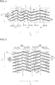
- Fig. 4 illustrates a first modification to the heat exchanger 100 according to Embodiment. As illustrated in Fig. 4 , angles at which the adjacent heat exchanging portions 1B are oriented crosswise may differ between the upstream side and the downstream side in the direction of airflow. The lengths of the flat tubes 1a in the transverse direction that are included in the heat exchanging portions 1B may differ from each other.
- the heat exchanger 100 according to the first modification includes a plurality of heat exchanging bodies.
- the heat exchanger 100 includes a heat exchanging body 10B, a heat exchanging body 20B, and a heat exchanging body 30B.
- the heat exchanging body 20B is arranged downstream of the heat exchanging body 10B in the direction of airflow.
- the heat exchanging body 30B is arranged downstream of the heat exchanging body 20B in the direction of airflow.
- the heat exchanging body 10B includes heat exchanging portions 1B.
- the heat exchanging body 10B includes a heat exchanging portion 1B1 and a heat exchanging portion 1B2 according to the first modification.
- the heat exchanging body 20B includes heat exchanging portions 1B and includes a heat exchanging portion 1B3 and a heat exchanging portion 1B4 according to the first modification.
- the heat exchanging body 30B includes heat exchanging portions 1B and includes a heat exchanging portion 1B5 and a heat exchanging portion 1B6 according to the first modification.
- the heat exchanging body 10B and the heat exchanging body 20B correspond to a first heat exchanging body and a second heat exchanging body.
- the heat exchanging body 20B and the heat exchanging body 30B correspond to a first heat exchanging body and a second heat exchanging body.
- the heat exchanging body 10B and the heat exchanging body 30B correspond to a first heat exchanging body and a second heat exchanging body.
- the heat exchanger 100 according to the first modification includes, for example, the six heat exchanging portions 1B.
- the heat exchanger 100 according to the first modification includes tip portions T corresponding to parts of the heat exchanging portions 1B that intersect each other when viewed in a section perpendicular to the fluid flow paths F.
- the lengths of the flat tubes 1a in the transverse direction that are included in the heat exchanging portions 1B located on the side (downstream side in the direction of airflow) on which air exits are larger than those in the heat exchanging portions 1B located on the side (upstream side in the direction of airflow) on which the air that exchanges heat with the fluid enters.
- angles formed between the Y-direction and the flat tubes 1a differ from each other.
- the heat exchanging portion 1B1, the heat exchanging portion 1B2, the heat exchanging portion 1B3, and the heat exchanging portion 1B4 are nearer than the heat exchanging portion 1B5 and the heat exchanging portion 1B6 to the upstream side in the direction of airflow.
- the heat exchanging portion 1B1, the heat exchanging portion 1B2, the heat exchanging portion 1B3, and the heat exchanging portion 1B4 are referred to as upstream heat exchanging portions
- the heat exchanging portion 1B5 and the heat exchanging portion 1B6 are referred to as downstream heat exchanging portions.
- the upstream heat exchanging portions include the heat exchanging body 10B and the heat exchanging body 20B.
- the downstream heat exchanging portions include the heat exchanging body 10B.
- angles formed between the Y-direction and the flat tubes 1a of the upstream heat exchanging portions are larger than the angles formed between the Y-direction and the flat tubes 1a of the downstream heat exchanging portions.
- angles formed between the Y-direction and the flat tubes 1a are also referred to simply as angles.
- the heat exchanger 100 functions as the evaporator, and frost formation occurs in the heat exchanger 100, defrosting operation, in which the direction of the flow of the refrigerant through the refrigerant circuit is reversed to supply the heated refrigerant to the heat exchanger 100, enables frost attached on the heat exchanging portions 1B on the upstream side in the direction of airflow to be efficiently removed.
- the angles ⁇ 2 formed between the Y-direction and the flat tubes 1a of the downstream heat exchanging portions are smaller than the angles ⁇ 1 formed between the Y-direction and the flat tubes 1a of the upstream heat exchanging portions, an increase in airflow resistance can be avoided. That is, in the case where the number of the heat exchanging portions 1B is increased, and the number of the tip portions T of the heat exchanger 100 is increased, the airflow resistance increases although the area of heat exchange can be increased. In view of this, in the heat exchanger 100 according to the first modification, the angles on the downstream side in the direction of airflow are made smaller to avoid the increase in the airflow resistance.
- the heat exchanger 100 according to the first modification enables frost to be efficiently removed and enables an increase in the airflow resistance to be avoided as above.
- the distances between the adjacent flat tubes 1a of the heat exchanging portions 1B of the upstream heat exchanging portions are larger than the distances between the flat tubes 1a of the heat exchanging portions 1 B of the downstream heat exchanging portions.
- the distances W1 in the heat exchanging portion 1B1 located on the side on which air enters are larger than the distances W2 in the heat exchanging portion 1B1 located on the side on which the air exits. This increases the area of contact between each heat exchanging portion 1B and frost on the upstream side in the direction of airflow, where frost is particularly likely to form, and enables the frost to be efficiently removed in the heat exchanger 100 according to the first modification.
- the lengths of the first flat tube P1 and the second flat tube P2 of the second heat exchanging body in the transverse direction are larger than the lengths of the first flat tube P1 and the second flat tube P2 of the first heat exchanging body
- the lengths of the third flat tube P3 and the fourth flat tube P4 of the second heat exchanging body in the transverse direction are larger than the lengths of the third flat tube P3 and the fourth flat tube P4 of the first heat exchanging body.
- angles formed between the Y-direction and the flat tubes 1a of the heat exchanging portions 1B on the upstream side in the direction of airflow are larger than the angles formed between the Y-direction and the flat tubes 1a of the heat exchanging portions 1B on the downstream side in the direction of airflow, and the number of the tip portions T is increased.
- the heat exchanger 100 according to the first modification enables frost to be efficiently removed and enables an increase in the airflow resistance to be avoided.
- the distances (intervals) between the adjacent flat tubes 1a of the heat exchanging portions 1B on the upstream side in the direction of airflow are larger than those in the heat exchanging portions 1B on the downstream side in the direction of airflow. For this reason, the area of contact between each heat exchanging portion 1B and frost can be increased, and the frost can be efficiently removed.
- Fig. 5 illustrates a second modification to the heat exchanger 100 according to Embodiment.
- adjacent heat exchanging portions 1C are not coupled with each other, and the heat exchanging portions 1C are separate from each other. That is, regarding the minimum configuration of the heat exchanger 100, the first flat tube P1 and the third flat tube P3 are separate from each other, and the second flat tube P2 and the fourth flat tube P4 are separate from each other.
- the second modification will now be described in detail.
- the heat exchanger 100 includes heat exchanging bodies.
- the heat exchanger 100 includes a first heat exchanging body 10C and a second heat exchanging body 20C.
- the second heat exchanging body 20C is arranged downstream of the first heat exchanging body 10C in the direction of airflow.
- the first heat exchanging body 10C includes heat exchanging portions 1C and includes a heat exchanging portion 1C1 and a heat exchanging portion 1C2 according to the second modification.
- the second heat exchanging body 20C includes heat exchanging portions 1C and includes a heat exchanging portion 1C3 and a heat exchanging portion 1C4 according to the second modification.
- the heat exchanger 100 according to the second modification includes the (four) heat exchanging portions 1C that are separate from each other. Each heat exchanging portion 1C includes seven flat tubes 1a that are stacked in parallel with each other.
- the heat exchanger 100 according to the second modification includes the heat exchanging portion 1C1, the heat exchanging portion 1C2 arranged downstream of the heat exchanging portion 1C1 in the direction of airflow, the heat exchanging portion 1C3 arranged downstream of the heat exchanging portion 1C2 in the direction of airflow, and the heat exchanging portion 1C4 arranged downstream of the heat exchanging portion 1C3 in the direction of airflow.
- the adjacent heat exchanging portions 1C are arranged at predetermined intervals. That is, the heat exchanging portions 1C are spaced from each other to allow air to pass therebetween.
- the flat tubes 1a adjacent to each other in the Y-direction are arranged at predetermined intervals. That is, spaces S1 are formed between the flat tubes 1a of the heat exchanging portion 1C1 and the flat tubes 1a of the heat exchanging portion 1C2.
- Spaces S2 are formed between the flat tubes 1a of the heat exchanging portion 1C2 and the flat tubes 1a of the heat exchanging portion 1C3.
- Spaces S3 are formed between the flat tubes 1a of the heat exchanging portion 1C3 and the flat tubes 1a of the heat exchanging portion 1C4.
- spaces S1 the spaces S2, and the spaces S3 are also referred to simply as spaces S.
- the spaces S1 are formed between the flat tubes 1a of the heat exchanging portion 1C1 and the flat tubes 1a of the heat exchanging portion 1C2 in the following manner.
- Upstream end portions of the flat tubes 1a of the heat exchanging portion 1C2 in the direction of airflow are shifted so as to cover downstream end portions of the flat tubes 1a of the heat exchanging portion 1C1.
- the upstream end portions of the flat tubes 1a of the heat exchanging portion 1C2 in the direction of airflow are shifted in the X-direction based on the positions of the downstream end portions of the flat tubes 1a of the heat exchanging portion 1C1 and are shifted in a direction toward the flat tubes 1a of the heat exchanging portion 1C1.
- the direction toward the flat tubes 1a of the heat exchanging portion 1C1 is parallel with the Y-direction.
- the spaces S1 are thus formed between the end portions of the flat tubes 1a of the heat exchanging portion 1C1 and the end portions of the flat tubes 1a of the heat exchanging portion 1C2.
- the heat exchanging portions 1C are arranged such that the spaces S located on the downstream side in the direction of airflow are larger than the spaces S located on the upstream side in the direction of airflow. That is, in the heat exchanger 100 according to the second modification, the heat exchanging portion 1C1, the heat exchanging portion 1C2, and the heat exchanging portion 1C3 are arranged such that the spaces S2 are larger than the spaces S1, and the heat exchanging portion 1C2, the heat exchanging portion 1C3, and the heat exchanging portion 1C4 are arranged such that the spaces S3 are larger than the spaces S2.
- the relation of spaces S1 ⁇ spaces S2 ⁇ spaces S3 holds.
- the heat exchanging bodies of the heat exchanger 100 according to the second modification include the first heat exchanging body 10C having the spaces S1, and the second heat exchanging body 20C that has the spaces S3 larger than the spaces S1 of the first heat exchanging body 10C and that is arranged downstream of the first heat exchanging body 10C in the direction of the flow of the fluid.
- the spaces S2 that are larger than the spaces S1 and smaller than the spaces S3 are formed between the first heat exchanging body 10C and the second heat exchanging body 20C.
- the air that has entered the flat tubes 1a of the heat exchanging portion 1C1 exchanges heat with the fluid flowing through the flat tubes 1a, is heated, and exchanges heat with, for example, the fluid flowing through the flat tubes 1a of the heat exchanging portion 1C2 on the downstream side. That is, heat is exchanged between the heated air and the fluid flowing through the flat tubes 1a of the heat exchanging portion 1C2, and this results in a reduction in the heat-exchange efficiency.
- air that is not heated enters the flat tubes 1a of the heat exchanging portion 1C2 from the spaces S1, and this inhibits the heat-exchange efficiency from being reduced.
- the spaces S3 are formed on the downstream side in the direction of airflow, and thus, the airflow resistance of the air passing through the heat exchanger 100 can be decreased.
- the spaces S1 are formed in the heat exchanging portions 1C on the upstream side in the direction of airflow.
- the spaces S1 are likely to be blocked due to the frost.
- the spaces S3, which are larger than the spaces S1 are unlikely to be blocked. Consequently, the airflow resistance can be inhibited from increasing even when the heat exchanger 100 functions as the evaporator.
- the velocity Q2 of the air flowing along a middle position between the adjacent heat exchanging portions 1C is higher than the velocity Q1 of the air flowing near each heat exchanging portion 1C.
- the flat tubes 1a are arranged such that the spaces S, such as the spaces S1, are formed.
- the upstream end portions of the flat tubes 1a of the heat exchanging portion 1C4 in the direction of airflow are located between the downstream end portions of the adjacent flat tubes 1a of the heat exchanging portion 1C3 in the direction of airflow.
- the upstream end portions of the flat tubes 1a of the heat exchanging portion 1C4 in the direction of airflow are arranged at positions at which the flow velocity of the air is high, and the efficiency of heat-exchange between the air and the fluid flowing through the flat tubes 1a of the heat exchanging portion 1 C4 is improved accordingly.
- the same is true for the relationship between the flat tubes 1a of the heat exchanging portion 1 C1 and the flat tubes 1a of the heat exchanging portion 1C2, and for the relationship between the flat tubes 1a of the heat exchanging portion 1C2 and the flat tubes 1a of the heat exchanging portion 1C3, and likewise, the heat-exchange efficiency of the heat exchanger 100 is improved.
- the heat exchanger 100 according to the third modification thus enables the heat-exchange efficiency to be improved.
- Fig. 6 illustrates a third modification to the heat exchanger 100 according to Embodiment.
- the third modification corresponds to a combination of Embodiment and the second modification.
- the heat exchanger 100 includes heat exchanging bodies.
- the heat exchanger 100 includes a first heat exchanging body 10D and a second heat exchanging body 20D.
- the second heat exchanging body 20D is arranged downstream of the first heat exchanging body 10D in the direction of airflow.
- the first heat exchanging body 10D includes heat exchanging portions 1D and includes a heat exchanging portion 1D1 and a heat exchanging portion 1D2 according to the third modification.
- the second heat exchanging body 20D includes heat exchanging portions 1D and includes a heat exchanging portion 1D3 and a heat exchanging portion 1D4 according to the third modification.
- the heat exchanger 100 includes the first heat exchanging body 10D that is integrally formed such that the heat exchanging portion 1D1 and the heat exchanging portion 1D2 are coupled with each other, and the second heat exchanging body 20D including the heat exchanging portion 1D3 and the heat exchanging portion 1D4.
- the heat exchanging portion 1D3 and the heat exchanging portion 1D4 are separate from each other.
- the first heat exchanging body 10D is integrally formed such that the flat tubes 1a adjacent to each other in the Y-direction are coupled with each other.
- spaces S are formed between the flat tubes 1a adjacent to each other in the Y-direction.
- spaces S2 are formed between the first heat exchanging body 10D and the second heat exchanging body 20D.
- Spaces S3 larger than the spaces S2 are formed between the flat tubes 1a of the second heat exchanging body 20D. That is, the heat exchanging portion 1D3 forming a part of the second heat exchanging body 20D is arranged such that the spaces S2 are formed between the heat exchanging portion 1D3 and the heat exchanging portion 1D2.
- the heat exchanging portion 1D4 forming the other part of the second heat exchanging body 20D is arranged such that the spaces S3 larger than the spaces S2 are formed between the heat exchanging portion 1D4 and the heat exchanging portion 1D3.
- the first heat exchanging body 10D is not limited to the structure in which two flat tubes 1a (two heat exchanging portions 1D) are coupled with each other and may include three or more flat tubes 1a (three or more heat exchanging portions 1D) that are coupled with each other.
- the heat exchanger 100 according to the third modification includes the first heat exchanging body 10D including the first flat tube P1 and the third flat tube P3 that are coupled with each other and the third flat tube P3 and the fourth flat tube P4 that are coupled with each other, and the second heat exchanging body 20D that is arranged downstream of the first heat exchanging body 10D in the direction of the flow of the fluid and that includes the first flat tube P1 and the third flat tube P3 that are separate from each other and the third flat tube P3 and the fourth flat tube P4 that are separate from each other.
- the effects of the heat exchanger 100 according to Embodiment and the effects of the heat exchanger 100 according to the second modification are thus achieved.
- the spaces S2 may be formed between the first heat exchanging body 10D and the second heat exchanging body 20D.
- the spaces S3 larger than the spaces S2 may be formed between the heat exchanging portion 1D3 and the heat exchanging portion 1D4 of the second heat exchanging body 20D. This enables the airflow resistance on the downstream side in the direction of airflow to be decreased.
- the heat exchanging portions are arranged such that all the adjacent heat exchanging portions are oriented crosswise.
- the heat exchanger 100 is not limited thereto.
- the heat exchanger 100 may include two heat exchanging portions that are not oriented crosswise.
Landscapes
- Engineering & Computer Science (AREA)
- Physics & Mathematics (AREA)
- Thermal Sciences (AREA)
- Mechanical Engineering (AREA)
- General Engineering & Computer Science (AREA)
- Geometry (AREA)
- Heat-Exchange Devices With Radiators And Conduit Assemblies (AREA)
- Details Of Heat-Exchange And Heat-Transfer (AREA)
Claims (8)
- Echangeur de chaleur comprenant :une pluralité de corps d'échange de chaleur comprenant un premier corps d'échange de chaleur (10B) et un second corps d'échange de chaleur (20B), les premier et second corps d'échange de chaleur comprenant chacun une première partie d'échange de chaleur comprenant des premier et deuxième tubes plats (P1, P2) empilés parallèlement entre eux pour permettre le passage du fluide entre les premier et deuxième tubes plats (P1, P2) ; etune seconde partie d'échange de chaleur comprenant des troisième et quatrième tubes plats (P3, P4) empilés parallèlement entre eux pour permettre le passage du fluide entre les troisième et quatrième tubes plats (P3, P4),le second corps d'échange de chaleur (20B) étant agencé en aval du premier corps d'échange de chaleur (10B) dans une direction de l'écoulement du fluide,le premier corps d'échange de chaleur (10B) et le second corps d'échange de chaleur (20B) étant configurés de sorte que :le troisième tube plat (P3) de la seconde partie d'échange de chaleur est orienté transversalement par rapport au premier tube plat (P1) de la première partie d'échange de chaleur dans une section transversale perpendiculaire à une direction longitudinale du troisième tube plat (P3),le quatrième tube plat (P4) de la seconde partie d'échange de chaleur est orienté transversalement par rapport au deuxième tube plat (P2) de la première partie d'échange de chaleur dans une section transversale perpendiculaire à une direction longitudinale du quatrième tube plat (P4),l'échangeur de chaleur étant caractérisé en ce que les longueurs des premier et deuxième tubes plats (P1, P2) du second corps d'échange de chaleur (20b) dans une direction transversale sont plus importantes que les longueurs des premier et deuxième tubes plats (P1, P2) du premier corps d'échange de chaleur (10B) dans la direction transversale,en ce que les angles formés entre les premier et deuxième tubes plats (P1, P2) du second corps d'échange de chaleur (20B) et la direction de l'écoulement du fluide sont inférieurs aux angles formés entre les premier et deuxième tubes plats (P1, P2) du premier corps d'échange de chaleur (10B) et la direction de l'écoulement du fluide,en ce que les longueurs des troisième et quatrième tubes plats (P3, P4) du second corps d'échange de chaleur (20B) dans la direction transversale sont supérieures aux longueurs des troisième et quatrième tubes plats (P3, P4) du premier corps d'échange de chaleur (10B) dans la direction transversale, eten ce que les angles formés entre les troisième et quatrième tubes plats (P3, P4) du second corps d'échange de chaleur (20B) et la direction de l'écoulement du fluide sont inférieurs aux angles formés entre les troisième et quatrième tube plats (P3, P4) du premier corps d'échange de chaleur (10B) et la direction de l'écoulement du fluide.
- Echangeur de chaleur selon la revendication 1,
dans lequel le premier corps d'échange de chaleur (10B) et le second corps d'échange de chaleur (20B) sont configurés de sorte que les premier et troisième tubes plats (P1, P3) sont couplés entre eux, et les deuxième et quatrième tubes plats (P2, P4) sont couplés entre eux. - Echangeur de chaleur selon la revendication 1,
dans lequel le premier corps d'échange de chaleur (10C) et le second corps d'échange de chaleur (20C) sont configurés de sorte que les premier et troisième tubes plats (P1, P3) sont séparés l'un de l'autre, et les deuxième et quatrième tubes plats (P2, P4) sont séparés l'un de l'autre. - Echangeur de chaleur selon la revendication 3,
dans lequel le premier corps d'échange de chaleur (10C) est configuré de sorte qu'un premier espace est formé entre les premier et troisième tubes plats (P1, P3) et entre les deuxième et quatrième tubes plats (P2, P4) et le second corps d'échange de chaleur (20C) est configuré de sorte qu'un deuxième espace est formé entre les premier et troisième tubes plats (P1, P3) et entre les deuxième et quatrième tubes plats (P2, P4). - Echangeur de chaleur selon la revendication 4,
dans lequel un troisième espace est formé entre le troisième tube plat (P3) du premier corps d'échange de chaleur (10C) et le premier tube plat (P1) du second corps d'échange de chaleur (20B) et entre le quatrième tube plat (P4) du premier corps d'échange de chaleur (10B) et le deuxième tube plat (P2) du second corps d'échange de chaleur (20C),
dans lequel le premier espace est supérieur au troisième espace et le troisième espace est supérieur au deuxième espace. - Echangeur de chaleur selon la revendication 1, dans lequel, dans le premier corps d'échange de chaleur (10D), les premier et troisième tubes plats (P1, P3) sont couplés entre eux et les deuxième et quatrième tubes plats (P2, P4) sont couplés entre eux, et dans le second corps d'échange de chaleur (20D), les premier et troisième tubes plats (P1, P3) sont séparés l'un de l'autre et les deuxième et quatrième tubes plats (P2, P4) sont séparés l'un de l'autre.
- Echangeur de chaleur selon l'une quelconque des revendications 1 à 6,
dans lequel le premier corps d'échange de chaleur (10B) et le second corps d'échange de chaleur (20B) sont configurés de sorte que le premier tube plat (P1), le deuxième tube plat (P2), le troisième tube plat (P3) et le quatrième tube plat (P4) ne comprennent pas d'ailette. - Appareil de cycle de réfrigération comprenant :l'échangeur de chaleur selon l'une quelconque des revendications 1 à 7,dans lequel les parties d'échange de chaleur sont orientés parallèlement à une direction de gravité.
Applications Claiming Priority (1)
| Application Number | Priority Date | Filing Date | Title |
|---|---|---|---|
| PCT/JP2015/077788 WO2017056250A1 (fr) | 2015-09-30 | 2015-09-30 | Échangeur de chaleur et dispositif à cycle de réfrigération doté de ce dernier |
Publications (3)
| Publication Number | Publication Date |
|---|---|
| EP3358287A1 EP3358287A1 (fr) | 2018-08-08 |
| EP3358287A4 EP3358287A4 (fr) | 2018-09-26 |
| EP3358287B1 true EP3358287B1 (fr) | 2019-08-28 |
Family
ID=58423015
Family Applications (1)
| Application Number | Title | Priority Date | Filing Date |
|---|---|---|---|
| EP15905404.8A Not-in-force EP3358287B1 (fr) | 2015-09-30 | 2015-09-30 | Échangeur de chaleur et dispositif à cycle de réfrigération doté de ce dernier |
Country Status (5)
| Country | Link |
|---|---|
| US (1) | US10480869B2 (fr) |
| EP (1) | EP3358287B1 (fr) |
| JP (1) | JP6403898B2 (fr) |
| CN (1) | CN108139178B (fr) |
| WO (1) | WO2017056250A1 (fr) |
Families Citing this family (5)
| Publication number | Priority date | Publication date | Assignee | Title |
|---|---|---|---|---|
| WO2017159726A1 (fr) * | 2016-03-16 | 2017-09-21 | 三菱電機株式会社 | Échangeur de chaleur du type sans ailettes, unité extérieure de climatiseur d'air pourvu d'un échangeur de chaleur du type sans ailettes, et unité intérieure de climatiseur pourvu d'un échangeur de chaleur du type sans ailettes |
| CN107806777B (zh) * | 2016-09-09 | 2020-12-04 | 丹佛斯微通道换热器(嘉兴)有限公司 | 无翅片换热器 |
| CN110476027B (zh) * | 2017-04-14 | 2021-12-14 | 三菱电机株式会社 | 分配器、热交换器及制冷循环装置 |
| WO2020012548A1 (fr) * | 2018-07-10 | 2020-01-16 | 三菱電機株式会社 | Échangeur de chaleur, unité d'échangeur de chaleur et dispositif à cycle de réfrigération |
| JP7023366B2 (ja) * | 2018-08-23 | 2022-02-21 | 三菱電機株式会社 | 熱交換器ユニット及び冷凍サイクル装置 |
Family Cites Families (26)
| Publication number | Priority date | Publication date | Assignee | Title |
|---|---|---|---|---|
| SE374429B (fr) * | 1972-09-13 | 1975-03-03 | Saab Scania Ab | |
| JPS62166476U (fr) * | 1986-04-02 | 1987-10-22 | ||
| US4836276A (en) * | 1987-03-09 | 1989-06-06 | Nippondenso Co., Ltd. | Heat exchanger for engine oil |
| JPH0492174U (fr) * | 1990-12-05 | 1992-08-11 | ||
| JPH0599454A (ja) | 1991-10-11 | 1993-04-20 | Hitachi Ltd | 空気調和機 |
| US6364008B1 (en) * | 1999-01-22 | 2002-04-02 | E. I. Du Pont De Nemours And Company | Heat exchanger with tube plates |
| JP2001201077A (ja) | 2000-01-20 | 2001-07-27 | Fujitsu General Ltd | 空気調和機 |
| WO2002016834A2 (fr) * | 2000-08-21 | 2002-02-28 | Engineered Dynamics Corporation | Ensemble echangeur thermique et procede permettant de transferer efficacement la chaleur |
| KR20020032815A (ko) * | 2000-10-27 | 2002-05-04 | 구자홍 | 냉장고의 열교환기 |
| JP3812487B2 (ja) * | 2002-04-16 | 2006-08-23 | 株式会社デンソー | 熱交換器 |
| JP2004092942A (ja) * | 2002-08-29 | 2004-03-25 | Denso Corp | 熱交換器 |
| JP4166591B2 (ja) * | 2003-02-13 | 2008-10-15 | カルソニックカンセイ株式会社 | 熱交換器 |
| DE102004001786A1 (de) * | 2004-01-12 | 2005-08-04 | Behr Gmbh & Co. Kg | Wärmeübertrager, insbesondere für überkritischen Kältekreislauf |
| US6988538B2 (en) * | 2004-01-22 | 2006-01-24 | Hussmann Corporation | Microchannel condenser assembly |
| ES2373964T3 (es) | 2005-02-02 | 2012-02-10 | Carrier Corporation | Intercambiador de calor con expansión de fluido en tubo colector. |
| JP4338667B2 (ja) | 2005-04-01 | 2009-10-07 | カルソニックカンセイ株式会社 | 熱交換器 |
| JP4952196B2 (ja) * | 2005-12-07 | 2012-06-13 | パナソニック株式会社 | 熱交換器 |
| JP2007187381A (ja) * | 2006-01-12 | 2007-07-26 | Denso Corp | 熱交換器 |
| US8307669B2 (en) * | 2007-02-27 | 2012-11-13 | Carrier Corporation | Multi-channel flat tube evaporator with improved condensate drainage |
| DE102007023361A1 (de) * | 2007-05-18 | 2008-11-20 | Modine Manufacturing Co., Racine | Wärmetauscherkern, Herstellungsverfahren, Walzenstraße |
| US20110094257A1 (en) * | 2008-03-20 | 2011-04-28 | Carrier Corporation | Micro-channel heat exchanger suitable for bending |
| US20100006276A1 (en) * | 2008-07-11 | 2010-01-14 | Johnson Controls Technology Company | Multichannel Heat Exchanger |
| US20100116481A1 (en) * | 2008-11-12 | 2010-05-13 | Evans Timothy V | Heat Exchanger |
| GB0921279D0 (en) * | 2009-12-04 | 2010-01-20 | Universal Heat Transfer Ltd | Heat exchanger |
| CN102829576B (zh) * | 2012-08-01 | 2014-01-22 | 浙江盾安热工科技有限公司 | 一种微通道换热器 |
| CN203100483U (zh) * | 2013-01-07 | 2013-07-31 | 广东美的电器股份有限公司 | 换热器 |
-
2015
- 2015-09-30 JP JP2017542609A patent/JP6403898B2/ja not_active Expired - Fee Related
- 2015-09-30 US US15/753,185 patent/US10480869B2/en active Active
- 2015-09-30 WO PCT/JP2015/077788 patent/WO2017056250A1/fr not_active Ceased
- 2015-09-30 EP EP15905404.8A patent/EP3358287B1/fr not_active Not-in-force
- 2015-09-30 CN CN201580083475.4A patent/CN108139178B/zh not_active Expired - Fee Related
Non-Patent Citations (1)
| Title |
|---|
| None * |
Also Published As
| Publication number | Publication date |
|---|---|
| EP3358287A1 (fr) | 2018-08-08 |
| US20180238637A1 (en) | 2018-08-23 |
| JPWO2017056250A1 (ja) | 2018-04-26 |
| CN108139178B (zh) | 2019-12-06 |
| US10480869B2 (en) | 2019-11-19 |
| CN108139178A (zh) | 2018-06-08 |
| JP6403898B2 (ja) | 2018-10-10 |
| WO2017056250A1 (fr) | 2017-04-06 |
| EP3358287A4 (fr) | 2018-09-26 |
Similar Documents
| Publication | Publication Date | Title |
|---|---|---|
| EP2667134A1 (fr) | Échangeur de chaleur et climatiseur | |
| CN110300879B (zh) | 热交换器及空气调节机 | |
| EP3358287A1 (fr) | Échangeur de chaleur et dispositif à cycle de réfrigération doté de ce dernier | |
| EP3663692B1 (fr) | Échangeur de chaleur et dispositif à cycle frigorifique | |
| US20090314020A1 (en) | Indoor unit for air conditioner | |
| US20150319885A1 (en) | Outdoor unit and refrigeration cycle apparatus | |
| US9234673B2 (en) | Heat exchanger with subcooling circuit | |
| CN116134282B (zh) | 热交换器 | |
| JP2008241057A (ja) | フィンチューブ熱交換器、およびそれを用いた熱交換器ユニット並びに空気調和機 | |
| CN110709665B (zh) | 热交换器及制冷循环装置 | |
| EP3663691B1 (fr) | Échangeur de chaleur et dispositif à cycle frigorifique | |
| EP3845851B1 (fr) | Échangeur de chaleur, unité d'échangeur de chaleur et dispositif à cycle de réfrigération | |
| JP6318371B2 (ja) | 室外ユニットおよびそれを用いた冷凍サイクル装置 | |
| CN110595111B (zh) | 换热器和多制冷系统空调机组 | |
| JP6425829B2 (ja) | 熱交換器及び冷凍サイクル装置 | |
| EP3524915B1 (fr) | Appareil à cycle de réfrigération | |
| JP2003090691A (ja) | フィンチューブ型熱交換器およびこれを用いた冷凍サイクル | |
| EP3524916B1 (fr) | Dispositif de génération de tourbillon et appareil à cycle de réfrigération | |
| JPWO2017208419A1 (ja) | フィンチューブ型熱交換器、および、このフィンチューブ型熱交換器を備えたヒートポンプ装置 | |
| EP4397934A1 (fr) | Échangeur de chaleur et dispositif de climatisation | |
| JP4983878B2 (ja) | 熱交換器及びこの熱交換器を備えた冷蔵庫、空気調和機 | |
| JPH10132426A (ja) | 空気調和装置 | |
| WO2020012548A1 (fr) | Échangeur de chaleur, unité d'échangeur de chaleur et dispositif à cycle de réfrigération | |
| TH48279B (th) | เครื่องแลกเปลี่ยนความร้อนและเครื่องปรับอากาศที่ถูกจัดให้มีเครื่องแลกเปลี่ยนความร้อน | |
| TH103449A (th) | เครื่องแลกเปลี่ยนความร้อนและเครื่องปรับอากาศที่ถูกจัดให้มีเครื่องแลกเปลี่ยนความร้อน |
Legal Events
| Date | Code | Title | Description |
|---|---|---|---|
| STAA | Information on the status of an ep patent application or granted ep patent |
Free format text: STATUS: THE INTERNATIONAL PUBLICATION HAS BEEN MADE |
|
| PUAI | Public reference made under article 153(3) epc to a published international application that has entered the european phase |
Free format text: ORIGINAL CODE: 0009012 |
|
| STAA | Information on the status of an ep patent application or granted ep patent |
Free format text: STATUS: REQUEST FOR EXAMINATION WAS MADE |
|
| 17P | Request for examination filed |
Effective date: 20180208 |
|
| AK | Designated contracting states |
Kind code of ref document: A1 Designated state(s): AL AT BE BG CH CY CZ DE DK EE ES FI FR GB GR HR HU IE IS IT LI LT LU LV MC MK MT NL NO PL PT RO RS SE SI SK SM TR |
|
| AX | Request for extension of the european patent |
Extension state: BA ME |
|
| A4 | Supplementary search report drawn up and despatched |
Effective date: 20180824 |
|
| RIC1 | Information provided on ipc code assigned before grant |
Ipc: F28F 1/06 20060101ALI20180820BHEP Ipc: F28F 1/02 20060101AFI20180820BHEP |
|
| DAV | Request for validation of the european patent (deleted) | ||
| DAX | Request for extension of the european patent (deleted) | ||
| GRAP | Despatch of communication of intention to grant a patent |
Free format text: ORIGINAL CODE: EPIDOSNIGR1 |
|
| STAA | Information on the status of an ep patent application or granted ep patent |
Free format text: STATUS: GRANT OF PATENT IS INTENDED |
|
| INTG | Intention to grant announced |
Effective date: 20190312 |
|
| GRAS | Grant fee paid |
Free format text: ORIGINAL CODE: EPIDOSNIGR3 |
|
| GRAA | (expected) grant |
Free format text: ORIGINAL CODE: 0009210 |
|
| STAA | Information on the status of an ep patent application or granted ep patent |
Free format text: STATUS: THE PATENT HAS BEEN GRANTED |
|
| AK | Designated contracting states |
Kind code of ref document: B1 Designated state(s): AL AT BE BG CH CY CZ DE DK EE ES FI FR GB GR HR HU IE IS IT LI LT LU LV MC MK MT NL NO PL PT RO RS SE SI SK SM TR |
|
| REG | Reference to a national code |
Ref country code: GB Ref legal event code: FG4D |
|
| REG | Reference to a national code |
Ref country code: CH Ref legal event code: EP |
|
| REG | Reference to a national code |
Ref country code: AT Ref legal event code: REF Ref document number: 1172935 Country of ref document: AT Kind code of ref document: T Effective date: 20190915 |
|
| REG | Reference to a national code |
Ref country code: IE Ref legal event code: FG4D |
|
| REG | Reference to a national code |
Ref country code: DE Ref legal event code: R096 Ref document number: 602015036986 Country of ref document: DE |
|
| REG | Reference to a national code |
Ref country code: NL Ref legal event code: MP Effective date: 20190828 |
|
| REG | Reference to a national code |
Ref country code: LT Ref legal event code: MG4D |
|
| PG25 | Lapsed in a contracting state [announced via postgrant information from national office to epo] |
Ref country code: SE Free format text: LAPSE BECAUSE OF FAILURE TO SUBMIT A TRANSLATION OF THE DESCRIPTION OR TO PAY THE FEE WITHIN THE PRESCRIBED TIME-LIMIT Effective date: 20190828 Ref country code: HR Free format text: LAPSE BECAUSE OF FAILURE TO SUBMIT A TRANSLATION OF THE DESCRIPTION OR TO PAY THE FEE WITHIN THE PRESCRIBED TIME-LIMIT Effective date: 20190828 Ref country code: LT Free format text: LAPSE BECAUSE OF FAILURE TO SUBMIT A TRANSLATION OF THE DESCRIPTION OR TO PAY THE FEE WITHIN THE PRESCRIBED TIME-LIMIT Effective date: 20190828 Ref country code: FI Free format text: LAPSE BECAUSE OF FAILURE TO SUBMIT A TRANSLATION OF THE DESCRIPTION OR TO PAY THE FEE WITHIN THE PRESCRIBED TIME-LIMIT Effective date: 20190828 Ref country code: NL Free format text: LAPSE BECAUSE OF FAILURE TO SUBMIT A TRANSLATION OF THE DESCRIPTION OR TO PAY THE FEE WITHIN THE PRESCRIBED TIME-LIMIT Effective date: 20190828 Ref country code: BG Free format text: LAPSE BECAUSE OF FAILURE TO SUBMIT A TRANSLATION OF THE DESCRIPTION OR TO PAY THE FEE WITHIN THE PRESCRIBED TIME-LIMIT Effective date: 20191128 Ref country code: NO Free format text: LAPSE BECAUSE OF FAILURE TO SUBMIT A TRANSLATION OF THE DESCRIPTION OR TO PAY THE FEE WITHIN THE PRESCRIBED TIME-LIMIT Effective date: 20191128 Ref country code: PT Free format text: LAPSE BECAUSE OF FAILURE TO SUBMIT A TRANSLATION OF THE DESCRIPTION OR TO PAY THE FEE WITHIN THE PRESCRIBED TIME-LIMIT Effective date: 20191230 |
|
| PG25 | Lapsed in a contracting state [announced via postgrant information from national office to epo] |
Ref country code: ES Free format text: LAPSE BECAUSE OF FAILURE TO SUBMIT A TRANSLATION OF THE DESCRIPTION OR TO PAY THE FEE WITHIN THE PRESCRIBED TIME-LIMIT Effective date: 20190828 Ref country code: IS Free format text: LAPSE BECAUSE OF FAILURE TO SUBMIT A TRANSLATION OF THE DESCRIPTION OR TO PAY THE FEE WITHIN THE PRESCRIBED TIME-LIMIT Effective date: 20191228 Ref country code: GR Free format text: LAPSE BECAUSE OF FAILURE TO SUBMIT A TRANSLATION OF THE DESCRIPTION OR TO PAY THE FEE WITHIN THE PRESCRIBED TIME-LIMIT Effective date: 20191129 Ref country code: LV Free format text: LAPSE BECAUSE OF FAILURE TO SUBMIT A TRANSLATION OF THE DESCRIPTION OR TO PAY THE FEE WITHIN THE PRESCRIBED TIME-LIMIT Effective date: 20190828 Ref country code: AL Free format text: LAPSE BECAUSE OF FAILURE TO SUBMIT A TRANSLATION OF THE DESCRIPTION OR TO PAY THE FEE WITHIN THE PRESCRIBED TIME-LIMIT Effective date: 20190828 Ref country code: RS Free format text: LAPSE BECAUSE OF FAILURE TO SUBMIT A TRANSLATION OF THE DESCRIPTION OR TO PAY THE FEE WITHIN THE PRESCRIBED TIME-LIMIT Effective date: 20190828 |
|
| REG | Reference to a national code |
Ref country code: AT Ref legal event code: MK05 Ref document number: 1172935 Country of ref document: AT Kind code of ref document: T Effective date: 20190828 |
|
| PG25 | Lapsed in a contracting state [announced via postgrant information from national office to epo] |
Ref country code: TR Free format text: LAPSE BECAUSE OF FAILURE TO SUBMIT A TRANSLATION OF THE DESCRIPTION OR TO PAY THE FEE WITHIN THE PRESCRIBED TIME-LIMIT Effective date: 20190828 |
|
| PG25 | Lapsed in a contracting state [announced via postgrant information from national office to epo] |
Ref country code: IT Free format text: LAPSE BECAUSE OF FAILURE TO SUBMIT A TRANSLATION OF THE DESCRIPTION OR TO PAY THE FEE WITHIN THE PRESCRIBED TIME-LIMIT Effective date: 20190828 Ref country code: RO Free format text: LAPSE BECAUSE OF FAILURE TO SUBMIT A TRANSLATION OF THE DESCRIPTION OR TO PAY THE FEE WITHIN THE PRESCRIBED TIME-LIMIT Effective date: 20190828 Ref country code: EE Free format text: LAPSE BECAUSE OF FAILURE TO SUBMIT A TRANSLATION OF THE DESCRIPTION OR TO PAY THE FEE WITHIN THE PRESCRIBED TIME-LIMIT Effective date: 20190828 Ref country code: AT Free format text: LAPSE BECAUSE OF FAILURE TO SUBMIT A TRANSLATION OF THE DESCRIPTION OR TO PAY THE FEE WITHIN THE PRESCRIBED TIME-LIMIT Effective date: 20190828 Ref country code: PL Free format text: LAPSE BECAUSE OF FAILURE TO SUBMIT A TRANSLATION OF THE DESCRIPTION OR TO PAY THE FEE WITHIN THE PRESCRIBED TIME-LIMIT Effective date: 20190828 Ref country code: DK Free format text: LAPSE BECAUSE OF FAILURE TO SUBMIT A TRANSLATION OF THE DESCRIPTION OR TO PAY THE FEE WITHIN THE PRESCRIBED TIME-LIMIT Effective date: 20190828 |
|
| PG25 | Lapsed in a contracting state [announced via postgrant information from national office to epo] |
Ref country code: MC Free format text: LAPSE BECAUSE OF FAILURE TO SUBMIT A TRANSLATION OF THE DESCRIPTION OR TO PAY THE FEE WITHIN THE PRESCRIBED TIME-LIMIT Effective date: 20190828 Ref country code: SK Free format text: LAPSE BECAUSE OF FAILURE TO SUBMIT A TRANSLATION OF THE DESCRIPTION OR TO PAY THE FEE WITHIN THE PRESCRIBED TIME-LIMIT Effective date: 20190828 Ref country code: IS Free format text: LAPSE BECAUSE OF FAILURE TO SUBMIT A TRANSLATION OF THE DESCRIPTION OR TO PAY THE FEE WITHIN THE PRESCRIBED TIME-LIMIT Effective date: 20200224 Ref country code: SM Free format text: LAPSE BECAUSE OF FAILURE TO SUBMIT A TRANSLATION OF THE DESCRIPTION OR TO PAY THE FEE WITHIN THE PRESCRIBED TIME-LIMIT Effective date: 20190828 Ref country code: CZ Free format text: LAPSE BECAUSE OF FAILURE TO SUBMIT A TRANSLATION OF THE DESCRIPTION OR TO PAY THE FEE WITHIN THE PRESCRIBED TIME-LIMIT Effective date: 20190828 |
|
| REG | Reference to a national code |
Ref country code: CH Ref legal event code: PL |
|
| REG | Reference to a national code |
Ref country code: DE Ref legal event code: R097 Ref document number: 602015036986 Country of ref document: DE |
|
| PLBE | No opposition filed within time limit |
Free format text: ORIGINAL CODE: 0009261 |
|
| STAA | Information on the status of an ep patent application or granted ep patent |
Free format text: STATUS: NO OPPOSITION FILED WITHIN TIME LIMIT |
|
| PG2D | Information on lapse in contracting state deleted |
Ref country code: IS |
|
| PG25 | Lapsed in a contracting state [announced via postgrant information from national office to epo] |
Ref country code: LI Free format text: LAPSE BECAUSE OF NON-PAYMENT OF DUE FEES Effective date: 20190930 Ref country code: CH Free format text: LAPSE BECAUSE OF NON-PAYMENT OF DUE FEES Effective date: 20190930 Ref country code: LU Free format text: LAPSE BECAUSE OF NON-PAYMENT OF DUE FEES Effective date: 20190930 Ref country code: IE Free format text: LAPSE BECAUSE OF NON-PAYMENT OF DUE FEES Effective date: 20190930 |
|
| 26N | No opposition filed |
Effective date: 20200603 |
|
| REG | Reference to a national code |
Ref country code: BE Ref legal event code: MM Effective date: 20190930 |
|
| PG25 | Lapsed in a contracting state [announced via postgrant information from national office to epo] |
Ref country code: BE Free format text: LAPSE BECAUSE OF NON-PAYMENT OF DUE FEES Effective date: 20190930 Ref country code: SI Free format text: LAPSE BECAUSE OF FAILURE TO SUBMIT A TRANSLATION OF THE DESCRIPTION OR TO PAY THE FEE WITHIN THE PRESCRIBED TIME-LIMIT Effective date: 20190828 |
|
| PG25 | Lapsed in a contracting state [announced via postgrant information from national office to epo] |
Ref country code: CY Free format text: LAPSE BECAUSE OF FAILURE TO SUBMIT A TRANSLATION OF THE DESCRIPTION OR TO PAY THE FEE WITHIN THE PRESCRIBED TIME-LIMIT Effective date: 20190828 |
|
| PG25 | Lapsed in a contracting state [announced via postgrant information from national office to epo] |
Ref country code: MT Free format text: LAPSE BECAUSE OF FAILURE TO SUBMIT A TRANSLATION OF THE DESCRIPTION OR TO PAY THE FEE WITHIN THE PRESCRIBED TIME-LIMIT Effective date: 20190828 Ref country code: HU Free format text: LAPSE BECAUSE OF FAILURE TO SUBMIT A TRANSLATION OF THE DESCRIPTION OR TO PAY THE FEE WITHIN THE PRESCRIBED TIME-LIMIT; INVALID AB INITIO Effective date: 20150930 |
|
| PG25 | Lapsed in a contracting state [announced via postgrant information from national office to epo] |
Ref country code: MK Free format text: LAPSE BECAUSE OF FAILURE TO SUBMIT A TRANSLATION OF THE DESCRIPTION OR TO PAY THE FEE WITHIN THE PRESCRIBED TIME-LIMIT Effective date: 20190828 |
|
| P01 | Opt-out of the competence of the unified patent court (upc) registered |
Effective date: 20230512 |
|
| REG | Reference to a national code |
Ref country code: DE Ref legal event code: R084 Ref document number: 602015036986 Country of ref document: DE |
|
| PGFP | Annual fee paid to national office [announced via postgrant information from national office to epo] |
Ref country code: GB Payment date: 20230810 Year of fee payment: 9 |
|
| PGFP | Annual fee paid to national office [announced via postgrant information from national office to epo] |
Ref country code: FR Payment date: 20230808 Year of fee payment: 9 Ref country code: DE Payment date: 20230808 Year of fee payment: 9 |
|
| REG | Reference to a national code |
Ref country code: GB Ref legal event code: 746 Effective date: 20240326 |
|
| REG | Reference to a national code |
Ref country code: DE Ref legal event code: R119 Ref document number: 602015036986 Country of ref document: DE |
|
| GBPC | Gb: european patent ceased through non-payment of renewal fee |
Effective date: 20240930 |
|
| PG25 | Lapsed in a contracting state [announced via postgrant information from national office to epo] |
Ref country code: DE Free format text: LAPSE BECAUSE OF NON-PAYMENT OF DUE FEES Effective date: 20250401 |
|
| PG25 | Lapsed in a contracting state [announced via postgrant information from national office to epo] |
Ref country code: GB Free format text: LAPSE BECAUSE OF NON-PAYMENT OF DUE FEES Effective date: 20240930 |
|
| PG25 | Lapsed in a contracting state [announced via postgrant information from national office to epo] |
Ref country code: FR Free format text: LAPSE BECAUSE OF NON-PAYMENT OF DUE FEES Effective date: 20240930 |