EP3358336B1 - Procédé et dispositif d'évaluation des caractéristiques sonores d'un fluide - Google Patents
Procédé et dispositif d'évaluation des caractéristiques sonores d'un fluide Download PDFInfo
- Publication number
- EP3358336B1 EP3358336B1 EP17154522.1A EP17154522A EP3358336B1 EP 3358336 B1 EP3358336 B1 EP 3358336B1 EP 17154522 A EP17154522 A EP 17154522A EP 3358336 B1 EP3358336 B1 EP 3358336B1
- Authority
- EP
- European Patent Office
- Prior art keywords
- friction
- fluctuation
- main body
- friction coefficient
- fluid
- Prior art date
- Legal status (The legal status is an assumption and is not a legal conclusion. Google has not performed a legal analysis and makes no representation as to the accuracy of the status listed.)
- Not-in-force
Links
- 239000012530 fluid Substances 0.000 title claims description 74
- 238000000034 method Methods 0.000 title claims description 32
- 229920001971 elastomer Polymers 0.000 claims description 6
- 239000000806 elastomer Substances 0.000 claims description 6
- 239000002184 metal Substances 0.000 claims description 4
- 238000012360 testing method Methods 0.000 description 21
- 238000011161 development Methods 0.000 description 6
- 230000018109 developmental process Effects 0.000 description 6
- 239000000463 material Substances 0.000 description 6
- 230000008878 coupling Effects 0.000 description 5
- 238000010168 coupling process Methods 0.000 description 5
- 238000005859 coupling reaction Methods 0.000 description 5
- 239000000314 lubricant Substances 0.000 description 4
- 238000007789 sealing Methods 0.000 description 3
- LYCAIKOWRPUZTN-UHFFFAOYSA-N Ethylene glycol Chemical compound OCCO LYCAIKOWRPUZTN-UHFFFAOYSA-N 0.000 description 2
- 230000001419 dependent effect Effects 0.000 description 2
- 230000000694 effects Effects 0.000 description 2
- 239000007788 liquid Substances 0.000 description 2
- 239000010687 lubricating oil Substances 0.000 description 2
- 238000012935 Averaging Methods 0.000 description 1
- 229910000831 Steel Inorganic materials 0.000 description 1
- 230000005856 abnormality Effects 0.000 description 1
- 230000009471 action Effects 0.000 description 1
- 239000000654 additive Substances 0.000 description 1
- 238000004458 analytical method Methods 0.000 description 1
- 238000004364 calculation method Methods 0.000 description 1
- 230000004069 differentiation Effects 0.000 description 1
- 230000005520 electrodynamics Effects 0.000 description 1
- 238000005516 engineering process Methods 0.000 description 1
- 238000011156 evaluation Methods 0.000 description 1
- 238000009472 formulation Methods 0.000 description 1
- WGCNASOHLSPBMP-UHFFFAOYSA-N hydroxyacetaldehyde Natural products OCC=O WGCNASOHLSPBMP-UHFFFAOYSA-N 0.000 description 1
- 238000005461 lubrication Methods 0.000 description 1
- 238000004519 manufacturing process Methods 0.000 description 1
- 239000007769 metal material Substances 0.000 description 1
- 239000002480 mineral oil Substances 0.000 description 1
- 235000010446 mineral oil Nutrition 0.000 description 1
- 239000000203 mixture Substances 0.000 description 1
- 238000012986 modification Methods 0.000 description 1
- 230000004048 modification Effects 0.000 description 1
- 230000008569 process Effects 0.000 description 1
- 238000011158 quantitative evaluation Methods 0.000 description 1
- 230000002040 relaxant effect Effects 0.000 description 1
- 230000035945 sensitivity Effects 0.000 description 1
- 239000007787 solid Substances 0.000 description 1
- 239000010959 steel Substances 0.000 description 1
- 230000001360 synchronised effect Effects 0.000 description 1
- 238000010998 test method Methods 0.000 description 1
- 238000012876 topography Methods 0.000 description 1
- 230000000007 visual effect Effects 0.000 description 1
- 238000009736 wetting Methods 0.000 description 1
Images


Classifications
-
- G—PHYSICS
- G01—MEASURING; TESTING
- G01N—INVESTIGATING OR ANALYSING MATERIALS BY DETERMINING THEIR CHEMICAL OR PHYSICAL PROPERTIES
- G01N19/00—Investigating materials by mechanical methods
- G01N19/02—Measuring coefficient of friction between materials
-
- B—PERFORMING OPERATIONS; TRANSPORTING
- B60—VEHICLES IN GENERAL
- B60T—VEHICLE BRAKE CONTROL SYSTEMS OR PARTS THEREOF; BRAKE CONTROL SYSTEMS OR PARTS THEREOF, IN GENERAL; ARRANGEMENT OF BRAKING ELEMENTS ON VEHICLES IN GENERAL; PORTABLE DEVICES FOR PREVENTING UNWANTED MOVEMENT OF VEHICLES; VEHICLE MODIFICATIONS TO FACILITATE COOLING OF BRAKES
- B60T17/00—Component parts, details, or accessories of power brake systems not covered by groups B60T8/00, B60T13/00 or B60T15/00, or presenting other characteristic features
- B60T17/18—Safety devices; Monitoring
- B60T17/22—Devices for monitoring or checking brake systems; Signal devices
Definitions
- the invention relates to a method for evaluating the noise behavior of a fluid according to claim 1, in particular a brake fluid.
- the invention also relates to a device for evaluating the noise behavior of a fluid according to claim 12, in particular a brake fluid.
- Fluids for example viscous liquids such as lubricating oils or brake fluids, often cause disturbing noises when used in a technical system, for example in a pump or a compressor.
- a simple quantifying test of the noise behavior of fluids is not available in previous test chains for testing manually or electric motor-driven pumps, which provide pressure and flow rate in a vehicle brake system. Anomalies with noises caused by a fluid are usually only detected at a late stage of development or in practical use.
- the device comprises a counter body which can be moved relative to a base body while the fluid is located between the counter body and the base body.
- the device allows parameterizable translatory oscillating movement as well as application of force and temperature control as boundary conditions. This device can be used to carry out tribological tests, in particular to determine friction and wear parameters for lubricating oils.
- the counter body has the shape of a cylindrical roller and the base body has the shape of a flat disk.
- the properties and behavior of the base body and counter body are dependent on their materials as well as on their shape.
- Base bodies made of a metal material essentially have a surface topography which can be described at least with methods according to ISO standards [ISO 4287 (see 2010) and DIN EN ISO 13565-2].
- ISO standards ISO 4287 (see 2010) and DIN EN ISO 13565-2.
- the technical manual “Hydraulic Components”, Freudenberg Sealing Technologies GmbH & Co. KG, 2015 the surface values for counter bodies made of steel can be found.
- U.S. 5,679,883 A discloses a method for evaluating noise performance, as well as US 6,752,001 B1 .
- US 2001/020391 A1 deals with the frictional behavior between counter-rotating components that can form a "lubricated frictional system".
- the determination of the tribological properties of fluids, in particular of brake fluids, in a technical system requires a detailed analysis of the system elements. These are the base body and the counter body, the fluid to be examined for its noise behavior and the ambient conditions.
- the ambient conditions can include, among other things, different temperatures and / or atmospheric conditions.
- test chain especially for brake fluids in vehicle brake systems, causes a great deal of effort when testing new brake fluids or new formulations of glycol-based fluids with additives, there is a need for a simplified test system, in particular for a device for evaluating noise behavior .
- the effort within the test chain is mainly caused by testing the liquids in complete pump units.
- the testing effort increases with the complexity of a unit and its required properties. These properties result in a variety of parameters that must be mapped in order to simulate real operation, for example of pump units in motor vehicles.
- the focus of the present invention is on an abstraction of the individual system with a sealing element of the pump assembly. It is an object of the present invention to provide a method and a device for evaluating the noise behavior of a fluid, which map the conditions for a brake fluid in the sealing elements of a master cylinder. In particular, the method and the device are intended to quantify the noise behavior of brake fluids.
- this object is achieved by a method for evaluating the noise behavior of a fluid, in particular a brake fluid, having the features of claim 1.
- Advantageous refinements and developments of the invention are also the subject matter of the subclaims.
- a counter body is moved relative to a base body while the fluid is located between the counter body and the base body.
- the counter body is moved along a surface of the base body and the fluid is used as a lubricant.
- a frictional force and / or a coefficient of friction between the counter body and the base body is recorded as a function of a positioning of the counter body relative to the base body.
- a course of the frictional force and / or the coefficient of friction is recorded.
- the frictional force and the coefficient of friction are usually not constant but are subject to fluctuations. It was found that the fluctuations in the frictional force and the coefficient of friction correlate with the noise behavior of the fluid and are in particular the cause of noise generation. Therefore, a friction force fluctuation is determined from the recorded friction force and / or a friction value fluctuation is determined from the recorded friction value.
- a mean fluctuation value is then calculated from the previously determined friction force fluctuation and / or from the previously determined friction coefficient fluctuation.
- the mean fluctuation value calculated in this way is a measure of an amplitude of a noise generated by the fluid, that is to say for the volume of the noise.
- An evaluation, in particular a quantitative evaluation, of the noise behavior of the fluid can thus be carried out by means of the mean fluctuation value.
- the method according to the invention makes it considerably easier to test fluids, in particular fluids such as brake fluids, for evaluating the noise behavior. In particular, it is not absolutely necessary to record and evaluate sound waves of the noise generated by the fluid.
- the process is technically simple and inexpensive to carry out.
- the test chain of an application can advantageously be supplemented and simplified by the method according to the invention.
- the testing effort required for essential influencing variables to find a noise-inconspicuous combination of fluid and materials can be significantly reduced by the method according to the invention.
- a normal force is applied to the counter body which is directed towards the base body.
- the normal force thus acts at right angles to the direction of movement of the counter body relative to the base body.
- a defined load can be applied between the base body and the counter body.
- this load can be changed dynamically during a test in order to compare noise generation and seal load.
- the normal force can be increased by 5 N up to 20 N in steps, for example starting at 5 N and at intervals of 2 minutes.
- the load can be adjusted for a more precise differentiation.
- the coefficient of friction is advantageously calculated from the frictional force and the normal force.
- the coefficient of friction is calculated as the quotient of the frictional force and the normal force. If a constant normal force is applied during the movement of the counter body relative to the base body, the coefficient of friction is proportional to the friction force and is therefore relatively easy to calculate.
- the relative movement and load between the base body and the counter body which is mandatory in a tribological system, must be adapted to the respective application in particular when evaluating the noise behavior.
- the application in a master brake cylinder of a vehicle requires an oscillating movement with a defined stroke and a defined frequency.
- the counter body is therefore moved in an oscillating manner relative to the base body.
- the counter body is moved in a translatory manner.
- the frictional force and / or the coefficient of friction between the counter body and the base body are recorded during a complete cycle of this oscillating movement.
- the counter body is in the same position relative to the base body as at the end of the cycle.
- the frictional force and / or the coefficient of friction between the counter body and the base body are recorded during several cycles of this oscillating movement.
- the counter body is preferably in the same position relative to the base body as at the end of the cycles.
- an upper envelope and a lower envelope are calculated for the frictional force and / or for the coefficient of friction.
- the upper envelope and the lower envelope are curves which, in a graphic representation, envelop the course of the frictional force and / or the coefficient of friction.
- the friction force fluctuation and / or the friction coefficient fluctuation is then determined from a difference between the upper envelope and the lower envelope.
- the upper envelope is always larger than the lower envelope.
- the difference between the upper envelope and the lower envelope is always positive.
- a sliding mean value is calculated for the frictional force and / or for the coefficient of friction.
- the moving average is a curve around which the course of the frictional force and / or the coefficient of friction oscillates in a graphic representation.
- the moving average designated as y (n) corresponds in the present case to an average value in a window with a defined width, for example 50 measured values, which is designated as windowSize.
- the index n runs over the number of measured values in the measured value vector x.
- y n 1 windowSize x n + x n - 1 + ... + x n + windowSize - 1 .
- the friction force fluctuation and / or the friction coefficient fluctuation are then determined from a distance between the frictional force and / or the coefficient of friction and the moving average.
- the distance between the frictional force and / or the coefficient of friction and the moving average can be calculated, for example, as the amount of the difference between the frictional force and / or the coefficient of friction and the moving average.
- the distance between the frictional force and / or the coefficient of friction and the moving average can also be calculated, for example, as the square of the difference between the frictional force and / or the coefficient of friction and the moving average.
- the difference between the frictional force and / or the coefficient of friction to the moving average is always positive.
- the counter body is preferably designed as a circular cylinder and has a central axis about which the counter body is rotationally symmetrical.
- the base body preferably has a flat surface.
- the counter body is moved at right angles to the central axis and parallel to the flat surface of the base body, the central axis of the counter body running parallel to the flat surface of the base body.
- the counter body is moved in a translatory manner, with no rotation occurring about the central axis.
- an acoustic sound recording is carried out during the movement of the counter body relative to the base body in the vicinity of the contact between the base body and the counter body.
- the sound is recorded over several cycles of movement or over a certain period of time.
- the method according to the invention described here is advantageously used for evaluating the noise behavior of a (highly) viscous fluid, in particular a brake fluid.
- a brake fluid in particular a brake fluid.
- the noise behavior of the brake fluid in a brake cylinder of a vehicle, especially a motor vehicle can be assessed.
- the object is also achieved by a device for evaluating the noise behavior of a fluid, in particular a brake fluid, having the features of the claims.
- the device according to the invention comprises a base body and a counter body which can be moved relative to the base body while the fluid is located between the counter body and the base body.
- the counter body can be moved along a surface of the base body and the fluid serves as a lubricant during such a movement.
- the device comprises a drive system with which, in particular, a translatory oscillating movement is possible.
- the drive system also serves to simulate the elastic flexibility of the system of practical application, for example in a brake cylinder, as far as possible.
- the drive system can have a voice coil drive for this purpose to simulate the drive movement.
- the device according to the invention further comprises (at least) one receiving unit for receiving a frictional force and / or a coefficient of friction between the counter body and the base body as a function of a positioning of the counter body relative to the base body.
- a profile of the frictional force and / or the coefficient of friction can be recorded by means of the recording unit.
- the recording unit allows high-resolution data recording of the movement amplitude and the frictional force between the base body and the counter body.
- the device according to the invention preferably further comprises a computing unit for determining a friction force fluctuation from the friction force and / or a friction value fluctuation from the friction value.
- the arithmetic unit also serves to calculate a mean fluctuation value from the fluctuation in the frictional force and / or from the fluctuation in the coefficient of friction.
- the device according to the invention is simple and inexpensive to manufacture and can be used on at least every testing machine that is described in DIN 51384.
- a counter body In general, a counter body should be used which has a cylindrical shape and is moved transversely to its cylinder axis. The reasons for this are in the textbook " Contact Mechanics, "Cambridge University Press, 1985 described.
- the counter-body can be designed as an O-ring cord or a segment of an O-ring and each have a diameter that is meaningful in terms of contact mechanics. With these easily producible geometries, the counter body material from an application can be used easily in the test system.
- the counter body is preferably designed as a circular cylinder and has a central axis about which the counter body is rotationally symmetrical.
- the base body preferably has a flat surface.
- the counter body can be moved at right angles to the central axis and parallel to the flat surface of the base body, the central axis of the counter body running parallel to the flat surface of the base body. In particular, the counter body is moved in a translatory manner and without rotation about the central axis.
- the counter body is preferably made from an elastomer and the base body is made from a metal.
- the sensitivity of the device can be adjusted, among other things, by the nature of the metal surface of the base body.
- the surface of the base body should be adapted for a reliable correlation with the system of the practical application, for example a brake cylinder.
- the device according to the invention described here is advantageously used for evaluating the noise behavior of a viscous fluid, in particular brake fluid.
- the noise behavior of the brake fluid in a brake cylinder of a vehicle, especially a motor vehicle can be evaluated.
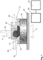
- a device for evaluating a noise behavior of a fluid 70 is shown schematically.
- the device comprises a base body 20 which is fastened on a platform 40.
- the base body 20 is shown in section.
- the device also comprises a counter body 10 which can be moved relative to a base body 20.
- a sufficient quantity of the fluid 70 to be assessed is located in a space between the base body 20 and the counter body 10.
- the fluid is a brake fluid.
- the platform 40 can be temperature controlled in order to simulate practical applications at higher or lower temperatures.
- the base body 20 is made of a metal and has approximately the shape of a circular disk. On a side facing away from the platform 40, the base body 20 has a flat surface 22. In the present case, the flat surface 22 is surrounded by a circumferential elevation 24. The elevation 24, together with the flat surface 22, forms a trough-like depression in the base body 20, which is used to receive the fluid 70 to be assessed. The elevation 24 of the base body 20 can also be omitted, in particular if droplet wetting of the flat surface 22 with the fluid 70 to be assessed is sufficient.
- the counter body 10 is made of an elastomer and designed as a piece from a cord material.
- the counter body 10 is designed to be circular-cylindrical and has a central axis 12.
- the central axis 12 of the counter body 10 runs parallel to the flat surface 22 of the base body 20.
- the counter body 10 protrudes into the tub-like Recess of the base body 20 and is in contact with the fluid 70 located there.
- the counter body 10 is firmly clamped in a holder 30.
- the holder 30 prevents the counter body 10 from rotating about its central axis 12.
- a coupling strut 50 is attached to the holder 30.
- the coupling strut 50 is a cylindrical rod and protrudes away from the holder 30 on a side facing away from the base body 20.
- the coupling strut 50 is used to apply a normal force N to the counter body 10.
- the normal force N is directed towards the base body 20 and is at right angles on the flat surface 22 of the base body 20.
- the normal force N is thus perpendicular to the central axis 12 of the counter body 10 .
- a force measuring system measures the normal force N and allows feedback for a control loop.
- the normal force N can be reproduced and tracked.
- the tracking is necessary in particular in the case of relaxing elastomer materials of the counter body 10.
- the holder 30 is also connected to a drive system 60.
- the drive system 60 comprises two cylindrical rods which are each connected to the holder 30 by means of a coupling (not shown here).
- the drive system 60 enables the holder 30 to be moved in a direction perpendicular to the central axis 12 of the counter body 10 and parallel to the flat surface 22 of the base body 20.
- the counter body 10 is also perpendicular to its central axis M and parallel to the flat surface 22 of the Base body 20 movable.
- the drive system 60 also includes an electrodynamic voice coil, not shown here, and in particular enables a translatory oscillating movement of the counter body 10 relative to the base body 20.
- An eccentric drive and a crank drive are also conceivable.
- the drive system 60 further comprises a position measuring system, not shown here, by means of which a positioning P of the counter body 10 relative to the base body 20 can be recorded. In the present case, the drive system 60 executes a stroke of 3 mm at a frequency of 2 Hz.
- the platform 40 includes sensors, not shown here, for measuring the frictional force RK.
- the sensors for measuring the frictional force RK are connected to a recording unit 80.
- the receiving unit 80 is also with the Distance measuring system of the drive system 60 and connected to the force measuring system for the normal force N.
- Measured values of the frictional force RK, measured values of the positioning P and measured values of the normal force N are transmitted to the recording unit 60 in a time-synchronous manner.
- the measured values of the frictional force RK are direction-dependent and, depending on the direction of the frictional force RK, positive or negative.
- the recording unit 80 serves to record the frictional force RK and / or the coefficient of friction RW between the counter body 10 and the base body 20 as a function of the positioning P of the counter body 10 relative to the base body 20.
- the recording unit 80 in particular takes synchronous measured values of the friction force RK, the Normal force N and the positioning P.
- the recording unit 80 is connected to a computing unit 82.
- the computing unit 82 is used to determine a friction force fluctuation RKS from the friction force RK and to determine a friction coefficient fluctuation RWS from the friction coefficient RW. Furthermore, the computing unit 82 serves to calculate a fluctuation mean value SM from the friction force fluctuation RKS and from the friction value fluctuation RWS.
- the counter body 10 When carrying out the method, the counter body 10 is moved relative to the base body, while the fluid 70 is located between the counter body 10 and the base body 20.
- the counter body is moved in a translatory oscillating manner at right angles to its central axis 12 and parallel to the flat surface 22 of the base body 20, with its central axis 12 running parallel to the flat surface 22.
- a normal force N is applied to the counter body 10, which is directed in the direction of the base body 20 and is at right angles on the flat surface 22.
- a frictional force RK between the counter body 10 and the base body 20 is recorded synchronously as a function of the positioning P of the counter body 10 relative to the base body 20.
- the frictional force RK between the counter body 10 and the base body 20 is presently recorded during a complete cycle of the oscillating movement.
- the coefficient of friction RW is calculated as a quotient from the frictional force RK and the normal force N. With a constant normal force N, the coefficient of friction RW is directly proportional to the friction force RK.
- Figure 2 shows a graphic representation of the coefficient of friction RK of the fluid 70 as a function of the positioning P during a complete cycle. Depending on the direction of the frictional force RK, the coefficient of friction RW is plotted positively or negatively.
- an upper envelope OE and a lower envelope UE are calculated for the coefficient of friction RW.
- Figure 3 shows a graphic representation of the coefficient of friction RK from Figure 2 with the upper envelope OE and the lower envelope UE.
- an upper envelope OE and a lower envelope UE can also be calculated for the frictional force RK.
- a friction coefficient fluctuation RWS is then determined from a difference between the upper envelope OE and the lower envelope UE of the coefficient of friction RW.
- Figure 4 shows a graphic representation of the coefficient of friction fluctuation RW as the difference between that of the upper envelope OE and the lower envelope UE Figure 3 .
- a friction force fluctuation RKS can also be determined from a difference between the upper envelope OE and the lower envelope UE of the frictional force RK.
- a mean fluctuation value (SM) is then calculated from the fluctuation in the coefficient of friction RWS and / or from the fluctuation in the friction force RKS.
- the fluctuation mean value SM calculated from the fluctuation in the coefficient of friction RWS is in Figure 4 also shown.
- the fluctuation mean value SM calculated according to the first variant for the fluid 70 has a numerical value of approximately 0.07 in the present case.
- a sliding mean value GM is calculated for the coefficient of friction RW.
- Figure 5 shows a graphic representation of the coefficient of friction RK from Figure 2 with moving average GM.
- a sliding mean value GM for the frictional force RK can also be calculated.
- a friction coefficient fluctuation RWS is then determined from a distance between the coefficient of friction RW and the sliding mean value GM.
- Figure 6 shows a graphic representation of the coefficient of friction fluctuation RW as a distance from the moving average value GM Figure 5 .
- a friction force fluctuation RKS can also be determined from a distance between the frictional force RK and the sliding mean value GM.
- a mean fluctuation value SM is then calculated from the fluctuation in the coefficient of friction RWS and / or from the fluctuation in the friction force RKS.
- the fluctuation mean value SM calculated from the fluctuation in the coefficient of friction RWS is in Figure 6 also shown.
- the fluctuation mean value SM calculated according to the second variant for the fluid 70 has a numerical value of approximately 0.03 in the present case.
- the frictional force RK can also be absorbed during several cycles of the oscillating movement.
- a temporary average fluctuation value SM is calculated for each cycle, and an overall average fluctuation value SM is calculated from the temporary average fluctuation values SM, in particular by averaging.
- Figure 7 shows a graphic representation of the coefficient of friction RK of another fluid 70 as a function of the positioning P during a complete cycle. From a visual comparison between Figure 2 and Figure 7 it can already be seen that the other fluid 70 has a lower mean fluctuation value SM.
- An acoustic sound recording can be carried out parallel to the recording of the frictional force RK, the determination of the friction coefficient fluctuation RWS and the calculation of the fluctuation mean value SM. It is found that the acoustic sound recording of the noise behavior of the fluid 70 correlates with the calculated mean fluctuation value SM.
- the calculated mean fluctuation value SM is therefore a measure of an amplitude of the noise generated by the fluid 70. The greater the mean fluctuation value SM, the higher the volume of this noise.
Landscapes
- Engineering & Computer Science (AREA)
- Transportation (AREA)
- Mechanical Engineering (AREA)
- Automation & Control Theory (AREA)
- Physics & Mathematics (AREA)
- Health & Medical Sciences (AREA)
- Life Sciences & Earth Sciences (AREA)
- Chemical & Material Sciences (AREA)
- Analytical Chemistry (AREA)
- Biochemistry (AREA)
- General Health & Medical Sciences (AREA)
- General Physics & Mathematics (AREA)
- Immunology (AREA)
- Pathology (AREA)
- Regulating Braking Force (AREA)
- Braking Arrangements (AREA)
Claims (14)
- Procédé d'évaluation du comportement acoustique d'un fluide (70), un corps antagoniste (10) étant déplacé par rapport à un corps de base (20) alors que le fluide (70) se trouve entre le corps antagoniste (10) et le corps de base (20) ; et pendant le mouvement, une force de frottement (RK) et/ou un coefficient de frottement (RW) entre le corps antagoniste (10) et le corps de base (20) étant enregistré en fonction d'un positionnement (P) du corps antagoniste (10) par rapport au corps de base (20) ; caractérisé en ce qu'une fluctuation (RKS) de la force de frottement est déterminée à partir de la force de frottement (RK) et/ou une fluctuation (RWS) du coefficient de frottement est déterminée à partir du coefficient de frottement (RW) ; et une valeur de fluctuation moyenne (SM) est calculée à partir de la fluctuation (RKS) de la force de frottement et/ou à partir de la fluctuation (RWS) du coefficient de frottement.
- Procédé selon la revendication 1, pendant le mouvement du corps antagoniste (10) par rapport au corps de base (20), une force normale (N), qui est dirigée vers le corps de base (20), étant appliquée sur le corps antagoniste (10).
- Procédé selon la revendication 2, le coefficient de frottement (RW) étant calculé à partir de la force de frottement (RK) et de la force normale (N).
- Procédé selon l'une des revendications précédentes, le corps antagoniste (10) étant déplacé de manière oscillante par rapport au corps de base (20).
- Procédé selon la revendication 4, la force de frottement (RK) et/ou le coefficient de frottement (RW) entre le corps antagoniste (10) et le corps de base (20) étant enregistrées pendant un cycle complet du mouvement oscillant.
- Procédé selon la revendication 4, la force de frottement (RK) et/ou le coefficient de frottement (RW) entre le corps antagoniste (10) et le corps de base (20) étant enregistrées pendant plusieurs cycles du mouvement oscillant.
- Procédé selon l'une des revendications précédentes, une enveloppe supérieure (OE) et une enveloppe inférieure (UE) étant calculées pour la force de frottement (RK) et/ou le coefficient de frottement (RW), et la fluctuation (RKS) de la force de frottement et/ou la fluctuation (RWS) du coefficient de frottement étant déterminées à partir d'une différence entre l'enveloppe supérieure (OE) et l'enveloppe inférieure (UE) .
- Procédé selon l'une des revendications 1 à 6, une valeur moyenne glissante (GM) étant calculée pour la force de frottement (RK) et/ou le coefficient de frottement (RW), et la fluctuation (RKS) de la force de frottement et/ou la fluctuation (RWS) du coefficient de frottement étant déterminées à partir d'une distance de la force de frottement (RK) et/ou du coefficient de frottement (RW) à la valeur moyenne glissante (GM).
- Procédé selon l'une des revendications précédentes, le corps antagoniste (10) étant conçu comme un cylindrique à base circulaire et comportant un axe central (12), et le corps de base (20) comportant une surface plane (22), le corps antagoniste (10) étant déplacé perpendiculairement à l'axe central (12) et parallèlement à la surface plane (22) du corps de base (20), l'axe central (12) étant parallèle à la surface plane (22).
- Procédé selon l'une des revendications précédentes, un enregistrement sonore étant en outre effectué pendant le mouvement du corps antagoniste (10) par rapport au corps de base (20).
- Procédé selon l'une des revendications précédentes d'évaluation du comportement acoustique d'un liquide de frein.
- Dispositif d'évaluation du comportement acoustique d'un fluide (70), ledit dispositif comprenant un corps antagoniste (10) qui est mobile par rapport à un corps de base (20), alors que le fluide (70) se trouve entre le corps antagoniste (10) et le corps de base (20) ; un système d'entraînement (60) destiné à déplacer le corps antagoniste (10) par rapport au corps de base (20) ; et une unité d'enregistrement (80) destinée à enregistrer une force de frottement (RK) et/ou un coefficient de frottement (RW) entre le corps antagoniste (10) et le corps de base (20) en fonction d'un positionnement (P) du corps antagoniste (10) par rapport au corps de base (20), caractérisé en ce que le dispositif comporte une unité de calcul (82) destiné à déterminer une fluctuation (RKS) de la force de frottement à partir de la force de frottement (RK) et/ou une fluctuation (RWS) du coefficient de frottement à partir du coefficient de frottement (RW), et à calculer une valeur de fluctuation moyenne (SM) à partir de la fluctuation (RKS) de la force de frottement et/ou à partir de la fluctuation (RWS) du coefficient de frottement.
- Dispositif selon la revendication 12, le corps antagoniste (10) étant conçu comme un cylindre à base circulaire et comportant un axe central (12), et le corps de base (20) ayant une surface plane (22), le corps antagoniste (10) pouvant être déplacé perpendiculairement à l'axe central (M) et parallèlement à la surface plane (22) du corps de base (20), l'axe central (12) étant parallèle à la surface plane (22).
- Dispositif selon l'une des revendications 12 à 13, le corps antagoniste étant fabriqué à partir d'un élastomère et le corps de base étant fabriqué à partir d'un métal.
Priority Applications (1)
| Application Number | Priority Date | Filing Date | Title |
|---|---|---|---|
| EP17154522.1A EP3358336B1 (fr) | 2017-02-03 | 2017-02-03 | Procédé et dispositif d'évaluation des caractéristiques sonores d'un fluide |
Applications Claiming Priority (1)
| Application Number | Priority Date | Filing Date | Title |
|---|---|---|---|
| EP17154522.1A EP3358336B1 (fr) | 2017-02-03 | 2017-02-03 | Procédé et dispositif d'évaluation des caractéristiques sonores d'un fluide |
Publications (2)
| Publication Number | Publication Date |
|---|---|
| EP3358336A1 EP3358336A1 (fr) | 2018-08-08 |
| EP3358336B1 true EP3358336B1 (fr) | 2021-10-13 |
Family
ID=58056962
Family Applications (1)
| Application Number | Title | Priority Date | Filing Date |
|---|---|---|---|
| EP17154522.1A Not-in-force EP3358336B1 (fr) | 2017-02-03 | 2017-02-03 | Procédé et dispositif d'évaluation des caractéristiques sonores d'un fluide |
Country Status (1)
| Country | Link |
|---|---|
| EP (1) | EP3358336B1 (fr) |
Families Citing this family (1)
| Publication number | Priority date | Publication date | Assignee | Title |
|---|---|---|---|---|
| EP4582524A1 (fr) | 2024-01-03 | 2025-07-09 | Clariant International Ltd | Fluide fonctionnel |
Family Cites Families (7)
| Publication number | Priority date | Publication date | Assignee | Title |
|---|---|---|---|---|
| JPS59206740A (ja) * | 1983-05-10 | 1984-11-22 | Hino Motors Ltd | ピストンの摩擦力測定装置 |
| US5679883A (en) * | 1992-10-19 | 1997-10-21 | Wedeven; Lavern D. | Method and apparatus for comprehensive evaluation of tribological materials |
| ATE237128T1 (de) * | 2000-03-07 | 2003-04-15 | Sulzer Markets & Technology Ag | Verfahren und anordnung zur beurteilung des reibverhaltens zwischen zwei gegenlaufpartnern |
| US6752001B1 (en) * | 2002-11-07 | 2004-06-22 | Lapointe Lou | Lubricant tester |
| CA2689685C (fr) * | 2007-06-05 | 2016-05-17 | Cargill, Incorporated | Procedes d'estimation d'attributs de saveur d'aliments a l'aide d'un dispositif de tribologie |
| DE102008063891A1 (de) | 2008-12-19 | 2010-07-01 | Knorr-Bremse Systeme für Schienenfahrzeuge GmbH | Bremsanlage eines Schienenfahrzeugs reduziertem Stick-Slip-Effekt |
| WO2014179537A1 (fr) * | 2013-05-03 | 2014-11-06 | Shell Oil Company | Procédés de test de friction de lubrifiants |
-
2017
- 2017-02-03 EP EP17154522.1A patent/EP3358336B1/fr not_active Not-in-force
Also Published As
| Publication number | Publication date |
|---|---|
| EP3358336A1 (fr) | 2018-08-08 |
Similar Documents
| Publication | Publication Date | Title |
|---|---|---|
| Skåre et al. | Wear and frictional behaviour of high strength steel in stamping monitored by acoustic emission technique | |
| WO2013156068A1 (fr) | Procédé et dispositif de mesure pour contrôler des états de fonctionnement d'un palier lisse | |
| EP4003646A1 (fr) | Outil d'usinage par écoulement abrasif pour déterminer un retrait de matériau d'une pièce à usiner et procédé pour déterminer la puissance de coupe d'un milieu abrasif | |
| EP1703268A1 (fr) | Procédé et dispositif destiné à la vérification de l'adhérence de couches de glissement de coussinets lisses | |
| EP3358336B1 (fr) | Procédé et dispositif d'évaluation des caractéristiques sonores d'un fluide | |
| DE102007007405A1 (de) | Elektrische Einrichtung zur Erkennung des Verschleißzustandes eines dynamischen Dichtelementes | |
| DE112009000454T5 (de) | Vorrichtung zum Messen des Einflusses der Reibkraft auf die Verschleißeigenschaften einer Materialoberfläche | |
| DE102004063358A1 (de) | Verfahren zur Bestimmung der Viskosität und Viskosimeter | |
| DE102006021937A1 (de) | Verfahren zur Bestimmung des Verschleißzustands eines Schwingungsdämpfers | |
| DE102017212666A1 (de) | Vorrichtung zur Bestimmung des Zustands eines mechanischen Bauteils, Verwendung eines Messgeräts, System, Verfahren zur Bestimmung des Zustands eines mechanischen Bauteils | |
| DE112020005447T5 (de) | Nabenlager | |
| EP2378146A2 (fr) | Procédé de surveillance d'un guidage linéaire | |
| DE102004038801B4 (de) | Verfahren und Vorrichtung zur Erkennung von Gaseinschlüssen in einem zähflüssigen Medium | |
| DE102018100911A1 (de) | Verfahren zur Früherkennung von Schäden an einer Werkzeugmaschine; Vorrichtung zum Durchführen des Verfahrens; sowie Werkzeugmaschine | |
| DE102007048182B3 (de) | Messanordnung und Verfahren zur Erfassung eines Ölzustandes von Motorölen im laufenden Betrieb eines Motors | |
| DE102014222386A1 (de) | Diagnose- und Prüfungsverfahren von Krafteinleitungspunkten an Faserverbundbauteilen | |
| DE3933973A1 (de) | Verfahren und messeinrichtung fuer die messung der schmierfaehigkeit von schmiermitteln, insbesondere fuer kraftfahrzeuge, und der viskositaet von fluessigkeiten | |
| DE102008012811A1 (de) | Probenhalter, Vorrichtung und Verfahren zur außermotorischen Verschleißprüfung von Kolbenschaftbeschichtungen | |
| DE102013108840A1 (de) | Vorrichtung und Verfahren zur tribologischen Prüfung eines Prüfkörpers | |
| EP2100124A1 (fr) | Procédé de contrôle par impulsion à haute pression d'éléments mécaniques | |
| DE1932736C3 (de) | Schmiersystem | |
| DE102016201642A1 (de) | Vorrichtung, Verfahren und deren Verwendung zur Verschleißmessung und Maschinenanordnung | |
| DE102014204543B4 (de) | Verfahren und Vorrichtung zur Bestimmung des reinen Schmiermittelanteils eines aus einer Lageranordnung entnommenen Schmiermittels | |
| DE102012202741B4 (de) | Verfahren zum Ermitteln wenigstens einer Spannungs-Dehnungs-Beziehung mittels eines Prüfkörpers | |
| DE3310508A1 (de) | Hydraulikzylinder-kolben-einheit mit aenderbarem wirkdurchmesser fuer schwingfestigkeits-untersuchung von probestuecken |
Legal Events
| Date | Code | Title | Description |
|---|---|---|---|
| PUAI | Public reference made under article 153(3) epc to a published international application that has entered the european phase |
Free format text: ORIGINAL CODE: 0009012 |
|
| STAA | Information on the status of an ep patent application or granted ep patent |
Free format text: STATUS: THE APPLICATION HAS BEEN PUBLISHED |
|
| AK | Designated contracting states |
Kind code of ref document: A1 Designated state(s): AL AT BE BG CH CY CZ DE DK EE ES FI FR GB GR HR HU IE IS IT LI LT LU LV MC MK MT NL NO PL PT RO RS SE SI SK SM TR |
|
| AX | Request for extension of the european patent |
Extension state: BA ME |
|
| STAA | Information on the status of an ep patent application or granted ep patent |
Free format text: STATUS: REQUEST FOR EXAMINATION WAS MADE |
|
| 17P | Request for examination filed |
Effective date: 20180824 |
|
| RBV | Designated contracting states (corrected) |
Designated state(s): AL AT BE BG CH CY CZ DE DK EE ES FI FR GB GR HR HU IE IS IT LI LT LU LV MC MK MT NL NO PL PT RO RS SE SI SK SM TR |
|
| GRAP | Despatch of communication of intention to grant a patent |
Free format text: ORIGINAL CODE: EPIDOSNIGR1 |
|
| STAA | Information on the status of an ep patent application or granted ep patent |
Free format text: STATUS: GRANT OF PATENT IS INTENDED |
|
| RIN1 | Information on inventor provided before grant (corrected) |
Inventor name: MOGCK, OLIVER Inventor name: HARDER, JOHANNES Inventor name: WEIDE, TIMO Inventor name: GREBE, MARKUS Inventor name: BUSE, HENDRIK |
|
| RIC1 | Information provided on ipc code assigned before grant |
Ipc: G01N 19/02 20060101AFI20210614BHEP Ipc: B60T 17/22 20060101ALI20210614BHEP |
|
| INTG | Intention to grant announced |
Effective date: 20210630 |
|
| GRAS | Grant fee paid |
Free format text: ORIGINAL CODE: EPIDOSNIGR3 |
|
| GRAA | (expected) grant |
Free format text: ORIGINAL CODE: 0009210 |
|
| STAA | Information on the status of an ep patent application or granted ep patent |
Free format text: STATUS: THE PATENT HAS BEEN GRANTED |
|
| AK | Designated contracting states |
Kind code of ref document: B1 Designated state(s): AL AT BE BG CH CY CZ DE DK EE ES FI FR GB GR HR HU IE IS IT LI LT LU LV MC MK MT NL NO PL PT RO RS SE SI SK SM TR |
|
| REG | Reference to a national code |
Ref country code: GB Ref legal event code: FG4D Free format text: NOT ENGLISH |
|
| REG | Reference to a national code |
Ref country code: CH Ref legal event code: EP |
|
| REG | Reference to a national code |
Ref country code: DE Ref legal event code: R096 Ref document number: 502017011695 Country of ref document: DE |
|
| REG | Reference to a national code |
Ref country code: IE Ref legal event code: FG4D Free format text: LANGUAGE OF EP DOCUMENT: GERMAN |
|
| REG | Reference to a national code |
Ref country code: AT Ref legal event code: REF Ref document number: 1438518 Country of ref document: AT Kind code of ref document: T Effective date: 20211115 |
|
| REG | Reference to a national code |
Ref country code: LT Ref legal event code: MG9D |
|
| REG | Reference to a national code |
Ref country code: NL Ref legal event code: MP Effective date: 20211013 |
|
| PG25 | Lapsed in a contracting state [announced via postgrant information from national office to epo] |
Ref country code: RS Free format text: LAPSE BECAUSE OF FAILURE TO SUBMIT A TRANSLATION OF THE DESCRIPTION OR TO PAY THE FEE WITHIN THE PRESCRIBED TIME-LIMIT Effective date: 20211013 Ref country code: LT Free format text: LAPSE BECAUSE OF FAILURE TO SUBMIT A TRANSLATION OF THE DESCRIPTION OR TO PAY THE FEE WITHIN THE PRESCRIBED TIME-LIMIT Effective date: 20211013 Ref country code: FI Free format text: LAPSE BECAUSE OF FAILURE TO SUBMIT A TRANSLATION OF THE DESCRIPTION OR TO PAY THE FEE WITHIN THE PRESCRIBED TIME-LIMIT Effective date: 20211013 Ref country code: BG Free format text: LAPSE BECAUSE OF FAILURE TO SUBMIT A TRANSLATION OF THE DESCRIPTION OR TO PAY THE FEE WITHIN THE PRESCRIBED TIME-LIMIT Effective date: 20220113 |
|
| PG25 | Lapsed in a contracting state [announced via postgrant information from national office to epo] |
Ref country code: IS Free format text: LAPSE BECAUSE OF FAILURE TO SUBMIT A TRANSLATION OF THE DESCRIPTION OR TO PAY THE FEE WITHIN THE PRESCRIBED TIME-LIMIT Effective date: 20220213 Ref country code: SE Free format text: LAPSE BECAUSE OF FAILURE TO SUBMIT A TRANSLATION OF THE DESCRIPTION OR TO PAY THE FEE WITHIN THE PRESCRIBED TIME-LIMIT Effective date: 20211013 Ref country code: PT Free format text: LAPSE BECAUSE OF FAILURE TO SUBMIT A TRANSLATION OF THE DESCRIPTION OR TO PAY THE FEE WITHIN THE PRESCRIBED TIME-LIMIT Effective date: 20220214 Ref country code: PL Free format text: LAPSE BECAUSE OF FAILURE TO SUBMIT A TRANSLATION OF THE DESCRIPTION OR TO PAY THE FEE WITHIN THE PRESCRIBED TIME-LIMIT Effective date: 20211013 Ref country code: NO Free format text: LAPSE BECAUSE OF FAILURE TO SUBMIT A TRANSLATION OF THE DESCRIPTION OR TO PAY THE FEE WITHIN THE PRESCRIBED TIME-LIMIT Effective date: 20220113 Ref country code: NL Free format text: LAPSE BECAUSE OF FAILURE TO SUBMIT A TRANSLATION OF THE DESCRIPTION OR TO PAY THE FEE WITHIN THE PRESCRIBED TIME-LIMIT Effective date: 20211013 Ref country code: LV Free format text: LAPSE BECAUSE OF FAILURE TO SUBMIT A TRANSLATION OF THE DESCRIPTION OR TO PAY THE FEE WITHIN THE PRESCRIBED TIME-LIMIT Effective date: 20211013 Ref country code: HR Free format text: LAPSE BECAUSE OF FAILURE TO SUBMIT A TRANSLATION OF THE DESCRIPTION OR TO PAY THE FEE WITHIN THE PRESCRIBED TIME-LIMIT Effective date: 20211013 Ref country code: GR Free format text: LAPSE BECAUSE OF FAILURE TO SUBMIT A TRANSLATION OF THE DESCRIPTION OR TO PAY THE FEE WITHIN THE PRESCRIBED TIME-LIMIT Effective date: 20220114 Ref country code: ES Free format text: LAPSE BECAUSE OF FAILURE TO SUBMIT A TRANSLATION OF THE DESCRIPTION OR TO PAY THE FEE WITHIN THE PRESCRIBED TIME-LIMIT Effective date: 20211013 |
|
| REG | Reference to a national code |
Ref country code: DE Ref legal event code: R097 Ref document number: 502017011695 Country of ref document: DE |
|
| PG25 | Lapsed in a contracting state [announced via postgrant information from national office to epo] |
Ref country code: SM Free format text: LAPSE BECAUSE OF FAILURE TO SUBMIT A TRANSLATION OF THE DESCRIPTION OR TO PAY THE FEE WITHIN THE PRESCRIBED TIME-LIMIT Effective date: 20211013 Ref country code: SK Free format text: LAPSE BECAUSE OF FAILURE TO SUBMIT A TRANSLATION OF THE DESCRIPTION OR TO PAY THE FEE WITHIN THE PRESCRIBED TIME-LIMIT Effective date: 20211013 Ref country code: RO Free format text: LAPSE BECAUSE OF FAILURE TO SUBMIT A TRANSLATION OF THE DESCRIPTION OR TO PAY THE FEE WITHIN THE PRESCRIBED TIME-LIMIT Effective date: 20211013 Ref country code: EE Free format text: LAPSE BECAUSE OF FAILURE TO SUBMIT A TRANSLATION OF THE DESCRIPTION OR TO PAY THE FEE WITHIN THE PRESCRIBED TIME-LIMIT Effective date: 20211013 Ref country code: DK Free format text: LAPSE BECAUSE OF FAILURE TO SUBMIT A TRANSLATION OF THE DESCRIPTION OR TO PAY THE FEE WITHIN THE PRESCRIBED TIME-LIMIT Effective date: 20211013 Ref country code: CZ Free format text: LAPSE BECAUSE OF FAILURE TO SUBMIT A TRANSLATION OF THE DESCRIPTION OR TO PAY THE FEE WITHIN THE PRESCRIBED TIME-LIMIT Effective date: 20211013 |
|
| PLBE | No opposition filed within time limit |
Free format text: ORIGINAL CODE: 0009261 |
|
| STAA | Information on the status of an ep patent application or granted ep patent |
Free format text: STATUS: NO OPPOSITION FILED WITHIN TIME LIMIT |
|
| REG | Reference to a national code |
Ref country code: DE Ref legal event code: R119 Ref document number: 502017011695 Country of ref document: DE |
|
| 26N | No opposition filed |
Effective date: 20220714 |
|
| PG25 | Lapsed in a contracting state [announced via postgrant information from national office to epo] |
Ref country code: MC Free format text: LAPSE BECAUSE OF FAILURE TO SUBMIT A TRANSLATION OF THE DESCRIPTION OR TO PAY THE FEE WITHIN THE PRESCRIBED TIME-LIMIT Effective date: 20211013 |
|
| REG | Reference to a national code |
Ref country code: CH Ref legal event code: PL |
|
| REG | Reference to a national code |
Ref country code: BE Ref legal event code: MM Effective date: 20220228 |
|
| GBPC | Gb: european patent ceased through non-payment of renewal fee |
Effective date: 20220203 |
|
| PG25 | Lapsed in a contracting state [announced via postgrant information from national office to epo] |
Ref country code: LU Free format text: LAPSE BECAUSE OF NON-PAYMENT OF DUE FEES Effective date: 20220203 Ref country code: AL Free format text: LAPSE BECAUSE OF FAILURE TO SUBMIT A TRANSLATION OF THE DESCRIPTION OR TO PAY THE FEE WITHIN THE PRESCRIBED TIME-LIMIT Effective date: 20211013 |
|
| PG25 | Lapsed in a contracting state [announced via postgrant information from national office to epo] |
Ref country code: SI Free format text: LAPSE BECAUSE OF FAILURE TO SUBMIT A TRANSLATION OF THE DESCRIPTION OR TO PAY THE FEE WITHIN THE PRESCRIBED TIME-LIMIT Effective date: 20211013 |
|
| PG25 | Lapsed in a contracting state [announced via postgrant information from national office to epo] |
Ref country code: FR Free format text: LAPSE BECAUSE OF NON-PAYMENT OF DUE FEES Effective date: 20220228 |
|
| PG25 | Lapsed in a contracting state [announced via postgrant information from national office to epo] |
Ref country code: LI Free format text: LAPSE BECAUSE OF NON-PAYMENT OF DUE FEES Effective date: 20220228 Ref country code: IE Free format text: LAPSE BECAUSE OF NON-PAYMENT OF DUE FEES Effective date: 20220203 Ref country code: GB Free format text: LAPSE BECAUSE OF NON-PAYMENT OF DUE FEES Effective date: 20220203 Ref country code: DE Free format text: LAPSE BECAUSE OF NON-PAYMENT OF DUE FEES Effective date: 20220901 Ref country code: CH Free format text: LAPSE BECAUSE OF NON-PAYMENT OF DUE FEES Effective date: 20220228 |
|
| PG25 | Lapsed in a contracting state [announced via postgrant information from national office to epo] |
Ref country code: BE Free format text: LAPSE BECAUSE OF NON-PAYMENT OF DUE FEES Effective date: 20220228 |
|
| REG | Reference to a national code |
Ref country code: AT Ref legal event code: MM01 Ref document number: 1438518 Country of ref document: AT Kind code of ref document: T Effective date: 20220203 |
|
| PG25 | Lapsed in a contracting state [announced via postgrant information from national office to epo] |
Ref country code: AT Free format text: LAPSE BECAUSE OF NON-PAYMENT OF DUE FEES Effective date: 20220203 |
|
| PG25 | Lapsed in a contracting state [announced via postgrant information from national office to epo] |
Ref country code: IT Free format text: LAPSE BECAUSE OF FAILURE TO SUBMIT A TRANSLATION OF THE DESCRIPTION OR TO PAY THE FEE WITHIN THE PRESCRIBED TIME-LIMIT Effective date: 20211013 |
|
| PG25 | Lapsed in a contracting state [announced via postgrant information from national office to epo] |
Ref country code: HU Free format text: LAPSE BECAUSE OF FAILURE TO SUBMIT A TRANSLATION OF THE DESCRIPTION OR TO PAY THE FEE WITHIN THE PRESCRIBED TIME-LIMIT; INVALID AB INITIO Effective date: 20170203 |
|
| PG25 | Lapsed in a contracting state [announced via postgrant information from national office to epo] |
Ref country code: MK Free format text: LAPSE BECAUSE OF FAILURE TO SUBMIT A TRANSLATION OF THE DESCRIPTION OR TO PAY THE FEE WITHIN THE PRESCRIBED TIME-LIMIT Effective date: 20211013 Ref country code: CY Free format text: LAPSE BECAUSE OF FAILURE TO SUBMIT A TRANSLATION OF THE DESCRIPTION OR TO PAY THE FEE WITHIN THE PRESCRIBED TIME-LIMIT Effective date: 20211013 |
|
| PG25 | Lapsed in a contracting state [announced via postgrant information from national office to epo] |
Ref country code: TR Free format text: LAPSE BECAUSE OF FAILURE TO SUBMIT A TRANSLATION OF THE DESCRIPTION OR TO PAY THE FEE WITHIN THE PRESCRIBED TIME-LIMIT Effective date: 20211013 |
|
| PG25 | Lapsed in a contracting state [announced via postgrant information from national office to epo] |
Ref country code: MT Free format text: LAPSE BECAUSE OF FAILURE TO SUBMIT A TRANSLATION OF THE DESCRIPTION OR TO PAY THE FEE WITHIN THE PRESCRIBED TIME-LIMIT Effective date: 20211013 |