EP3358538B1 - Vorrats- und abgabestation für einen blisterautomaten - Google Patents
Vorrats- und abgabestation für einen blisterautomaten Download PDFInfo
- Publication number
- EP3358538B1 EP3358538B1 EP17154512.2A EP17154512A EP3358538B1 EP 3358538 B1 EP3358538 B1 EP 3358538B1 EP 17154512 A EP17154512 A EP 17154512A EP 3358538 B1 EP3358538 B1 EP 3358538B1
- Authority
- EP
- European Patent Office
- Prior art keywords
- storage
- electrically conducting
- separating device
- packaging machine
- blister packaging
- Prior art date
- Legal status (The legal status is an assumption and is not a legal conclusion. Google has not performed a legal analysis and makes no representation as to the accuracy of the status listed.)
- Active
Links
Images


Classifications
-
- G—PHYSICS
- G07—CHECKING-DEVICES
- G07F—COIN-FREED OR LIKE APPARATUS
- G07F17/00—Coin-freed apparatus for hiring articles; Coin-freed facilities or services
- G07F17/0092—Coin-freed apparatus for hiring articles; Coin-freed facilities or services for assembling and dispensing of pharmaceutical articles
-
- G—PHYSICS
- G07—CHECKING-DEVICES
- G07F—COIN-FREED OR LIKE APPARATUS
- G07F11/00—Coin-freed apparatus for dispensing, or the like, discrete articles
- G07F11/02—Coin-freed apparatus for dispensing, or the like, discrete articles from non-movable magazines
- G07F11/44—Coin-freed apparatus for dispensing, or the like, discrete articles from non-movable magazines in which magazines the articles are stored in bulk
Definitions
- the present invention relates to a storage and delivery station for a blister dispenser for medicament portions.
- Modern blister machines such as those in the WO 2013/034504 A1 are disclosed include, depending on the expansion stage of the blister machine, several hundred storage and delivery stations. A plurality of medicament portions of a specific medicament is stored in each of these, and individual medicament portions can be dispensed on request. With the blister machines, the drug portions stored in the storage and dispensing stations are put together and blistered according to the times of administration prescribed by the doctor.
- appropriate storage and dispensing stations for dispensing one or more medicament portions are controlled by a control device of the blister machine.
- a medicament portion stored in a storage container is separated with a separating device of the storage and dispensing station and transferred via a dispensing opening to a guide device of the blister machine.
- the dispensed medicament portion is fed by means of the guide device, optionally with the interposition of a collecting device, to a packaging device which blisters individual or multiple medicament portions.
- the separating device arranged in a section of the storage container is usually in the form of a rotor which has a plurality of channels extending through the separating device in the axial direction. Above the separating device is a receiving space for the medicament portions to be separated.
- the separating device is rotated via a drive in order to separate medicinal product portions.
- the rotation of the separating device causes at least part of the drug portions stored in the storage container to also rotate, so that during the separating process they come into contact with one another as well as with the separating device and an inner wall of the storage container. This regularly results in tiny spalling off of the medicament portions and a type of medicament dust is produced which settles on the separating device and on the wall of the storage container.
- a non-generic type of dispensing device for medicament portions which, in contrast to the one described above, works with a horizontal screw conveyor which feeds the medicament portions to be dispensed to a dispensing opening.
- the storage and delivery station according to the invention for a blister machine comprises a base part, via which the storage and delivery station is usually attached to a blister machine, at least one contact means with which the storage - And delivery station can be electrically coupled to a blister machine and via which electrical charges can be discharged to the blister machine, one on the Base part arranged reservoir, which has a housing enclosing a receiving space for drug portions, which has a circular-cylindrical receiving space, a bottom surface and a separating device rotatably arranged in the circular-cylindrical receiving space with a plurality of channels extending in the axial direction through the separating device and a coupling means, as well as a Drive for moving the separation device.
- the separating device is electrically conductive at least on its outer surface that comes into contact with the medicament portions to be separated, and a line device is provided via which the electrically conductive outer surface of the separating device is electrically conductively coupled to the contact means.
- the line device comprises an electrically conductive drive hub, an electrically conductive drive shaft and a motor and the coupling means is electrically conductive, the electrically conductive outer surface of the separating device being electrically is conductively coupled to the coupling means and wherein the motor is coupled to the contact means.
- existing components are designed to be conductive in such a way that the electrical charge of the separating device can be dissipated via them.
- the motor of the drive of the storage and dispensing station is usually coupled to the central power supply of the blister machine via a line.
- the engine is also via the contact means with a blister machine connected, and this means of contact ensures that the motor is grounded. Charges that are transferred to the motor via the coupling means, the drive hub and finally the drive shaft can thus be discharged to the blister machine.
- the inventive design of the separating device and the provision of the line device designed according to the invention allows the electrostatic charge of the separating device to be dissipated via the contact means on the blister machine, which forms or has a reference potential for the separating device.
- the reduction of the electrostatic charge of the separation device means that the drug dust produced during separation no longer adheres to it, or only to a lesser extent. This facilitates cleaning of the separating device and avoids falling or swept away accumulations of medicament dust from the storage and dispensing station being carried to other parts of the blister machine.
- the separating device is arranged in the circular-cylindrical receiving space of the housing. Depending on the precise configuration of the receiving space and the separating device, this can be accommodated completely in the receiving space, but it is possible for an upper section of the separating device to protrude from the circular-cylindrical receiving space.
- a supply and dispensing station is electrically coupled to the blister machine by the contact means, specifically in such a way that electrical charges can be discharged from the blister machine.
- the dispensing and storage station is electrically coupled to a blister machine (via the contact means), the separating device is grounded.
- the contact means can be arranged in the base part or the reservoir, which can be designed as a common component or as separate, connectable components.
- the base part and the storage container are designed as separate but connectable components, with the storage container being able to be plugged onto the base part.
- the base part can simply be removed from the base part loosened and then cleaned and/or refilled and put back on.
- the base part is detachably connected to the blister machine, with electrical contacts between the blister machine and base part, for example a power supply for a drive and/or a line for a control unit of the storage and delivery station, being designed as plug connectors.
- a preferred embodiment of the storage and delivery station provides that the contact means is provided or designed as such, at least in sections, by means of a ground line which is coupled to a motor of the drive.
- a component or component group that is present anyway namely the grounding of the motor of the drive, is also used to discharge electrical charges.
- the separating device is electrically conductive at least on the outer surface that comes into contact with the medicament portions to be separated.
- the electrically conductive outer surface of the separating device is designed as a conductive coating over a large area.
- An inexpensive, non-conductive material can be used as the carrier material, and the more expensive conductive coating can only be provided in the areas that come into contact with the medicament portions to be separated, which is then electrically conductively coupled to the contact means via the line device.
- an electrically conductive coating is to be applied to a base body.
- the separating device at least in its electrically conductive outer surface consists of an electrically conductive material, preferably an electrically conductive plastic. This conductive area is then again coupled to the contact means.
- the separating device it can also be advantageous for the separating device to consist entirely of a conductive material.
- the medicament dust settles mainly on or on it.
- the electrostatic charge also causes the medicament portions to adhere to a certain extent on the separating device, so that it is more difficult for medicament portions to penetrate into the channels.
- other components of the storage and dispensing station also become electrostatically charged, so that in a preferred embodiment it is provided that surfaces of the base surface, the circular-cylindrical section of the housing and/or other sections that come into contact with medicament portions of the housing are electrically conductive and are electrically coupled to the contact means.
- surfaces of the base surface, the circular-cylindrical section of the housing and/or other sections that come into contact with medicament portions of the housing are electrically conductive and are electrically coupled to the contact means.
- the coupling to the contact means, via which the electrical charges are finally discharged to the blister machine can be established using any means known to those skilled in the art.
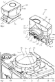
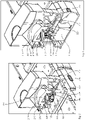
- FIGS 1a and 1b show oblique views of a storage and delivery station, with the following figures showing details of the storage and delivery station, which serves as the basis for the invention.
- the storage and delivery station includes a base part 100 and a storage container 200, which are designed as separate components in the first embodiment.
- the base part 100 is part of a combination of five base parts 100. Alternatively, the base parts can be designed separately from one another. The components mentioned in the following description of the base part 100 are each present in each base part 100, regardless of whether they are composite (as in Figs Figures 1a and 1b ) or executed separately.
- Each base part 100 comprises a lower section 130 and an upper section 120.
- the upper section 120 comprises a projection 121 onto which a reservoir 200 can be slid.
- a lower housing section of the reservoir 200 is adapted to the geometry of the projection 121 .
- a chute 140 is formed, over which separated drug portions are transferred from a storage and delivery station to a guide device within the blister machine.
- the chute 140 extends through the base part 100 to the projection 121 in which an opening 123 for receiving a medicament portion is formed.
- a contact means 124 is provided on the aforementioned end face of the base part 100, with which the storage and dispensing station can be electrically coupled to the blister machine and via which electrical charges can be discharged from the blister machine.
- the contact means 124 is arranged in the end face section of the upper section of the base part 100 , alternatively the contact means 124 can also be arranged in the end face section of the lower section 130 .
- the contact means can be designed, for example, as a plug or the like.
- a contact element 122 is arranged in the projection, which is electrically coupled to the contact means 124 on the one hand and to the electrically conductive outer surface of a separating device (not shown here) on the other hand.
- the contact element is part of the line device.
- the contact element is dependent on the precise configuration of the line device of the first embodiment.
- the line device can also be provided in such a way that the use of a contact element designed as a separate component is superfluous (see the embodiments described further below).
- the position is not limited to the illustrated one, the contact element can also be formed outside the projection.
- FIG 2 shows an oblique view of the storage container of the storage and delivery station.
- the base part 100 and the storage container 200 are designed as separate components of the storage and delivery station.
- the reservoir 200 includes a housing 210 having a one (in figure 3 illustrated) circular-cylindrical receiving space 211 comprehensive portion 217 (receiving space portion), a lower portion 212 and a grip element 214.
- the reservoir 200 also includes a lid 213, which can be removed, among other things, to refill drug portions.
- figure 3 shows a sectional view of the reservoir.
- the arrangement of a separating device 230 in the receiving space 211 of the receiving section 217 of the housing 210 can be seen from this sectional view.
- the separating device 230 is designed as a type of rotor with a plurality of projections 234 and channels 235 which extend through the separating device 230 in the axial direction.
- the channels 235 are defined by the protrusions 234 on a central component of the singulator 230 such that the channels are open to the outer periphery of the singulator.
- the separating device 230 comprises a central conical cover surface 232 which, together with the housing 210, defines a receiving space 202 for medicament portions. Due to the conical design of the top surface, portions of medication lying on it slide towards the channels 235.
- a step is formed between the conical top surface 232 and the projections 234, so that a type of annular space is formed in the area above the channels and the projections.
- a corresponding annular space can promote the supply of medicament portions into the channels.
- the bottom surface 220 has a dispensing opening 221, through which separated portions of medication can be dispensed through an opening 123 in the projection 121 of the base part 100 (see Figure 1a ) of the chute 140 are fed.
- a retaining section 216 of a retaining means 215 is introduced into the annular space above the discharge opening 221 .
- an opening is provided in the circular-cylindrical section 211 of the housing 210 .
- the function of the retaining means, and particularly the retaining portion, is to retain portions of medicament located in the receiving space 202 over the dispensing port when a channel 235 is aligned with the dispensing port 221 .
- a separation or dispensing of medicament portions takes place in that a channel containing a defined number of medicament portions is moved over the dispensing opening 221 so that the defined number of medicament portions can be dispensed from the aligned channel.
- the retention section 216 prevents overlying medicament portions from also being dispensed, so that it is ensured that only the number of medicament portions arranged in a channel is dispensed.
- the separating device 230 also includes a coupling means 240, with which the separating device 230 can be coupled to a drive, via which the separating device can be rotated for the purpose of separating medicament portions.
- the coupling means is designed as a separate component, but alternatively it can also be provided that the coupling means is an integral part of the separating device 230 .
- the separating device is electrically conductive at least on its outer surface that comes into contact with the medicament portions to be separated. It can be provided that the separation device has a conductive coating 231 over the entire area.
- a line device is provided according to the invention.
- the line device can include a contact element 236, 237 arranged in the separating device 230, such an embodiment not being in accordance with the invention.
- the separating device 230 in figure 3 is accommodated in the accommodation space 211 almost entirely.
- the projections 245 end below the opening of the receiving space 211, so that a kind of annular space is created above it.
- the receiving space (or the separating device) can also be designed in such a way that the projections exceed the upper opening of the receiving space.
- drug portions can (also) enter the channels from the side.
- the precise configuration of the receiving space and the separating device depends on the medicament portions to be separated.
- FIG 4 two variants of the arrangement of the contact element are shown; once the contact element is arranged at the outer area of a projection 234 and once in the bottom surface of a projection 234 .
- an electrical coupling is established with a slip ring 222, 215, which is not according to the invention and is arranged in the bottom surface 220 and/or the receiving section 217.
- the arrangement of the aforementioned slip rings in the bottom surface 220 and the receiving portion 217 is in the Figures 5 and 6 illustrated.
- figure 5 shows a further sectional view of a storage container placed on a base part.
- figure 6 shows a sectional view of the complete storage and delivery station.
- Figures 5 and 6 illustrate in particular the coupling between the base part 100 and reservoir 200, which are designed as separate components Lower section 212 pushed onto the projection 121 of the base part 100, for which purpose the lower section 212 is adapted accordingly.
- figure 6 also illustrates the coupling between the separating device 230 and a drive arranged in the base part.
- the drive comprises a motor 112, a drive shaft 111 and a drive hub 110.
- An outer contour of the drive hub 110 interacts in a non-positive manner with an inner contour of the coupling means 240, which in turn interacts with the separating device itself via a corresponding connection.
- the coupling means 240 can be an integral part of the separating device 230 .
- the separating device 230 is at the Figures 5 and 6 shown in a dispensing position.
- a channel is aligned with the dispensing opening 221 in the bottom surface 220, drug portions arranged in the channel fall through the dispensing opening 221 into the chute 140 and from there get into the interior of the blister machine.
- the retaining section 216 of the retaining element 215 is introduced into the annular space above the channel aligned with the dispensing opening 221 and ensures that no further portions of medicament slip out of the receiving space.
- figure 7 shows an exploded view of the transition between the separating device 230 and the drive in an embodiment of the storage and delivery station according to the invention.
- the outer contour of the drive hub 110 can be seen in an opening in the projection 121 of the upper section of the base part.
- the coupling means 240 can be seen above this and the separating device 230 above this.
- figure 8 shows a sectional view through the embodiment, with a large part of the storage container being left out, in order in particular to show the coupling between the separating device and the drive.
- An electric motor 112 is arranged centrally in the base part 100 and is connected to the contact means 124 via a line 113 .
- the contact means serves, among other things, as a power supply for the electric motor 112.
- further components inside the base part or the reservoir can be connected to a control device (not shown) via the contact means.
- a sensor (not shown) can be associated with the chute 140 or the dispensing opening in the base of the storage container, which sensor determines whether a medicament portion is actually dispensed during a separating process.
- the electric motor 112 includes a drive shaft 111 which ends in a drive hub 110 .
- the drive hub 110 has an outer contour (see figure 7 ), which interacts with an inner contour 241 of the coupling means 240 in a form-fitting and detachable manner.
- the coupling means 240 is (detachably) connected to the separating device.
- connection between the drive hub 110 and the coupling means 240 of the separating device ensures that the storage container can be easily lifted off the base part without any further work steps.
- the coupling means is formed separately in relation to the separating device 230, but a connection between the coupling means 240 and the separating device remains when it is lifted off.
- a line device to be provided, via which the electrically conductive outer surface 231 of the separating device 230 is electrically conductively coupled to the contact means.
- the coupling means 240, the drive hub 110, the drive shaft 111 and the electric motor 110 represent components of the line device.
- the coupling means 240 is electrically conductive and conductively connected to the electrically conductive outer surface 231 of the isolating device 230 . This can be achieved, for example, by using a singulator is made entirely of a conductive material (e.g. an electrically conductive plastic). Alternatively, lines can be provided from the outer surface to the coupling means.
- the drive hub and the drive shaft are also electrically conductive, with regard to the precise embodiment stated above applies.
- the electrostatic charge that occurs during the separation or isolation can be dissipated via the outer surface of the isolation device to the coupling means, and from there to the drive hub and drive shaft.
- the charge can be discharged from the drive shaft via the motor and the line 113 to the contact means 124, via which the charge is finally discharged or can be discharged to the blister machine.
- the separating device and/or other components of the reservoir are earthed, as it were, via the blister machine.
Landscapes
- Physics & Mathematics (AREA)
- General Physics & Mathematics (AREA)
- Medical Preparation Storing Or Oral Administration Devices (AREA)
- Packages (AREA)
- Basic Packing Technique (AREA)
Description
- Die vorliegende Erfindung betrifft eine Vorrats- und Abgabestation für einen Blisterautomaten für Arzneimittelportionen.
- Moderne Blisterautomaten, wie sie beispielsweise in der
WO 2013/034504 A1 offenbart sind, umfassen, je nach Ausbaustufe des Blisterautomaten, mehrere hundert Vorrats- und Abgabestationen. In diesen ist jeweils eine Mehrzahl von Arzneimittelportionen eines bestimmten Arzneimittels gelagert, und auf Anforderung können einzelne Arzneimittelportionen abgegeben werden. Mit den Blisterautomaten werden die in den Vorrats- und Abgabestationen gelagerten Arzneimittelportionen patientenindividuell gemäß den ärztlich verordneten Einnahmezeitpunkten zusammengestellt und verblistert. - Zum Zusammenstellen mehrere Arzneimittelportionen werden entsprechende Vorrats- und Abgabestationen zur Abgabe einer oder mehrerer Arzneimittelportionen mittels einer Steuereinrichtung des Blisterautomaten angesteuert. Zur Abgabe einer Arzneimittelportion wird mit einer Vereinzelungseinrichtung der Vorrats- und Abgabestation eine in einem Vorratsbehälter gelagerte Arzneimittelportion separiert und über eine Abgabeöffnung einer Führungseinrichtung des Blisterautomaten übergeben. Mittels der Führungseinrichtung wird die abgegebene Arzneimittelportion, gegebenenfalls unter Zwischenschaltung einer Sammeleinrichtung, einer Verpackungseinrichtung zugeführt, welche einzelne oder mehrere Arzneimittelportionen verblistert.
- Die in einem Abschnitt des Vorratsbehälters angeordnete Vereinzelungseinrichtung ist üblicherweise in Form eines Rotors ausgebildet, welcher eine Mehrzahl von sich in axialer Richtung durch die Vereinzelungseinrichtung erstreckende Kanäle aufweist. Über der Vereinzelungseinrichtung befindet sich ein Aufnahmeraum für die zu vereinzelnden Arzneimittelportionen.
- Zum Vereinzeln von Arzneimittelportionen wird die Vereinzelungseinrichtung über einen Antrieb gedreht. Das Drehen der Vereinzelungseinrichtung führt zu einem Mitdrehen zumindest eines Teils der in dem Vorratsbehälter gelagerten Arzneimittelportionen, so dass diese bei dem Vereinzelungsvorgang sowohl miteinander als auch mit der Vereinzelungseinrichtung und einer Innenwandung des Vorratsbehälters in Kontakt treten. Dabei kommt es regelmäßig zu winzigen Abplatzungen bei den Arzneimittelportionen und es entsteht eine Art Arzneimittelstaub, der sich auf der Vereinzelungseinrichtung und an der Wandung des Vorratsbehälters absetzt.
- Eine Ansammlung von Arzneimittelstaub in dem Vorratsbehälter ist unerwünscht, da dies die Reinigung des Vorratsbehälters erschwert. Ferner besteht die Gefahr, dass der Arzneimittelstaub in andere Bauteile des Blisterautomaten eingetragen wird und er gegebenenfalls mit artfremden Arzneimittelportionen verblistert wird, was bei empfindlichen Patienten beispielsweise zu allergischen Reaktionen führen kann.
-
- Es ist Aufgabe der vorliegenden Erfindung, eine Vorrats- und Abgabestation für einen Blisterautomaten bereitzustellen, bei welchem die Ablagerung von Arzneimittelstaub vermindert ist.
- Diese Aufgabe wird erfindungsgemäß gelöst durch eine Vorrats- und Abgabestation gemäß Patentanspruch 1. Die erfindungsgemäße Vorrats- und Abgabestation für einen Blisterautomaten umfasst ein Basisteil, über welches die Vorrats- und Abgabestation üblicherweise an einem Blisterautomaten befestigt ist, zumindest ein Kontaktmittel, mit welchem die Vorrats- und Abgabestation elektrisch mit einem Blisterautomaten koppelbar ist und über welches elektrische Ladungen an den Blisterautomaten abführbar sind, einen auf dem Basisteil angeordneten Vorratsbehälter, welcher ein einen Aufnahmeraum für Arzneimittelportionen umschließendes Gehäuse aufweist, welches einen kreiszylinderförmigen Aufnahmeraum, eine Bodenfläche und eine in dem kreiszylinderförmigen Aufnahmeraum drehbar angeordnete Vereinzelungseinrichtung mit einer Mehrzahl von sich in axialer Richtung durch die Vereinzelungseinrichtung erstreckende Kanäle sowie ein Kopplungsmittel aufweist, sowie einen Antrieb zum Bewegen der Vereinzelungseinrichtung.
- Die Vereinzelungseinrichtung ist zumindest bei ihrer mit zu vereinzelnden Arzneimittelportionen in Kontakt tretender Außenfläche elektrisch leitend und es ist eine Leitungseinrichtung vorgesehen ist, über welche die elektrisch leitende Außenfläche der Vereinzelungseinrichtung elektrisch leitend mit dem Kontaktmittel gekoppelt ist.
- Damit die elektrostatische Aufladung abgeführt werden kann, ist es bei der vorliegenden Erfindung notwendig, eine Leitungseinrichtung bereitzustellen, über welche die elektrisch leitende Außenfläche der Vereinzelungseinrichtung elektrisch leitend mit dem Kontaktmittel gekoppelt ist, über welches die elektrische Ladung an einen Blisterautomaten abgeführt wird.
- Um die Bereitstellung bzw. Verwendung zusätzlicher Bauteile für die Leitungseinrichtung zu vermeiden, ist es erfindungsgemäß vorgesehen, dass die Leitungseinrichtung eine elektrisch leitfähige Antriebsnabe, eine elektrisch leitfähige Antriebswelle sowie einen Motor umfasst und das Kopplungsmittel elektrisch leitfähig ist, wobei die elektrisch leitende Außenfläche der Vereinzelungseinrichtung elektrisch leitend mit dem Kopplungsmittel gekoppelt ist und wobei der Motor mit dem Kontaktmittel gekoppelt ist. Bei dieser Ausführungsform werden vorhandene Bauelemente derart leitend ausgeführt, dass über diese die elektrische Ladung der Vereinzelungseinrichtung abgeführt werden kann.
- Der Motor des Antriebs der Vorrats- und Abgabestation ist üblicherweise über eine Leitung mit der zentralen Stromversorgung des Blisterautomaten gekoppelt. Der Motor ist ferner über das Kontaktmittel mit einem Blisterautomaten verbunden, und dieses Kontaktmittel sorgt für eine Erdung des Motors. Ladungen, die über das Kopplungsmittel, die Antriebsnabe und schließlich die Antriebswelle auf den Motor übertragen werden, können so an den Blisterautomaten abgeführt werden.
- Erfindungsgemäß besteht also stets eine elektrische Verbindung zwischen der elektrisch leitfähigen Außenfläche der Vereinzelungseinrichtung und dem Kontaktmittel, über welches elektrische Ladungen an den Blisterautomaten übertragbar sind.
- Wie bereits oben dargelegt führt das Drehen der Vereinzelungseinrichtung beim Separieren bzw. Vereinzeln einer Arzneimittelportion zum Mitdrehen zumindest eines Teils der in dem Vorratsbehälter gelagerten Arzneimittelportionen. Dabei kommt es zu einer Reibung zwischen Arzneimittelportionen untereinander und zu einer Reibung zwischen Arzneimittelportionen und der Vereinzelungseinrichtung sowie einer Innenwandung des Vorratsbehälters. Es wurde festgestellt, dass die vorgenannte Reibung ausreichend ist, eine elektrostatische Aufladung insbesondere der Vereinzelungseinrichtung zu bewirken.
- Durch die erfindungsgemäße Ausgestaltung der Vereinzelungseinrichtung und Bereitstellung der erfindungsgemäß ausgebildeten Leitungseinrichtung kann die elektrostatische Ladung der Vereinzelungseinrichtung über das Kontaktmittel an den Blisterautomaten, welcher ein Bezugspotential zur Vereinzelungseinrichtung bildet bzw. aufweist, abgeführt werden. Die Verminderung der elektrostatischen Aufladung der Vereinzelungseinrichtung bewirkt, dass an dieser der bei der Vereinzelung entstehende Arzneimittelstaub nicht mehr oder nur in geringerem Umfange anhaftet. Dadurch wird eine Reinigung der Vereinzelungseinrichtung erleichtert und es wird vermieden, dass abfallende oder fortgerissene Ansammlungen von Arzneimittelstaub aus der Vorrats- und Abgabestation in andere Teile des Blisterautomaten getragen werden.
- Es hat sicher ferner herausgestellt, dass die vorgenannte elektrostatische Aufladung bewirkt, dass Arzneimittelportionen von elektrostatisch aufgeladenen Bauteilen der Vorrats- und Abgabestation angezogen werden und nicht mehr frei entlang dieser Bauteile rutschen bzw. gleiten. Dies führt dazu, dass sich die Kanäle, insbesondere bei kleineren Arzneimittelportionen, nicht mehr zuverlässig mit Arzneimittelportionen füllen. Ein Ableiten elektrostatischer Ladungen bewirkt, dass eine Anziehung der Arzneimittelportionen an den Bauteilen unterbleibt, die Arzneimittelportionen können frei in die Kanäle rutschen.
- Die Vereinzelungseinrichtung ist in dem kreiszylinderförmigen Aufnahmeraum des Gehäuses angeordnet. In Abhängigkeit von der genauen Ausgestaltung des Aufnahmeraumes und der Vereinzelungseinrichtung kann diese vollständig in dem Aufnahmeraum aufgenommen sein, es ist aber möglich, dass ein oberer Abschnitt der Vereinzelungseinrichtung aus dem kreiszylinderförmigen Aufnahmeraum heraus ragt.
- Mit dem Kontaktmittel wird eine Vorrats- und Abgabestation elektrisch mit dem Blisterautomaten gekoppelt, und zwar derart, dass elektrische Ladungen an den Blisterautomaten abführbar sind. Bei elektrischer Kopplung der Abgabe- und Vorratsstation mit einem Blisterautomaten (über das Kontaktmittel) ist die Vereinzelungseinrichtung damit geerdet.
- Die genaue Ausführung des Kontaktmittels und wie genau Ladungen abgeführt werden hängt mit der genauen Ausgestaltung der relevanten Bauteile der Vorrats- und Abgabestation zusammen. Dementsprechend kann das Kontaktmittel in dem Basisteil oder dem Vorratsbehälter angeordnet sein, welche als ein gemeinsames Bauteil oder als separate, verbindbare Bauteile ausgeführt sein können.
- Bei den üblicherweise mit den Blisterautomaten gemäß der oben genannten WO-Schrift verwendeten Vorrats- und Abgabestationen sind das Basisteil und der Vorratsbehälter als separate aber koppelbare Bauteile ausgeführt, wobei der Vorratsbehälter auf das Basisteil aufsteckbar ist. Zum Nachfüllen von Arzneimittelportionen oder Reinigen von Bauteilen des Vorratsbehälters kann dieser einfach von dem Basisteil gelöst werden und anschließend gereinigt und/oder neu befüllt wieder aufgesteckt werden.
- Das Basisteil ist lösbar mit dem Blisterautomaten verbunden, wobei elektrische Kontakte zwischen Blisterautomat und Basisteil, beispielsweise eine Stromversorgung für einen Antrieb und/oder eine Leitung für eine Steuereinheit der Vorrats- und Abgabestation, als Steckverbinder ausgeführt sein können.
- Zur Vermeidung weiterer Bauteile ist es bei einer bevorzugten Ausführungsform der erfindungsgemäßen Vorrats- und Abgabestation vorgesehen, dass das Kontaktmittel zumindest abschnittsweise mittels einer Masseleitung, welche mit einem Motor des Antriebs gekoppelt ist, bereitgestellt bzw. als solche ausgebildet ist. Bei dieser Ausführungsform wird ein ohnehin vorhandenes Bauteil bzw. Bauteilgruppe, nämlich die Erdung des Motors des Antriebs, auch zum Abführen von elektrischen Ladungen genutzt. So ist es beispielsweise üblich, den Motor auf einer stabilen Stützplatte zu verbauen. Erfindungsgemäß ist diese zumindest abschnittsweise leitend ausgeführt und mit einer Masseleitung versehen, über die Ladungen von dem Motor abgeführt werden können.
- Die Vereinzelungseinrichtung ist zumindest bei der mit zu vereinzelnden Arzneimittelportionen in Kontakt tretenden Außenfläche elektrisch leitend. Bei einer kostengünstigen Ausführungsform der Vereinzelungseinrichtung ist die elektrisch leitende Außenfläche der Vereinzelungseinrichtung als flächig leitfähige Beschichtung ausgebildet. Als Trägermaterial kann dabei ein kostengünstiges, nicht leitfähiges Material verwendet werden, und nur in den Bereichen, die mit zu vereinzelnden Arzneimittelportionen in Kontakt treten, kann die kostenintensivere leitfähige Beschichtung vorgesehen sein, die dann über die Leitungseinrichtung elektrisch leitend mit dem Kontaktmittel gekoppelt ist.
- Bei der vorgenannten Ausführungsform ist auf einen Grundkörper eine elektrisch leitfähige Beschichtung aufzutragen. Bei einer alternativen Ausführungsform ist es vorgesehen, dass die Vereinzelungseinrichtung zumindest bei seiner elektrisch leitfähigen Außenfläche aus einem elektrisch leitfähigen Material, vorzugsweise einem elektrisch leitfähigen Kunststoff, besteht. Dieser leitfähige Bereich ist dann wieder mit dem Kontaktmittel gekoppelt. In Abhängigkeit von Material- und Herstellungskosten kann es auch vorteilhaft sein, dass die Vereinzelungseinrichtung vollständig aus einem leitfähigen Material besteht.
- Der Arzneimittelstaub setzt sich aufgrund der elektrostatischen Aufladung der Vereinzelungseinrichtung hauptsächlich an bzw. auf dieser ab. Wie oben bereits dargelegt, bewirkt die elektrostatische Aufladung auch eine gewisse Anhaftung der Arzneimittelportionen an der Vereinzelungseinrichtung, so dass ein Eindringen von Arzneimittelportionen in die Kanäle erschwert ist. Bei der Reibung infolge des Vereinzelungsvorganges laden sich jedoch auch andere Bauteile der Vorrats- und Abgabestation elektrostatisch auf, so dass es bei einer bevorzugten Ausführungsform vorgesehen ist, dass in Kontakt mit Arzneimittelportionen tretende Flächen der Bodenfläche, des kreiszylinderförmigen Abschnitts des Gehäuses und/oder andere Abschnitte des Gehäuses elektrisch leitend sind und elektrisch mit dem Kontaktmittel gekoppelt sind. Auch hier ist es wieder möglich, die vorgenannten Bauteile bzw. Bauteilabschnitte mit einer elektrisch leitfähigen Beschichtung zu versehen oder diese vollständig aus einem elektrisch leitfähigen Material bereitzustellen. Die Kopplung mit dem Kontaktmittel, über welche die elektrischen Ladungen schließlich an dem Blisterautomaten abgeführt werden, kann mit beliebigen, dem Fachmann bekannten Mitteln hergestellt sein.
- Im Nachfolgenden werden bevorzugte Ausführungsformen der erfindungsgemäßen Vorrats- und Abgabestation unter Bezugnahme auf die Zeichnung näher erläutert, in welcher
-
Figuren 1a und 1b eine Vorrats- und Abgabestation mit separatem Basisteil und Vorratsbehälter zeigen; -
Figur 2 eine Schrägansicht eines Vorratsbehälters zeigt; -
Figur 3 eine Schnittansicht des Vorratsbehälters zeigt; -
Figur 4 eine Detailansicht einer Vereinzelungseinrichtung innerhalb eines Vorratsbehälters zeigt; -
Figur 5 eine weitere Schnittansicht eines auf ein Basisteil aufgesetzten Vorratsbehälters zeigt; -
Figur 6 eine Schnittansicht Vorrats- und Abgabestation zeigt; -
Figur 7 eine Explosionsdarstellung eines Überganges der Vereinzelungseinrichtung/Antrieb bei einer ersten Ausführungsform zeigt; und -
Figur 8 eine Schnittansicht der ersten Ausführungsform der Vorrats- und Abgabestation zeigt. -
Figuren 1a und 1b zeigen Schrägansichten einer Vorrats- und Abgabestation, wobei bei den nachfolgenden Figuren Details der Vorrats- und Abgabestation zeigen, die als Grundlage für die Erfindung dient. Die Vorrats- und Abgabestation umfasst ein Basisteil 100 sowie einen Vorratsbehälter 200, die bei der ersten Ausführungsform als separate Bauteile ausgeführt sind. - Das Basisteil 100 ist Teil eines Verbundes aus fünf Basisteilen 100. Alternativ können die Basisteile getrennt voneinander ausgeführt sein. Die bei der nachfolgenden Beschreibung des Basisteils 100 erwähnten Bauteile sind jeweils bei jedem Basisteil 100 vorhanden, unabhängig davon, ob diese verbundartig (wie in den
Figuren 1a und 1b ) oder separat ausgeführt sind. - Jedes Basisteil 100 umfasst einen unteren Abschnitt 130 sowie einen oberen Abschnitt 120. Der obere Abschnitt 120 umfasst einen Vorsprung 121, auf welchen ein Vorratsbehälter 200 aufschiebbar ist. Dazu ist ein unterer Gehäuseabschnitt des Vorratsbehälters 200 an die Geometrie des Vorsprunges 121 angepasst.
- Bei einer in
Figur 1b gezeigten, aus einem Gehäuseteil des oberen Abschnitts 120 und des unteren Abschnitts 130 gebildeten Stirnseite eines Basisteils 100 ist dieses an einem (nicht gezeigten) Blisterautomaten befestigt. In der vorgenannten Stirnseite ist eine Rutsche 140 ausgebildet, über welche separierte Arzneimittelportionen von einer Vorrats- und Abgabestation an eine Führungseinrichtung innerhalb des Blisterautomaten übergeben werden. Die Rutsche 140 erstreckt sich durch das Basisteil 100 bis zu dem Vorsprung 121, in welchem eine Öffnung 123 zur Aufnahme einer Arzneimittelportion ausgebildet ist. - Bei der vorgenannten Stirnseite des Basisteils 100 ist ein Kontaktmittel 124 vorgesehen, mit welchem die Vorrats- und Abgabestation elektrisch mit dem Blisterautomaten koppelbar ist und über welches elektrische Ladungen an den Blisterautomaten abführbar sind. Das Kontaktmittel 124 ist in dem Stirnseitenabschnitt des oberen Abschnitts des Basisteils 100 angeordnet, alternativ kann das Kontaktmittel 124 auch in dem Stirnflächenabschnitt des unteren Abschnitts 130 angeordnet sein. Alternativ kann das Kontaktmittel beispielsweise als Stecker oder dergleichen ausgeführt sein. Ferner ist es möglich, bei entsprechender Ausgestaltung des Vorratsbehälters das Kontaktmittel in diesem anzuordnen. Wesentlich ist, dass über das Kontaktmittel elektrische Ladungen an den (nicht dargestellten) Blisterautomaten abgebbar sind.
- Bei der in
Figuren 1a und 1b Vorrats- und Abgabestation ist in dem Vorsprung ein Kontaktelement 122 angeordnet, welches einerseits mit dem Kontaktmittel 124 und andererseits mit der elektrisch leitfähigen Außenfläche einer (hier nicht dargestellten) Vereinzelungseinrichtung elektrisch gekoppelt ist. Bei der gezeigten Ausführungsform ist das Kontaktelement Teil der Leitungseinrichtung. - Die Verwendung des Kontaktelements ist bedingt durch die genaue Ausgestaltung der Leitungseinrichtung der ersten Ausführungsform. Alternativ kann die Leitungseinrichtung auch so bereitgestellt sein, dass die Verwendung eines als separates Bauteil ausgebildeten Kontaktelements überflüssig ist (siehe dazu weiter unten beschriebene Ausführungsformen). Auch die Lage ist nicht auf die dargestellte beschränkt, das Kontaktelement kann auch außerhalb des Vorsprungs ausgebildet sein.
-
Figur 2 zeigt eine Schrägansicht des Vorratsbehälters der Vorrats- und Abgabestation. Wie bereits unter Bezugnahme auf dieFiguren 1a und 1b dargelegt, sind das Basisteil 100 und der Vorratsbehälter 200 als separate Bauteile der Vorrats- und Abgabestation ausgeführt. Der Vorratsbehälter 200 umfasst ein Gehäuse 210 mit einem einen (inFigur 3 dargestellten) kreiszylinderförmigen Aufnahmeraum 211 umfassenden Abschnitt 217 (Aufnahmeraumabschnitt), einem unteren Abschnitt 212 sowie einem Griffelement 214. Der Vorratsbehälter 200 umfasst ferner einen Deckel 213, der unter anderem zum Nachfüllen von Arzneimittelportionen entfernt werden kann. -
Figur 3 zeigt eine Schnittansicht des Vorratsbehälters. Anhand dieser Schnittansicht ist die Anordnung einer Vereinzelungseinrichtung 230 in dem Aufnahmeraum 211 des Aufnahmeabschnitts 217 des Gehäuses 210 erkennbar. Die Vereinzelungseinrichtung 230 ist als eine Art Rotor mit einer Mehrzahl von Vorsprüngen 234 und Kanälen 235 ausgebildet, welche sich in axialer Richtung durch die Vereinzelungseinrichtung 230 erstrecken. Wie inFigur 3 gezeigt, sind die Kanäle 235 durch die Vorsprünge 234 an einem zentralen Bauteil der Vereinzelungseinrichtung 230 definiert, so dass die Kanäle zum Außenumfang der Vereinzelungseinrichtung hin offen sind. - Die Vereinzelungseinrichtung 230 umfasst eine zentrale konische Deckfläche 232, welche zusammen mit dem Gehäuse 210 einen Aufnahmeraum 202 für Arzneimittelportionen definiert. Durch die konische Ausgestaltung der Deckfläche rutschen auf dieser aufliegende Arzneimittelportionen hin zu den Kanälen 235.
- Wie in
Figur 3 gezeigt, ist zwischen der konischen Deckfläche 232 und den Vorsprüngen 234 eine Stufe ausgebildet, so dass in dem Bereich über den Kanälen und den Vorsprüngen eine Art Ringraum ausgebildet ist. Ein entsprechender Ringraum kann bei Arzneimittelportionen mit einer bestimmten Form die Zuführung von Arzneimittelportionen in die Kanäle fördern. - Wie dies auf der "linken" Seite der
Figur 3 zu erkennen ist, weist die Bodenfläche 220 eine Abgabeöffnung 221 auf, über welche separierte Arzneimittelportionen durch eine Öffnung 123 in dem Vorsprung 121 des Basisteils 100 (siehe dazuFigur 1a ) der Rutsche 140 zugeführt werden. - Wie dies ferner in der "linken" Seite von
Figur 3 zu erkennen ist, ist oberhalb der Abgabeöffnung 221 ein Rückhalteabschnitt 216 eines Rückhaltemittels 215 in den Ringraum eingeführt. Dazu ist in dem kreiszylinderförmigen Abschnitt 211 des Gehäuses 210 eine Öffnung vorgesehen. Die Funktion des Rückhaltemittels, und insbesondere des Rückhalteabschnittes, ist es, in dem Aufnahmeraum 202 über der Abgabeöffnung angeordnete Arzneimittelportionen zurückzuhalten, wenn ein Kanal 235 an der Abgabeöffnung 221 ausgerichtet ist. - Ein Separieren bzw. Abgeben von Arzneimittelportionen findet statt, indem ein eine definierte Anzahl von Arzneimittelportionen enthaltener Kanal über die Abgabeöffnung 221 bewegt wird, so dass die definierte Anzahl von Arzneimittelportionen aus dem ausgerichteten Kanal abgegeben werden kann. Der Rückhalteabschnitt 216 verhindert, dass überliegende Arzneimittelportionen ebenfalls abgegeben werden, so dass sichergestellt ist, dass stets lediglich die in einem Kanal angeordnete Anzahl von Arzneimittelportionen abgegeben wird.
- Wie dies bei
Figur 3 zu erkennen ist, umfasst die Vereinzelungseinrichtung 230 ferner ein Kopplungsmittel 240, mit welchem die Vereinzelungseinrichtung 230 mit einem Antrieb koppelbar ist, über welchen die Vereinzelungseinrichtung zum Separieren von Arzneimittelportionen gedreht werden kann. Beim gezeigten Beispiel ist das Kopplungsmittel als separates Bauteil ausgeführt, alternativ kann es jedoch auch vorgesehen sein, dass das Kopplungsmittel integraler Bestandteil der Vereinzelungseinrichtung 230 ist. - Die Vereinzelungseinrichtung ist zumindest bei seiner mit zu vereinzelnden Arzneimittelportionen in Kontakt tretenden Außenfläche elektrisch leitend. Es kann vorgesehen sein, dass die Vereinzelungseinrichtung eine flächig leitfähige Beschichtung 231 aufweist.
- Zum Ableiten der elektrischen Ladungen von der Vereinzelungseinrichtung an das Kontaktmittel 214 (siehe
Figur 1b ), über welches die Ladungen dann an den Blisterautomaten abgegeben werden, ist erfindungsgemäß eine Leitungseinrichtung vorgesehen. Die Leitungseinrichtung kann ein in der Vereinzelungseinrichtung 230 angeordnetes Kontaktelement 236, 237 umfassen, wobei eine solche Ausführung nicht erfindungsgemäß ist. - Die Vereinzelungseinrichtung 230 in
Figur 3 ist nahezu vollständig in dem Aufnahmeraum 211 aufgenommen. Die Vorsprünge 245 enden unterhalb der Öffnung des Aufnahmeraums 211, so dass über diesen eine Art Ringraum entsteht. Alternativ kann der Aufnahmeraum (oder die Vereinzelungseinrichtung) aber auch so ausgeführt sein, dass die Vorsprünge die obere Öffnung des Aufnahmeraums übersteigen. Sofern die Vorsprünge und Kanäle wie inFigur 3 ausgebildet sind, sprich die Kanäle zum Außenumfang der Vereinzelungseinrichtung offen sind, können Arzneimittelportionen (auch) von der Seite in die Kanäle eintreten. Die genaue Ausgestaltung des Aufnahmeraums und der Vereinzelungseinrichtung ist von den zu vereinzelnden Arzneimittelportionen abhängig. - In
Figur 4 sind zwei Varianten der Anordnung des Kontaktelementes dargestellt; einmal ist das Kontaktelement bei dem äußeren Bereich eines Vorsprunges 234 und einmal in der Bodenfläche eines Vorsprunges 234 angeordnet. Mit dem Kontaktelement wird eine elektrische Kopplung mit einem in der Bodenfläche 220 und/oder dem Aufnahmeabschnitt 217 angeordneten , nicht erfindungsgemäßen Schleifring 222, 215 hergestellt. Die Anordnung der vorgenannten Schleifringe in der Bodenfläche 220 und dem Aufnahmeabschnitt 217 ist in denFiguren 5 und 6 veranschaulicht. -
Figur 5 zeigt eine weitere Schnittansicht eines auf ein Basisteil aufgesetzten Vorratsbehälters.Figur 6 zeigt eine Schnittansicht der vollständigen Vorrats- und Abgabestation. -
Figuren 5 und 6 veranschaulichen insbesondere die Kopplung zwischen den als separaten Bauteilen ausgeführten Basisteil 100 und Vorratsbehälter 200. Der Vorratsbehälter 200 ist bei seinem unteren Abschnitt 212 auf den Vorsprung 121 des Basisteils 100 aufgeschoben, wozu der untere Abschnitt 212 entsprechend angepasst ist. -
Figur 6 veranschaulicht ferner die Kopplung zwischen der Vereinzelungseinrichtung 230 und einem in dem Basisteil angeordneten Antrieb. Der Antrieb umfasst einen Motor 112, eine Antriebswelle 111 sowie eine Antriebnabe 110. Eine Außenkontur der Antriebsnabe 110 wirkt kraftschlüssig mit einer Innenkontur des Kopplungsmittels 240 zusammen, welches wiederrum über eine entsprechende Verbindung mit der Vereinzelungseinrichtung selber zusammenwirkt. Alternativ kann das Kopplungsmittel 240 integraler Bestandteil der Vereinzelungseinrichtung 230 sein. - Die Vereinzelungseinrichtung 230 ist bei den
Figuren 5 und 6 in einer Abgabestellung gezeigt. Ein Kanal ist an der Abgabeöffnung 221 in der Bodenfläche 220 ausgerichtet, in dem Kanal angeordnete Arzneimittelportionen fallen durch die Abgabeöffnung 221 in die Rutsche 140 und gelangen von dort in das Innere des Blisterautomaten. - Über dem an der Abgabeöffnung 221 ausgerichteten Kanal ist der Rückhalteabschnitt 216 des Rückhalteelements 215 in den Ringraum eingeführt und sorgt dafür, dass keine weiteren Arzneimittelportionen aus dem Aufnahmeraum nachrutschen.
-
Figur 7 zeigt eine Explosionsdarstellung des Übergangs Vereinzelungseinrichtung 230 / Antrieb bei einer Ausführungsform der erfindungsgemäßen Vorrats- und Abgabestation. In einer Öffnung in dem Vorsprung 121 des oberen Abschnitts des Basisteils ist die Außenkontur der Antriebsnabe 110 zu erkennen. Über dieser ist das Kopplungsmittel 240 zu erkennen und über diesem die Vereinzelungseinrichtung 230. Auch bei dieser Ausführungsform ist das Kopplungsmittel 240 als separates Bauteil in Bezug auf die Vereinzelungseinrichtung 230 ausgebildet. -
Figur 8 zeigt eine Schnittansicht durch die Ausführungsform, wobei ein Großteil des Vorratsbehälters fortgelassen ist, um insbesondere die Kopplung zwischen Vereinzelungseinrichtung und Antrieb darzustellen. - In dem Basisteil 100 ist mittig ein Elektromotor 112 angeordnet, der über eine Leitung 113 mit dem Kontaktmittel 124 verbunden ist. Das Kontaktmittel dient in diesem Falle unter anderem als Stromversorgung für den Elektromotor 112. Ferner können über das Kontaktmittel weitere Bauteile im Inneren des Basisteils oder des Vorratsbehälters mit einer (nicht dargestellten) Steuereinrichtung verbunden sein. Beispielsweise kann der Rutsche 140 oder der Abgabeöffnung in dem Boden des Vorratsbehälters ein (nicht dargestellter Sensor) zugeordnet sein, der ermittelt, ob bei einem Vereinzelungsvorgang auch tatsächlich eine Arzneimittelportion abgegeben wird.
- Der Elektromotor 112 umfasst eine Antriebswelle 111, welche in einer Antriebsnabe 110 endet. Die Antriebsnabe 110 weist eine Außenkontur auf (siehe
Figur 7 ), welche mit einer Innenkontur 241 des Kopplungsmittels 240 formschlüssig und lösbar zusammenwirkt. Das Kopplungsmittel 240 ist (lösbar) mit der Vereinzelungseinrichtung verbunden. - Die Art der Verbindung zwischen Antriebsnabe 110 und Kopplungsmittel 240 der Vereinzelungseinrichtung gewährleistet, dass der Vorratsbehälter ohne weitere Arbeitsschritte einfach von dem Basisteil abhebbar ist. Zwar ist bei der gezeigten Ausführungsform das Kopplungsmittel separat in Bezug auf die Vereinzelungseinrichtung 230 ausgebildet, bei einem Abheben verbleibt aber eine Verbindung zwischen Kopplungsmittel 240 und Vereinzelungseinrichtung.
- Erfindungsgemäß ist es vorgesehen, dass eine Leitungseinrichtung vorgesehen ist, über welche die elektrisch leitende Außenfläche 231 der Vereinzelungseinrichtung 230 elektrisch leitend mit dem Kontaktmittel gekoppelt ist. Bei der hier dargestellten Ausführungsform stellen das Kopplungsmittel 240, die Antriebsnabe 110, die Antriebswelle 111 sowie der Elektromotor 110 Komponenten der Leitungseinrichtung dar.
- Das Kopplungsmittel 240 ist elektrisch leitfähig und leitend mit der elektrisch leitfähigen Außenfläche 231 der Vereinzelungseinrichtung 230 verbunden. Dies kann beispielsweise erreicht werden, indem eine Vereinzelungseinrichtung verwendet wird, die vollständig aus einem leitfähigen Material (beispielsweise einem elektrisch leitfähigen Kunststoff) besteht. Alternativ können Leitungen von der Außenfläche zu dem Kopplungsmittel vorgesehen sein. Die Antriebsnabe sowie die Antriebswelle sind ebenfalls elektrisch leitfähig, wobei im Hinblick auf die genaue Ausführung oben Gesagtes gilt.
- Die bei dem Separieren bzw. Vereinzeln entstehende elektrostatische Aufladung kann über die Außenfläche der Vereinzelungseinrichtung an das Kopplungsmittel, von dort an Antriebsnabe und Antriebswelle abgeführt werden. Von der Antriebswelle ist die Ladung über den Motor und die Leitung 113 an das Kontaktmittel 124 abführbar, über welches die Ladung schließlich an den Blisterautomaten abgeführt wird bzw. abführbar ist.
- Bei dieser Ausführungsform sind keine extra Bauteile zum Abführen der Ladung notwendig, aufgrund der Ausgestaltung vorhandener Bauteile wird der Aufbau einer Potentialdifferenz vermieden, ein Anhaften von Arzneimittelstaub und anderen feinen Verunreinigungen vermindert. Die Vereinzelungseinrichtung und / oder andere mit Arzneimittelportionen in Kontakt tretende Bauteile des Vorratsbehälters (kreiszylinderförmiger Abschnitt 211 des Gehäuses, das Gehäuse 210 selber) sind quasi über den Blisterautomaten geerdet.
Claims (4)
- Vorrats- und Abgabestation für einen Blisterautomaten für Arzneimittelportionen, aufweisendein Basisteil (100),zumindest ein Kontaktmittel (124), mit welchem ein Vorrats- und Abgabestation elektrisch mit einem Blisterautomaten koppelbar ist und mit welchem elektrische Ladungen an einen Blisterautomaten abführbar sind,einen auf dem Basisteil (100) angeordneten Vorratsbehälter (200) miteinem einen Aufnahmeraum (202) für Arzneimittelportionen umschließenden Gehäuse (210) mit einem kreiszylinderförmigen Aufnahmeraum (211) und einer Bodenfläche (220),einer in dem kreiszylinderförmigen Aufnahmeraum (211) des Gehäuses (210) drehbar angeordneten Vereinzelungseinrichtung (230), welche eine Mehrzahl von sich in axialer Richtung durch die Vereinzelungseinrichtung (230) erstreckende Kanäle (235) sowie ein Kopplungsmittel (240) umfasst,und einen Antrieb (110, 111, 112) zum Bewegen der Vereinzelungseinrichtung (230), wobeidie Vereinzelungseinrichtung (230) zumindest bei ihrer mit zu vereinzelnden Arzneimittelportionen in Kontakt tretenden Außenfläche (231) elektrisch leitend ist undwobei eine Leitungseinrichtung vorgesehen ist, über welche die elektrisch leitende Außenfläche (231) der Vereinzelungseinrichtung (230) elektrisch leitend mit dem Kontaktmittel (124) gekoppelt ist,dadurch gekennzeichnet,dass die Leitungseinrichtung eine elektrisch leitfähige Antriebsnabe (110), eine elektrisch leitfähige Antriebswelle (111) und einen Motor (112) umfasst und das Kopplungsmittel (240) elektrisch leitfähig ist, wobei die elektrisch leitende Außenfläche der Vereinzelungseinrichtung (230) elektrisch leitend mit dem Kopplungsmittel (240) gekoppelt ist und wobei der Motor (112) elektrisch leitend mit dem Kontaktmittel (122) gekoppelt ist.
- Vorrats- und Abgabestation für einen Blisterautomaten für Arzneimittelportionen nach Anspruch 1, wobei das Kontaktmittel (124) zumindest abschnittsweise mittels einer Masseleitung, welche mit einem Motor (112) des Antriebs gekoppelt ist, bereitgestellt ist.
- Vorrats- und Abgabestation (1) für einen Blisterautomaten für Arzneimittelportionen nach Anspruch 1 oder 2, wobei die elektrisch leitende Außenfläche (231) der Vereinzelungseinrichtung (230) als flächig leitfähige Beschichtung ausgebildet ist.
- Vorrats- und Abgabestation (1) für einen Blisterautomaten für Arzneimittelportionen nach einem der Ansprüche 1 - 3, wobei die Vereinzelungseinrichtung (230) zumindest bei seiner elektrisch leitfähigen Außenfläche (231) aus einem elektrisch leitfähigen Material, vorzugsweise einem elektrisch leitfähigen Kunststoff, besteht.
Priority Applications (13)
| Application Number | Priority Date | Filing Date | Title |
|---|---|---|---|
| EP17154512.2A EP3358538B1 (de) | 2017-02-03 | 2017-02-03 | Vorrats- und abgabestation für einen blisterautomaten |
| EP22160684.1A EP4044136B1 (de) | 2017-02-03 | 2017-02-03 | Vorrats- und abgabestation für einen blisterautomaten |
| AU2018215105A AU2018215105B2 (en) | 2017-02-03 | 2018-01-03 | Storage and dispensing station for a blister dispenser |
| SG11201906234UA SG11201906234UA (en) | 2017-02-03 | 2018-01-03 | Storage and dispensing station for a blister dispenser |
| KR1020197018419A KR102459603B1 (ko) | 2017-02-03 | 2018-01-03 | 블리스터 디스펜서를 위한 보관 및 분배 스테이션 |
| CA3047082A CA3047082C (en) | 2017-02-03 | 2018-01-03 | Storage and dispensing station for a blister dispenser |
| BR112019014486-2A BR112019014486B1 (pt) | 2017-02-03 | 2018-01-03 | Estação de armazenamento e dispensação |
| JP2019539274A JP2020507363A (ja) | 2017-02-03 | 2018-01-03 | ブリスター分配器用の貯蔵・分配ステーション |
| PCT/EP2018/050133 WO2018141497A1 (de) | 2017-02-03 | 2018-01-03 | Vorrats- und abgabestation für einen blisterautomaten |
| KR1020227036907A KR102504910B1 (ko) | 2017-02-03 | 2018-01-03 | 블리스터 디스펜서를 위한 보관 및 분배 스테이션 |
| CN201880010107.0A CN110300996B (zh) | 2017-02-03 | 2018-01-03 | 用于泡罩分配器的储配站 |
| CA3283284A CA3283284A1 (en) | 2017-02-03 | 2018-01-03 | Storage and dispensing station for a blister dispenser |
| AU2022209243A AU2022209243A1 (en) | 2017-02-03 | 2022-07-26 | Storage and dispensing station for a blister dispenser |
Applications Claiming Priority (1)
| Application Number | Priority Date | Filing Date | Title |
|---|---|---|---|
| EP17154512.2A EP3358538B1 (de) | 2017-02-03 | 2017-02-03 | Vorrats- und abgabestation für einen blisterautomaten |
Related Child Applications (1)
| Application Number | Title | Priority Date | Filing Date |
|---|---|---|---|
| EP22160684.1A Division EP4044136B1 (de) | 2017-02-03 | 2017-02-03 | Vorrats- und abgabestation für einen blisterautomaten |
Publications (2)
| Publication Number | Publication Date |
|---|---|
| EP3358538A1 EP3358538A1 (de) | 2018-08-08 |
| EP3358538B1 true EP3358538B1 (de) | 2022-03-30 |
Family
ID=57965766
Family Applications (2)
| Application Number | Title | Priority Date | Filing Date |
|---|---|---|---|
| EP22160684.1A Active EP4044136B1 (de) | 2017-02-03 | 2017-02-03 | Vorrats- und abgabestation für einen blisterautomaten |
| EP17154512.2A Active EP3358538B1 (de) | 2017-02-03 | 2017-02-03 | Vorrats- und abgabestation für einen blisterautomaten |
Family Applications Before (1)
| Application Number | Title | Priority Date | Filing Date |
|---|---|---|---|
| EP22160684.1A Active EP4044136B1 (de) | 2017-02-03 | 2017-02-03 | Vorrats- und abgabestation für einen blisterautomaten |
Country Status (9)
| Country | Link |
|---|---|
| EP (2) | EP4044136B1 (de) |
| JP (1) | JP2020507363A (de) |
| KR (2) | KR102459603B1 (de) |
| CN (1) | CN110300996B (de) |
| AU (2) | AU2018215105B2 (de) |
| BR (1) | BR112019014486B1 (de) |
| CA (2) | CA3047082C (de) |
| SG (1) | SG11201906234UA (de) |
| WO (1) | WO2018141497A1 (de) |
Families Citing this family (8)
| Publication number | Priority date | Publication date | Assignee | Title |
|---|---|---|---|---|
| US10945924B2 (en) | 2018-08-31 | 2021-03-16 | Becton Dickinson Rowa Germany Gmbh | Storage container for a storage and dispensing station for pharmaceuticals |
| EP3616675B1 (de) * | 2018-08-31 | 2021-04-14 | Becton Dickinson Rowa Germany GmbH | Vorratsbehälter für eine vorrats- und abgabestation für arzneimittel |
| CN111532590B (zh) * | 2020-05-15 | 2021-01-22 | 滁州学院 | 一种多功能药盒 |
| EP3925590B1 (de) | 2020-06-16 | 2025-01-08 | Becton Dickinson Rowa Germany GmbH | Vorratsbehälter für eine vorrats- und abgabestation |
| US11352194B2 (en) | 2020-06-16 | 2022-06-07 | Becton Dickinson Rowa Germany Gmbh | Storage container for a storage and dispensing station |
| EP4067245B1 (de) * | 2021-03-31 | 2025-02-19 | Becton Dickinson Rowa Germany GmbH | Vorrats- und abgabestation für einen blisterautomaten |
| US12036185B2 (en) | 2021-07-19 | 2024-07-16 | Optum, Inc. | System and method to count pills |
| JP2024048740A (ja) * | 2022-09-28 | 2024-04-09 | 株式会社タカゾノ | 薬剤供給装置 |
Family Cites Families (13)
| Publication number | Priority date | Publication date | Assignee | Title |
|---|---|---|---|---|
| US4616316A (en) * | 1982-07-01 | 1986-10-07 | The United States Of America As Represented By The Administrator Of Veterans Affairs | Medication compliance monitoring device having conductive traces upon a frangible backing of a medication compartment |
| JP3519835B2 (ja) * | 1995-09-05 | 2004-04-19 | 三洋電機株式会社 | 固形製剤充填装置 |
| JPH0995312A (ja) * | 1995-09-29 | 1997-04-08 | Sanyo Electric Co Ltd | 固形製剤充填装置 |
| JP4107883B2 (ja) * | 2002-06-06 | 2008-06-25 | 三洋電機株式会社 | 薬剤ケース及びこの薬剤ケースを備えた薬剤包装装置 |
| JP2005059903A (ja) * | 2003-08-13 | 2005-03-10 | Yuyama Manufacturing Co Ltd | 錠剤フィーダ |
| GB201003275D0 (en) * | 2010-02-26 | 2010-04-14 | Portal Medical Ltd | Method of manufacturing a medicament dispenser device |
| NL2007384C2 (nl) | 2011-09-09 | 2013-03-12 | Ppm Engineering B V | Systeem en werkwijze voor het verpakken van gedoseerde hoeveelheden vaste medicijnen. |
| EP2703299B1 (de) * | 2012-08-31 | 2016-03-30 | CareFusion Switzerland 317 Sarl | Lagerungs- und Dosierstation für Lagerung und Abgabe dosierter Mengen von festen Arzneimittelportionen |
| KR101449717B1 (ko) * | 2013-01-02 | 2014-10-15 | 주식회사 인포피아 | 약제 포장장치용 정제 카트리지 |
| US8833603B1 (en) * | 2013-03-29 | 2014-09-16 | Innovation Associates, Inc. | Apparatus for counting and dispensing pills with a vibrating plate |
| JP5960676B2 (ja) * | 2013-12-25 | 2016-08-02 | キヤノンマーケティングジャパン株式会社 | 錠剤供給装置 |
| ES2609060T3 (es) * | 2014-07-03 | 2017-04-18 | Becton Dickinson Rowa Germany Gmbh | Recipiente de almacenamiento para un dispositivo de dispensación automatizada de porciones individuales de medicamento |
| KR102406344B1 (ko) * | 2014-12-31 | 2022-06-09 | (주)제이브이엠 | 약제 불출 시스템 및 그 제어방법 |
-
2017
- 2017-02-03 EP EP22160684.1A patent/EP4044136B1/de active Active
- 2017-02-03 EP EP17154512.2A patent/EP3358538B1/de active Active
-
2018
- 2018-01-03 KR KR1020197018419A patent/KR102459603B1/ko active Active
- 2018-01-03 CA CA3047082A patent/CA3047082C/en active Active
- 2018-01-03 SG SG11201906234UA patent/SG11201906234UA/en unknown
- 2018-01-03 BR BR112019014486-2A patent/BR112019014486B1/pt active IP Right Grant
- 2018-01-03 CA CA3283284A patent/CA3283284A1/en active Pending
- 2018-01-03 KR KR1020227036907A patent/KR102504910B1/ko active Active
- 2018-01-03 CN CN201880010107.0A patent/CN110300996B/zh active Active
- 2018-01-03 WO PCT/EP2018/050133 patent/WO2018141497A1/de not_active Ceased
- 2018-01-03 AU AU2018215105A patent/AU2018215105B2/en active Active
- 2018-01-03 JP JP2019539274A patent/JP2020507363A/ja active Pending
-
2022
- 2022-07-26 AU AU2022209243A patent/AU2022209243A1/en not_active Abandoned
Non-Patent Citations (1)
| Title |
|---|
| None * |
Also Published As
| Publication number | Publication date |
|---|---|
| CN110300996B (zh) | 2022-05-31 |
| EP3358538A1 (de) | 2018-08-08 |
| KR20220150991A (ko) | 2022-11-11 |
| CN110300996A (zh) | 2019-10-01 |
| KR20190113767A (ko) | 2019-10-08 |
| WO2018141497A1 (de) | 2018-08-09 |
| SG11201906234UA (en) | 2019-08-27 |
| KR102504910B1 (ko) | 2023-03-02 |
| BR112019014486B1 (pt) | 2024-01-30 |
| EP4044136C0 (de) | 2025-09-17 |
| EP4044136B1 (de) | 2025-09-17 |
| CA3047082C (en) | 2026-01-20 |
| JP2020507363A (ja) | 2020-03-12 |
| EP4044136A1 (de) | 2022-08-17 |
| BR112019014486A2 (pt) | 2020-02-11 |
| AU2022209243A1 (en) | 2022-08-18 |
| KR102459603B1 (ko) | 2022-10-27 |
| CA3283284A1 (en) | 2025-11-29 |
| CA3047082A1 (en) | 2018-08-09 |
| AU2018215105A1 (en) | 2019-07-11 |
| AU2018215105B2 (en) | 2022-05-19 |
Similar Documents
| Publication | Publication Date | Title |
|---|---|---|
| EP4044136B1 (de) | Vorrats- und abgabestation für einen blisterautomaten | |
| EP3222131B1 (de) | Verteilaggregat für körniges gut, insbesondere säaggregat | |
| DE68908815T2 (de) | Aufgeber für Arzneimittel. | |
| EP2962956B1 (de) | Vorratsbehälter für eine Vorrichtung zum automatisierten Abgeben einzelner Medikamentenportionen | |
| DE69011749T2 (de) | Fördervorrichtung für Gegenstände. | |
| EP3925590B1 (de) | Vorratsbehälter für eine vorrats- und abgabestation | |
| DE102013212910B4 (de) | Vorrichtung und Verfahren zum vereinzelnden Dosieren von Festkörperportionen | |
| EP1931950A1 (de) | Dosiereinrichtung für pulver- oder pastenförmige substanzen | |
| EP2989877B1 (de) | Dosieraggregat für körniges gut | |
| AT507357A2 (de) | Elektrostatisches aufbringen eines etiketts auf eine formkavität | |
| EP3407854A1 (de) | Vorratsbehälter für eine vorrats- und abgabestation für arzneimittel | |
| EP2199209B1 (de) | Vorrichtung zum Abfüllen pharmazeutischer Produkte in Verpackungsbehälter | |
| WO2021254738A1 (de) | Vorratsbehälter für eine vorrats- und abgabestation | |
| EP3991712B1 (de) | Vorratsbehälter für eine vorrats- und abgabestation und vorrats- und abgabestation | |
| EP3156338B1 (de) | Vorratsbehälter für eine vorrats- und abgabestation für arzneimittel | |
| EP3926594B1 (de) | Vorratsbehälter für eine vorrats- und abgabestation | |
| EP2584322A1 (de) | Dosierwalzen, Dosiervorrichtungen und Dosierverfahren für Schüttgutpartikel | |
| EP3616675B1 (de) | Vorratsbehälter für eine vorrats- und abgabestation für arzneimittel | |
| EP0438661A2 (de) | Dosiereinrichtung | |
| EP4524043A1 (de) | Vorratsbehälter für eine vorrats- und abgabestation und verfahren zum anpassen des vorratsbehälters | |
| WO2025149401A1 (de) | Vorratsbehälter für eine vorrats- und abgabestation für einen blisterautomaten sowie verfahren zum anpassen des vorratsbehälters | |
| WO2022022950A1 (de) | Vorratsbehälter für eine vorrats- und abgabestation | |
| EP1250279A1 (de) | Verfahren zum vereinzeln von spinnhülsen aus einer ungeordneten ansammlung und vorrichtung zur durchführung des verfahrens | |
| EP3879503A1 (de) | Vorrats- und abgabestation für arzneimittel | |
| DE3314894A1 (de) | Kapselfuellmaschine |
Legal Events
| Date | Code | Title | Description |
|---|---|---|---|
| PUAI | Public reference made under article 153(3) epc to a published international application that has entered the european phase |
Free format text: ORIGINAL CODE: 0009012 |
|
| STAA | Information on the status of an ep patent application or granted ep patent |
Free format text: STATUS: THE APPLICATION HAS BEEN PUBLISHED |
|
| AK | Designated contracting states |
Kind code of ref document: A1 Designated state(s): AL AT BE BG CH CY CZ DE DK EE ES FI FR GB GR HR HU IE IS IT LI LT LU LV MC MK MT NL NO PL PT RO RS SE SI SK SM TR |
|
| AX | Request for extension of the european patent |
Extension state: BA ME |
|
| STAA | Information on the status of an ep patent application or granted ep patent |
Free format text: STATUS: REQUEST FOR EXAMINATION WAS MADE |
|
| 17P | Request for examination filed |
Effective date: 20190117 |
|
| RBV | Designated contracting states (corrected) |
Designated state(s): AL AT BE BG CH CY CZ DE DK EE ES FI FR GB GR HR HU IE IS IT LI LT LU LV MC MK MT NL NO PL PT RO RS SE SI SK SM TR |
|
| STAA | Information on the status of an ep patent application or granted ep patent |
Free format text: STATUS: EXAMINATION IS IN PROGRESS |
|
| 17Q | First examination report despatched |
Effective date: 20200728 |
|
| GRAP | Despatch of communication of intention to grant a patent |
Free format text: ORIGINAL CODE: EPIDOSNIGR1 |
|
| STAA | Information on the status of an ep patent application or granted ep patent |
Free format text: STATUS: GRANT OF PATENT IS INTENDED |
|
| INTG | Intention to grant announced |
Effective date: 20211122 |
|
| GRAS | Grant fee paid |
Free format text: ORIGINAL CODE: EPIDOSNIGR3 |
|
| GRAA | (expected) grant |
Free format text: ORIGINAL CODE: 0009210 |
|
| STAA | Information on the status of an ep patent application or granted ep patent |
Free format text: STATUS: THE PATENT HAS BEEN GRANTED |
|
| AK | Designated contracting states |
Kind code of ref document: B1 Designated state(s): AL AT BE BG CH CY CZ DE DK EE ES FI FR GB GR HR HU IE IS IT LI LT LU LV MC MK MT NL NO PL PT RO RS SE SI SK SM TR |
|
| REG | Reference to a national code |
Ref country code: GB Ref legal event code: FG4D Free format text: NOT ENGLISH |
|
| REG | Reference to a national code |
Ref country code: CH Ref legal event code: EP |
|
| REG | Reference to a national code |
Ref country code: DE Ref legal event code: R096 Ref document number: 502017012835 Country of ref document: DE |
|
| REG | Reference to a national code |
Ref country code: AT Ref legal event code: REF Ref document number: 1479918 Country of ref document: AT Kind code of ref document: T Effective date: 20220415 |
|
| REG | Reference to a national code |
Ref country code: IE Ref legal event code: FG4D Free format text: LANGUAGE OF EP DOCUMENT: GERMAN |
|
| REG | Reference to a national code |
Ref country code: NL Ref legal event code: FP |
|
| REG | Reference to a national code |
Ref country code: LT Ref legal event code: MG9D |
|
| PG25 | Lapsed in a contracting state [announced via postgrant information from national office to epo] |
Ref country code: SE Free format text: LAPSE BECAUSE OF FAILURE TO SUBMIT A TRANSLATION OF THE DESCRIPTION OR TO PAY THE FEE WITHIN THE PRESCRIBED TIME-LIMIT Effective date: 20220330 Ref country code: RS Free format text: LAPSE BECAUSE OF FAILURE TO SUBMIT A TRANSLATION OF THE DESCRIPTION OR TO PAY THE FEE WITHIN THE PRESCRIBED TIME-LIMIT Effective date: 20220330 Ref country code: NO Free format text: LAPSE BECAUSE OF FAILURE TO SUBMIT A TRANSLATION OF THE DESCRIPTION OR TO PAY THE FEE WITHIN THE PRESCRIBED TIME-LIMIT Effective date: 20220630 Ref country code: LT Free format text: LAPSE BECAUSE OF FAILURE TO SUBMIT A TRANSLATION OF THE DESCRIPTION OR TO PAY THE FEE WITHIN THE PRESCRIBED TIME-LIMIT Effective date: 20220330 Ref country code: HR Free format text: LAPSE BECAUSE OF FAILURE TO SUBMIT A TRANSLATION OF THE DESCRIPTION OR TO PAY THE FEE WITHIN THE PRESCRIBED TIME-LIMIT Effective date: 20220330 Ref country code: BG Free format text: LAPSE BECAUSE OF FAILURE TO SUBMIT A TRANSLATION OF THE DESCRIPTION OR TO PAY THE FEE WITHIN THE PRESCRIBED TIME-LIMIT Effective date: 20220630 |
|
| PG25 | Lapsed in a contracting state [announced via postgrant information from national office to epo] |
Ref country code: LV Free format text: LAPSE BECAUSE OF FAILURE TO SUBMIT A TRANSLATION OF THE DESCRIPTION OR TO PAY THE FEE WITHIN THE PRESCRIBED TIME-LIMIT Effective date: 20220330 Ref country code: GR Free format text: LAPSE BECAUSE OF FAILURE TO SUBMIT A TRANSLATION OF THE DESCRIPTION OR TO PAY THE FEE WITHIN THE PRESCRIBED TIME-LIMIT Effective date: 20220701 Ref country code: FI Free format text: LAPSE BECAUSE OF FAILURE TO SUBMIT A TRANSLATION OF THE DESCRIPTION OR TO PAY THE FEE WITHIN THE PRESCRIBED TIME-LIMIT Effective date: 20220330 |
|
| PG25 | Lapsed in a contracting state [announced via postgrant information from national office to epo] |
Ref country code: SM Free format text: LAPSE BECAUSE OF FAILURE TO SUBMIT A TRANSLATION OF THE DESCRIPTION OR TO PAY THE FEE WITHIN THE PRESCRIBED TIME-LIMIT Effective date: 20220330 Ref country code: SK Free format text: LAPSE BECAUSE OF FAILURE TO SUBMIT A TRANSLATION OF THE DESCRIPTION OR TO PAY THE FEE WITHIN THE PRESCRIBED TIME-LIMIT Effective date: 20220330 Ref country code: RO Free format text: LAPSE BECAUSE OF FAILURE TO SUBMIT A TRANSLATION OF THE DESCRIPTION OR TO PAY THE FEE WITHIN THE PRESCRIBED TIME-LIMIT Effective date: 20220330 Ref country code: PT Free format text: LAPSE BECAUSE OF FAILURE TO SUBMIT A TRANSLATION OF THE DESCRIPTION OR TO PAY THE FEE WITHIN THE PRESCRIBED TIME-LIMIT Effective date: 20220801 Ref country code: ES Free format text: LAPSE BECAUSE OF FAILURE TO SUBMIT A TRANSLATION OF THE DESCRIPTION OR TO PAY THE FEE WITHIN THE PRESCRIBED TIME-LIMIT Effective date: 20220330 Ref country code: EE Free format text: LAPSE BECAUSE OF FAILURE TO SUBMIT A TRANSLATION OF THE DESCRIPTION OR TO PAY THE FEE WITHIN THE PRESCRIBED TIME-LIMIT Effective date: 20220330 Ref country code: CZ Free format text: LAPSE BECAUSE OF FAILURE TO SUBMIT A TRANSLATION OF THE DESCRIPTION OR TO PAY THE FEE WITHIN THE PRESCRIBED TIME-LIMIT Effective date: 20220330 |
|
| PG25 | Lapsed in a contracting state [announced via postgrant information from national office to epo] |
Ref country code: PL Free format text: LAPSE BECAUSE OF FAILURE TO SUBMIT A TRANSLATION OF THE DESCRIPTION OR TO PAY THE FEE WITHIN THE PRESCRIBED TIME-LIMIT Effective date: 20220330 Ref country code: IS Free format text: LAPSE BECAUSE OF FAILURE TO SUBMIT A TRANSLATION OF THE DESCRIPTION OR TO PAY THE FEE WITHIN THE PRESCRIBED TIME-LIMIT Effective date: 20220730 Ref country code: AL Free format text: LAPSE BECAUSE OF FAILURE TO SUBMIT A TRANSLATION OF THE DESCRIPTION OR TO PAY THE FEE WITHIN THE PRESCRIBED TIME-LIMIT Effective date: 20220330 |
|
| REG | Reference to a national code |
Ref country code: DE Ref legal event code: R097 Ref document number: 502017012835 Country of ref document: DE |
|
| PG25 | Lapsed in a contracting state [announced via postgrant information from national office to epo] |
Ref country code: DK Free format text: LAPSE BECAUSE OF FAILURE TO SUBMIT A TRANSLATION OF THE DESCRIPTION OR TO PAY THE FEE WITHIN THE PRESCRIBED TIME-LIMIT Effective date: 20220330 |
|
| PLBE | No opposition filed within time limit |
Free format text: ORIGINAL CODE: 0009261 |
|
| STAA | Information on the status of an ep patent application or granted ep patent |
Free format text: STATUS: NO OPPOSITION FILED WITHIN TIME LIMIT |
|
| 26N | No opposition filed |
Effective date: 20230103 |
|
| PG25 | Lapsed in a contracting state [announced via postgrant information from national office to epo] |
Ref country code: SI Free format text: LAPSE BECAUSE OF FAILURE TO SUBMIT A TRANSLATION OF THE DESCRIPTION OR TO PAY THE FEE WITHIN THE PRESCRIBED TIME-LIMIT Effective date: 20220330 |
|
| PG25 | Lapsed in a contracting state [announced via postgrant information from national office to epo] |
Ref country code: IT Free format text: LAPSE BECAUSE OF FAILURE TO SUBMIT A TRANSLATION OF THE DESCRIPTION OR TO PAY THE FEE WITHIN THE PRESCRIBED TIME-LIMIT Effective date: 20220330 |
|
| PG25 | Lapsed in a contracting state [announced via postgrant information from national office to epo] |
Ref country code: MC Free format text: LAPSE BECAUSE OF FAILURE TO SUBMIT A TRANSLATION OF THE DESCRIPTION OR TO PAY THE FEE WITHIN THE PRESCRIBED TIME-LIMIT Effective date: 20220330 |
|
| REG | Reference to a national code |
Ref country code: CH Ref legal event code: PL |
|
| REG | Reference to a national code |
Ref country code: BE Ref legal event code: MM Effective date: 20230228 |
|
| PG25 | Lapsed in a contracting state [announced via postgrant information from national office to epo] |
Ref country code: LU Free format text: LAPSE BECAUSE OF NON-PAYMENT OF DUE FEES Effective date: 20230203 Ref country code: LI Free format text: LAPSE BECAUSE OF NON-PAYMENT OF DUE FEES Effective date: 20230228 Ref country code: CH Free format text: LAPSE BECAUSE OF NON-PAYMENT OF DUE FEES Effective date: 20230228 |
|
| REG | Reference to a national code |
Ref country code: IE Ref legal event code: MM4A |
|
| PG25 | Lapsed in a contracting state [announced via postgrant information from national office to epo] |
Ref country code: IE Free format text: LAPSE BECAUSE OF NON-PAYMENT OF DUE FEES Effective date: 20230203 |
|
| PG25 | Lapsed in a contracting state [announced via postgrant information from national office to epo] |
Ref country code: BE Free format text: LAPSE BECAUSE OF NON-PAYMENT OF DUE FEES Effective date: 20230228 |
|
| REG | Reference to a national code |
Ref country code: AT Ref legal event code: MM01 Ref document number: 1479918 Country of ref document: AT Kind code of ref document: T Effective date: 20230203 |
|
| PG25 | Lapsed in a contracting state [announced via postgrant information from national office to epo] |
Ref country code: AT Free format text: LAPSE BECAUSE OF NON-PAYMENT OF DUE FEES Effective date: 20230203 |
|
| PG25 | Lapsed in a contracting state [announced via postgrant information from national office to epo] |
Ref country code: AT Free format text: LAPSE BECAUSE OF NON-PAYMENT OF DUE FEES Effective date: 20230203 |
|
| PG25 | Lapsed in a contracting state [announced via postgrant information from national office to epo] |
Ref country code: CY Free format text: LAPSE BECAUSE OF FAILURE TO SUBMIT A TRANSLATION OF THE DESCRIPTION OR TO PAY THE FEE WITHIN THE PRESCRIBED TIME-LIMIT; INVALID AB INITIO Effective date: 20170203 |
|
| PG25 | Lapsed in a contracting state [announced via postgrant information from national office to epo] |
Ref country code: HU Free format text: LAPSE BECAUSE OF FAILURE TO SUBMIT A TRANSLATION OF THE DESCRIPTION OR TO PAY THE FEE WITHIN THE PRESCRIBED TIME-LIMIT; INVALID AB INITIO Effective date: 20170203 |
|
| PG25 | Lapsed in a contracting state [announced via postgrant information from national office to epo] |
Ref country code: TR Free format text: LAPSE BECAUSE OF FAILURE TO SUBMIT A TRANSLATION OF THE DESCRIPTION OR TO PAY THE FEE WITHIN THE PRESCRIBED TIME-LIMIT Effective date: 20220330 |
|
| PGFP | Annual fee paid to national office [announced via postgrant information from national office to epo] |
Ref country code: NL Payment date: 20260121 Year of fee payment: 10 |
|
| PGFP | Annual fee paid to national office [announced via postgrant information from national office to epo] |
Ref country code: GB Payment date: 20260121 Year of fee payment: 10 |
|
| PGFP | Annual fee paid to national office [announced via postgrant information from national office to epo] |
Ref country code: DE Payment date: 20260121 Year of fee payment: 10 |
|
| PGFP | Annual fee paid to national office [announced via postgrant information from national office to epo] |
Ref country code: FR Payment date: 20260121 Year of fee payment: 10 |