EP3358565A1 - Trommelkopf und trommel - Google Patents
Trommelkopf und trommel Download PDFInfo
- Publication number
- EP3358565A1 EP3358565A1 EP16851167.3A EP16851167A EP3358565A1 EP 3358565 A1 EP3358565 A1 EP 3358565A1 EP 16851167 A EP16851167 A EP 16851167A EP 3358565 A1 EP3358565 A1 EP 3358565A1
- Authority
- EP
- European Patent Office
- Prior art keywords
- drum
- skin
- protective
- head
- protective skin
- Prior art date
- Legal status (The legal status is an assumption and is not a legal conclusion. Google has not performed a legal analysis and makes no representation as to the accuracy of the status listed.)
- Withdrawn
Links
- 230000001681 protective effect Effects 0.000 claims abstract description 127
- 239000012943 hotmelt Substances 0.000 claims description 9
- 239000000463 material Substances 0.000 claims description 7
- 230000035699 permeability Effects 0.000 claims description 6
- 239000011347 resin Substances 0.000 claims description 6
- 229920005989 resin Polymers 0.000 claims description 6
- 238000002844 melting Methods 0.000 claims description 5
- 230000008018 melting Effects 0.000 claims description 5
- 238000000034 method Methods 0.000 abstract description 13
- 238000000926 separation method Methods 0.000 abstract description 2
- 239000000835 fiber Substances 0.000 description 25
- 229920000139 polyethylene terephthalate Polymers 0.000 description 16
- 239000005020 polyethylene terephthalate Substances 0.000 description 16
- 230000000694 effects Effects 0.000 description 6
- 238000010276 construction Methods 0.000 description 5
- 238000009940 knitting Methods 0.000 description 4
- 238000003466 welding Methods 0.000 description 4
- 241000208967 Polygala cruciata Species 0.000 description 3
- 230000006866 deterioration Effects 0.000 description 2
- 238000004519 manufacturing process Methods 0.000 description 2
- 230000004048 modification Effects 0.000 description 2
- 238000012986 modification Methods 0.000 description 2
- 239000003365 glass fiber Substances 0.000 description 1
- 239000002184 metal Substances 0.000 description 1
- -1 polyethylene terephthalate Polymers 0.000 description 1
Images


Classifications
-
- G—PHYSICS
- G10—MUSICAL INSTRUMENTS; ACOUSTICS
- G10D—STRINGED MUSICAL INSTRUMENTS; WIND MUSICAL INSTRUMENTS; ACCORDIONS OR CONCERTINAS; PERCUSSION MUSICAL INSTRUMENTS; AEOLIAN HARPS; SINGING-FLAME MUSICAL INSTRUMENTS; MUSICAL INSTRUMENTS NOT OTHERWISE PROVIDED FOR
- G10D13/00—Percussion musical instruments; Details or accessories therefor
- G10D13/01—General design of percussion musical instruments
- G10D13/02—Drums; Tambourines with drumheads
-
- G—PHYSICS
- G10—MUSICAL INSTRUMENTS; ACOUSTICS
- G10D—STRINGED MUSICAL INSTRUMENTS; WIND MUSICAL INSTRUMENTS; ACCORDIONS OR CONCERTINAS; PERCUSSION MUSICAL INSTRUMENTS; AEOLIAN HARPS; SINGING-FLAME MUSICAL INSTRUMENTS; MUSICAL INSTRUMENTS NOT OTHERWISE PROVIDED FOR
- G10D13/00—Percussion musical instruments; Details or accessories therefor
- G10D13/10—Details of, or accessories for, percussion musical instruments
- G10D13/14—Mutes or dampers
-
- G—PHYSICS
- G10—MUSICAL INSTRUMENTS; ACOUSTICS
- G10D—STRINGED MUSICAL INSTRUMENTS; WIND MUSICAL INSTRUMENTS; ACCORDIONS OR CONCERTINAS; PERCUSSION MUSICAL INSTRUMENTS; AEOLIAN HARPS; SINGING-FLAME MUSICAL INSTRUMENTS; MUSICAL INSTRUMENTS NOT OTHERWISE PROVIDED FOR
- G10D13/00—Percussion musical instruments; Details or accessories therefor
- G10D13/10—Details of, or accessories for, percussion musical instruments
- G10D13/20—Drumheads
-
- G—PHYSICS
- G10—MUSICAL INSTRUMENTS; ACOUSTICS
- G10D—STRINGED MUSICAL INSTRUMENTS; WIND MUSICAL INSTRUMENTS; ACCORDIONS OR CONCERTINAS; PERCUSSION MUSICAL INSTRUMENTS; AEOLIAN HARPS; SINGING-FLAME MUSICAL INSTRUMENTS; MUSICAL INSTRUMENTS NOT OTHERWISE PROVIDED FOR
- G10D13/00—Percussion musical instruments; Details or accessories therefor
- G10D13/10—Details of, or accessories for, percussion musical instruments
- G10D13/22—Shells
Definitions
- the present invention relates to a technique for reducing the volume of sound produced by strike on a drum.
- acoustic drums produce a large sound when a drum head is struck.
- reduction in sound volume is required, depending upon a place where the drum is played and a balance between the volume of sound produced by the drum and the volume of sound produced by other musical instruments to be played with the drum.
- Patent Document 1 discloses a construction in which various kinds of mute components are attached to a striking surface of a drum head and a portion of a back surface of the drum head from the striking surface. In this construction, when the drum head is struck, these mute components absorb vibration of the drum head to reduce the volume of sound produced by the drum head.
- Patent Document 2 discloses a drum head having a multiplicity of small holes formed in the entire drum head. Each opening of the small holes has an extremely small diameter which ranges between one-tenth of several millimeters and several millimeters, for example. In this construction, the multiplicity of small holes increase an opening ratio of the drum head. Thus, even when the drum head is struck and vibrated, an amplitude of the drum head is small, resulting in reduced volume of sound produced by the drum head.
- Patent Document 1 and Patent Document 2 deteriorate the tone color, the techniques are not appropriate for reducing the sound volume when the drum is played for an audience. Furthermore, the technique disclosed in Patent Document 2 may cause stress concentration on the drum head near the small holes, which may lead to breakage of the drum head when the drum head is struck.
- the present invention has been developed in view of the above-described situations, and it is an object of the present invention to provide a technique capable of reducing the possibility of breakage of a drum head due to strike and reducing the volume of sound produced by strike while achieving a tone color close to that of sound produced by a common drum.
- one aspect of the present invention provides a drum head comprising: a head portion in which an opening is formed along a periphery of the head portion; and a protective skin closing the opening and having air permeability.
- the opening is closed by the protective skin, and an edge portion of the opening is protected by the protective skin.
- a drum installed with the drum head according to the present invention can reduce the possibility of breakage of the drum head due to strike. This reduction can increase the size of the opening and increase an opening ratio of the drum head, resulting in reduced volume of sound produced by strike.
- the protective skin has air permeability, preventing hindrance to flow of air into and out of the drum through the opening. Thus, it is possible to achieve a tone color close to that of sound produced by a common drum (a drum installed with a drum head not having the opening).
- an area of the protective skin is greater than an area of the opening.
- the protective skin can be firmly secured to the head portion at an overlapping portion of the protective skin and the head portion as a sticking margin. The securing of the protective skin increases the strength of the edge portion of the opening, resulting in reduction in the possibility of breakage of the drum head due to strike.
- the head portion comprises a first surface to be struck, and the protective skin is secured to a second surface of the head portion which is a surface located on an opposite side of the head portion from the first surface.
- the protective skin is secured to the second surface of the head portion such that an outer edge of the protective skin surrounds an outer edge of the opening.
- the protective skin can be secured to the head portion without any effects on the first surface.
- the protective skin is secured to the second surface of the head portion at a region located between the outer edge of the protective skin and the outer edge of the opening. According to this form, the protective skin can reliably close the opening of the head portion.
- a plurality of openings each as the opening are formed in the head portion so as to be arranged along the periphery of the head portion, and the protective skin is one protective skin closing all the plurality of openings.
- the one protective skin is secured to the second surface of the head portion at regions respectively surrounding outer edges of the plurality of openings. According to this form, the plurality of openings are closed by the one protective skin, facilitating securing the protective skin to the head portion.
- the protective skin has a mesh shape. A drum installed with the drum head according to this form, the protective skin further prevents hindrance to flow of air into and out of the drum through the openings. Thus, it is possible to achieve a tone color close to that of sound produced by the common drum.
- an opening ratio of a mesh of the protective skin is greater than or equal to 30% and less than or equal to 60%. According to this form, it is possible to achieve a drum head with a small lowering of tone color when compared with a normal head portion.
- the head portion and the protective skin are formed of PET resin and the head portion and the protective skin are secured to each other by melting due to ultrasonic vibration. According to this form, the protective skin can be secured to the head portion well. In a preferred form, the head portion and the protective skin are secured to each other by melting of a hot-melt material disposed between the head portion and the protective skin. According to this form, the protective skin can be secured to the head portion well.
- Another aspect of the present invention provides a drum comprising the drum head according to one of the above-described forms. According to this aspect, it is possible to reduce the possibility of breakage of the drum head due to strike and reduce the volume of sound produced by strike while achieving a tone color close to that of sound produced by the common drum.
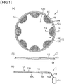
- Fig. 1(a) is a plan view of a drum head 1 used for a drum according to a first embodiment of the present invention
- Fig. 1(b) is a side view of the drum head 1
- Fig. 1(c) is a cross-sectional view taken along line IB-IB in Fig. 1(a) .
- the drum head 1 is mounted in one of openings of a cylindrical shell (a body) and used as a striking surface of the drum.
- the drum head 1 includes: a head portion 11 having a round shape and constituted by a skin formed of commonly used polyethylene terephthalate (PET) having a thickness of 250 ⁇ m; and a flesh hoop 14.
- PET polyethylene terephthalate
- the flesh hoop 14 is coupled to an outer edge of the head portion 11 to keep the round shape of the head portion 11.
- the flesh hoop 14 has an annular shape, and the inside diameter of the flesh hoop 14 is greater than the outside diameter of the shell 2.
- the head portion 11 includes: an effective vibration skin 12 inside an edge portion of the one-side opening of the shell; and an outer skin 13 formed integrally with an outer edge of the effective vibration skin 12 and provided outside the edge portion of the one-side opening of the shell.
- the effective vibration skin 12 effectively vibrates when struck in a state in which the drum head 1 is mounted in the one-side opening of the shell.
- the outer skin 13 extends from an outer edge of the effective vibration skin 12 so as to be inclined in the thickness direction of the effective vibration skin 12, toward an outside in the radial direction of the effective vibration skin 12.
- the present invention is not limited to this construction.
- the effective vibration skin 12 has an outer region 12A in which a plurality of openings 15 are formed.
- the outer region 12A is a region on the effective vibration skin 12 which is not to be struck or need not be struck in playing. This arrangement of the openings 15 reduces the area of the effective vibration skin 12, so that the volume of sound produced by strike on the present drum is less than that of sound produced by common drums.
- a region on the effective vibration skin 12 which is to be struck in playing will be referred to as "central region 12B".
- the drum head 1 is struck with drum sticks.
- the radius of the central region 12B is preferably set to 75 percent of the radius of the effective vibration skin 12, for example.
- each of the openings 15 is curved so as to protrude toward the center of the effective vibration skin 12.
- the dimension of the opening 15 in the radial direction of the effective vibration skin 12 is less than the dimension of the opening 15 in the circumferential direction of the effective vibration skin 12.
- the area of the opening 15 can be made large enough with enough area of the central region 12B.
- the openings 15 have the same shape and the same dimension.
- the area of each of the openings 15 in the effective vibration skin 12 is preferably greater than or equal to 78 mm 2 , for example.
- the openings 15 are spaced uniformly in the circumferential direction of the effective vibration skin 12. Since the openings 15 having the same shape and the same dimension are spaced uniformly, symmetry of the drum head 1 is well ensured, and all the vibrating modes of the struck drum head 1 can be brought closer to vibrating modes of a drum head not having the openings 15. Accordingly, a tone color of the sound produced by the drum installed with the drum head 1 is close to that of sound produced by a drum installed with a common drum head (the drum head not having the openings 15) when compared with sound produced by a drum installed with a drum head having openings with different shapes and sizes or a drum head having openings not uniformly spaced. It is noted that the drum installed with a common drum head may be referred to as "common drum".
- the drum head 1 has the striking surface (as one example of a first surface) as one of opposite surfaces of the drum head 1, and protective skins 16 for closing the respective openings 15 are provided on the other of the opposite surfaces of the drum head 1 for the respective openings 15.
- Each of the protective skins 16 is a thin skin shaped like a mesh.
- the protective skin 16 is formed by plain knitting of common PET fibers each having a fiber diameter of about 200 ⁇ m. This mesh shape provides the protective skins 16 with air permeability. Thus, even in the configuration in which the openings 15 are covered with the respective protective skins 16, no effects are given to flow of air into and out of the drum through the openings 15 with the drum is struck.
- each of the protective skins 16 is similar to that of each of the openings 15, but the area of the protective skin 16 is greater than that of the opening 15.
- the protective skins 16 are fixed to the drum head 1 such that outer edges of the respective protective skins 16 respectively surround outer edges of the respective openings 15.
- each of the protective skins 16 has a portion overlapping a region near a corresponding one of the openings 15. This overlapping portion is a fixed portion 16A.
- the fixed portion 16A serves as a sticking margin at which the protective skin 16 is fixed to the head portion 11.
- fixation of the protective skin 16 to the head portion 11 prevents separation of the protective skin 16 from the head portion 11 when the drum is struck. Examples of a method of this fixation include bonding and sticking.
- the method of this welding is as follows: ultrasonic vibration is caused to generate frictional heat on both of the fixed portions 16A and portions of the head portion 11 near the openings 15 to melt the fixed portions 16A and the portions of the head portion 11; and the melted fixed portions 16A and the melted portions of the head portion 11 are respectively compressed and bonded together to fix the head portion 11 and the protective skins 16 to each other.
- ultrasonic welding is employed as the method for fixing the protective skins 16 to the head portion 11 in the above-described embodiment, but, instead of the ultrasonic welding, hot melt may be used to fix the protective skins 16 to the head portion 11.
- hot-melt materials are disposed between the head portion 11 and the protective skins 16 and heated to melt the hot-melt materials.
- the melted hot-melt materials are combined with the head portion 11 and the protective skins 16, so that the protective skins 16 are fixed to the head portion 11.
- the hot-melt materials are formed of PET resin like the head portion 11 and the protective skins 16.
- One example of the hot-melt materials is PET resin having a thickness ranging between 25 ⁇ m and 100 ⁇ m and having a melting temperature of 150 degrees.
- the protective skins 16 can be well fixed to the head portion 11.
- the feature of the present embodiment is the protective skins 16 provided for closing the respective openings 15. Without the protective skins 16, the following situations may occur. Since the area of each of the openings 15 is large, the drum stick may be caught by the edge of the opening 15 by mistake when the drum is struck, which may lead to a hindrance to playing.
- a degree of stretch of the head portion 11 is adjusted (tuned) by a tensioner, not illustrated in Fig. 1 .
- the openings 15 are formed at the outer region 12A of the effective vibration skin 12, the head portion 11 cannot be tensioned uniformly.
- the effective vibration skin 12 is not vibrated uniformly when the drum is struck, and the tone color of sound produced by the strike is considerably different from that of sound produced by the common drum.
- the openings 15 are closed by the respective protective skins 16 in the drum head 1 according to the present embodiment.
- the drum head 1 when the drum is struck, a distal end of the drum stick is not caught by the edge of the opening 15, resulting in no hindrance to playing.
- the entire outer edge of the effective vibration skin 12 can be tensioned uniformly. Accordingly, the effective vibration skin 12 is vibrated uniformly when the drum is struck, and the tone color of sound produced by strike is close to that of sound produced by the common drum.
- the fixed portions 16A are fixed to the edge portions of the respective openings 15 in the drum head 1. This configuration increases the strength of the edge portions, resulting in reduced possibility of breakage of the drum head 1 from the portions of the effective vibration skin 12 near the openings 15 when the drum is struck.
- the openings 15 are formed at the outer region 12A of the effective vibration skin 12, the size of each of the openings 15 is large. This configuration can reduce or prevent a loss of energy in flow of air through the openings 15 into and out of the drum installed with the drum head 1. As a result, the length of sustain of sound produced by the strike is close to that of sustain of sound produced by the common drum.
- the openings 15 formed in the effective vibration skin 12 are closed by the respective protective skins 16, but the protective skins 16 have air permeability. Thus, no effects are given to the flow of air into and out of the drum through the openings 15, and the tone color of sound produced by strike is close to that of sound produced by the drum installed with the common drum head.
- the drum according to the present embodiment can reduce the possibility of breakage of the drum head due to strike and reduce the volume of sound produced by strike while achieving a tone color close to that of sound produced by the common drum. Since it is possible to achieve the tone color close to that of sound produced by the common drum, the drum installed with the drum head 1 can be used not only for practice but also for playing for an audience.
- the method of mounting the drum head 1 onto the drum is the same as that of mounting the common drum head onto the drum.
- the degree of stretch of the head portion 11 can be tuned with the tensioner in the same manner as that of the common drum.
- an amount of adjustment of the sound volume is determined by an opening ratio of the drum head 1. For example, increase in the opening ratio of the drum head 1 can decrease the volume of produced sound. Accordingly, various kinds of drum heads having different opening ratios can be prepared, and a player can select one of the drum heads which produces sound of a volume required for playing.
- Fig. 2(a) is a plan view of a drum head 2 used in a drum according to a second embodiment of the present invention
- Fig. 2(b) is a side view of the drum head 2
- Fig. 2(c) is a cross-sectional view taken along line IIB-IIB in Fig. 2(a)
- the same reference numerals as used in Fig. 2 are used to designate the corresponding elements in Fig. 1 .
- a difference between the drum head 1 and the drum head 2 is an annular protective skin 17 provided instead of the protective skins 16. There will be described the second embodiment, focusing on the protective skin 17.
- the protective skin 17 is a thin skin shaped like a mesh and is formed by plain knitting of PET fibers each having a fiber diameter of about 200 ⁇ m. That is, the protective skin 17 in the present embodiment is formed of the same PET resin of the head portion 11. Like the protective skins 16, the protective skin 17 gives no effects to the flow of air through the openings 15 into and out of the drum installed with the drum head 2.
- the shape of the protective skin 17 is an annular shape that is different from that of the protective skins 16.
- the protective skin 17 is provided along the outer edge of the effective vibration skin 12. Though the number of the protective skins 16 corresponds to the number of the openings 15, the single protective skin 17 is provided in the present embodiment.
- the protective skin 17 has a fixed portion 17A that does not overlap the openings 15.
- the fixed portion 17A serves as a sticking margin at which the protective skin 17 is fixed to the head portion 11.
- a method of fixation of the protective skin 17 is the same as that of fixation of the protective skins 16.
- the drum head 2 is easier than the drum head 1 in manufacture because the single protective skin 17 is provided on the drum head 2 while the protective skins 16 are provided for the respective openings 15 in the drum head 1.
- the drum head 2 according to the present embodiment is easier in manufacture than the drum head 1 according to the first embodiment.
Landscapes
- Physics & Mathematics (AREA)
- Engineering & Computer Science (AREA)
- Acoustics & Sound (AREA)
- Multimedia (AREA)
- Electrophonic Musical Instruments (AREA)
Applications Claiming Priority (2)
| Application Number | Priority Date | Filing Date | Title |
|---|---|---|---|
| JP2015195487 | 2015-09-30 | ||
| PCT/JP2016/077111 WO2017056993A1 (ja) | 2015-09-30 | 2016-09-14 | ドラムヘッドおよびドラム |
Publications (2)
| Publication Number | Publication Date |
|---|---|
| EP3358565A1 true EP3358565A1 (de) | 2018-08-08 |
| EP3358565A4 EP3358565A4 (de) | 2019-06-19 |
Family
ID=58423474
Family Applications (1)
| Application Number | Title | Priority Date | Filing Date |
|---|---|---|---|
| EP16851167.3A Withdrawn EP3358565A4 (de) | 2015-09-30 | 2016-09-14 | Trommelkopf und trommel |
Country Status (5)
| Country | Link |
|---|---|
| US (1) | US20190295516A1 (de) |
| EP (1) | EP3358565A4 (de) |
| JP (1) | JP6631634B2 (de) |
| CN (1) | CN108140368A (de) |
| WO (1) | WO2017056993A1 (de) |
Cited By (1)
| Publication number | Priority date | Publication date | Assignee | Title |
|---|---|---|---|---|
| WO2024215204A1 (en) * | 2023-04-13 | 2024-10-17 | Groen Beinte Jan Hein | Drum dampener |
Families Citing this family (7)
| Publication number | Priority date | Publication date | Assignee | Title |
|---|---|---|---|---|
| USD910110S1 (en) * | 2019-07-01 | 2021-02-09 | Cardinal Percussion, Ltd. | Percussion drum head |
| US11189255B2 (en) * | 2019-09-19 | 2021-11-30 | D'addario & Company, Inc. | Film formed snare and reduced volume snare drumhead |
| US11854514B2 (en) | 2019-10-23 | 2023-12-26 | D'addario & Company, Inc. | Drumhead with reduced volume |
| USD1012163S1 (en) * | 2020-03-05 | 2024-01-23 | Drummer Solutions LLC | Protective cover |
| USD948602S1 (en) * | 2020-10-26 | 2022-04-12 | Playcore Wisconsin, Inc. | Outdoor musical instrument |
| USD948603S1 (en) * | 2020-10-26 | 2022-04-12 | Playcore Wisconsin, Inc. | Outdoor musical instrument |
| CN114311900A (zh) * | 2022-01-12 | 2022-04-12 | 滁州学院 | 一种打击用的环保型多层鼓皮 |
Family Cites Families (19)
| Publication number | Priority date | Publication date | Assignee | Title |
|---|---|---|---|---|
| US4742753A (en) * | 1987-10-07 | 1988-05-10 | Zay Speed | Drumhead with framed aperture |
| GB2217091A (en) * | 1988-03-26 | 1989-10-18 | Adrian Stuart Cross | Rubber noise reducing pads for drums or cymbals |
| US5159139A (en) * | 1990-06-13 | 1992-10-27 | Evans Products, Inc. | Drumhead with overtone suppression |
| US5637819A (en) * | 1992-06-23 | 1997-06-10 | Rtom Corporation | Percussion instrument damping |
| US5581030A (en) * | 1996-02-16 | 1996-12-03 | Conroy; Douglas M. | Double pocket drum mute |
| US6172289B1 (en) * | 1998-01-05 | 2001-01-09 | Universal Percussion, Inc. | Drum head having auxiliary sound producing devices |
| JP3835084B2 (ja) * | 1999-11-15 | 2006-10-18 | ヤマハ株式会社 | ドラム、減音装置および電子打楽器用ヘッド |
| US6245979B1 (en) * | 1999-12-17 | 2001-06-12 | J. D'addario & Company, Inc. | Floating staccato waffle disk |
| US6700044B1 (en) * | 2002-09-30 | 2004-03-02 | Joseph Bencomo, Jr. | Adjustment assembly for a musical drum |
| CN2627615Y (zh) * | 2003-05-20 | 2004-07-21 | 陈明淮 | 鼓皮安全防护装置 |
| US8030562B2 (en) * | 2009-08-25 | 2011-10-04 | Remo, Inc. | Aroma drumhead |
| EP2509066A1 (de) * | 2011-04-06 | 2012-10-10 | Goodbuy Corporation S.A. | Elektromechanisches Schlaginstrument |
| JP5630618B2 (ja) * | 2012-07-27 | 2014-11-26 | ヤマハ株式会社 | スネアドラム |
| JP2015041090A (ja) * | 2013-08-23 | 2015-03-02 | ヤマハ株式会社 | ドラム |
| JP6221617B2 (ja) * | 2013-10-18 | 2017-11-01 | ヤマハ株式会社 | ドラム |
| US20170287452A1 (en) * | 2014-09-08 | 2017-10-05 | Christian VAIDA | Drum head with a plurality of cushioned openings |
| US9378714B1 (en) * | 2015-02-10 | 2016-06-28 | Kevin L. Baldwin, Sr. | Electronic drum |
| JP6477080B2 (ja) * | 2015-03-18 | 2019-03-06 | ヤマハ株式会社 | ドラムヘッド及びドラム |
| CN106128441A (zh) * | 2016-08-23 | 2016-11-16 | 宁波音王电声股份有限公司 | 一种非接触触发式网状电子鼓 |
-
2016
- 2016-09-14 JP JP2017543107A patent/JP6631634B2/ja active Active
- 2016-09-14 US US15/757,810 patent/US20190295516A1/en not_active Abandoned
- 2016-09-14 EP EP16851167.3A patent/EP3358565A4/de not_active Withdrawn
- 2016-09-14 CN CN201680057190.8A patent/CN108140368A/zh active Pending
- 2016-09-14 WO PCT/JP2016/077111 patent/WO2017056993A1/ja not_active Ceased
Cited By (2)
| Publication number | Priority date | Publication date | Assignee | Title |
|---|---|---|---|---|
| WO2024215204A1 (en) * | 2023-04-13 | 2024-10-17 | Groen Beinte Jan Hein | Drum dampener |
| NL2034569B1 (en) * | 2023-04-13 | 2024-10-21 | Jan Hein Groen Beinte | Drum dampener |
Also Published As
| Publication number | Publication date |
|---|---|
| JP6631634B2 (ja) | 2020-01-15 |
| CN108140368A (zh) | 2018-06-08 |
| WO2017056993A1 (ja) | 2017-04-06 |
| JPWO2017056993A1 (ja) | 2018-07-26 |
| US20190295516A1 (en) | 2019-09-26 |
| EP3358565A4 (de) | 2019-06-19 |
Similar Documents
| Publication | Publication Date | Title |
|---|---|---|
| EP3358565A1 (de) | Trommelkopf und trommel | |
| JP5987236B2 (ja) | 楽器及び枠体 | |
| TWI483621B (zh) | 揚聲器組合及其相位錐 | |
| JP4561960B2 (ja) | スピーカ用振動板 | |
| EP2704139B1 (de) | Trommelfell | |
| CN102592575A (zh) | 改进型乐鼓 | |
| JPH118895A (ja) | 対称指向性を有する指向性マイクロホン | |
| US20170287452A1 (en) | Drum head with a plurality of cushioned openings | |
| DE2803602B2 (de) | Elektroakustischer Wandler | |
| US6215053B1 (en) | Variable-thickness snare-side drumhead | |
| US6245979B1 (en) | Floating staccato waffle disk | |
| US20090013852A1 (en) | Musical Instrument Bell Cap | |
| US20170278492A1 (en) | Drum head and drum | |
| JP6477080B2 (ja) | ドラムヘッド及びドラム | |
| JP6569442B2 (ja) | ドラムおよびドラム用フープ | |
| JP2007088879A (ja) | スピーカ用振動板 | |
| JP2016021026A (ja) | ドラムヘッドおよびドラム | |
| KR101845978B1 (ko) | 관악기용 소리 보정기 | |
| US7274796B2 (en) | Reinforced speaker damper | |
| US7190804B2 (en) | Speaker apparatus | |
| US10462572B2 (en) | Acoustic transducer with vibration damping | |
| EP3843082B1 (de) | Trommelkopf und befestigungverfahren von dämpfungsschichten | |
| JP2016180966A (ja) | ドラム | |
| US20040104070A1 (en) | Speaker's damper with lead wire and guide sleeve | |
| IT201900010473A1 (it) | Pelle risonante per strumento musicale a percussione del tipo a tamburo |
Legal Events
| Date | Code | Title | Description |
|---|---|---|---|
| PUAI | Public reference made under article 153(3) epc to a published international application that has entered the european phase |
Free format text: ORIGINAL CODE: 0009012 |
|
| 17P | Request for examination filed |
Effective date: 20180427 |
|
| AK | Designated contracting states |
Kind code of ref document: A1 Designated state(s): AL AT BE BG CH CY CZ DE DK EE ES FI FR GB GR HR HU IE IS IT LI LT LU LV MC MK MT NL NO PL PT RO RS SE SI SK SM TR |
|
| AX | Request for extension of the european patent |
Extension state: BA ME |
|
| DAV | Request for validation of the european patent (deleted) | ||
| DAX | Request for extension of the european patent (deleted) | ||
| A4 | Supplementary search report drawn up and despatched |
Effective date: 20190521 |
|
| RIC1 | Information provided on ipc code assigned before grant |
Ipc: G10D 13/00 20060101AFI20190515BHEP Ipc: G10D 13/02 20060101ALI20190515BHEP |
|
| STAA | Information on the status of an ep patent application or granted ep patent |
Free format text: STATUS: THE APPLICATION IS DEEMED TO BE WITHDRAWN |
|
| 18D | Application deemed to be withdrawn |
Effective date: 20191218 |