EP3358665B1 - Bloc de piles rechargeables - Google Patents
Bloc de piles rechargeables Download PDFInfo
- Publication number
- EP3358665B1 EP3358665B1 EP16851455.2A EP16851455A EP3358665B1 EP 3358665 B1 EP3358665 B1 EP 3358665B1 EP 16851455 A EP16851455 A EP 16851455A EP 3358665 B1 EP3358665 B1 EP 3358665B1
- Authority
- EP
- European Patent Office
- Prior art keywords
- power storage
- pack
- charge
- storage pack
- curve
- Prior art date
- Legal status (The legal status is an assumption and is not a legal conclusion. Google has not performed a legal analysis and makes no representation as to the accuracy of the status listed.)
- Active
Links
Images












Classifications
-
- H—ELECTRICITY
- H01—ELECTRIC ELEMENTS
- H01M—PROCESSES OR MEANS, e.g. BATTERIES, FOR THE DIRECT CONVERSION OF CHEMICAL ENERGY INTO ELECTRICAL ENERGY
- H01M10/00—Secondary cells; Manufacture thereof
- H01M10/42—Methods or arrangements for servicing or maintenance of secondary cells or secondary half-cells
- H01M10/44—Methods for charging or discharging
- H01M10/441—Methods for charging or discharging for several batteries or cells simultaneously or sequentially
-
- H—ELECTRICITY
- H01—ELECTRIC ELEMENTS
- H01M—PROCESSES OR MEANS, e.g. BATTERIES, FOR THE DIRECT CONVERSION OF CHEMICAL ENERGY INTO ELECTRICAL ENERGY
- H01M10/00—Secondary cells; Manufacture thereof
- H01M10/05—Accumulators with non-aqueous electrolyte
- H01M10/052—Li-accumulators
- H01M10/0525—Rocking-chair batteries, i.e. batteries with lithium insertion or intercalation in both electrodes; Lithium-ion batteries
-
- H—ELECTRICITY
- H01—ELECTRIC ELEMENTS
- H01M—PROCESSES OR MEANS, e.g. BATTERIES, FOR THE DIRECT CONVERSION OF CHEMICAL ENERGY INTO ELECTRICAL ENERGY
- H01M10/00—Secondary cells; Manufacture thereof
- H01M10/05—Accumulators with non-aqueous electrolyte
- H01M10/058—Construction or manufacture
-
- H—ELECTRICITY
- H01—ELECTRIC ELEMENTS
- H01M—PROCESSES OR MEANS, e.g. BATTERIES, FOR THE DIRECT CONVERSION OF CHEMICAL ENERGY INTO ELECTRICAL ENERGY
- H01M10/00—Secondary cells; Manufacture thereof
- H01M10/42—Methods or arrangements for servicing or maintenance of secondary cells or secondary half-cells
- H01M10/44—Methods for charging or discharging
-
- H—ELECTRICITY
- H01—ELECTRIC ELEMENTS
- H01M—PROCESSES OR MEANS, e.g. BATTERIES, FOR THE DIRECT CONVERSION OF CHEMICAL ENERGY INTO ELECTRICAL ENERGY
- H01M16/00—Structural combinations of different types of electrochemical generators
-
- H—ELECTRICITY
- H01—ELECTRIC ELEMENTS
- H01M—PROCESSES OR MEANS, e.g. BATTERIES, FOR THE DIRECT CONVERSION OF CHEMICAL ENERGY INTO ELECTRICAL ENERGY
- H01M4/00—Electrodes
- H01M4/02—Electrodes composed of, or comprising, active material
- H01M4/13—Electrodes for accumulators with non-aqueous electrolyte, e.g. for lithium-accumulators; Processes of manufacture thereof
- H01M4/131—Electrodes based on mixed oxides or hydroxides, or on mixtures of oxides or hydroxides, e.g. LiCoOx
-
- H—ELECTRICITY
- H01—ELECTRIC ELEMENTS
- H01M—PROCESSES OR MEANS, e.g. BATTERIES, FOR THE DIRECT CONVERSION OF CHEMICAL ENERGY INTO ELECTRICAL ENERGY
- H01M4/00—Electrodes
- H01M4/02—Electrodes composed of, or comprising, active material
- H01M4/36—Selection of substances as active materials, active masses, active liquids
- H01M4/362—Composites
- H01M4/364—Composites as mixtures
-
- H—ELECTRICITY
- H01—ELECTRIC ELEMENTS
- H01M—PROCESSES OR MEANS, e.g. BATTERIES, FOR THE DIRECT CONVERSION OF CHEMICAL ENERGY INTO ELECTRICAL ENERGY
- H01M4/00—Electrodes
- H01M4/02—Electrodes composed of, or comprising, active material
- H01M4/36—Selection of substances as active materials, active masses, active liquids
- H01M4/48—Selection of substances as active materials, active masses, active liquids of inorganic oxides or hydroxides
-
- H—ELECTRICITY
- H01—ELECTRIC ELEMENTS
- H01M—PROCESSES OR MEANS, e.g. BATTERIES, FOR THE DIRECT CONVERSION OF CHEMICAL ENERGY INTO ELECTRICAL ENERGY
- H01M4/00—Electrodes
- H01M4/02—Electrodes composed of, or comprising, active material
- H01M4/36—Selection of substances as active materials, active masses, active liquids
- H01M4/48—Selection of substances as active materials, active masses, active liquids of inorganic oxides or hydroxides
- H01M4/50—Selection of substances as active materials, active masses, active liquids of inorganic oxides or hydroxides of manganese
- H01M4/505—Selection of substances as active materials, active masses, active liquids of inorganic oxides or hydroxides of manganese of mixed oxides or hydroxides containing manganese for inserting or intercalating light metals, e.g. LiMn2O4 or LiMn2OxFy
-
- H—ELECTRICITY
- H01—ELECTRIC ELEMENTS
- H01M—PROCESSES OR MEANS, e.g. BATTERIES, FOR THE DIRECT CONVERSION OF CHEMICAL ENERGY INTO ELECTRICAL ENERGY
- H01M4/00—Electrodes
- H01M4/02—Electrodes composed of, or comprising, active material
- H01M4/36—Selection of substances as active materials, active masses, active liquids
- H01M4/48—Selection of substances as active materials, active masses, active liquids of inorganic oxides or hydroxides
- H01M4/52—Selection of substances as active materials, active masses, active liquids of inorganic oxides or hydroxides of nickel, cobalt or iron
- H01M4/525—Selection of substances as active materials, active masses, active liquids of inorganic oxides or hydroxides of nickel, cobalt or iron of mixed oxides or hydroxides containing iron, cobalt or nickel for inserting or intercalating light metals, e.g. LiNiO2, LiCoO2 or LiCoOxFy
-
- H—ELECTRICITY
- H01—ELECTRIC ELEMENTS
- H01M—PROCESSES OR MEANS, e.g. BATTERIES, FOR THE DIRECT CONVERSION OF CHEMICAL ENERGY INTO ELECTRICAL ENERGY
- H01M4/00—Electrodes
- H01M4/02—Electrodes composed of, or comprising, active material
- H01M4/36—Selection of substances as active materials, active masses, active liquids
- H01M4/58—Selection of substances as active materials, active masses, active liquids of inorganic compounds other than oxides or hydroxides, e.g. sulfides, selenides, tellurides, halogenides or LiCoFy; of polyanionic structures, e.g. phosphates, silicates or borates
-
- H—ELECTRICITY
- H01—ELECTRIC ELEMENTS
- H01M—PROCESSES OR MEANS, e.g. BATTERIES, FOR THE DIRECT CONVERSION OF CHEMICAL ENERGY INTO ELECTRICAL ENERGY
- H01M4/00—Electrodes
- H01M4/02—Electrodes composed of, or comprising, active material
- H01M4/36—Selection of substances as active materials, active masses, active liquids
- H01M4/58—Selection of substances as active materials, active masses, active liquids of inorganic compounds other than oxides or hydroxides, e.g. sulfides, selenides, tellurides, halogenides or LiCoFy; of polyanionic structures, e.g. phosphates, silicates or borates
- H01M4/5825—Oxygenated metallic salts or polyanionic structures, e.g. borates, phosphates, silicates, olivines
-
- H—ELECTRICITY
- H01—ELECTRIC ELEMENTS
- H01M—PROCESSES OR MEANS, e.g. BATTERIES, FOR THE DIRECT CONVERSION OF CHEMICAL ENERGY INTO ELECTRICAL ENERGY
- H01M50/00—Constructional details or processes of manufacture of the non-active parts of electrochemical cells other than fuel cells, e.g. hybrid cells
- H01M50/20—Mountings; Secondary casings or frames; Racks, modules or packs; Suspension devices; Shock absorbers; Transport or carrying devices; Holders
- H01M50/204—Racks, modules or packs for multiple batteries or multiple cells
-
- H—ELECTRICITY
- H02—GENERATION; CONVERSION OR DISTRIBUTION OF ELECTRIC POWER
- H02J—ELECTRIC POWER NETWORKS; CIRCUIT ARRANGEMENTS OR SYSTEMS FOR SUPPLYING OR DISTRIBUTING ELECTRIC POWER; SYSTEMS FOR STORING ELECTRIC ENERGY
- H02J7/00—Circuit arrangements for charging or discharging batteries or for supplying loads from batteries
-
- H—ELECTRICITY
- H01—ELECTRIC ELEMENTS
- H01M—PROCESSES OR MEANS, e.g. BATTERIES, FOR THE DIRECT CONVERSION OF CHEMICAL ENERGY INTO ELECTRICAL ENERGY
- H01M10/00—Secondary cells; Manufacture thereof
- H01M10/06—Lead-acid accumulators
-
- H—ELECTRICITY
- H01—ELECTRIC ELEMENTS
- H01M—PROCESSES OR MEANS, e.g. BATTERIES, FOR THE DIRECT CONVERSION OF CHEMICAL ENERGY INTO ELECTRICAL ENERGY
- H01M10/00—Secondary cells; Manufacture thereof
- H01M10/34—Gastight accumulators
- H01M10/345—Gastight metal hydride accumulators
-
- Y—GENERAL TAGGING OF NEW TECHNOLOGICAL DEVELOPMENTS; GENERAL TAGGING OF CROSS-SECTIONAL TECHNOLOGIES SPANNING OVER SEVERAL SECTIONS OF THE IPC; TECHNICAL SUBJECTS COVERED BY FORMER USPC CROSS-REFERENCE ART COLLECTIONS [XRACs] AND DIGESTS
- Y02—TECHNOLOGIES OR APPLICATIONS FOR MITIGATION OR ADAPTATION AGAINST CLIMATE CHANGE
- Y02E—REDUCTION OF GREENHOUSE GAS [GHG] EMISSIONS, RELATED TO ENERGY GENERATION, TRANSMISSION OR DISTRIBUTION
- Y02E60/00—Enabling technologies; Technologies with a potential or indirect contribution to GHG emissions mitigation
- Y02E60/10—Energy storage using batteries
-
- Y—GENERAL TAGGING OF NEW TECHNOLOGICAL DEVELOPMENTS; GENERAL TAGGING OF CROSS-SECTIONAL TECHNOLOGIES SPANNING OVER SEVERAL SECTIONS OF THE IPC; TECHNICAL SUBJECTS COVERED BY FORMER USPC CROSS-REFERENCE ART COLLECTIONS [XRACs] AND DIGESTS
- Y02—TECHNOLOGIES OR APPLICATIONS FOR MITIGATION OR ADAPTATION AGAINST CLIMATE CHANGE
- Y02P—CLIMATE CHANGE MITIGATION TECHNOLOGIES IN THE PRODUCTION OR PROCESSING OF GOODS
- Y02P70/00—Climate change mitigation technologies in the production process for final industrial or consumer products
- Y02P70/50—Manufacturing or production processes characterised by the final manufactured product
-
- Y—GENERAL TAGGING OF NEW TECHNOLOGICAL DEVELOPMENTS; GENERAL TAGGING OF CROSS-SECTIONAL TECHNOLOGIES SPANNING OVER SEVERAL SECTIONS OF THE IPC; TECHNICAL SUBJECTS COVERED BY FORMER USPC CROSS-REFERENCE ART COLLECTIONS [XRACs] AND DIGESTS
- Y02—TECHNOLOGIES OR APPLICATIONS FOR MITIGATION OR ADAPTATION AGAINST CLIMATE CHANGE
- Y02T—CLIMATE CHANGE MITIGATION TECHNOLOGIES RELATED TO TRANSPORTATION
- Y02T10/00—Road transport of goods or passengers
- Y02T10/60—Other road transportation technologies with climate change mitigation effect
- Y02T10/70—Energy storage systems for electromobility, e.g. batteries
Definitions
- the present invention relates to a power storage pack.
- Lead storage batteries are widely used in various applications, such as in-car applications for driving automobiles or for use as power supply to various types of electric loads, industrial applications for use as backup power supplies for commercial power supplies, and electric vehicle applications for use as main power supplies for golf carts, forklifts, and the like.
- Lead storage batteries are commonly used, such as six batteries connected in series for 12 V, and batteries configured for 24 V, 36 V, 48 V, 60 V, 72 V, and the like as multiples of 12 V.
- Lead storage batteries are low in price as compared with storage batteries such as lithium ion storage batteries and nickel-metal-hydride storage batteries, but inferior in charge/discharge cycle characteristics as compared with the storage batteries.
- lead storage batteries have charge/discharge cycle characteristics degraded significantly on reaching an overcharge state or an overdischarge state. For example, when a lead storage battery reaches an overcharge state, gas generation and a decrease in amount of electrolytic solution, corrosion of a current collector, and loss of an active material due to electrolysis of sulfuric acid as an electrolytic solution will be caused, thereby degrading charge/discharge cycle characteristics.
- Japanese Patent Application 2007-131134 proposes a power storage system where an inexpensive lead storage battery and a high-performance storage battery which is superior in charge/discharge cycle characteristics to the lead storage battery are connected in parallel.
- the DC-DC converter is high in price and large in size, and the power storage system described in JP2007-131134 , which is provided with the DC-DC converter, is thus high in price and large in size.
- US 2011/086248 discloses an assembled battery including a combination of two kinds of secondary batteries differing in battery property (charge voltage behavior), each secondary battery including a positive electrode, a negative electrode, a separator interposed between the positive and negative electrodes, and a non-aqueous electrolyte.
- US 2011/086248 relates to an assembled battery including at least one first cell and at least one second cell electrically connected in series. The second cell has a greater change in charge voltage at the end of charge and a larger cell capacity.
- EP3223336 discloses an on-vehicle battery including a lead storage battery and a second storage battery.
- the second storage battery is connected in parallel with the lead storage battery.
- the second storage battery has a positive electrode and a negative electrode.
- the positive electrode includes, as a positive electrode active material, a spinel-type lithium-nickel-manganese oxide.
- the negative electrode includes, as a negative electrode active material, at least one of graphite, soft carbon, hard carbon, and an alloy-based material containing an Si element.
- a first power storage pack according to the present invention is for connection in parallel with a second power storage pack with a different battery chemistry and without any DC-DC converter interposed between the first power storage pack and the second power storage pack.
- a charge/discharge curve of the first power storage pack measured with a constant C-rate has a step passing through a range of (12.5 ⁇ n) V or higher and (12.8 ⁇ n) V or lower, where n is a natural number of 1 or more and 125 or less.
- an average discharge voltage falls within a range of (9.0 ⁇ n) V or higher and (12.5 ⁇ n) V or lower and/or a voltage at a peak top obtained on a dQ/dV curve obtained by differentiating the discharge curve with respect to voltage falls within a range of (9.0 ⁇ n) V or higher and (12.5 ⁇ n) V or lower.
- an average charge voltage falls within the range of (12.8 ⁇ n) V or higher and (14.8 ⁇ n) V or lower and/or a voltage at a peak top obtained on a dQ/dV curve obtained by differentiating the charge curve with respect to voltage falls within the range of (12.8 ⁇ n) V or higher and (14.8 ⁇ n) V or lower.
- a step of a charge or discharge curve refers to a range in which the proportion of the amount of change in voltage, ⁇ V, on the charge/discharge curve to the amount of change in SOC, ⁇ SOC, is (100 ⁇ n) mV/% or more, when the SOC is in the range of 5% to 95%.
- the start point of a step is the minimum voltage of a discharge curve in the range of one step, and the corresponding value of the SOC at the minimum voltage
- the end point of the step is the maximum voltage of a charge curve in the range of the same step, and the corresponding value of the SOC at the maximum voltage.
- the first power storage pack according to the present invention connected in parallel to a second power storage pack with 6 ⁇ n lead storage batteries connected in series.
- the second power storage pack with the 6 ⁇ n lead storage batteries connected in series represents a lead storage battery pack configured for a multiple of 12 V.
- the second power storage pack with the 6 ⁇ n lead storage batteries connected in series represents a lead storage battery pack configured for 12 V with six lead storage batteries connected in series.
- the second power storage pack with the 6 ⁇ n lead storage batteries connected in series represents a lead storage battery pack configured for 24 V with twelve lead storage batteries connected in series, or a lead storage battery pack configured for 24 V with two series-connected lead storage batteries each configured for 12 V.
- n 3 or more.
- the first power storage pack according to the present invention has a step passing through the range of (12.5 ⁇ n) V or higher and (12.8 ⁇ n) V or lower (n is a natural number of 1 or more and 125 or less). For this reason, for example, in a power storage system in which a second power storage pack with 6 ⁇ n lead storage batteries connected in series is connected in parallel to the first power storage pack according to the present invention, when the voltage of the lead storage battery pack falls within the voltage range in normal use, the voltage of the first power storage pack according to the present invention substantially coincides with the voltage of the lead storage battery pack at the step of the charge/discharge curve for the first power storage pack according to the present invention.
- the generation of a large voltage difference is eliminated between the power storage pack according to the present invention and the lead storage battery pack. Therefore, there is not always a need to provide a DC-DC converter between the first power storage pack according to the present invention and the lead storage battery pack. Accordingly, for example, the use of the first power storage pack according to the present invention makes it possible to reduce the price of a power storage system including the lead storage battery pack, and reduce the size thereof.
- the average discharge voltage on the lower SOC side than the start point of the step of the charge/discharge curve for the first power storage pack according to the present invention falls within the range of (9.0 ⁇ n) V or higher and (12.5 ⁇ n) V or lower. For this reason, when the power storage system with the parallel-connected power storage packs each with the 6 ⁇ n lead storage batteries connected in series is required for large current output, the output from the power storage packs according to the present invention is also provided in a condition in which the voltage of the lead storage battery pack is lower than the voltage range in normal use, thereby making it possible to prevent the voltage of the lead storage battery pack from being lower than the discharge cutoff voltage.
- the average charge voltage on the higher SOC side than the end point of the step of the charge/discharge curve for the first power storage pack according to the present invention falls within the range of (12.8 ⁇ n) V or higher and (14.8 ⁇ n) V or lower. For this reason, when the power storage system with the parallel-connected power storage packs each with the 6 ⁇ n lead storage batteries connected in series is required for large current input, the input to the power storage packs according to the present invention is also provided in a condition in which the voltage of the lead storage battery pack is higher than the voltage range in normal use, thereby making it possible to prevent the voltage of the lead storage battery pack from being higher than the charge cutoff voltage.
- the charge/discharge curve for a first power storage pack according to the present invention has a step passing through the range of (12.5 ⁇ n) V or higher and (12.8 ⁇ n) V or lower (n is a natural number of 1 or more and 125 or less).
- n is a natural number of 1 or more and 125 or less.
- the voltage at the peak top obtained on the curve (dQ/dV curve) obtained by differentiating, with respect to voltage, the discharge curve for the first power storage pack falls within the range of (9.0 ⁇ n) V or higher and (12.5 ⁇ n) V or lower.
- the voltage at the peak top obtained on the curve (dQ/dV curve) obtained by differentiating, with respect to voltage, the charge curve for the first power storage pack falls within the range of (12.8 ⁇ n) V or higher and (14.8 ⁇ n) V or lower.
- the first power storage pack according to the present invention connected in parallel to a second power storage pack with 6 ⁇ n lead storage batteries connected in series.
- the first power storage pack according to the present invention has a step passing through the range of (12.5 ⁇ n) V or higher and (12.8 ⁇ n) V or lower (n is a natural number of 1 or more and 125 or less). For this reason, for example, in a power storage system in which a second power storage pack with 6 ⁇ n lead storage batteries connected in series is connected in parallel to the first power storage pack according to the present invention, when the voltage of the lead storage battery pack falls within the voltage range in normal use, the voltage of the first power storage pack according to the present invention substantially coincides with the voltage of the lead storage battery pack at the step of the charge/discharge curve for the first power storage pack according to the present invention.
- the use of the first power storage pack according to the present invention makes it possible to reduce the price of a power storage system including the lead storage battery pack, and reduce the size thereof.
- the voltage at the peak top obtained on the curve (dQ/dV curve) obtained by differentiating, with respect to voltage, the discharge curve for the first power storage pack falls within the range of (9.0 ⁇ n) V or higher and (12.5 ⁇ n) V or lower.
- the output from the power storage packs according to the present invention is also provided in a condition in which the voltage of the lead storage battery pack is lower than the voltage range in normal use, thereby making it possible to prevent the voltage of the lead storage battery pack from being lower than the discharge cutoff voltage. Therefore, deterioration due to an overdischarge state of the lead storage battery pack can be prevented, thereby allowing an increase in the life-span of the power storage system. In addition, there is no need for a special circuit for preventing an overdischarge state of the lead storage battery pack, thus allowing a reduction in the price of the power storage system.
- the voltage at the peak top obtained on the curve (dQ/dV curve) obtained by differentiating, with respect to voltage, the charge curve for the first power storage pack falls within the range of (12.8 ⁇ n) V or higher and (14.8 ⁇ n) V or lower.
- the input to the power storage packs according to the present invention is also provided in a condition in which the voltage of the lead storage battery pack is higher than the voltage range in normal use, thereby making it possible to prevent the voltage of the lead storage battery pack from being higher than the charge cutoff voltage. Therefore, deterioration due to an overcharge state of the lead storage battery pack can be prevented, thereby allowing an increase in the life-span of the power storage system. In addition, there is no need for a special circuit for preventing an overcharge state of the lead storage battery pack, thus allowing a reduction in the price of the power storage system.
- the first power storage pack according to the present invention may include a power storage device, and the power storage device may be a lithium ion storage battery or a nickel-metal-hydride storage battery.
- the first power storage pack according to the present invention may include a lithium ion storage battery, and the lithium ion storage battery may have a positive electrode including multiple kinds of positive electrode active materials.
- the first power storage pack according to the present invention may include a lithium ion storage battery, and the lithium ion storage battery may have a negative electrode including multiple kinds of negative electrode active materials.
- the first power storage pack according to the present invention may be composed of a plurality of power storage modules connected in parallel, which is composed of a plurality of power storage devices connected in series, and the plurality of power storage modules may include power storage modules that differ from each other in number of connection stages.
- the first power storage pack according to the present invention may include multiple types of power storage modules that have different types of power storage devices.
- the ratio preferably falls within the range of 10 : 90 to 90 : 10 between the capacity on the lower SOC side than the start point of a step of the charge/discharge curve for the first power storage pack according to the present invention and the capacity on the higher SOC side than the end point of the step of the charge/discharge curve for the first power storage pack.
- an increase in the life-span of a power storage system, a reduction in the price thereof, and a reduction in the size thereof can be achieved.
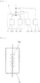
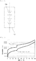
- FIG. 1 is a schematic circuit diagram of a vehicle according to the present embodiment.
- the vehicle 2 shown in FIG. 1 includes a power storage system 1.
- the power storage system 1 is used in a preferred manner, for example, for a power supply of a vehicle such as an automobile, a golf cart, a forklift, a rail vehicle, or an airplane, a transfer means such as a ship, or a transport means.
- the power storage system 1 is also used in a preferred manner as a power supply for an idling stop mechanism of an automobile that has the idling stop mechanism.
- the power storage system 1 is preferred for, in particular, electric vehicles such as a golf cart, a forklift, an electric wheelchair, a walker for an aged person, an electric scooter, an electric bicycle, an electric cart, an electric car, a Low Speed Vehicle (LSV), and an automated guided vehicle (AGV), which include a lead storage battery as a main power supply, and automobiles that have an idling stop function.
- electric vehicles such as a golf cart, a forklift, an electric wheelchair, a walker for an aged person, an electric scooter, an electric bicycle, an electric cart, an electric car, a Low Speed Vehicle (LSV), and an automated guided vehicle (AGV), which include a lead storage battery as a main power supply, and automobiles that have an idling stop function.
- LSV Low Speed Vehicle
- AGV automated guided vehicle
- the power storage system 1 is also preferred in power storage applications for power generators such as wind power generators, solar power generators, fuel cells, diesel generators, gasoline generators, and gas power generators.
- power generators such as wind power generators, solar power generators, fuel cells, diesel generators, gasoline generators, and gas power generators.
- the power storage system 1 includes a second power storage pack 11 and a first power storage pack 12.
- the second power storage pack 11 is a lead storage battery pack.
- the second power storage pack 11 is a power storage pack with 6 ⁇ n (n is a natural number of 1 or more and 125 or less) lead storage batteries connected in series will be described below in the present embodiment.
- the voltage range in normal use of the second power storage pack 11 is approximately (12.5 ⁇ n) V or higher and (12.8 ⁇ n) V or lower.
- the discharge cutoff voltage of the second power storage pack 11 is approximately (9.0 ⁇ n) V.
- the charge cutoff voltage of the second power storage pack 11 is approximately (14.8 ⁇ n) V.
- the first power storage pack 12 is connected in parallel to the second power storage pack 11. Specifically, the second power storage pack 11 and the first power storage pack are connected in parallel without any DCDC converter interposed therebetween.
- the first power storage pack 12 can be composed of, for example, a power storage pack such as a lithium ion storage battery pack and a nickel-metal-hydride storage battery pack.
- the first power storage pack 12 can be also composed of a capacitor such as a lithium ion capacitor (LIC) or an electric double layer capacitor (EDLC).
- LIC lithium ion capacitor
- EDLC electric double layer capacitor
- the "power storage device” means a storage battery such as a lead storage battery, a lithium ion storage battery, and a nickel-metal-hydride storage battery, and a unit cell such as a capacitor.
- the "power storage pack” includes at least one power storage device.
- a pack composed of at least one storage battery is referred to as a "storage battery pack".
- the lithium ion storage battery pack means a storage battery pack composed of at least one lithium ion storage battery.
- the lead storage battery pack means a storage battery pack composed of at least one lead storage battery.
- the nickel-metal-hydride storage battery pack means a storage battery pack composed of at least one nickel-metal-hydride storage battery.
- the power storage pack may be composed of one power storage module.
- the power storage pack may be composed of a plurality of power storage modules connected in parallel.
- the power storage pack may have a power storage module connected in parallel to at least one of a plurality of power storage modules connected in series.
- the "power storage module” means at least one power storage device connected in series. Accordingly, the power storage pack can have a power storage module.
- the plurality of power storage devices may have the same type of devices, or include multiple types of power storage devices.
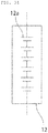
- first power storage pack 12 As shown in FIG. 2 , an example of the first power storage pack 12 with a plurality of power storage devices 12a connected in series will be described in the present embodiment. Specifically, an example of the first power storage pack 12 composed of four lithium ion storage batteries 12a connected in series will be described in the present embodiment.
- the first power storage pack is not necessarily required to be composed of one power storage module.
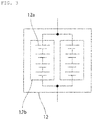
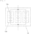
- a plurality of power storage modules 12b may be connected in parallel in the first power storage pack 12.
- a power storage module may be connected in parallel to at least one of a plurality of power storage modules 12b connected in series in the first power storage pack 12.
- each of the first and second power storage packs 11, 12 may further have a control unit for controlling a battery constituting each of the packs 11, 12.
- examples of a positive electrode active material included in a positive electrode of the lithium ion storage battery include inorganic compounds such as a composite oxide of a transition metal and lithium, a transition metal oxide, and a transition metal sulfide, and organic compounds.
- Examples of a negative electrode active material included in a negative electrode of the lithium ion storage battery include inorganic compounds such as a composite oxide of a transition metal and lithium, a metal oxide, an alloy material, and a transition metal sulfide, carbon materials, organic compounds, and lithium metals.
- the examples include composite oxides of transition metals and lithium, such as LiMn 2 O 4 , Li 4 Ti 5 O 12 , Li 2 Ti 3 O 7 , LiMg 1/2 Ti 3/2 O 4 , LiCo 1/2 Ti 3/2 O 4 , LiZn 1/2 Ti 3/2 O 4 , LiFeTiO 4 , LiCrTiO 4 , Li 2 SrTi e O 14 , and Li 2 BaTi 6 O 14 ; metal oxides such as TiO 2 , WO 3 , MoO 2 , MnO 2 , V 2 O 5 , SiO 2 , SiO, and SnO 2 ; alloy materials of Si, Sn, or the like; transition metal sulfides such as FeS and TiS; carbon materials such as graphite, non-graphitizable carbon, and graphitizable carbon; and organic compounds such as quinone compounds, disulfide compounds, diazine compounds, radialene compounds, rubeanic acid compounds, and organic radical compounds.
- the above-mentioned compounds with transition metal elements substituted with different types of elements may be used for the inorganic compounds.
- One of these negative electrode active materials may be used alone, or two or more thereof may be used concurrently.
- the above-mentioned negative electrode active materials subjected to pre-doping treatment with lithium ions may be used for the negative electrode active material.
- an electric load 13 composed of a motor or the like and a recharger 14 are connected in parallel to the power storage system 1. Between the power storage system 1 and each of the electric load 13 and the recharger 14, a switch is provided.
- a fuse or an FET switch may be provided between the second power storage pack 11 and the first power storage pack 12, if necessary.
- the electric power supplied from the recharger 14 is supplied to the second power storage pack 11 and the first power storage pack 12.
- electric power is supplied from the second power storage pack 11 and the first power storage pack 12 to the electric load 13.
- the second power storage pack 11 and the first power storage pack 12 are provided with a control device, if necessary, to be controlled such that no abnormality occurs, such as an overcharge/overdischarge state or overheat.
- the electric load 13 is specifically an electric motor, and during deceleration of the vehicle 2, decelerating regeneration is carried out in which regenerative energy is converted to electrical energy by the electric motor as the electric load 13 to charge the second power storage pack 11 and the first power storage pack 12.
- the power storage system 1 satisfies the following conditions (a), (b), and (c).
- the power storage system 1 satisfies the following conditions (d) and (e).
- the step of a charge/discharge curve refers to a range in which the voltage varies significantly in the range of 5% to 95% in the SOC of the first power storage pack 12, and specifically, refers to a range in which the absolute value of ⁇ V/ ⁇ SOC that is the proportion of the amount of change in voltage ( ⁇ V) on at least one of the charge curve or the discharge curve to the amount of change in SOC ( ⁇ SOC) is (100 ⁇ n) mV/% or more in the range of 5% to 95% in the SOC.
- the start point of a step means the minimum voltage of a discharge curve in the range of one step, and the SOC at the voltage.
- the end point of the step means the maximum voltage of a charge curve in the range of the same step, and the SOC at the voltage.
- the charge/discharge curve for the first power storage pack 12 refers to a charge/discharge curve in the case of constant-current charging/discharging in the voltage range from a discharge cutoff voltage to a charge cutoff voltage at a current value of 0.2 C under the condition of 25°C ⁇ 5°C.
- the "current value of 1 C” refers to a current value for charging or discharging to a rating capacity for 1 hour.
- the dQ/dV curve for the first power storage pack 12 refers to a curve (dQ/dV curve) obtained by differentiating the charge/discharge curve for the first power storage pack 12 with respect to voltage.
- the first power storage pack 12 according to the present embodiment satisfies all of the conditions (a), (b), (c), (d), and (e), but there is no need to limit the present invention thereto.
- the first power storage pack according to the present invention may satisfy only the conditions (a), (b), and (c).
- the first power storage pack according to the present invention may satisfy only the conditions (a), (d), and (e).
- the power storage system 1 satisfies the condition (a). For this reason, when the voltage of the second power storage pack 11 falls within the voltage range in normal use, the voltage of the first power storage pack 12 substantially coincides with the voltage of the second power storage pack 11 at the step of the charge/discharge curve for the first power storage pack 12, and the generation of a large voltage difference is eliminated between the first power storage pack 12 and the second power storage pack 11. Therefore, there is not always a need to provide a DCDC converter between the first power storage pack 12 and the second power storage pack 11. Accordingly, it becomes possible to reduce the price of the power storage system 1 and reduce the size thereof.
- the power storage system 1 satisfies at least one of the condition (b) and the condition (d). For this reason, when the first power storage pack 12 is required for large current output, the output from the first power storage pack 12 is also provided in a condition in which the voltage of the second power storage pack 11 is lower than the voltage range in normal use. Therefore, the voltage of the second power storage pack 11 can be prevented from being lower than the discharge cutoff voltage. Consequently, deterioration due to an overdischarge state of the second power storage pack 11 can be prevented, thereby allowing an increase in the life-span of the power storage system 1. In addition, there is not always a need for a special circuit for preventing an overdischarge state of the second power storage pack 11, thus allowing a reduction in the price of the power storage system 1.
- the power storage system 1 satisfies at least one of the condition (c) and the condition (e). For this reason, when the power storage system 1 is required for large current input, the input to the first power storage pack 12 is also provided in a condition in which the voltage of the second power storage pack 11 is higher than the voltage range in normal use. Consequently, the voltage of the second power storage pack 11 can be prevented from being higher than the charge cutoff voltage. Therefore, deterioration due to an overcharge state of the second power storage pack 11 can be prevented, thereby allowing an increase in the life-span of the power storage system 1. In addition, there is no need for a special circuit for preventing an overcharge state of the second power storage pack 11, thus allowing a reduction in the price of the power storage system 1.
- the negative electrode active material that causes a charge/discharge curve for the lithium ion storage battery to have a step include, for example, LiMn 2 O 4 , Li 4 Ti 5 O 12 , LiMg 1/2 Ti 3/2 O 4 , LiCo 1/2 Ti 3/2 O 4 , LiZn 1/2 Ti 3/2 O 4 , LiFeTiO 4 , LiCrTiO 4 , Li 2 SrTi 6 O 14 , Li 2 BaTi 6 O 14 , TiO 2 , WO 3 , MoO 2 , and MnO 2 . Only one of these negative electrode active materials may be used, or two or more thereof may be used in mixture.
- the positive electrode of the lithium ion storage battery is adapted to include the positive electrode active materials below.
- the negative electrode of the lithium ion storage battery is adapted to include the negative electrode active materials below.
- a method of configuring the first power storage pack 12 to have multiple types of power storage modules including different types of power storage devices is described.
- the first power storage pack 12 is adapted to include lithium ion storage batteries that differ in positive electrode active material, as with the following 1) to 8).
- the first power storage pack 12 is adapted to include lithium ion storage batteries that differ in negative electrode active material, as with the following 9) to 22).
- the first power storage pack 12 may be adapted to include at least two types of power storage modules selected from the group consisting of a lithium ion storage battery module, a nickel-metal-hydride storage battery module, a lead storage battery module, and a capacitor.
- turning on/off the switch forms a step in a charge/discharge curve.
- the power storage module which is relatively low in voltage is preferably provided with the switch.
- the switch turning off the switch before the power storage module provided with the switch is overcharged can form a step in a charge/discharge curve.
- the ratio preferably falls within the range of 10 : 90 to 90 : 10 between the capacity on the lower SOC side than the start point of the step of the charge/discharge curve for the first power storage pack 12 and the capacity on the higher SOC side than the end point of the step of the charge/discharge curve for the first power storage pack 12.
- the first power storage pack 12 can effectively prevent deterioration due to both an overcharge state and an overdischarge state of the second power storage pack 11, thereby allowing a further increase in the life-span of the power storage system 1.
- the second power storage pack 11 is preferably higher in capacity than the first power storage pack 12.
- the ratio between the capacity of the second power storage pack 11 and the capacity of the first power storage pack 12 preferably falls within the range of 55 : 45 to 99 : 1.
- the inexpensive lead storage battery pack accounts for most of the capacity of the power storage system 1, thus allowing a further reduction in the price of the power storage system 1.
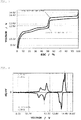
- Three of the lithium ion storage batteries 12a were connected in series as shown in FIG. 6 , thereby fabricating a first power storage pack 12, and a charge/discharge curve was measured.
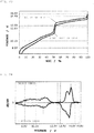
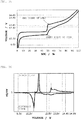
- FIG. 7 shows therein a charge/discharge curve for the first power storage pack 12 fabricated according to Example 1.
- FIG. 8 shows therein a curve (dQ/dV curve) obtained by differentiating the charge/discharge curve for the first power storage pack 12 fabricated according to Example 1 with respect to voltage.
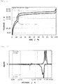
- Example 2 In the same way as in Example 1, except for the use of Li[Ni 0.05 Mn 1.95 ]O 4 as a positive electrode active material, a first power storage pack 12 was fabricated, and a charge/discharge curve was measured.
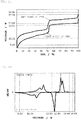
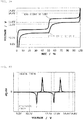
- FIG. 9 shows therein a charge/discharge curve for the first power storage pack 12, and
- FIG. 10 shows therein a dQ/dV curve therefor.
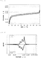
- Example 2 In the same way as in Example 1, except for the use of Li[Ni 0.15 Mn 1.85 ]O 4 as a positive electrode active material, a first power storage pack 12 was fabricated, and a charge/discharge curve was measured.
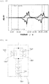
- FIG. 11 shows therein a charge/discharge curve for the first power storage pack 12, and
- FIG. 12 shows therein a dQ/dV curve therefor.
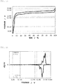
- Example 2 In the same way as in Example 1, except for the use of Li[Ni 0.35 Mn 1.65 ]O 4 as a positive electrode active material, a first power storage pack 12 was fabricated, and a charge/discharge curve was measured.
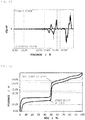
- FIG. 13 shows therein a charge/discharge curve for the first power storage pack 12, and
- FIG. 14 shows therein a dQ/dV curve therefor.
- Example 2 In the same way as in Example 1, except for the use of Li[Ni 0.45 Mn 1.55 ]O 4 as a positive electrode active material, a first power storage pack 12 was fabricated, and a charge/discharge curve was measured.
- FIG. 15 shows therein a charge/discharge curve for the first power storage pack 12, and
- FIG. 16 shows therein a dQ/dV curve therefor.
- a first power storage pack 12 was fabricated, and a charge/discharge curve was measured.
- FIG. 17 shows therein a charge/discharge curve for the first power storage pack 12, and
- FIG. 18 shows therein a dQ/dV curve therefor.
- Example 2 In the same way as in Example 1, except for the use of Li[Ni 0.50 Mn 1.50 ]O 4 as a positive electrode active material, a first power storage pack 12 was fabricated, and a charge/discharge curve was measured.
- FIG. 19 shows therein a charge/discharge curve for the first power storage pack 12, and
- FIG. 20 shows therein a dQ/dV curve therefor.
- Example 2 In the same way as in Example 1, except for the use of Li[Ni 0.25 Mn 1.75 ]O 4 as a positive electrode active material and the use of hard carbon as a negative electrode active material, a first power storage pack 12 was fabricated, and a charge/discharge curve was measured.
- FIG. 21 shows therein a charge/discharge curve for the first power storage pack 12, and
- FIG. 22 shows therein a dQ/dV curve therefor.
- Example 6 In the same way as in Example 6, except for the use of soft carbon as a negative electrode active material, a first power storage pack 12 was fabricated, and a charge/discharge curve was measured.
- FIG. 23 shows therein a charge/discharge curve for the first power storage pack 12, and
- FIG. 24 shows therein a dQ/dV curve therefor.
- FIG. 25 shows therein a charge/discharge curve for the first power storage pack 12, and
- FIG. 26 shows therein a dQ/dV curve therefor.
- FIG. 27 shows therein a charge/discharge curve for the first power storage pack 12, and
- FIG. 28 shows therein a dQ/dV curve therefor.
- Tables 1 and 2 show various types of data on Examples 1 to 9.
- the positions of the start point of the step and of the end point of the step can be easily adjusted by adjusting the value of x in the active material composition and the synthesis condition, and the ratio between the capacity on the lower SOC side than the start point of the step and the capacity on the higher SOC side than the end point of the step can be thus easily adjusted.
- the positions of the start point of the step and of the end point of the step can be adjusted by not only the value of x and the synthesis condition, but also the addition of different types of elements (for example, Li, Ti, Al, Mg, B, Cr, Co) or the substitution of the different types of elements for Ni or Mn.
- different types of elements for example, Li, Ti, Al, Mg, B, Cr, Co
- Three of the lithium ion storage battery devices 12a were connected in series as shown in FIG 6 , thereby fabricating a first power storage pack 12, and a charge/discharge curve was measured.
- FIG. 29 shows therein a charge/discharge curve for the first power storage pack 12
- FIG. 30 shows therein a dQ/dV curve therefor.
- Four of the lithium ion storage batteries 12a were connected in series as shown in FIG 33 , thereby fabricating a first power storage pack 12, and a charge/discharge curve was measured.
- FIG. 32 shows therein a charge/discharge curve for the first power storage pack 12
- FIG. 33 shows therein a dQ/dV curve therefor.
- Six of the lithium ion storage battery devices 12a were connected in series as shown in FIG 34 , thereby fabricating a first power storage pack 12, and a charge/discharge curve was measured.
- FIG. 35 shows therein a charge/discharge curve for the first power storage pack 12
- FIG. 36 shows therein a dQ/dV curve therefor.
- Tables 1 and 2 show various types of data on Examples 10 to 12.
- a lithium ion power storage module 12b1 with three of the lithium ion storage batteries 12a1 connected in series and a lithium ion power storage module 12b2 with three of the lithium ion storage batteries 12a2 connected in series were connected in parallel, thereby fabricating a first power storage pack 12, and a charge/discharge curve was measured.
- the measured charge/discharge curve was similar to the charge/discharge curve ( FIGS. 29, 30 ) according to Example 10.
- a lithium ion power storage module 12b1 composed of six of the lithium ion storage batteries 12a connected in series and a lithium ion power storage module 12b2 composed of seven of the lithium ion storage batteries 12a connected in series were connected in parallel, thereby fabricating a first power storage pack 12, and a charge/discharge curve was measured.
- FIG. 39 shows therein a charge/discharge curve for the first power storage pack 12
- FIG. 40 shows therein a dQ/dV curve therefor.
- Example 14 it is determined that the parallel connection of multiple power storage modules that differ in number of series connections makes it possible to design the first power storage pack 12 that satisfies at least one of the conditions (a), (b), and (c) and conditions (a), (d), and (e) mentioned above, in the case of using a lead storage battery pack as the second power storage pack 11.
- the capacity ratio between the two power storage modules is changed, the positions of the start point of the step and of the end point of the step can be adjusted, and the ratio between the capacity on the lower SOC side than the start point of the step and the capacity on the higher SOC side than the end point of the step can be thus also adjusted.
- FIG. 42 shows therein a charge/discharge curve for the first power storage pack 12
- FIG. 43 shows therein a dQ/dV curve therefor.
- Example 15 From the result presented in Example 15, it is determined that the parallel connection of multiple power storage modules that use different types of lithium ion storage batteries makes it possible to design the first power storage pack 12 that satisfies at least one of the conditions (a), (b), and (c) and conditions (a), (d), and (e) mentioned above, in the case of using a lead storage battery pack as the second power storage pack 11.
- changing the capacity ratio between the two power storage modules can adjust the positions of the start point of the step and of the end point of the step, and thus also adjust the ratio between the capacity on the lower SOC side than the start point of the step and the capacity on the higher SOC side than the end point of the step.
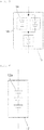
- a first power storage pack 12 was fabricated by connecting in series a lithium ion power storage module 12b1 composed of series-connected five of the lithium ion storage batteries 12a1 and a lithium ion power storage module 12b2 composed of one of the lithium ion storage batteries 12a2, and furthermore, connecting a lithium ion power storage module 12b3 composed of series-connected two of the lithium ion storage batteries 12a2 in parallel to the lithium ion power storage module 12b2, and a charge/discharge curve was measured.
- the measured charge/discharge curve was similar to the charge/discharge curve ( FIGS. 39, 40 ) according to Example 14.
- a first power storage pack 12 was fabricated by connecting in series a lithium ion power storage module 12b1 composed of series-connected two of the lithium ion storage batteries 12a1 and a lithium ion power storage module 12b2 composed of series-connected two of the lithium ion storage batteries 12a2, and furthermore, connecting series-connected three lithium ion power storage modules 12b3 in parallel to the lithium ion power storage module 12b2, and a charge/discharge curve was measured.
- the measured charge/discharge curve was similar to the charge/discharge curve ( FIGS. 44 , 45 ) according to Example 15.
- Three of the lithium ion storage batteries 12a were connected in series as shown in FIG. 6 as in Example 1, thereby fabricating a first power storage pack 12, and a charge/discharge curve was measured.
- FIG. 46 shows therein a charge/discharge curve for the first power storage pack 12, and
- FIG. 47 shows therein a dQ/dV curve therefor.
- the lithium ion storage batteries 12a were connected in series as shown in FIG. 6 as in Example 1, thereby fabricating a first power storage pack 12, and a charge/discharge curve was measured.
- FIG. 48 shows therein a charge/discharge curve for the first power storage pack 12, and
- FIG. 49 shows therein a dQ/dV curve therefor.
- Four of the lithium ion storage batteries 12a were connected in series as shown in FIG. 31 , thereby fabricating a first power storage pack 12, and a charge/discharge curve was measured.
- FIG. 50 shows therein a charge/discharge curve for the first power storage pack 12, and
- FIG. 51 shows therein a dQ/dV curve therefor.
- Six of the lithium ion storage batteries 12a were connected in series as shown in FIG. 34 , thereby fabricating a first power storage pack 12, and a charge/discharge curve was measured.
- FIG. 52 shows therein a charge/discharge curve for the first power storage pack 12
- FIG. 53 shows therein a dQ/dV curve therefor.
- FIG. 54 shows therein a charge/discharge curve for the first power storage pack 12
- FIG. 55 shows therein a dQ/dV curve therefor.
- the lithium ion storage batteries 12a were prepared.
- Six of the lithium ion storage batteries 12a were connected in series as shown in FIG. 34 , thereby fabricating a first power storage pack 12, and a charge/discharge curve was measured.
- FIG. 56 shows therein a charge/discharge curve for the first power storage pack 12
- FIG. 57 shows therein a dQ/dV curve therefor.
- FIG. 58 shows therein a charge/discharge curve for the first power storage pack 12
- FIG. 59 shows therein a dQ/dV curve therefor.
- Ninety of the lithium ion storage batteries 12a were connected in series, thereby fabricating a first power storage pack 12, and a charge/discharge curve was measured.
- FIG. 60 shows therein a charge/discharge curve for the first power storage pack 12, and
- FIG. 61 shows therein a dQ/dV curve therefor.
- FIG. 62 shows therein a charge/discharge curve for the first power storage pack 12
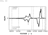
- FIG. 63 shows therein a dQ/dV curve therefor.
Landscapes
- Chemical & Material Sciences (AREA)
- Chemical Kinetics & Catalysis (AREA)
- Electrochemistry (AREA)
- General Chemical & Material Sciences (AREA)
- Engineering & Computer Science (AREA)
- Inorganic Chemistry (AREA)
- Manufacturing & Machinery (AREA)
- Materials Engineering (AREA)
- Composite Materials (AREA)
- Crystallography & Structural Chemistry (AREA)
- Power Engineering (AREA)
- Secondary Cells (AREA)
- Battery Mounting, Suspending (AREA)
- Battery Electrode And Active Subsutance (AREA)
- Connection Of Batteries Or Terminals (AREA)
Claims (8)
- Un premier bloc d'accumulateurs de puissance (12) pour connexion en parallèle avec un deuxième bloc d'accumulateurs de puissance (11) ayant une chimie de batterie différente et sans aucun convertisseur CC-CC interposé entre le premier bloc d'accumulateurs de puissance et le deuxième bloc d'accumulateurs de puissance, dans lequel :une courbe de charge/décharge du premier bloc d'accumulateurs de puissance (12) mesurée conformément au procédé décrit dans la description a un échelon passant à travers une plage de (12,5 x n) V ou plus haute et de (12,8 x n) V ou plus basse, où n est un nombre naturel de 1 ou plus et de 125 ou moins,sur un côté d'état de charge, SoC, plus bas qu'un point de départ de l'échelon de la courbe de charge/décharge du premier bloc d'accumulateurs de puissance, une tension de décharge moyenne tombe dans une plage de (9,0 x n) V ou plus haute et de (12,5 x n) V ou plus basse et/ou une tension à une pointe de crête obtenue sur une courbe dQ/dV obtenue en différenciant la courbe de décharge par rapport à la tension tombe dans une plage de (9,0 x n) ou plus haute et de (12,5 x n) V ou plus basse,sur un côté SoC plus haut qu'un point final de l'échelon de la courbe de charge/décharge du premier bloc d'accumulateurs de puissance, une tension de charge moyenne tombe dans une plage de (12,8 x n) V ou plus haute et de (14,8 x n) V ou plus basse et/ou une tension à un pointe de crête obtenue sur une courbe dQ/dV obtenue en différenciant la courbe de charge par rapport à la tension tombe dans la plage de (12,8 x n) V ou plus haute et de (14,8 x n) V ou plus basse,et dans lequel un échelon d'une courbe de charge ou de décharge se réfère à une plage dans laquelle la proportion de la quantité de changement en tension, ΔV, sur la courbe de charge/décharge à la quantité de changement en SoC, ΔSoC, est de (100 x n) mV % ou plus, lorsque le SoC est dans la plage de 5 % à 95 %, etdans lequel le point de départ d'un échelon est la tension minimale d'une courbe de décharge dans la plage d'un échelon, et la valeur correspondante du SoC à la tension minimale, etle point final de l'échelon est la tension maximale d'une courbe de charge dans la plage du même échelon, et la valeur correspondante du SoC à la tension maximale.
- Le premier bloc d'accumulateurs de puissance (12) selon la revendication 1, dans lequel le premier bloc d'accumulateurs de puissance comprend un dispositif accumulateur de puissance (12a), et le dispositif accumulateur de puissance est une batterie d'accumulateurs lithium-ion ou un batterie d'accumulateurs nickel-hydrure métallique.
- Le premier bloc d'accumulateurs de puissance (12) selon la revendication 2, dans lequel une électrode positive de la batterie d'accumulateurs lithium-ion comprend, comme un matériau d'électrode positive, au moins l'un sélectionné parmi le groupe composé de Li[NixMn(2-x)]O4 avec 0,5 ≤ x ≤ 0,45, Li[CoxMn(2-x)]O4 avec 0,1 ≤ x ≤ 1, Li[FexMn(2-x)]O4 avec 0,05 ≤ x ≤ 0,45, LiF, aMnbCocNidPO4 avec 0 ≤ a ≤ 1, 0 ≤ b ≤ 1, 0 ≤ c ≤ 1, 0 ≤ d ≤ 1, a + b + c + d = 1, et Li3V2(PO4)3.
- Le premier bloc d'accumulateurs de puissance (12) selon l'une quelconque des revendications 2 et 3, dans lequel une électrode positive de la batterie d'accumulateurs lithium-ion comprend des types multiples de matériaux actifs d'électrode positive.
- Le premier bloc d'accumulateurs de puissance (12) selon l'une quelconque des revendications 2 à 4, dans lequel une électrode négative de la batterie d'accumulateurs lithium-ion comprend des types multiples de matériaux actifs d'électrode négative.
- Le premier bloc d'accumulateurs de puissance (12) selon l'une quelconque des revendications 1 à 5, dans lequelle premier bloc d'accumulateurs de puissance a une pluralité de modules accumulateurs de puissance (12b) connectés en parallèle, les modules accumulateurs de puissance comprenant une pluralité de dispositifs accumulateurs de puissance (12a) connectés en série, etla pluralité de modules accumulateurs de puissance comprend des modules accumulateurs de puissance qui diffèrent les uns des autres en nombre d'étages de connexion.
- Le premier bloc d'accumulateurs de puissance (12) selon l'une quelconque des revendications 1 à 6, dans lequel le premier bloc d'accumulateurs de puissance comprend des types multiples de modules accumulateurs de puissance (12b) comprenant des types différents de dispositifs accumulateurs de puissance (12a).
- Le premier bloc d'accumulateurs de puissance (12) selon l'une quelconque des revendications 1 à 7, dans lequel un rapport tombe dans une plage de 10 : 90 à 90 : 10 entre une capacité sur le côté SoC plus bas que le point de départ de l'échelon de la courbe de charge/décharge du premier bloc d'accumulateurs de puissance et une capacité sur le côté SoC plus haut que le point final de l'échelon de la courbe de charge/décharge du premier bloc d'accumulateurs de puissance.
Applications Claiming Priority (2)
| Application Number | Priority Date | Filing Date | Title |
|---|---|---|---|
| JP2015190930 | 2015-09-29 | ||
| PCT/JP2016/078293 WO2017057284A1 (fr) | 2015-09-29 | 2016-09-26 | Bloc de piles rechargeables |
Publications (3)
| Publication Number | Publication Date |
|---|---|
| EP3358665A1 EP3358665A1 (fr) | 2018-08-08 |
| EP3358665A4 EP3358665A4 (fr) | 2019-05-15 |
| EP3358665B1 true EP3358665B1 (fr) | 2021-10-27 |
Family
ID=58427519
Family Applications (1)
| Application Number | Title | Priority Date | Filing Date |
|---|---|---|---|
| EP16851455.2A Active EP3358665B1 (fr) | 2015-09-29 | 2016-09-26 | Bloc de piles rechargeables |
Country Status (5)
| Country | Link |
|---|---|
| US (1) | US10720676B2 (fr) |
| EP (1) | EP3358665B1 (fr) |
| JP (1) | JP6460254B2 (fr) |
| CN (1) | CN108140868B (fr) |
| WO (1) | WO2017057284A1 (fr) |
Families Citing this family (7)
| Publication number | Priority date | Publication date | Assignee | Title |
|---|---|---|---|---|
| KR102621551B1 (ko) * | 2018-07-27 | 2024-01-05 | 삼성전자주식회사 | 음극이 갖는 전기 전도도의 속성이 다른 복수의 단위 셀을 포함하는 배터리 및 그를 포함하는 전자 장치 |
| KR102909999B1 (ko) * | 2019-07-22 | 2026-01-08 | 주식회사 엘지에너지솔루션 | 이차전지의 제조방법 |
| EP3772657B1 (fr) * | 2019-08-08 | 2023-10-04 | ABB Schweiz AG | Dispositif et procédé pour effectuer une estimation de l'état de santé |
| WO2021040306A1 (fr) * | 2019-08-23 | 2021-03-04 | 주식회사 엘지화학 | Procédé de prédiction de l'état de santé d'une batterie et bloc-batterie l'utilisant |
| US11605839B2 (en) * | 2020-02-10 | 2023-03-14 | Anduril Industries, Inc. | Battery system |
| JP7326229B2 (ja) * | 2020-07-22 | 2023-08-15 | 株式会社東芝 | 蓄電池 |
| EP4190498A1 (fr) * | 2021-12-01 | 2023-06-07 | Hilti Aktiengesellschaft | Systèmes comprenant des machines-outils et des dispositifs d'alimentation en énergie, ainsi que dispositif d'alimentation en énergie |
Family Cites Families (17)
| Publication number | Priority date | Publication date | Assignee | Title |
|---|---|---|---|---|
| JP2002141032A (ja) * | 2000-10-31 | 2002-05-17 | Nissan Motor Co Ltd | 組電池 |
| EP1451915A4 (fr) * | 2001-10-03 | 2004-12-22 | Trojan Battery Co | Systeme et procede de charge de batterie |
| JP2003308817A (ja) | 2002-04-17 | 2003-10-31 | Nissan Motor Co Ltd | 組電池 |
| US7427450B2 (en) * | 2004-12-10 | 2008-09-23 | General Motors Corporation | Hybrid fuel cell system with battery capacitor energy storage system |
| JP2007131134A (ja) * | 2005-11-10 | 2007-05-31 | Toyota Motor Corp | 車両用電源装置 |
| CN100468912C (zh) * | 2007-05-15 | 2009-03-11 | 北京恒基伟业投资发展有限公司 | 非对称蓄电池组、具有该电池组的太阳能电池及充放电法 |
| WO2008129698A1 (fr) * | 2007-04-12 | 2008-10-30 | Panasonic Corporation | Système d'alimentation et procédé de chargement d'un bloc de batterie |
| KR101237106B1 (ko) * | 2008-06-04 | 2013-02-25 | 파나소닉 주식회사 | 조립전지 |
| EP2272722B1 (fr) * | 2009-07-01 | 2015-04-08 | Denso Corporation | Appareil de source d'alimentation pour véhicule |
| CN101719557A (zh) * | 2009-12-04 | 2010-06-02 | 浙江绿源电动车有限公司 | 一种铅酸电池、锂电池混合电池包 |
| CN101908662A (zh) * | 2010-07-05 | 2010-12-08 | 河南联合新能源有限公司 | 电动汽车组合动力电池 |
| CN103828099B (zh) * | 2011-07-25 | 2018-04-20 | A123系统有限责任公司 | 掺混的阴极材料 |
| CN102544644B (zh) * | 2012-02-10 | 2015-02-25 | 中国科学院上海微系统与信息技术研究所 | 由铅酸蓄电池单体与锂离子电池单体并联组成的复合电源 |
| JP5770239B2 (ja) * | 2012-09-28 | 2015-08-26 | アマゾン電池株式会社 | バナジウムリン酸錯体二次電池 |
| CN203674347U (zh) * | 2013-11-08 | 2014-06-25 | 浙江南都电源动力股份有限公司 | 一种锂离子电池与铅酸电池混合系统 |
| CN104319425B (zh) * | 2014-08-25 | 2016-06-22 | 江苏华东锂电技术研究院有限公司 | 对锂离子电池的容量进行管理的方法 |
| WO2016080222A1 (fr) * | 2014-11-17 | 2016-05-26 | 株式会社村田製作所 | Batterie embarquée, et dispositif d'alimentation électrique embarqué |
-
2016
- 2016-09-26 EP EP16851455.2A patent/EP3358665B1/fr active Active
- 2016-09-26 JP JP2017543264A patent/JP6460254B2/ja active Active
- 2016-09-26 WO PCT/JP2016/078293 patent/WO2017057284A1/fr not_active Ceased
- 2016-09-26 CN CN201680056629.5A patent/CN108140868B/zh active Active
-
2018
- 2018-03-19 US US15/924,994 patent/US10720676B2/en active Active
Non-Patent Citations (1)
| Title |
|---|
| None * |
Also Published As
| Publication number | Publication date |
|---|---|
| US10720676B2 (en) | 2020-07-21 |
| EP3358665A1 (fr) | 2018-08-08 |
| EP3358665A4 (fr) | 2019-05-15 |
| JPWO2017057284A1 (ja) | 2018-05-24 |
| WO2017057284A1 (fr) | 2017-04-06 |
| JP6460254B2 (ja) | 2019-01-30 |
| CN108140868A (zh) | 2018-06-08 |
| US20180212213A1 (en) | 2018-07-26 |
| CN108140868B (zh) | 2021-03-23 |
Similar Documents
| Publication | Publication Date | Title |
|---|---|---|
| US10780793B2 (en) | Power storage system, transfer mechanism, transport mechanism, vehicle, and automobile | |
| EP3358665B1 (fr) | Bloc de piles rechargeables | |
| EP3358706B1 (fr) | Système de stabilisation d'alimentation électrique | |
| KR100903244B1 (ko) | 조전지 시스템, 조전지의 충전 방법 및 충전식 청소기 | |
| US20110206950A1 (en) | Energy storage unit, particularly accumulator | |
| US20140186659A1 (en) | Hybrid battery system for electric and hybrid electric vehicles | |
| KR101568110B1 (ko) | 2차 전지의 충전 제어 방법 및 충전 제어 장치 | |
| KR20080073220A (ko) | 전지 유닛 | |
| KR20060051554A (ko) | 축전 시스템, 회생 축전 시스템 및 자동차 | |
| JP2015519005A (ja) | 出力特性が向上した混合正極活物質、及びこれを含むリチウム二次電池 | |
| CN101090161A (zh) | 蓄电池系统、车载电源系统、车辆和蓄电池系统的充电方法 | |
| US20170166078A1 (en) | Battery charge equalization system | |
| US20100230191A1 (en) | Electrochemical cell with a non-graphitizable carbon electrode and energy storage assembly | |
| EP2073302A1 (fr) | Dispositif de commande de décharge | |
| US20190389407A1 (en) | Assembled battery, vehicle, and method of manufacturing assembled battery | |
| EP4228043A1 (fr) | Groupe de batteries, bloc-batterie, appareil électrique, procédé de fabrication et dispositif de fabrication de groupe de batteries, et procédé de commande de groupe de batteries | |
| US11909040B2 (en) | Electrode assembly | |
| JP2022124124A (ja) | 全固体リチウム二次電池システム | |
| WO2016080222A1 (fr) | Batterie embarquée, et dispositif d'alimentation électrique embarqué | |
| EP4528847A1 (fr) | Ensemble électrode, batterie secondaire et appareil électrique | |
| KR20120113008A (ko) | 직렬방식 phev용 리튬이차전지 양극재 및 이를 포함하는 리튬이차전지 | |
| KR20260047882A (ko) | 배터리셀 |
Legal Events
| Date | Code | Title | Description |
|---|---|---|---|
| STAA | Information on the status of an ep patent application or granted ep patent |
Free format text: STATUS: THE INTERNATIONAL PUBLICATION HAS BEEN MADE |
|
| PUAI | Public reference made under article 153(3) epc to a published international application that has entered the european phase |
Free format text: ORIGINAL CODE: 0009012 |
|
| STAA | Information on the status of an ep patent application or granted ep patent |
Free format text: STATUS: REQUEST FOR EXAMINATION WAS MADE |
|
| 17P | Request for examination filed |
Effective date: 20180313 |
|
| AK | Designated contracting states |
Kind code of ref document: A1 Designated state(s): AL AT BE BG CH CY CZ DE DK EE ES FI FR GB GR HR HU IE IS IT LI LT LU LV MC MK MT NL NO PL PT RO RS SE SI SK SM TR |
|
| AX | Request for extension of the european patent |
Extension state: BA ME |
|
| DAV | Request for validation of the european patent (deleted) | ||
| DAX | Request for extension of the european patent (deleted) | ||
| A4 | Supplementary search report drawn up and despatched |
Effective date: 20190417 |
|
| RIC1 | Information provided on ipc code assigned before grant |
Ipc: H01M 10/42 20060101ALI20190411BHEP Ipc: H01M 10/44 20060101ALI20190411BHEP Ipc: H01M 10/0525 20100101ALI20190411BHEP Ipc: H01M 10/46 20060101ALI20190411BHEP Ipc: H01M 4/131 20100101ALI20190411BHEP Ipc: H01M 10/058 20100101ALI20190411BHEP Ipc: H01M 10/04 20060101AFI20190411BHEP Ipc: H01M 10/052 20100101ALI20190411BHEP Ipc: H02J 7/00 20060101ALI20190411BHEP Ipc: H01M 4/58 20100101ALI20190411BHEP Ipc: H01M 10/30 20060101ALI20190411BHEP Ipc: H01M 4/525 20100101ALI20190411BHEP Ipc: H01M 2/10 20060101ALI20190411BHEP Ipc: H01M 16/00 20060101ALI20190411BHEP Ipc: H01M 4/505 20100101ALI20190411BHEP Ipc: H01M 4/36 20060101ALI20190411BHEP |
|
| STAA | Information on the status of an ep patent application or granted ep patent |
Free format text: STATUS: EXAMINATION IS IN PROGRESS |
|
| 17Q | First examination report despatched |
Effective date: 20200129 |
|
| REG | Reference to a national code |
Ref country code: DE Ref legal event code: R079 Ref document number: 602016065555 Country of ref document: DE Free format text: PREVIOUS MAIN CLASS: H01M0010040000 Ipc: H01M0050204000 |
|
| RIC1 | Information provided on ipc code assigned before grant |
Ipc: H01M 50/204 20210101AFI20210211BHEP |
|
| GRAP | Despatch of communication of intention to grant a patent |
Free format text: ORIGINAL CODE: EPIDOSNIGR1 |
|
| STAA | Information on the status of an ep patent application or granted ep patent |
Free format text: STATUS: GRANT OF PATENT IS INTENDED |
|
| INTG | Intention to grant announced |
Effective date: 20210416 |
|
| GRAS | Grant fee paid |
Free format text: ORIGINAL CODE: EPIDOSNIGR3 |
|
| GRAA | (expected) grant |
Free format text: ORIGINAL CODE: 0009210 |
|
| STAA | Information on the status of an ep patent application or granted ep patent |
Free format text: STATUS: THE PATENT HAS BEEN GRANTED |
|
| AK | Designated contracting states |
Kind code of ref document: B1 Designated state(s): AL AT BE BG CH CY CZ DE DK EE ES FI FR GB GR HR HU IE IS IT LI LT LU LV MC MK MT NL NO PL PT RO RS SE SI SK SM TR |
|
| REG | Reference to a national code |
Ref country code: GB Ref legal event code: FG4D |
|
| REG | Reference to a national code |
Ref country code: CH Ref legal event code: EP |
|
| REG | Reference to a national code |
Ref country code: AT Ref legal event code: REF Ref document number: 1442656 Country of ref document: AT Kind code of ref document: T Effective date: 20211115 |
|
| REG | Reference to a national code |
Ref country code: DE Ref legal event code: R096 Ref document number: 602016065555 Country of ref document: DE |
|
| REG | Reference to a national code |
Ref country code: IE Ref legal event code: FG4D |
|
| REG | Reference to a national code |
Ref country code: LT Ref legal event code: MG9D |
|
| REG | Reference to a national code |
Ref country code: NL Ref legal event code: MP Effective date: 20211027 |
|
| REG | Reference to a national code |
Ref country code: AT Ref legal event code: MK05 Ref document number: 1442656 Country of ref document: AT Kind code of ref document: T Effective date: 20211027 |
|
| PG25 | Lapsed in a contracting state [announced via postgrant information from national office to epo] |
Ref country code: RS Free format text: LAPSE BECAUSE OF FAILURE TO SUBMIT A TRANSLATION OF THE DESCRIPTION OR TO PAY THE FEE WITHIN THE PRESCRIBED TIME-LIMIT Effective date: 20211027 Ref country code: LT Free format text: LAPSE BECAUSE OF FAILURE TO SUBMIT A TRANSLATION OF THE DESCRIPTION OR TO PAY THE FEE WITHIN THE PRESCRIBED TIME-LIMIT Effective date: 20211027 Ref country code: FI Free format text: LAPSE BECAUSE OF FAILURE TO SUBMIT A TRANSLATION OF THE DESCRIPTION OR TO PAY THE FEE WITHIN THE PRESCRIBED TIME-LIMIT Effective date: 20211027 Ref country code: BG Free format text: LAPSE BECAUSE OF FAILURE TO SUBMIT A TRANSLATION OF THE DESCRIPTION OR TO PAY THE FEE WITHIN THE PRESCRIBED TIME-LIMIT Effective date: 20220127 Ref country code: AT Free format text: LAPSE BECAUSE OF FAILURE TO SUBMIT A TRANSLATION OF THE DESCRIPTION OR TO PAY THE FEE WITHIN THE PRESCRIBED TIME-LIMIT Effective date: 20211027 |
|
| PG25 | Lapsed in a contracting state [announced via postgrant information from national office to epo] |
Ref country code: IS Free format text: LAPSE BECAUSE OF FAILURE TO SUBMIT A TRANSLATION OF THE DESCRIPTION OR TO PAY THE FEE WITHIN THE PRESCRIBED TIME-LIMIT Effective date: 20220227 Ref country code: SE Free format text: LAPSE BECAUSE OF FAILURE TO SUBMIT A TRANSLATION OF THE DESCRIPTION OR TO PAY THE FEE WITHIN THE PRESCRIBED TIME-LIMIT Effective date: 20211027 Ref country code: PT Free format text: LAPSE BECAUSE OF FAILURE TO SUBMIT A TRANSLATION OF THE DESCRIPTION OR TO PAY THE FEE WITHIN THE PRESCRIBED TIME-LIMIT Effective date: 20220228 Ref country code: PL Free format text: LAPSE BECAUSE OF FAILURE TO SUBMIT A TRANSLATION OF THE DESCRIPTION OR TO PAY THE FEE WITHIN THE PRESCRIBED TIME-LIMIT Effective date: 20211027 Ref country code: NO Free format text: LAPSE BECAUSE OF FAILURE TO SUBMIT A TRANSLATION OF THE DESCRIPTION OR TO PAY THE FEE WITHIN THE PRESCRIBED TIME-LIMIT Effective date: 20220127 Ref country code: NL Free format text: LAPSE BECAUSE OF FAILURE TO SUBMIT A TRANSLATION OF THE DESCRIPTION OR TO PAY THE FEE WITHIN THE PRESCRIBED TIME-LIMIT Effective date: 20211027 Ref country code: LV Free format text: LAPSE BECAUSE OF FAILURE TO SUBMIT A TRANSLATION OF THE DESCRIPTION OR TO PAY THE FEE WITHIN THE PRESCRIBED TIME-LIMIT Effective date: 20211027 Ref country code: HR Free format text: LAPSE BECAUSE OF FAILURE TO SUBMIT A TRANSLATION OF THE DESCRIPTION OR TO PAY THE FEE WITHIN THE PRESCRIBED TIME-LIMIT Effective date: 20211027 Ref country code: GR Free format text: LAPSE BECAUSE OF FAILURE TO SUBMIT A TRANSLATION OF THE DESCRIPTION OR TO PAY THE FEE WITHIN THE PRESCRIBED TIME-LIMIT Effective date: 20220128 Ref country code: ES Free format text: LAPSE BECAUSE OF FAILURE TO SUBMIT A TRANSLATION OF THE DESCRIPTION OR TO PAY THE FEE WITHIN THE PRESCRIBED TIME-LIMIT Effective date: 20211027 |
|
| REG | Reference to a national code |
Ref country code: DE Ref legal event code: R097 Ref document number: 602016065555 Country of ref document: DE |
|
| PG25 | Lapsed in a contracting state [announced via postgrant information from national office to epo] |
Ref country code: SM Free format text: LAPSE BECAUSE OF FAILURE TO SUBMIT A TRANSLATION OF THE DESCRIPTION OR TO PAY THE FEE WITHIN THE PRESCRIBED TIME-LIMIT Effective date: 20211027 Ref country code: SK Free format text: LAPSE BECAUSE OF FAILURE TO SUBMIT A TRANSLATION OF THE DESCRIPTION OR TO PAY THE FEE WITHIN THE PRESCRIBED TIME-LIMIT Effective date: 20211027 Ref country code: RO Free format text: LAPSE BECAUSE OF FAILURE TO SUBMIT A TRANSLATION OF THE DESCRIPTION OR TO PAY THE FEE WITHIN THE PRESCRIBED TIME-LIMIT Effective date: 20211027 Ref country code: EE Free format text: LAPSE BECAUSE OF FAILURE TO SUBMIT A TRANSLATION OF THE DESCRIPTION OR TO PAY THE FEE WITHIN THE PRESCRIBED TIME-LIMIT Effective date: 20211027 Ref country code: DK Free format text: LAPSE BECAUSE OF FAILURE TO SUBMIT A TRANSLATION OF THE DESCRIPTION OR TO PAY THE FEE WITHIN THE PRESCRIBED TIME-LIMIT Effective date: 20211027 Ref country code: CZ Free format text: LAPSE BECAUSE OF FAILURE TO SUBMIT A TRANSLATION OF THE DESCRIPTION OR TO PAY THE FEE WITHIN THE PRESCRIBED TIME-LIMIT Effective date: 20211027 |
|
| PLBE | No opposition filed within time limit |
Free format text: ORIGINAL CODE: 0009261 |
|
| STAA | Information on the status of an ep patent application or granted ep patent |
Free format text: STATUS: NO OPPOSITION FILED WITHIN TIME LIMIT |
|
| 26N | No opposition filed |
Effective date: 20220728 |
|
| PG25 | Lapsed in a contracting state [announced via postgrant information from national office to epo] |
Ref country code: AL Free format text: LAPSE BECAUSE OF FAILURE TO SUBMIT A TRANSLATION OF THE DESCRIPTION OR TO PAY THE FEE WITHIN THE PRESCRIBED TIME-LIMIT Effective date: 20211027 |
|
| PG25 | Lapsed in a contracting state [announced via postgrant information from national office to epo] |
Ref country code: SI Free format text: LAPSE BECAUSE OF FAILURE TO SUBMIT A TRANSLATION OF THE DESCRIPTION OR TO PAY THE FEE WITHIN THE PRESCRIBED TIME-LIMIT Effective date: 20211027 |
|
| PG25 | Lapsed in a contracting state [announced via postgrant information from national office to epo] |
Ref country code: MC Free format text: LAPSE BECAUSE OF FAILURE TO SUBMIT A TRANSLATION OF THE DESCRIPTION OR TO PAY THE FEE WITHIN THE PRESCRIBED TIME-LIMIT Effective date: 20211027 |
|
| REG | Reference to a national code |
Ref country code: CH Ref legal event code: PL |
|
| GBPC | Gb: european patent ceased through non-payment of renewal fee |
Effective date: 20220926 |
|
| REG | Reference to a national code |
Ref country code: BE Ref legal event code: MM Effective date: 20220930 |
|
| PG25 | Lapsed in a contracting state [announced via postgrant information from national office to epo] |
Ref country code: IT Free format text: LAPSE BECAUSE OF FAILURE TO SUBMIT A TRANSLATION OF THE DESCRIPTION OR TO PAY THE FEE WITHIN THE PRESCRIBED TIME-LIMIT Effective date: 20211027 |
|
| PG25 | Lapsed in a contracting state [announced via postgrant information from national office to epo] |
Ref country code: LU Free format text: LAPSE BECAUSE OF NON-PAYMENT OF DUE FEES Effective date: 20220926 |
|
| PG25 | Lapsed in a contracting state [announced via postgrant information from national office to epo] |
Ref country code: LI Free format text: LAPSE BECAUSE OF NON-PAYMENT OF DUE FEES Effective date: 20220930 Ref country code: IE Free format text: LAPSE BECAUSE OF NON-PAYMENT OF DUE FEES Effective date: 20220926 Ref country code: FR Free format text: LAPSE BECAUSE OF NON-PAYMENT OF DUE FEES Effective date: 20220930 Ref country code: CH Free format text: LAPSE BECAUSE OF NON-PAYMENT OF DUE FEES Effective date: 20220930 |
|
| PG25 | Lapsed in a contracting state [announced via postgrant information from national office to epo] |
Ref country code: BE Free format text: LAPSE BECAUSE OF NON-PAYMENT OF DUE FEES Effective date: 20220930 |
|
| PG25 | Lapsed in a contracting state [announced via postgrant information from national office to epo] |
Ref country code: GB Free format text: LAPSE BECAUSE OF NON-PAYMENT OF DUE FEES Effective date: 20220926 |
|
| PG25 | Lapsed in a contracting state [announced via postgrant information from national office to epo] |
Ref country code: HU Free format text: LAPSE BECAUSE OF FAILURE TO SUBMIT A TRANSLATION OF THE DESCRIPTION OR TO PAY THE FEE WITHIN THE PRESCRIBED TIME-LIMIT; INVALID AB INITIO Effective date: 20160926 |
|
| PG25 | Lapsed in a contracting state [announced via postgrant information from national office to epo] |
Ref country code: CY Free format text: LAPSE BECAUSE OF FAILURE TO SUBMIT A TRANSLATION OF THE DESCRIPTION OR TO PAY THE FEE WITHIN THE PRESCRIBED TIME-LIMIT Effective date: 20211027 |
|
| PG25 | Lapsed in a contracting state [announced via postgrant information from national office to epo] |
Ref country code: MK Free format text: LAPSE BECAUSE OF FAILURE TO SUBMIT A TRANSLATION OF THE DESCRIPTION OR TO PAY THE FEE WITHIN THE PRESCRIBED TIME-LIMIT Effective date: 20211027 |
|
| PG25 | Lapsed in a contracting state [announced via postgrant information from national office to epo] |
Ref country code: TR Free format text: LAPSE BECAUSE OF FAILURE TO SUBMIT A TRANSLATION OF THE DESCRIPTION OR TO PAY THE FEE WITHIN THE PRESCRIBED TIME-LIMIT Effective date: 20211027 |
|
| PG25 | Lapsed in a contracting state [announced via postgrant information from national office to epo] |
Ref country code: MT Free format text: LAPSE BECAUSE OF FAILURE TO SUBMIT A TRANSLATION OF THE DESCRIPTION OR TO PAY THE FEE WITHIN THE PRESCRIBED TIME-LIMIT Effective date: 20211027 |
|
| PGFP | Annual fee paid to national office [announced via postgrant information from national office to epo] |
Ref country code: DE Payment date: 20250919 Year of fee payment: 10 |