EP3358701A2 - Circuit de charge pourvu de convertisseur continu-continu et procédé de charge pour un système d'accumulation d'énergie électrique - Google Patents
Circuit de charge pourvu de convertisseur continu-continu et procédé de charge pour un système d'accumulation d'énergie électrique Download PDFInfo
- Publication number
- EP3358701A2 EP3358701A2 EP18153126.0A EP18153126A EP3358701A2 EP 3358701 A2 EP3358701 A2 EP 3358701A2 EP 18153126 A EP18153126 A EP 18153126A EP 3358701 A2 EP3358701 A2 EP 3358701A2
- Authority
- EP
- European Patent Office
- Prior art keywords
- energy storage
- switch
- output
- electrical energy
- terminal
- Prior art date
- Legal status (The legal status is an assumption and is not a legal conclusion. Google has not performed a legal analysis and makes no representation as to the accuracy of the status listed.)
- Granted
Links
Images
Classifications
-
- H—ELECTRICITY
- H02—GENERATION; CONVERSION OR DISTRIBUTION OF ELECTRIC POWER
- H02J—ELECTRIC POWER NETWORKS; CIRCUIT ARRANGEMENTS OR SYSTEMS FOR SUPPLYING OR DISTRIBUTING ELECTRIC POWER; SYSTEMS FOR STORING ELECTRIC ENERGY
- H02J7/00—Circuit arrangements for charging or discharging batteries or for supplying loads from batteries
- H02J7/50—Circuit arrangements for charging or discharging batteries or for supplying loads from batteries acting upon multiple batteries simultaneously or sequentially
- H02J7/52—Circuit arrangements for charging or discharging batteries or for supplying loads from batteries acting upon multiple batteries simultaneously or sequentially for charge balancing, e.g. equalisation of charge between batteries
- H02J7/54—Passive balancing, e.g. using resistors or parallel MOSFETs
-
- H—ELECTRICITY
- H02—GENERATION; CONVERSION OR DISTRIBUTION OF ELECTRIC POWER
- H02J—ELECTRIC POWER NETWORKS; CIRCUIT ARRANGEMENTS OR SYSTEMS FOR SUPPLYING OR DISTRIBUTING ELECTRIC POWER; SYSTEMS FOR STORING ELECTRIC ENERGY
- H02J7/00—Circuit arrangements for charging or discharging batteries or for supplying loads from batteries
- H02J7/50—Circuit arrangements for charging or discharging batteries or for supplying loads from batteries acting upon multiple batteries simultaneously or sequentially
- H02J7/575—Parallel/serial switching of connection of batteries to charge or load circuit
-
- B—PERFORMING OPERATIONS; TRANSPORTING
- B60—VEHICLES IN GENERAL
- B60L—PROPULSION OF ELECTRICALLY-PROPELLED VEHICLES; SUPPLYING ELECTRIC POWER FOR AUXILIARY EQUIPMENT OF ELECTRICALLY-PROPELLED VEHICLES; ELECTRODYNAMIC BRAKE SYSTEMS FOR VEHICLES IN GENERAL; MAGNETIC SUSPENSION OR LEVITATION FOR VEHICLES; MONITORING OPERATING VARIABLES OF ELECTRICALLY-PROPELLED VEHICLES; ELECTRIC SAFETY DEVICES FOR ELECTRICALLY-PROPELLED VEHICLES
- B60L53/00—Methods of charging batteries, specially adapted for electric vehicles; Charging stations or on-board charging equipment therefor; Exchange of energy storage elements in electric vehicles
- B60L53/20—Methods of charging batteries, specially adapted for electric vehicles; Charging stations or on-board charging equipment therefor; Exchange of energy storage elements in electric vehicles characterised by converters located in the vehicle
-
- Y—GENERAL TAGGING OF NEW TECHNOLOGICAL DEVELOPMENTS; GENERAL TAGGING OF CROSS-SECTIONAL TECHNOLOGIES SPANNING OVER SEVERAL SECTIONS OF THE IPC; TECHNICAL SUBJECTS COVERED BY FORMER USPC CROSS-REFERENCE ART COLLECTIONS [XRACs] AND DIGESTS
- Y02—TECHNOLOGIES OR APPLICATIONS FOR MITIGATION OR ADAPTATION AGAINST CLIMATE CHANGE
- Y02T—CLIMATE CHANGE MITIGATION TECHNOLOGIES RELATED TO TRANSPORTATION
- Y02T10/00—Road transport of goods or passengers
- Y02T10/60—Other road transportation technologies with climate change mitigation effect
- Y02T10/70—Energy storage systems for electromobility, e.g. batteries
-
- Y—GENERAL TAGGING OF NEW TECHNOLOGICAL DEVELOPMENTS; GENERAL TAGGING OF CROSS-SECTIONAL TECHNOLOGIES SPANNING OVER SEVERAL SECTIONS OF THE IPC; TECHNICAL SUBJECTS COVERED BY FORMER USPC CROSS-REFERENCE ART COLLECTIONS [XRACs] AND DIGESTS
- Y02—TECHNOLOGIES OR APPLICATIONS FOR MITIGATION OR ADAPTATION AGAINST CLIMATE CHANGE
- Y02T—CLIMATE CHANGE MITIGATION TECHNOLOGIES RELATED TO TRANSPORTATION
- Y02T10/00—Road transport of goods or passengers
- Y02T10/60—Other road transportation technologies with climate change mitigation effect
- Y02T10/7072—Electromobility specific charging systems or methods for batteries, ultracapacitors, supercapacitors or double-layer capacitors
-
- Y—GENERAL TAGGING OF NEW TECHNOLOGICAL DEVELOPMENTS; GENERAL TAGGING OF CROSS-SECTIONAL TECHNOLOGIES SPANNING OVER SEVERAL SECTIONS OF THE IPC; TECHNICAL SUBJECTS COVERED BY FORMER USPC CROSS-REFERENCE ART COLLECTIONS [XRACs] AND DIGESTS
- Y02—TECHNOLOGIES OR APPLICATIONS FOR MITIGATION OR ADAPTATION AGAINST CLIMATE CHANGE
- Y02T—CLIMATE CHANGE MITIGATION TECHNOLOGIES RELATED TO TRANSPORTATION
- Y02T90/00—Enabling technologies or technologies with a potential or indirect contribution to GHG emissions mitigation
- Y02T90/10—Technologies relating to charging of electric vehicles
- Y02T90/14—Plug-in electric vehicles
Definitions
- the present disclosure is based on a charging circuit with a DC-DC converter for an electrical energy storage system, a charging method for charging operation of an electrical energy storage system and an electrical energy storage system according to the preamble of the independent claims.
- a normal operating voltage of the vehicle drivetrain is currently limited to values of typically 300V to 450V for purely electrically powered vehicles.
- Standard-compliant charging plugs are typically certified for rated currents up to 200 A, with DC charging voltage typically between 200 V to 850 V.
- communication between energy storage system and charging device charging device side can be done within certain limits, a continuous control of charging voltage and charging current.
- a charging circuit for an electrical energy storage system a charging method for charging operation of an electrical energy storage system and an electrical energy storage system provided with the characterizing features of the independent claims.
- the charging circuit for an electrical energy storage system comprising n electrical energy storage units each having a first pole and a second pole, where n> 1, at least a first input and a second input for electrical connection to a power source, at least one first output and a second output for electrical connection to an electrical component, at least n first pole terminals and n second pole terminals, wherein an i-th first pole terminal to the first pole of the ith electrical energy storage unit and an i-th second pole terminal to the second pole of i -th electrical energy storage unit electrically conductively connected.
- the charging circuit has at least n first switches, wherein a first terminal of the ith first switch is electrically conductively connected to the ith first pole terminal of the ith electrical energy storage unit.
- the charging circuit has a DC-DC converter and furthermore the first output is electrically conductively connected to the second terminal of the first switch, the second output is electrically conductively connected to the second terminal of the first second switch, the first input is connected to the first terminal of the n-th first switch electrically connected and the second input to the first terminal of the first second switch electrically conductively connected.
- the first switches, the second switches and the third switches are furthermore connected in such a way that an at least twice as high voltage level is applied between the first input and the second input in the charging mode by means of a power source connected to the first input and the second input Comparison with the voltage level between the first output and the second output.
- a first electrical input of the DC-DC converter is electrically conductively connected to the first input of the charging circuit and a second input of the DC-DC converter electrically connected to the second input of the charging circuit.
- a first electrical output of the DC-DC converter is electrically conductively connected to the first output of the charging circuit and a second electrical output of the DC-DC converter electrically connected to the second output of the charging circuit.
- the DC-DC converter no different load on the energy storage units for powering the electrical components, all energy storage units are evenly charged.
- the increased voltage level in the charging mode can vary slightly.
- the power source is a DC power source, allowing its connection to the first input and the second input of the charging circuit.
- the switches are designed, for example, as semiconductor switches, for example as MOSFETs or IGBTs, but also as electromechanical relays or contactors, wherein the first switching losses are reduced and the latter represents proven, reliable technology.
- the charging circuit is designed so that even when the first first switch and / or opened first second switch, the first electrical output of the DC-DC converter is electrically connected to the first output of the charging circuit and the second electrical Output of the DC-DC converter is electrically connected to the second output of the charging circuit.
- the DC-DC converter can for example also be integrated within an on-board charger already present in a vehicle or be present as an independent component.
- the electrical voltage level between the first electrical output of the DC-DC converter and the second electrical output of the DC-DC converter is substantially equal to the voltage level between the first output of the charging circuit and the second output of the charging circuit and further equalizes the voltage level between the first electrical input of the DC-DC converter and the second electrical input of the DC-DC converter substantially the voltage level between the first input of the charging circuit and the second input of the charging circuit. This ensures that the DC-DC converter can supply the electrical components connected to the outputs of the charging circuit with electrical energy, wherein it can be simultaneously supplied with electrical energy by the energy source.
- the charging circuit is configured such that the second terminal of the ith second switch is electrically conductively connected to the second output and the second terminal of the ith first switch is electrically conductively connected to the first output.
- the charging circuit is configured such that the second terminal of the ith second switch is electrically conductively connected to the second output and the second terminal of the ith first switch is electrically conductively connected to the first output.
- the charging circuit comprises at least n-1 fourth switch, wherein in the electrical connection between the second terminal of the k th third switch to the second pole terminal of the k + 1-th electrical energy storage unit, the k-th fourth switch is inserted and the second terminal of the k th third switch with a first terminal of the k th fourth switch is electrically connected and a second terminal of the k th fourth switch with the second pole terminal of the k + 1-th electrical energy storage unit is electrically connected.
- the electrical line producing the series connection can be disconnected from the potential of the electrical energy storage units by all poles, which is a requirement in the automotive field.
- the charging circuit comprises at least one fifth switch for each two-element subset of the n-elemental quantity of the electrical energy storage units that does not consist of adjacent elements.
- a first terminal of the respective fifth switch is electrically conductively connected to the first pole terminal of the respective first electrical energy storage unit and a second terminal of the respective fifth switch to the second pole terminal of the respective second electrical energy storage unit.
- the charging circuit expediently comprises at least the fifth switch and at least one sixth switch for each two-element subset of the n-elemental quantity of the electrical energy storage units that does not consist of adjacent elements.
- the first terminal of the respective fifth switch is electrically conductively connected to the first pole terminal of the respective first electrical energy storage unit and the second terminal of the respective fifth switch to a first terminal of the respective sixth switch.
- a second terminal of the respective sixth switch is electrically conductively connected to the second pole terminal of the respective second electrical energy storage unit.
- an inductive component for example a coil
- at least one first switch and / or at least one second switch is electrically connected in series with at least one first switch and / or at least one second switch.
- the invention further relates to a charging method for charging an electrical energy storage system, wherein the electrical energy storage system has at least n electrical energy storage units and at least one charging circuit according to the invention, where n> 1.
- the method comprises selecting at least two of the n electrical energy storage units to be charged during charging by means of an energy source connected to the first input and the second input, and deciding whether one to the first output and the second Output connected electrical component during charging with electrical energy to be supplied by the DC-DC converter.
- the first switch and the second switch of the electrical energy storage units to be charged are opened.
- closing of those third switches which connect the electrical energy storage units to be charged in series takes place.
- the power supply is started by means of an energy source connected to the first input and the second input, wherein in a positive decision, the electrical component connected to the first output and the second output is supplied with electrical energy during charging by the DC-DC converter.
- the subject matter of the disclosure is an electrical energy storage system having at least two electrical energy storage units, wherein the electrical energy storage system comprises one of the charging circuits disclosed above.
- the electrical energy storage system comprises one of the charging circuits disclosed above.
- the subject matter of the disclosure is a use of one of the disclosed charging circuits in electrically driven vehicles including hybrid vehicles, in stationary energy storage systems and in electrically operated hand tools.
- electrically driven vehicles including hybrid vehicles
- stationary energy storage systems for example, stationary energy storage systems
- electrically operated hand tools for example, for a Akkubohrmaschine
- the possibility opened to significantly reduce the charging time which makes obsolete, for example, the need for a very large energy storage or more spare energy storage.
- An electrical energy storage unit may in particular be understood as meaning an electrochemical battery cell and / or a battery module having at least one electrochemical battery cell and / or a battery pack having at least one battery module.
- the electric energy storage unit may be a lithium-based battery cell or a lithium-based battery module or a lithium-based battery pack.
- the electrical energy storage unit may be a lithium-ion battery cell or a lithium-ion battery module or a lithium-ion battery pack.
- the battery cell may be of the type lithium polymer accumulator, nickel metal hydride accumulator, lead acid accumulator, lithium air accumulator or lithium sulfur accumulator or more generally an accumulator of any electrochemical composition.
- a capacitor is possible as an electrical energy storage unit.
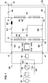
- FIG. 1 shows a charging circuit 200 according to the invention for a vehicle with two electrical energy storage units R1 and R2 according to a first embodiment.
- electrical components which can remain unchanged when using the charging circuit 200 according to the invention.
- these are an electric motor 107, an inverter 106, a DC / DC converter 104 for the 12 V electrical system and the vehicle electrical system battery 105, an intermediate circuit with DC link capacity 103 and an air-conditioning compressor 102. All electrical components, via the Consequently, the first output A1 and the second output A2 are connected to the charging circuit 200, so that they can continue to be used unchanged.
- the electrical energy storage units R1 and R2 are connected to the charging circuit 200 according to the invention within the battery 100 via the two first pole terminals P1 and the two second pole terminals P2.
- the electrical energy storage units R1 and R2 consist of several individual battery cells 101.
- a first first switch S11 and a first second switch S21 are used in particular to an electrical connection of the first electrical energy storage unit R1 to the first output A1 and to allow the second output A2.
- a second first switch S12 and a second second switch S22 serve, in particular, to enable an electrical connection of the second electrical energy storage unit R2 to the first output A1 or the second output A2.
- a first third switch S31 is used to interconnect the electrical energy storage units R1 and R2 in series with one another during charging operation.
- An energy supply is effected by an energy source connected to the first input E1 and the second input E2. Via two switches 108, the first input E1 and the second input E2 can be disconnected from the energy storage units. This ensures that the inputs can be de-energized when not charging.
- the charging circuit 200 has a DC-DC converter DC with a first input DCE1 and a second input DCE2 and a first output DCA1 and a second output DCA2.
- the first input DCE1 of the DC-DC converter DC is connected to the first input E1 of the charging circuit 200 via the first switch 108.
- the second input DCE2 of the DC-DC converter DC is connected via the second switch 108 to the second input E2 of the charging circuit 200.
- the first output DCA1 of the DC-DC converter DC is connected to the first output A1 of the charging circuit 200.
- the second output DCA2 of the DC-DC converter DC is connected to the second output A2 of the charging circuit 200.
- the DC-DC converter DC can thus convert the voltage applied between the inputs E1 and E2 to a voltage suitable for the aforementioned electrical components and thus supply them with electrical energy even when the switches S11, S21 are open. This requires that the electrical energy storage units R1 and R2 are charged to the same extent. Possible compensation processes are therefore not necessary.
- the double voltage in the charging mode between the first input E1 and the second input E2, the double voltage, it can therefore be transmitted at the same power twice the amount of energy. Care must be taken when making the series connection that first the second first switch S12 and the second second switch S22 are opened before the first third switch S31 is closed in order to avoid a short circuit.
- the first first switch S11 and the first second switch S21 are in the open state for the same charge of the electrical energy storage units R1, R2, the supply of the connected electrical components taking place via the DC-DC converter DC.
- the supply of the connected electrical components 102 to 107 makes sense to supply during the charging process, for example, the cooling system of the battery 100 and connected 12V consumers.
- the switch position of said switches changes as follows: S11 S12 S21 S22 S31 108 Switch position in non-charging mode closed closed closed closed open open
- the second first switch S12 can be operated in a clocked manner for a certain time, for example a few minutes, for equalizing the current flow.
- the equalizing current will be relatively low due to the same charge, it may nevertheless occur due to capacitance deviations in the battery cells 101.
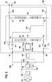
- FIG. 2 shows a charging circuit 300 according to the invention for a vehicle with two electrical energy storage units R1 and R2 according to a second embodiment.
- electrical components connected via the first output A1 and the second output A2 during or after the charging process can be supplied both by the first electrical energy storage unit R1 and by the second electrical energy storage unit R2.
- the first switches S11 and S12 are each electrically connected to their second terminals to the first output A1 and the second switches S21 and S22 each having its second terminals to the second output A2. This makes it possible to alternately connect or disconnect the electrical components connected via the first and second outputs A1 and A2 to the first electrical energy storage unit R1 or the second electrical energy storage unit R2.
- the charging circuit 300 has a DC-DC converter DC with a first input DCE1 and a second input DCE2 and a first output DCA1 and a second output DCA2.
- the first input DCE1 of the DC-DC converter DC is connected to the first input E1 of the charging circuit 300 via the first switch 108.
- the second input DCE2 of the DC-DC converter DC is connected via the second switch 108 to the second input E2 of the charging circuit 300.
- the first output DCA1 of the DC-DC converter DC is connected to the first output A1 the charging circuit 300 connected.
- the second output DCA2 of the DC-DC converter DC is connected to the second output A2 of the charging circuit 300.
- the DC-DC converter DC can thus convert the voltage applied between the inputs E1 and E2 to a voltage suitable for the aforementioned electrical components and thus supply them with electrical energy even when the switches S11, S21, S12, S22 are open.
- the switches 108 serve to electrically isolate the first input E1 and the second input E2 from live components, here the electrical energy storage units R1 and R2. This ensures that the battery 100 can be disconnected from the mains on all sides.
- the state of charge difference can be compensated for example during the charging process, for example by closing the first first switch S11 and the first second switch S21 with the electric energy storage unit R1 the outputs DCA1, DCA2 of the DC-DC converter DC is connected and depending on the consumption of the electrical components 102 to 107 and the control of the DC-DC converter DC, the electrical energy storage unit R1 is additionally charged or discharged.
- the electrical energy storage unit R1 is additionally charged or discharged.
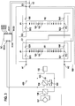
- FIG. 3 shows a charging circuit 400 according to the invention for a vehicle with two electrical energy storage units R1 and R2 according to a third embodiment.
- a spatially separate structure of the electrical energy storage units R1 and R2 is possible by a first fourth switch S41, which nevertheless allows a possible safety requirement for all-pole separation of the high-voltage-carrying components, for example for contact protection to the outside.
- the electrical energy storage units R1 and R2 together with associated switches are installed in separate housings G1 and G2, respectively, whereby in particular flexibility with regard to the installation space design can be obtained.
- the first fourth switch S41 is to be closed in addition to the first third switch S31, so that a series circuit the electric energy storage units R1 and R2 is produced. Upon completion of the charging operation, the first fourth switch S41 is therefore to be opened in addition to the opening of the first third switch S31.
- the components located in the separate housings G1 and G2 are in each case identical, that is, the battery 100 can be constructed from identical modules or subsystems, which saves manufacturing costs and simplifies a possible replacement during repair.
- the charging circuit has a DC-DC converter DC with a first input DCE1 and a second input DCE2 and a first output DCA1 and a second output DCA2.
- the DC-DC converter DC can be integrated, for example, in an on-board charger, which also includes a rectifier. This is indicated by the three additional inputs ACE1, ACE2 and ACE3, which represent three-phase inputs and AC inputs, respectively.
- the first input DCE1 of the DC-DC converter DC is electrically conductively connected to the first input E1 of the charging circuit 400.
- the second input DCE2 of the DC-DC converter DC is electrically conductively connected to the second input E2 of the charging circuit 400.
- the first output DCA1 of the DC-DC converter DC is electrically conductively connected to the first output A1 of the charging circuit 400.
- the second output DCA2 of the DC-DC converter DC is connected to the second output A2 of the charging circuit 400.
- the DC-DC converter DC can thus convert the voltage applied between the inputs E1 and E2 to a voltage suitable for the aforementioned electrical components and thus supply them with electrical energy even when the switches S11, S21, S12, S22 are open. This requires that the electrical energy storage units R1 and R2 are charged to the same extent. Possible compensation processes are therefore not absolutely necessary.
- the state of charge difference can be compensated for example during the charging process, for example by closing the first first switch S11 and the first second switch S21 with the electric energy storage unit R1 the outputs DCA1, DCA2 of the DC-DC converter DC is connected and depending on the consumption of the electrical components 102 to 107 and the control of the DC-DC converter DC, the electrical energy storage unit R1 is additionally charged or discharged.
- you can Compensation operations during the restoration of parallel connection can be prevented.
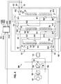
- FIG. 4 shows a charging circuit 500 according to the invention for a vehicle with three electrical energy storage units R1, R2 and R3 according to a fifth embodiment.
- the charging circuit has a fifth switch S51 and a sixth switch S61, which allow the first electrical energy storage unit R1 to be connected in series with the third electrical energy storage unit R3 it is possible to connect any two electrical energy storage units in series.
- Switches 109, 110, 111 and 112 serve, in particular, to prevent inadmissibly high voltages at the electrical energy storage units R1, R2 and R3 during charging operation or to provide the all-pole separation from the potential of the electrical energy storage units, in particular for externally located connections to the housings G1 , G2 and G3.
- x denotes a closed switch position and "o" an open switch position.
- x / o indicates that both a closed and an open switch position is possible.
- the preferred way of supplying power to connected electrical components during charging is, however, through the DC-DC converter integrated in an on-board charger, for example, which supplies the electrical energy required for this directly from one of the inputs E1 and E2 connected electrical energy source refers. If this is the case, the switches S11, S21, S12, S22, S13 and S23 can remain in the open position during the charging operation, since the electrical components 102 to 107 are supplied by the DC-DC converter DC.
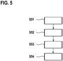
- FIG. 5 shows a flow diagram of the disclosed method according to a first embodiment of an electrical energy storage system with two electrical energy storage units R1 and R2, as for example in FIG. 1 is shown.
- the initial position of all switches for the following exemplary description is that all switches are open.
- the two electrical energy storage units are selected and positively decided that electrical components connected to the first output A1 and the second output A2, for example an air-conditioning compressor, are supplied with electrical energy during charging by the DC-DC converter DC.
- the first switch S11 and the second switch S21 of the electrical energy storage units R1 and R2 to be charged are opened, if they are not already in this position.
- a third step S53 the switch S31 connecting the electrical energy storage units R1 and R2 in series is closed.
- a fourth step S54 the two switches 108 are closed and the electric power supply is started by means of a power source connected to the first input E1 and the second input E2, wherein the electrical components connected to the first output A1 and the second output A2 by the DC-DC converter DC be supplied with electrical energy.
Landscapes
- Engineering & Computer Science (AREA)
- Power Engineering (AREA)
- Transportation (AREA)
- Mechanical Engineering (AREA)
- Charge And Discharge Circuits For Batteries Or The Like (AREA)
- Electric Propulsion And Braking For Vehicles (AREA)
- Dc-Dc Converters (AREA)
Applications Claiming Priority (1)
| Application Number | Priority Date | Filing Date | Title |
|---|---|---|---|
| DE102017201604.3A DE102017201604A1 (de) | 2017-02-01 | 2017-02-01 | Ladeschaltung mit Gleichspannungswandler und Ladeverfahren für ein elektrisches Energiespeichersystem |
Publications (3)
| Publication Number | Publication Date |
|---|---|
| EP3358701A2 true EP3358701A2 (fr) | 2018-08-08 |
| EP3358701A3 EP3358701A3 (fr) | 2018-08-15 |
| EP3358701B1 EP3358701B1 (fr) | 2019-12-18 |
Family
ID=61054173
Family Applications (1)
| Application Number | Title | Priority Date | Filing Date |
|---|---|---|---|
| EP18153126.0A Active EP3358701B1 (fr) | 2017-02-01 | 2018-01-24 | Circuit de charge pourvu de convertisseur continu-continu et procédé de charge pour un système d'accumulation d'énergie électrique |
Country Status (3)
| Country | Link |
|---|---|
| EP (1) | EP3358701B1 (fr) |
| CN (1) | CN108377010B (fr) |
| DE (1) | DE102017201604A1 (fr) |
Cited By (2)
| Publication number | Priority date | Publication date | Assignee | Title |
|---|---|---|---|---|
| EP3479455B1 (fr) * | 2016-07-01 | 2020-08-05 | Daimler AG | Dispositif à accumulateurs d'énergie pour véhicule automobile |
| US11469600B2 (en) | 2020-07-01 | 2022-10-11 | Robert Bosch Gmbh | Electrical energy store, device and method for operating an electrical energy store |
Families Citing this family (1)
| Publication number | Priority date | Publication date | Assignee | Title |
|---|---|---|---|---|
| DE102019129705A1 (de) * | 2019-11-05 | 2021-05-06 | Bayerische Motoren Werke Aktiengesellschaft | Mehrspannungs-Speichersystem für ein zumindest teilweise elektrisch angetriebenes Fahrzeug |
Citations (5)
| Publication number | Priority date | Publication date | Assignee | Title |
|---|---|---|---|---|
| US20050052154A1 (en) | 2002-09-11 | 2005-03-10 | Kavounas Gregory T. | Reconfigurable defibrillator battery module and method |
| US20070139012A1 (en) | 2005-11-01 | 2007-06-21 | Aerovironment, Inc. | Motive power dual battery pack |
| JP2012065435A (ja) | 2010-09-15 | 2012-03-29 | Nikon Corp | 振動アクチュエータ、レンズ鏡筒及びカメラ |
| US20130106357A1 (en) | 2011-10-31 | 2013-05-02 | Cobasys, Llc | Intelligent charging and discharging system for parallel configuration of series cells with semiconductor switching |
| US20130175865A1 (en) | 2012-01-06 | 2013-07-11 | Hon Hai Precision Industry Co., Ltd. | System and method for charging and discharging battery |
Family Cites Families (13)
| Publication number | Priority date | Publication date | Assignee | Title |
|---|---|---|---|---|
| JP3311670B2 (ja) * | 1998-04-09 | 2002-08-05 | 株式会社岡村研究所 | 直並列切換電源装置 |
| US6326771B1 (en) | 1999-03-08 | 2001-12-04 | 02 Micro International Limited | Buffer battery power supply system |
| DE102004031216A1 (de) * | 2004-06-28 | 2006-01-19 | Siemens Ag | Vorrichtung und Verfahren zum Ladungsausgleich in Reihe geschalteter Energiespeicher |
| KR101077154B1 (ko) * | 2008-04-22 | 2011-10-27 | 한국과학기술원 | 직렬연결 배터리 스트링을 위한 2단 전하 균일 방법 및장치 |
| JP5821256B2 (ja) | 2010-06-09 | 2015-11-24 | 日産自動車株式会社 | バッテリ充電システム |
| WO2013118271A1 (fr) * | 2012-02-09 | 2013-08-15 | 三菱電機株式会社 | Système d'accumulateur parallèle et son procédé de commande |
| EP2810815A1 (fr) * | 2013-06-07 | 2014-12-10 | Flextronics International Kft. | Système d'accumulation d'énergie et procédé d'ajustement de la tension d'un accumulateur d'énergie |
| DE102013212682B4 (de) * | 2013-06-28 | 2017-03-02 | Robert Bosch Gmbh | Energiespeichereinrichtung mit Gleichspannungsversorgungsschaltung und Verfahren zum Bereitstellen einer Gleichspannung aus einer Energiespeichereinrichtung |
| DE102014004790B4 (de) | 2014-04-02 | 2021-02-04 | Audi Ag | Verfahren zum Betrieb einer Energiespeichereinrichtung in einem Kraftfahrzeug und Kraftfahrzeug |
| DE102014109430A1 (de) | 2014-07-07 | 2016-01-07 | Dr. Ing. H.C. F. Porsche Aktiengesellschaft | Energiespeichersystem und Verfahren zum Betrieb eines Energiespeichersystems |
| DE102015214732A1 (de) | 2015-08-03 | 2017-02-09 | Audi Ag | Verfahren zum Betrieb einer Energiespeichereinrichtung sowie Kraftfahrzeug mit einer Energiespeichereinrichtung |
| DE102016223470A1 (de) | 2015-12-18 | 2017-06-22 | Robert Bosch Gmbh | Ladeschaltung und Ladeverfahren für ein elektrisches Energiespeichersystem |
| DE102016201520A1 (de) | 2016-02-02 | 2017-08-03 | Bayerische Motoren Werke Aktiengesellschaft | Speichersystem für ein Fahrzeug |
-
2017
- 2017-02-01 DE DE102017201604.3A patent/DE102017201604A1/de not_active Withdrawn
-
2018
- 2018-01-24 EP EP18153126.0A patent/EP3358701B1/fr active Active
- 2018-02-01 CN CN201810101031.4A patent/CN108377010B/zh active Active
Patent Citations (5)
| Publication number | Priority date | Publication date | Assignee | Title |
|---|---|---|---|---|
| US20050052154A1 (en) | 2002-09-11 | 2005-03-10 | Kavounas Gregory T. | Reconfigurable defibrillator battery module and method |
| US20070139012A1 (en) | 2005-11-01 | 2007-06-21 | Aerovironment, Inc. | Motive power dual battery pack |
| JP2012065435A (ja) | 2010-09-15 | 2012-03-29 | Nikon Corp | 振動アクチュエータ、レンズ鏡筒及びカメラ |
| US20130106357A1 (en) | 2011-10-31 | 2013-05-02 | Cobasys, Llc | Intelligent charging and discharging system for parallel configuration of series cells with semiconductor switching |
| US20130175865A1 (en) | 2012-01-06 | 2013-07-11 | Hon Hai Precision Industry Co., Ltd. | System and method for charging and discharging battery |
Cited By (3)
| Publication number | Priority date | Publication date | Assignee | Title |
|---|---|---|---|---|
| EP3479455B1 (fr) * | 2016-07-01 | 2020-08-05 | Daimler AG | Dispositif à accumulateurs d'énergie pour véhicule automobile |
| US10800286B2 (en) | 2016-07-01 | 2020-10-13 | Daimler Ag | Energy storage device for a motor vehicle |
| US11469600B2 (en) | 2020-07-01 | 2022-10-11 | Robert Bosch Gmbh | Electrical energy store, device and method for operating an electrical energy store |
Also Published As
| Publication number | Publication date |
|---|---|
| EP3358701A3 (fr) | 2018-08-15 |
| DE102017201604A1 (de) | 2018-08-02 |
| EP3358701B1 (fr) | 2019-12-18 |
| CN108377010B (zh) | 2023-04-07 |
| CN108377010A (zh) | 2018-08-07 |
Similar Documents
| Publication | Publication Date | Title |
|---|---|---|
| EP3391505B1 (fr) | Circuit de charge et procédé de charge pour un système électrique d'accumulation d'énergie | |
| EP3616295B1 (fr) | Circuit et procédé de charge pour un système de stockage d'énergie électrique | |
| WO2002066293A1 (fr) | Reseau de bord de vehicule automobile | |
| DE102010041040A1 (de) | Energieversorgungsnetz und Verfahren zum Laden mindestens einer als Energiespeicher für einen Gleichspannungszwischenkreis dienenden Energiespeicherzelle in einem Energieversorgungsnetz | |
| DE102016225513A1 (de) | Schaltungsanordnung und Betriebsverfahren für ein elektrisches Energiespeichersystem | |
| DE102017010998A1 (de) | Energiespeichervorrichtung und Energiesystemen für ein Kraftfahrzeug | |
| DE102017210611A1 (de) | Elektrische Energieliefervorrichtung mit einer Stromschienenmatrix sowie Verfahren zum Betreiben der Energieliefervorrichtung | |
| WO2021089281A1 (fr) | Système de stockage à plusieurs tensions pour un véhicule au moins partiellement électrique | |
| DE102017210617A1 (de) | Elektrische Energieliefervorrichtung mit Stromschienenmatrix sowie Verfahren zum Betreiben der Energieliefervorrichtung | |
| DE102017210618A1 (de) | Elektrische Energieliefervorrichtung mit einer Vielzahl von Nutzeinheiten, die zu Strängen verschaltet sind, sowie Verfahren zum Betreiben der Energieliefervorrichtung | |
| EP2528767B1 (fr) | Système de batterie pour véhicules micro-hybrides à consommateurs de forte puissance | |
| EP3358701B1 (fr) | Circuit de charge pourvu de convertisseur continu-continu et procédé de charge pour un système d'accumulation d'énergie électrique | |
| EP4272990A1 (fr) | Dispositif de charge supplémentaire pour une boîte à lettres ac et boîte à lettres ac-dc dotée d'un tel dispositif de charge supplémentaire | |
| DE102021109443B4 (de) | Verfahren zum Durchführen eines Vorladevorgangs eines elektrischen Bordnetzes eines Fahrzeugs und elektrisches Bordnetz für ein Fahrzeug | |
| DE102016002459A1 (de) | Elektrische Anlage für ein elektrisch antreibbares Kraftfahrzeug | |
| DE102017209451A1 (de) | Elektrisches Energieversorgungssystem, Verfahren und Computerprogramm zum Betreiben des Energieversorgungssystems und Computerprogrammprodukt | |
| DE102010041028A1 (de) | Energieversorgungsnetz und Verfahren zum Laden mindestens einer als Energiespeicher für einen Gleichspannungszwischenkreis dienenden Energiespeicherzelle in einem Energieversorgungsnetz | |
| DE102015006280A1 (de) | Fahrzeug und elektrische Antriebsvorrichtung für ein Fahrzeug | |
| DE102011006096A1 (de) | Laderegelungssystem | |
| DE102020004741A1 (de) | Elektrisches Bordnetz für ein zumindest teilweise elektrisch betriebenes Kraftfahrzeug, sowie Kraftfahrzeug | |
| DE102010017439A1 (de) | Schaltungsanordnung und Verfahren zum Ausgleich von unterschiedlichen Ladezuständen von Zellen eines Energiespeichers | |
| DE102021213459B3 (de) | Schalteinrichtung und Verfahren zum Aufladen eines elektrischen Energiespeichers und Elektrofahrzeug | |
| DE102024203710A1 (de) | Schaltungsanordnung für ein elektrochemisches Energiespeichersystem | |
| DE102019121277A1 (de) | Mehrspannungs-Speichersystem für ein zumindest teilweise elektrisch angetriebenes Fahrzeug | |
| DE102018220430A1 (de) | Elektrochemisches Energiespeichersystem |
Legal Events
| Date | Code | Title | Description |
|---|---|---|---|
| PUAI | Public reference made under article 153(3) epc to a published international application that has entered the european phase |
Free format text: ORIGINAL CODE: 0009012 |
|
| STAA | Information on the status of an ep patent application or granted ep patent |
Free format text: STATUS: THE APPLICATION HAS BEEN PUBLISHED |
|
| PUAL | Search report despatched |
Free format text: ORIGINAL CODE: 0009013 |
|
| AK | Designated contracting states |
Kind code of ref document: A2 Designated state(s): AL AT BE BG CH CY CZ DE DK EE ES FI FR GB GR HR HU IE IS IT LI LT LU LV MC MK MT NL NO PL PT RO RS SE SI SK SM TR |
|
| AX | Request for extension of the european patent |
Extension state: BA ME |
|
| AK | Designated contracting states |
Kind code of ref document: A3 Designated state(s): AL AT BE BG CH CY CZ DE DK EE ES FI FR GB GR HR HU IE IS IT LI LT LU LV MC MK MT NL NO PL PT RO RS SE SI SK SM TR |
|
| AX | Request for extension of the european patent |
Extension state: BA ME |
|
| RIC1 | Information provided on ipc code assigned before grant |
Ipc: H02J 7/00 20060101AFI20180710BHEP |
|
| STAA | Information on the status of an ep patent application or granted ep patent |
Free format text: STATUS: REQUEST FOR EXAMINATION WAS MADE |
|
| 17P | Request for examination filed |
Effective date: 20190215 |
|
| RBV | Designated contracting states (corrected) |
Designated state(s): AL AT BE BG CH CY CZ DE DK EE ES FI FR GB GR HR HU IE IS IT LI LT LU LV MC MK MT NL NO PL PT RO RS SE SI SK SM TR |
|
| GRAP | Despatch of communication of intention to grant a patent |
Free format text: ORIGINAL CODE: EPIDOSNIGR1 |
|
| STAA | Information on the status of an ep patent application or granted ep patent |
Free format text: STATUS: GRANT OF PATENT IS INTENDED |
|
| INTG | Intention to grant announced |
Effective date: 20190716 |
|
| GRAS | Grant fee paid |
Free format text: ORIGINAL CODE: EPIDOSNIGR3 |
|
| GRAA | (expected) grant |
Free format text: ORIGINAL CODE: 0009210 |
|
| STAA | Information on the status of an ep patent application or granted ep patent |
Free format text: STATUS: THE PATENT HAS BEEN GRANTED |
|
| AK | Designated contracting states |
Kind code of ref document: B1 Designated state(s): AL AT BE BG CH CY CZ DE DK EE ES FI FR GB GR HR HU IE IS IT LI LT LU LV MC MK MT NL NO PL PT RO RS SE SI SK SM TR |
|
| REG | Reference to a national code |
Ref country code: CH Ref legal event code: EP |
|
| REG | Reference to a national code |
Ref country code: IE Ref legal event code: FG4D Free format text: LANGUAGE OF EP DOCUMENT: GERMAN |
|
| REG | Reference to a national code |
Ref country code: DE Ref legal event code: R096 Ref document number: 502018000503 Country of ref document: DE |
|
| REG | Reference to a national code |
Ref country code: AT Ref legal event code: REF Ref document number: 1215632 Country of ref document: AT Kind code of ref document: T Effective date: 20200115 |
|
| REG | Reference to a national code |
Ref country code: NL Ref legal event code: MP Effective date: 20191218 |
|
| RAP2 | Party data changed (patent owner data changed or rights of a patent transferred) |
Owner name: ROBERT BOSCH GMBH |
|
| PG25 | Lapsed in a contracting state [announced via postgrant information from national office to epo] |
Ref country code: SE Free format text: LAPSE BECAUSE OF FAILURE TO SUBMIT A TRANSLATION OF THE DESCRIPTION OR TO PAY THE FEE WITHIN THE PRESCRIBED TIME-LIMIT Effective date: 20191218 Ref country code: LV Free format text: LAPSE BECAUSE OF FAILURE TO SUBMIT A TRANSLATION OF THE DESCRIPTION OR TO PAY THE FEE WITHIN THE PRESCRIBED TIME-LIMIT Effective date: 20191218 Ref country code: GR Free format text: LAPSE BECAUSE OF FAILURE TO SUBMIT A TRANSLATION OF THE DESCRIPTION OR TO PAY THE FEE WITHIN THE PRESCRIBED TIME-LIMIT Effective date: 20200319 Ref country code: BG Free format text: LAPSE BECAUSE OF FAILURE TO SUBMIT A TRANSLATION OF THE DESCRIPTION OR TO PAY THE FEE WITHIN THE PRESCRIBED TIME-LIMIT Effective date: 20200318 Ref country code: LT Free format text: LAPSE BECAUSE OF FAILURE TO SUBMIT A TRANSLATION OF THE DESCRIPTION OR TO PAY THE FEE WITHIN THE PRESCRIBED TIME-LIMIT Effective date: 20191218 Ref country code: NO Free format text: LAPSE BECAUSE OF FAILURE TO SUBMIT A TRANSLATION OF THE DESCRIPTION OR TO PAY THE FEE WITHIN THE PRESCRIBED TIME-LIMIT Effective date: 20200318 Ref country code: FI Free format text: LAPSE BECAUSE OF FAILURE TO SUBMIT A TRANSLATION OF THE DESCRIPTION OR TO PAY THE FEE WITHIN THE PRESCRIBED TIME-LIMIT Effective date: 20191218 |
|
| REG | Reference to a national code |
Ref country code: LT Ref legal event code: MG4D |
|
| PG25 | Lapsed in a contracting state [announced via postgrant information from national office to epo] |
Ref country code: HR Free format text: LAPSE BECAUSE OF FAILURE TO SUBMIT A TRANSLATION OF THE DESCRIPTION OR TO PAY THE FEE WITHIN THE PRESCRIBED TIME-LIMIT Effective date: 20191218 Ref country code: RS Free format text: LAPSE BECAUSE OF FAILURE TO SUBMIT A TRANSLATION OF THE DESCRIPTION OR TO PAY THE FEE WITHIN THE PRESCRIBED TIME-LIMIT Effective date: 20191218 |
|
| PG25 | Lapsed in a contracting state [announced via postgrant information from national office to epo] |
Ref country code: AL Free format text: LAPSE BECAUSE OF FAILURE TO SUBMIT A TRANSLATION OF THE DESCRIPTION OR TO PAY THE FEE WITHIN THE PRESCRIBED TIME-LIMIT Effective date: 20191218 |
|
| PG25 | Lapsed in a contracting state [announced via postgrant information from national office to epo] |
Ref country code: CZ Free format text: LAPSE BECAUSE OF FAILURE TO SUBMIT A TRANSLATION OF THE DESCRIPTION OR TO PAY THE FEE WITHIN THE PRESCRIBED TIME-LIMIT Effective date: 20191218 Ref country code: NL Free format text: LAPSE BECAUSE OF FAILURE TO SUBMIT A TRANSLATION OF THE DESCRIPTION OR TO PAY THE FEE WITHIN THE PRESCRIBED TIME-LIMIT Effective date: 20191218 Ref country code: RO Free format text: LAPSE BECAUSE OF FAILURE TO SUBMIT A TRANSLATION OF THE DESCRIPTION OR TO PAY THE FEE WITHIN THE PRESCRIBED TIME-LIMIT Effective date: 20191218 Ref country code: EE Free format text: LAPSE BECAUSE OF FAILURE TO SUBMIT A TRANSLATION OF THE DESCRIPTION OR TO PAY THE FEE WITHIN THE PRESCRIBED TIME-LIMIT Effective date: 20191218 Ref country code: PT Free format text: LAPSE BECAUSE OF FAILURE TO SUBMIT A TRANSLATION OF THE DESCRIPTION OR TO PAY THE FEE WITHIN THE PRESCRIBED TIME-LIMIT Effective date: 20200513 |
|
| PG25 | Lapsed in a contracting state [announced via postgrant information from national office to epo] |
Ref country code: SM Free format text: LAPSE BECAUSE OF FAILURE TO SUBMIT A TRANSLATION OF THE DESCRIPTION OR TO PAY THE FEE WITHIN THE PRESCRIBED TIME-LIMIT Effective date: 20191218 Ref country code: SK Free format text: LAPSE BECAUSE OF FAILURE TO SUBMIT A TRANSLATION OF THE DESCRIPTION OR TO PAY THE FEE WITHIN THE PRESCRIBED TIME-LIMIT Effective date: 20191218 Ref country code: IS Free format text: LAPSE BECAUSE OF FAILURE TO SUBMIT A TRANSLATION OF THE DESCRIPTION OR TO PAY THE FEE WITHIN THE PRESCRIBED TIME-LIMIT Effective date: 20200418 |
|
| REG | Reference to a national code |
Ref country code: DE Ref legal event code: R097 Ref document number: 502018000503 Country of ref document: DE |
|
| PG25 | Lapsed in a contracting state [announced via postgrant information from national office to epo] |
Ref country code: MC Free format text: LAPSE BECAUSE OF FAILURE TO SUBMIT A TRANSLATION OF THE DESCRIPTION OR TO PAY THE FEE WITHIN THE PRESCRIBED TIME-LIMIT Effective date: 20191218 |
|
| REG | Reference to a national code |
Ref country code: BE Ref legal event code: MM Effective date: 20200131 |
|
| PLBE | No opposition filed within time limit |
Free format text: ORIGINAL CODE: 0009261 |
|
| STAA | Information on the status of an ep patent application or granted ep patent |
Free format text: STATUS: NO OPPOSITION FILED WITHIN TIME LIMIT |
|
| PG25 | Lapsed in a contracting state [announced via postgrant information from national office to epo] |
Ref country code: DK Free format text: LAPSE BECAUSE OF FAILURE TO SUBMIT A TRANSLATION OF THE DESCRIPTION OR TO PAY THE FEE WITHIN THE PRESCRIBED TIME-LIMIT Effective date: 20191218 Ref country code: ES Free format text: LAPSE BECAUSE OF FAILURE TO SUBMIT A TRANSLATION OF THE DESCRIPTION OR TO PAY THE FEE WITHIN THE PRESCRIBED TIME-LIMIT Effective date: 20191218 Ref country code: LU Free format text: LAPSE BECAUSE OF NON-PAYMENT OF DUE FEES Effective date: 20200124 |
|
| 26N | No opposition filed |
Effective date: 20200921 |
|
| PG25 | Lapsed in a contracting state [announced via postgrant information from national office to epo] |
Ref country code: SI Free format text: LAPSE BECAUSE OF FAILURE TO SUBMIT A TRANSLATION OF THE DESCRIPTION OR TO PAY THE FEE WITHIN THE PRESCRIBED TIME-LIMIT Effective date: 20191218 Ref country code: BE Free format text: LAPSE BECAUSE OF NON-PAYMENT OF DUE FEES Effective date: 20200131 |
|
| PG25 | Lapsed in a contracting state [announced via postgrant information from national office to epo] |
Ref country code: IE Free format text: LAPSE BECAUSE OF NON-PAYMENT OF DUE FEES Effective date: 20200124 Ref country code: IT Free format text: LAPSE BECAUSE OF FAILURE TO SUBMIT A TRANSLATION OF THE DESCRIPTION OR TO PAY THE FEE WITHIN THE PRESCRIBED TIME-LIMIT Effective date: 20191218 |
|
| PG25 | Lapsed in a contracting state [announced via postgrant information from national office to epo] |
Ref country code: PL Free format text: LAPSE BECAUSE OF FAILURE TO SUBMIT A TRANSLATION OF THE DESCRIPTION OR TO PAY THE FEE WITHIN THE PRESCRIBED TIME-LIMIT Effective date: 20191218 |
|
| REG | Reference to a national code |
Ref country code: CH Ref legal event code: PL |
|
| PG25 | Lapsed in a contracting state [announced via postgrant information from national office to epo] |
Ref country code: CH Free format text: LAPSE BECAUSE OF NON-PAYMENT OF DUE FEES Effective date: 20210131 Ref country code: LI Free format text: LAPSE BECAUSE OF NON-PAYMENT OF DUE FEES Effective date: 20210131 |
|
| PG25 | Lapsed in a contracting state [announced via postgrant information from national office to epo] |
Ref country code: TR Free format text: LAPSE BECAUSE OF FAILURE TO SUBMIT A TRANSLATION OF THE DESCRIPTION OR TO PAY THE FEE WITHIN THE PRESCRIBED TIME-LIMIT Effective date: 20191218 Ref country code: MT Free format text: LAPSE BECAUSE OF FAILURE TO SUBMIT A TRANSLATION OF THE DESCRIPTION OR TO PAY THE FEE WITHIN THE PRESCRIBED TIME-LIMIT Effective date: 20191218 Ref country code: CY Free format text: LAPSE BECAUSE OF FAILURE TO SUBMIT A TRANSLATION OF THE DESCRIPTION OR TO PAY THE FEE WITHIN THE PRESCRIBED TIME-LIMIT Effective date: 20191218 |
|
| PG25 | Lapsed in a contracting state [announced via postgrant information from national office to epo] |
Ref country code: MK Free format text: LAPSE BECAUSE OF FAILURE TO SUBMIT A TRANSLATION OF THE DESCRIPTION OR TO PAY THE FEE WITHIN THE PRESCRIBED TIME-LIMIT Effective date: 20191218 |
|
| REG | Reference to a national code |
Ref country code: AT Ref legal event code: MM01 Ref document number: 1215632 Country of ref document: AT Kind code of ref document: T Effective date: 20230124 |
|
| PG25 | Lapsed in a contracting state [announced via postgrant information from national office to epo] |
Ref country code: AT Free format text: LAPSE BECAUSE OF NON-PAYMENT OF DUE FEES Effective date: 20230124 |
|
| PG25 | Lapsed in a contracting state [announced via postgrant information from national office to epo] |
Ref country code: AT Free format text: LAPSE BECAUSE OF NON-PAYMENT OF DUE FEES Effective date: 20230124 |
|
| PGFP | Annual fee paid to national office [announced via postgrant information from national office to epo] |
Ref country code: GB Payment date: 20260122 Year of fee payment: 9 |
|
| PGFP | Annual fee paid to national office [announced via postgrant information from national office to epo] |
Ref country code: DE Payment date: 20260319 Year of fee payment: 9 |
|
| PGFP | Annual fee paid to national office [announced via postgrant information from national office to epo] |
Ref country code: AT Payment date: 20260410 Year of fee payment: 5 |
|
| PGFP | Annual fee paid to national office [announced via postgrant information from national office to epo] |
Ref country code: FR Payment date: 20260127 Year of fee payment: 9 |