EP3358729B1 - Vorrichtung zur steuerung eines motors - Google Patents
Vorrichtung zur steuerung eines motors Download PDFInfo
- Publication number
- EP3358729B1 EP3358729B1 EP17206136.8A EP17206136A EP3358729B1 EP 3358729 B1 EP3358729 B1 EP 3358729B1 EP 17206136 A EP17206136 A EP 17206136A EP 3358729 B1 EP3358729 B1 EP 3358729B1
- Authority
- EP
- European Patent Office
- Prior art keywords
- braking resistor
- voltage
- time
- switching unit
- temperature
- Prior art date
- Legal status (The legal status is an assumption and is not a legal conclusion. Google has not performed a legal analysis and makes no representation as to the accuracy of the status listed.)
- Active
Links
Images

Classifications
-
- H—ELECTRICITY
- H02—GENERATION; CONVERSION OR DISTRIBUTION OF ELECTRIC POWER
- H02P—CONTROL OR REGULATION OF ELECTRIC MOTORS, ELECTRIC GENERATORS OR DYNAMO-ELECTRIC CONVERTERS; CONTROLLING TRANSFORMERS, REACTORS OR CHOKE COILS
- H02P3/00—Arrangements for stopping or slowing electric motors, generators, or dynamo-electric converters
- H02P3/06—Arrangements for stopping or slowing electric motors, generators, or dynamo-electric converters for stopping or slowing an individual dynamo-electric motor or dynamo-electric converter
- H02P3/18—Arrangements for stopping or slowing electric motors, generators, or dynamo-electric converters for stopping or slowing an individual dynamo-electric motor or dynamo-electric converter for stopping or slowing an AC motor
- H02P3/22—Arrangements for stopping or slowing electric motors, generators, or dynamo-electric converters for stopping or slowing an individual dynamo-electric motor or dynamo-electric converter for stopping or slowing an AC motor by short-circuit or resistive braking
-
- H—ELECTRICITY
- H02—GENERATION; CONVERSION OR DISTRIBUTION OF ELECTRIC POWER
- H02M—APPARATUS FOR CONVERSION BETWEEN AC AND AC, BETWEEN AC AND DC, OR BETWEEN DC AND DC, AND FOR USE WITH MAINS OR SIMILAR POWER SUPPLY SYSTEMS; CONVERSION OF DC OR AC INPUT POWER INTO SURGE OUTPUT POWER; CONTROL OR REGULATION THEREOF
- H02M1/00—Details of apparatus for conversion
- H02M1/0003—Details of control, feedback or regulation circuits
- H02M1/0038—Circuits or arrangements for suppressing, e.g. by masking incorrect turn-on or turn-off signals, e.g. due to current spikes in current mode control
-
- H—ELECTRICITY
- H02—GENERATION; CONVERSION OR DISTRIBUTION OF ELECTRIC POWER
- H02M—APPARATUS FOR CONVERSION BETWEEN AC AND AC, BETWEEN AC AND DC, OR BETWEEN DC AND DC, AND FOR USE WITH MAINS OR SIMILAR POWER SUPPLY SYSTEMS; CONVERSION OF DC OR AC INPUT POWER INTO SURGE OUTPUT POWER; CONTROL OR REGULATION THEREOF
- H02M1/00—Details of apparatus for conversion
- H02M1/32—Means for protecting converters other than automatic disconnection
-
- H—ELECTRICITY
- H02—GENERATION; CONVERSION OR DISTRIBUTION OF ELECTRIC POWER
- H02M—APPARATUS FOR CONVERSION BETWEEN AC AND AC, BETWEEN AC AND DC, OR BETWEEN DC AND DC, AND FOR USE WITH MAINS OR SIMILAR POWER SUPPLY SYSTEMS; CONVERSION OF DC OR AC INPUT POWER INTO SURGE OUTPUT POWER; CONTROL OR REGULATION THEREOF
- H02M7/00—Conversion of AC power input into DC power output; Conversion of DC power input into AC power output
- H02M7/42—Conversion of DC power input into AC power output without possibility of reversal
- H02M7/44—Conversion of DC power input into AC power output without possibility of reversal by static converters
- H02M7/48—Conversion of DC power input into AC power output without possibility of reversal by static converters using discharge tubes with control electrode or semiconductor devices with control electrode
-
- H—ELECTRICITY
- H02—GENERATION; CONVERSION OR DISTRIBUTION OF ELECTRIC POWER
- H02P—CONTROL OR REGULATION OF ELECTRIC MOTORS, ELECTRIC GENERATORS OR DYNAMO-ELECTRIC CONVERTERS; CONTROLLING TRANSFORMERS, REACTORS OR CHOKE COILS
- H02P27/00—Arrangements or methods for the control of AC motors characterised by the kind of supply voltage
- H02P27/04—Arrangements or methods for the control of AC motors characterised by the kind of supply voltage using variable-frequency supply voltage, e.g. inverter or converter supply voltage
- H02P27/06—Arrangements or methods for the control of AC motors characterised by the kind of supply voltage using variable-frequency supply voltage, e.g. inverter or converter supply voltage using DC to AC converters or inverters
-
- H—ELECTRICITY
- H02—GENERATION; CONVERSION OR DISTRIBUTION OF ELECTRIC POWER
- H02P—CONTROL OR REGULATION OF ELECTRIC MOTORS, ELECTRIC GENERATORS OR DYNAMO-ELECTRIC CONVERTERS; CONTROLLING TRANSFORMERS, REACTORS OR CHOKE COILS
- H02P29/00—Arrangements for regulating or controlling electric motors, appropriate for both AC and DC motors
- H02P29/60—Controlling or determining the temperature of the motor or of the drive
- H02P29/68—Controlling or determining the temperature of the motor or of the drive based on the temperature of a drive component or a semiconductor component
-
- H—ELECTRICITY
- H02—GENERATION; CONVERSION OR DISTRIBUTION OF ELECTRIC POWER
- H02P—CONTROL OR REGULATION OF ELECTRIC MOTORS, ELECTRIC GENERATORS OR DYNAMO-ELECTRIC CONVERTERS; CONTROLLING TRANSFORMERS, REACTORS OR CHOKE COILS
- H02P3/00—Arrangements for stopping or slowing electric motors, generators, or dynamo-electric converters
- H02P3/06—Arrangements for stopping or slowing electric motors, generators, or dynamo-electric converters for stopping or slowing an individual dynamo-electric motor or dynamo-electric converter
- H02P3/08—Arrangements for stopping or slowing electric motors, generators, or dynamo-electric converters for stopping or slowing an individual dynamo-electric motor or dynamo-electric converter for stopping or slowing a DC motor
- H02P3/14—Arrangements for stopping or slowing electric motors, generators, or dynamo-electric converters for stopping or slowing an individual dynamo-electric motor or dynamo-electric converter for stopping or slowing a DC motor by regenerative braking
-
- H—ELECTRICITY
- H02—GENERATION; CONVERSION OR DISTRIBUTION OF ELECTRIC POWER
- H02M—APPARATUS FOR CONVERSION BETWEEN AC AND AC, BETWEEN AC AND DC, OR BETWEEN DC AND DC, AND FOR USE WITH MAINS OR SIMILAR POWER SUPPLY SYSTEMS; CONVERSION OF DC OR AC INPUT POWER INTO SURGE OUTPUT POWER; CONTROL OR REGULATION THEREOF
- H02M1/00—Details of apparatus for conversion
- H02M1/32—Means for protecting converters other than automatic disconnection
- H02M1/322—Means for rapidly discharging a capacitor of the converter for protecting electrical components or for preventing electrical shock
-
- H—ELECTRICITY
- H02—GENERATION; CONVERSION OR DISTRIBUTION OF ELECTRIC POWER
- H02M—APPARATUS FOR CONVERSION BETWEEN AC AND AC, BETWEEN AC AND DC, OR BETWEEN DC AND DC, AND FOR USE WITH MAINS OR SIMILAR POWER SUPPLY SYSTEMS; CONVERSION OF DC OR AC INPUT POWER INTO SURGE OUTPUT POWER; CONTROL OR REGULATION THEREOF
- H02M1/00—Details of apparatus for conversion
- H02M1/32—Means for protecting converters other than automatic disconnection
- H02M1/327—Means for protecting converters other than automatic disconnection against abnormal temperatures
-
- H—ELECTRICITY
- H02—GENERATION; CONVERSION OR DISTRIBUTION OF ELECTRIC POWER
- H02M—APPARATUS FOR CONVERSION BETWEEN AC AND AC, BETWEEN AC AND DC, OR BETWEEN DC AND DC, AND FOR USE WITH MAINS OR SIMILAR POWER SUPPLY SYSTEMS; CONVERSION OF DC OR AC INPUT POWER INTO SURGE OUTPUT POWER; CONTROL OR REGULATION THEREOF
- H02M7/00—Conversion of AC power input into DC power output; Conversion of DC power input into AC power output
- H02M7/42—Conversion of DC power input into AC power output without possibility of reversal
- H02M7/44—Conversion of DC power input into AC power output without possibility of reversal by static converters
- H02M7/48—Conversion of DC power input into AC power output without possibility of reversal by static converters using discharge tubes with control electrode or semiconductor devices with control electrode
- H02M7/53—Conversion of DC power input into AC power output without possibility of reversal by static converters using discharge tubes with control electrode or semiconductor devices with control electrode using devices of a triode or transistor type requiring continuous application of a control signal
- H02M7/537—Conversion of DC power input into AC power output without possibility of reversal by static converters using discharge tubes with control electrode or semiconductor devices with control electrode using devices of a triode or transistor type requiring continuous application of a control signal using semiconductor devices only, e.g. single switched pulse inverters
- H02M7/5387—Conversion of DC power input into AC power output without possibility of reversal by static converters using discharge tubes with control electrode or semiconductor devices with control electrode using devices of a triode or transistor type requiring continuous application of a control signal using semiconductor devices only, e.g. single switched pulse inverters in a bridge configuration
Definitions
- the present disclosure relates to an apparatus for controlling a motor.
- inverters are power conversion devices configured to convert a mains electricity alternating-current (AC) power into a direct-current (DC) power, convert the DC power to an AC power suitable for a motor, and then supply the AC power to the motor.
- AC alternating-current
- DC direct-current
- a diode rectifier is configured to allow power to be transferred in one direction. Accordingly, when the motor decelerates or applies regenerative braking, the power flowing reversely is not output to the system power source, but is accumulated in a DC link capacitor, and thus the DC link voltage increases. In order to prevent this effect, a braking resistor may be added to both ends of the DC link capacitor, thereby suppressing an increase in the DC link voltage and preventing damage to the inverter.
- Such a braking resistor produces heat while consuming energy to increase the DC link voltage. Accordingly, the usage rate of the braking resistor is limited to prevent the braking resistor from overheating.
- FIGS. 1 and 2 illustrate methods of limiting the usage rate of a conventional braking resistor, which limits the proportion of the time T_dec of a speed reduction rate section, in which the regenerative energy is generated, in the entire operation time.
- % ED T _ dec T _ acc + T _ steady + T _ dec + T _ stop ⁇ 100
- T acc denotes the time taken to accelerate up to a set frequency
- T_steady denotes the time for constant speed operation at the set frequency
- T_stop denotes the time for which the operation remains stopped until the operation is started again.
- the user sets a limit level of %ED, or the usage rate, and limits use of the braking resistor so as not to exceed the set level by calculating the actual %ED.
- % ED T _ dec T _ dec + T _ steady 1 + T _ acc + T _ steady 2 ⁇ 100
- the braking resistor when the motor decelerates slowly, the braking resistor can be used for a relatively long time since the regenerative energy is small. However, since only time is taken into consideration in limiting the usage rate of the braking resistor, the braking resistor may not be used properly. When the motor decelerates rapidly, the braking resistor should be used for a relatively short period of time since the regenerative energy is large. However, the braking resistor may not be used properly since only time is taken into consideration in limiting the usage rate of the braking resistor as in the previous case.
- the braking resistor may accumulate heat to overheat when the acceleration/speed reduction rate of the motor frequently occurs.
- the usage time and usage rate should be calculated after the braking resistor is selected, which causes inconvenience to the user.
- EP 2 506 423 discloses a power converting device that enables effective use of an allowable power capacity of a connected regenerative braking resistor by automatically adjusting an output voltage and deceleration time according to the power capacity.
- an apparatus for controlling a motor is provided according to claim 1.
- a braking resistor can be efficiently used by turning the braking resistor on or off according to the temperature of the braking resistor. Further, as operation is performed in conjunction with the temperature and DC link voltage of the braking resistor, the braking resistor can be used easily even if the usage rate of the braking resistor is not preset.
- the braking resistor can be prevented from overheating due to erroneously setting of the usage rate of the braking resistor.
- first, second, etc. may be used to explain various components, but the components are not limited thereto. These terms are used only for the purpose of distinguishing one component from another. For example, a "'first component” may be referred to as a “second component”, and similarly, a “second component” may also be referred to as a “first component” without departing from the scope of the present disclosure.
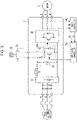
- FIG. 3 is a diagram schematically illustrating an inverter system to which an embodiment of the present disclosure is applied.
- an inverter 1 which receives three-phase alternating-current (AC) power and outputs power of a predetermined magnitude and frequency to a motor 2, includes a converter unit 10, a smoothing unit 20, an inverter unit 30, a main controller 40, a switching controller 50, a switching unit 60, a braking resistor 70, and a temperature sensor 75 for measuring the temperature of the braking resistor 70.
- AC alternating-current
- the converter unit 10 converts the input three-phase AC power into a direct-current (DC) voltage.
- the converter unit 10 may include a plurality of rectifier diodes, or may include a plurality of switching elements.
- the smoothing unit 20 includes a DC link capacitor and may smooth and store the DC voltage obtained through conversion in the converter unit 10.
- the inverter unit 30 may include a plurality of switching elements. The DC voltage stored in the DC link capacitor is converted into a voltage of a predetermined magnitude and frequency and output to the motor 2 under control of the switching controller 50.
- the braking resistor 70 is connected in parallel to the DC link capacitor and configured to consume the voltage stored in the DC link capacitor by turning on or off the switching unit 60. That is, when the switching unit 60 is in the ON state, the power applied to the DC link is consumed by the braking resistor 70. When the switching unit 60 is in the OFF state, the voltage applied to the DC link is provided to the inverter unit 30.
- the main controller 40 may generate a command frequency and command voltage based on the output current of the inverter unit 30 and provide the same to the switching controller 50. Based on the command frequency and the command voltage, the switching controller 50 may transmit, to the inverter unit 30, a control signal for controlling the plurality of switching elements of the inverter unit 30.
- the main controller 40 generates a control signal for controlling the switching unit 60 to switch the braking resistor 70 to the ON or OFF state and ON/OFF of the switching unit 60 may be controlled by the control signal.
- the main controller 40 may receive the temperature of the braking resistor 70. If the received temperature is higher than or equal to a reference temperature, the main controller 40 transmits, to the switching controller 50, a control signal for causing the braking resistor 70 to be turned off so as not to operate, and the switching controller 50 controls the switching unit 60 to be turned off by the control signal.
- the main controller 40 transmits, to the switching controller 50, a control signal for causing the braking resistor 70 to be turned on to operate, and the switching controller 50 controls the switching unit 60 to be turned on by the control signal.
- the main controller 40 applies hysteresis to prevent frequent occurrence of ON or OFF at the reference voltage and the reference temperature.
- the present disclosure is not limited thereto. That is, various methods for estimating the temperature of the braking resistor 70 may be used.
- the temperature of the braking resistor 70 may be estimated by measuring or estimating a current flowing through the braking resistor 70 or a voltage applied to the braking resistor 70, by using the thermal resistance of the braking resistor 70, or by using the ambient temperature. As such, various methods may be used to estimate the temperature of the braking resistor 70.
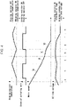
- FIG. 4 is an exemplary diagram illustrating on/off control of a braking resistor according to an embodiment of the present disclosure.
- the main controller 40 transmits, to the switching controller 50, a control signal for controlling the switching unit 60 to be turned on, and the switching controller 50 is switched to the ON state according to the control signal.
- the DC link voltage may decrease and the temperature of the braking resistor 70 may rise.
- the main controller 40 transmits, to the switching controller 50, a control signal for controlling the switching unit 60 to be turned off, and the switching unit 60 switches to the OFF state according to the control signal.
- the voltage, which has decreased in section B may increase again.
- the main controller 40 provides a command frequency of the inverter unit 30 to the switching controller 50 such that the speed reduction rate of the motor 2 is reduced.
- the speed reduction rate 3B in section C is lower than the speed reduction rate 3A in section B.
- the speed reduction rate ratio 3B is determined based on the DC link voltage fed back from the inverter unit 30.
- the main controller 40 does not reach a braking resistor ON reference temperature although the braking resistor 70 is off.
- the speed reduction rate of the motor 2 is lowered over the speed reduction rate in section C, a command frequency for maintaining the DC link voltage at the reference voltage of the braking resistor is generated and provided to the switching controller 50. That is, the speed reduction rate 3C in section D is lower than the speed reduction rate 3B in section C.
- the speed reduction rate 3C is determined based on the DC link voltage fed back from the inverter unit 30.
- the main controller 40 transmits, to the switching controller 50, a control signal for controlling the switching unit 60 to be turned on, and the switching unit 60 switches to the ON state according to the control signal.
- the speed reduction rate 3D of the speed of the motor is equal to the speed reduction rate 3A in section B.
- the main controller 40 changes the command frequency to increase the speed reduction rate of the motor 2 and provides the changed command frequency to the switching controller 50.
- section F the motor 2 is stopped, but the main controller 40 may maintain the braking resistor 70 in the ON state because the DC link voltage is greater than the braking resistor OFF reference voltage.
- the main controller 40 may transmit, to the switching controller 50, a control signal for controlling the switching unit 60 to be turned off, and the switching unit 60 may switch to the OFF state according to the control signal.
- the temperature of the braking resistor 70 is measured or estimated, and the braking resistor 70 is turned on or off according to the temperature of the braking resistor 70.
- the braking resistor 70 may be efficiently used.
- the braking resistor 70 can be used easily even if the usage rate of the braking resistor is not preset.
- the braking resistor 70 can be prevented from overheating due to erroneously setting of the usage rate of the braking resistor.
Landscapes
- Engineering & Computer Science (AREA)
- Power Engineering (AREA)
- Inverter Devices (AREA)
- Stopping Of Electric Motors (AREA)
- Control Of Motors That Do Not Use Commutators (AREA)
- Valve Device For Special Equipments (AREA)
- Control Of Ac Motors In General (AREA)
Claims (2)
- Vorrichtung zum Steuern eines Motors, wobei die Vorrichtung eine Wandlereinheit (10) zum Umwandeln einer elektrischen Netzleistung in eine Gleichspannung (DC-Spannung), einen Gleichstromzwischenkreiskondensator zum Speichern der Gleichspannung und eine Wechselrichtereinheit (30) zum Umwandeln der Gleichspannung in eine Wechselspannung (AC-Spannung) mit einer vorbestimmten Frequenz umfasst, wobei die Vorrichtung ferner umfasst:einen Bremswiderstand (70), der mit demGleichstromzwischenkreiskondensator parallel geschaltet ist;eine Schalteinheit (60) mit einem EIN-Zustand oder einem AUS-Zustand, wobei, wenn sich die Schalteinheit (60) in dem EIN-Zustand befindet, die in demGleichstromzwischenkreiskondensator gespeicherte Gleichspannung durch den Bremswiderstand verbraucht wird; undeine Steuerung (40) zum Übertragen eines Steuersignals, um die Schalteinheit (60) basierend auf zumindest einer von einer Temperatur und einerGleichstromzwischenkreisspannung des Bremswiderstands in den EIN-Zustand oder den AUS-Zustand zu schalten,wobei, wenn die Gleichstromzwischenkreisspannung eine EIN-Referenzspannung erreicht, indem der Motor mit einer ersten Drehzahlreduktionsrate abbremst, während die Temperatur des Bremswiderstands zu einem ersten Zeitpunkt niedriger als eine AUS-Referenztemperatur ist, die Steuerung (40) konfiguriert ist, ein Steuersignal an die Schalteinheit (60) zu senden, um die Schalteinheit (60) in den EIN-Zustand zu schalten,wobei, wenn die Temperatur des Bremswiderstands (70) eine AUS-Referenztemperatur zu einem zweiten Zeitpunkt nach dem ersten Zeitpunkt erreicht, die Steuerung (40) konfiguriert ist:ein Steuersignal an die Schalteinheit (60) zu senden, um die Schalteinheit (60) in den AUS-Zustand zu schalten; unddie Wechselrichtereinheit (30) so zu steuern, dass sie den Motor auf eine zweite Drehzahlreduktionsrate einstellt, die niedriger als die ersteDrehzahlreduktionsrate ist, dadurch gekennzeichnet, dass die Steuerung (40) ferner konfiguriert ist:
wenn die Gleichstromzwischenkreisspannung die EIN-Referenzspannung erreicht, während die Temperatur des Bremswiderstands (70) niedriger als die AUS-Referenztemperatur und höher als eine EIN-Referenztemperatur zu einem dritten Zeitpunkt nach dem zweiten Zeitpunkt ist, die Wechselrichtereinheit (30) so zu steuern, dass sie den Motor auf eine dritte Drehzahlreduktionsrate einstellt, die niedriger als die erste Drehzahlreduktionsrate und die zweite Drehzahlreduktionsrate ist, um die Gleichstromzwischenkreisspannung auf der EIN-Referenzspannung zu halten, undwenn die Temperatur des Bremswiderstands (70) die EIN-Referenztemperatur erreicht, während die Gleichstromzwischenkreisspannung zu einem vierten Zeitpunkt nach dem dritten Zeitpunkt auf der EIN-Referenzspannung gehalten wird, ein Steuersignal an die Schalteinheit (60) zu senden, um die Schalteinheit (60) in den EIN-Zustand zu schalten, sodass die in dem Gleichstromzwischenkreiskondensator gespeicherte Gleichspannung durch den Bremswiderstand verbraucht wird, und die Wechselrichtereinheit so zu steuern, dass sie den Motor mit der ersten Drehzahlreduktionsrate zu dem vierten Zeitpunkt abbremst,wenn die Gleichstromzwischenkreisspannung eine AUS-Referenzspannung zu einem fünften Zeitpunkt nach dem vierten Zeitpunkt erreicht, ein Steuersignal an dieSchalteinheit (60) zu senden, um die Schalteinheit in den AUS-Zustand zu schalten,wobei die zweite und die dritte Drehzahlreduktionsrate basierend auf der von der Wechselrichtereinheit (30) zurückgeführten Gleichstromzwischenkreisspannung bestimmt werden. - Vorrichtung nach Anspruch 1, wobei die Steuerung (40) konfiguriert ist, den EIN-Zustand des Bremswiderstands beizubehalten, nachdem der Motor vor dem fünften Zeitpunkt, aber nach dem vierten Zeitpunkt gestoppt wurde.
Applications Claiming Priority (1)
| Application Number | Priority Date | Filing Date | Title |
|---|---|---|---|
| KR1020170014323A KR102684521B1 (ko) | 2017-02-01 | 2017-02-01 | 인버터 제어장치 |
Publications (2)
| Publication Number | Publication Date |
|---|---|
| EP3358729A1 EP3358729A1 (de) | 2018-08-08 |
| EP3358729B1 true EP3358729B1 (de) | 2022-07-06 |
Family
ID=60654776
Family Applications (1)
| Application Number | Title | Priority Date | Filing Date |
|---|---|---|---|
| EP17206136.8A Active EP3358729B1 (de) | 2017-02-01 | 2017-12-08 | Vorrichtung zur steuerung eines motors |
Country Status (6)
| Country | Link |
|---|---|
| US (1) | US10298155B2 (de) |
| EP (1) | EP3358729B1 (de) |
| JP (1) | JP6580663B2 (de) |
| KR (1) | KR102684521B1 (de) |
| CN (1) | CN108390551B (de) |
| ES (1) | ES2925943T3 (de) |
Cited By (1)
| Publication number | Priority date | Publication date | Assignee | Title |
|---|---|---|---|---|
| WO2025111082A1 (en) * | 2023-11-20 | 2025-05-30 | Caterpillar Inc. | Temperature based resistive braking capacity |
Families Citing this family (3)
| Publication number | Priority date | Publication date | Assignee | Title |
|---|---|---|---|---|
| US11750139B2 (en) * | 2019-07-18 | 2023-09-05 | Sew-Eurodrive Gmbh & Co. Kg | Method and system for operating a system including an energy storage device and resistor |
| EP4329181A1 (de) * | 2022-08-22 | 2024-02-28 | Siemens Aktiengesellschaft | Modularer bremssteller mit hybridem aufbau |
| KR102696219B1 (ko) * | 2024-05-09 | 2024-08-20 | 한화시스템 주식회사 | 다기능 레이다에서 가변 듀티를 가지는 회생 제동 시스템 및 그 방법 |
Family Cites Families (11)
| Publication number | Priority date | Publication date | Assignee | Title |
|---|---|---|---|---|
| JPS6017100B2 (ja) * | 1980-07-21 | 1985-05-01 | コニカ株式会社 | 陰画像形成方法 |
| JPS59195994U (ja) * | 1983-06-14 | 1984-12-26 | 株式会社東芝 | 電動機の速度制御装置 |
| JPS62277081A (ja) * | 1986-05-21 | 1987-12-01 | Mitsubishi Electric Corp | インバ−タ装置 |
| JP3623328B2 (ja) | 1996-10-29 | 2005-02-23 | 東洋電機製造株式会社 | 回生制動装置の過熱保護装置 |
| KR100547336B1 (ko) | 1999-10-13 | 2006-01-26 | 엘지전자 주식회사 | 세탁기에서의 제동 제어방법 |
| JP4062967B2 (ja) * | 2002-05-17 | 2008-03-19 | 富士電機機器制御株式会社 | 抵抗器の過熱保護方法 |
| JP2005253213A (ja) * | 2004-03-04 | 2005-09-15 | Yaskawa Electric Corp | 多軸モータ制御方法および装置 |
| JP5753770B2 (ja) * | 2011-03-30 | 2015-07-22 | 株式会社日立産機システム | 電力変換装置 |
| JP5876681B2 (ja) | 2011-07-20 | 2016-03-02 | 東芝三菱電機産業システム株式会社 | 船舶用ドライブ装置及び当該装置用制動抵抗器の保護方法 |
| CN107836077B (zh) * | 2015-07-09 | 2020-07-07 | 三菱电机株式会社 | 电动机控制装置 |
| JP2018007334A (ja) * | 2016-06-28 | 2018-01-11 | 東芝シュネデール・インバータ株式会社 | 電動機駆動装置 |
-
2017
- 2017-02-01 KR KR1020170014323A patent/KR102684521B1/ko active Active
- 2017-12-08 EP EP17206136.8A patent/EP3358729B1/de active Active
- 2017-12-08 ES ES17206136T patent/ES2925943T3/es active Active
- 2017-12-18 JP JP2017242004A patent/JP6580663B2/ja not_active Expired - Fee Related
- 2017-12-19 CN CN201711375219.XA patent/CN108390551B/zh active Active
- 2017-12-19 US US15/847,232 patent/US10298155B2/en active Active
Non-Patent Citations (1)
| Title |
|---|
| MOGHIMI R: "Curing comparator instability with hysteresis", ANALOG DIALOGUE, ANALOG DEVICES, NORWOOD, MA, US, vol. 34, no. 7, 1 November 2000 (2000-11-01), pages 3pp, XP002386469, ISSN: 0161-3626 * |
Cited By (2)
| Publication number | Priority date | Publication date | Assignee | Title |
|---|---|---|---|---|
| WO2025111082A1 (en) * | 2023-11-20 | 2025-05-30 | Caterpillar Inc. | Temperature based resistive braking capacity |
| US12594834B2 (en) | 2023-11-20 | 2026-04-07 | Caterpillar Inc. | Temperature based resistive braking capacity |
Also Published As
| Publication number | Publication date |
|---|---|
| US10298155B2 (en) | 2019-05-21 |
| CN108390551A (zh) | 2018-08-10 |
| JP2018126050A (ja) | 2018-08-09 |
| KR102684521B1 (ko) | 2024-07-11 |
| ES2925943T3 (es) | 2022-10-20 |
| JP6580663B2 (ja) | 2019-09-25 |
| US20180219496A1 (en) | 2018-08-02 |
| KR20180089681A (ko) | 2018-08-09 |
| EP3358729A1 (de) | 2018-08-08 |
| CN108390551B (zh) | 2020-09-15 |
Similar Documents
| Publication | Publication Date | Title |
|---|---|---|
| EP3358729B1 (de) | Vorrichtung zur steuerung eines motors | |
| US9515581B2 (en) | Motor control device | |
| CN104718102B (zh) | 降额车辆电气驱动马达和发电机部件 | |
| US6439347B2 (en) | Elevator control apparatus controlling charging of a power source with regenerative power | |
| EP1626491A2 (de) | Wandlervorrichtung, Wechselrichtervorrichtung und Zwischenkreisgleichspannungssteuerverfahren | |
| US10153720B2 (en) | Power supply system for electric vehicle | |
| EP2320556A2 (de) | Leistungskonvertereinrichtung | |
| JP5753770B2 (ja) | 電力変換装置 | |
| CA2862146C (en) | Drive system with energy accumulator and method for operating a drive system | |
| US9988135B2 (en) | System for controlling an electrical power system | |
| EP3110000B1 (de) | Steuerungsvorrichtung | |
| EP2320555A2 (de) | Motorsteuerungsvorrichtung | |
| ES2900245T3 (es) | Inversor | |
| EP3845478B1 (de) | Aufzuggeschwindigkeitsüberwachung | |
| US20140035507A1 (en) | Motor deceleration method and motor driving apparatus applying the motor deceleration method | |
| WO2004082123A1 (ja) | 交流電動機の制御方法及び制御装置 | |
| KR101750609B1 (ko) | 부하적응형 부스트 전압을 제공하는 인버터 | |
| JP2018007334A (ja) | 電動機駆動装置 | |
| US20190100113A1 (en) | Electric vehicle | |
| JP7096699B2 (ja) | 電力変換装置 | |
| KR102079527B1 (ko) | 인버터 제어장치 | |
| KR20250177818A (ko) | 회생 저항의 보호 방법 및 모터 제어 장치 | |
| JPH09247978A (ja) | 電動機駆動用電源装置 | |
| EP3168978A1 (de) | Energieerzeugungssteuerungsvorrichtung für wechselstromgenerator eines fahrzeugs |
Legal Events
| Date | Code | Title | Description |
|---|---|---|---|
| PUAI | Public reference made under article 153(3) epc to a published international application that has entered the european phase |
Free format text: ORIGINAL CODE: 0009012 |
|
| STAA | Information on the status of an ep patent application or granted ep patent |
Free format text: STATUS: THE APPLICATION HAS BEEN PUBLISHED |
|
| AK | Designated contracting states |
Kind code of ref document: A1 Designated state(s): AL AT BE BG CH CY CZ DE DK EE ES FI FR GB GR HR HU IE IS IT LI LT LU LV MC MK MT NL NO PL PT RO RS SE SI SK SM TR |
|
| AX | Request for extension of the european patent |
Extension state: BA ME |
|
| STAA | Information on the status of an ep patent application or granted ep patent |
Free format text: STATUS: REQUEST FOR EXAMINATION WAS MADE |
|
| 17P | Request for examination filed |
Effective date: 20190204 |
|
| RBV | Designated contracting states (corrected) |
Designated state(s): AL AT BE BG CH CY CZ DE DK EE ES FI FR GB GR HR HU IE IS IT LI LT LU LV MC MK MT NL NO PL PT RO RS SE SI SK SM TR |
|
| STAA | Information on the status of an ep patent application or granted ep patent |
Free format text: STATUS: EXAMINATION IS IN PROGRESS |
|
| 17Q | First examination report despatched |
Effective date: 20191111 |
|
| GRAP | Despatch of communication of intention to grant a patent |
Free format text: ORIGINAL CODE: EPIDOSNIGR1 |
|
| STAA | Information on the status of an ep patent application or granted ep patent |
Free format text: STATUS: GRANT OF PATENT IS INTENDED |
|
| RIC1 | Information provided on ipc code assigned before grant |
Ipc: H02M 7/5387 20070101ALN20220324BHEP Ipc: H02P 29/68 20160101ALI20220324BHEP Ipc: H02P 3/22 20060101ALI20220324BHEP Ipc: H02M 1/32 20070101AFI20220324BHEP |
|
| INTG | Intention to grant announced |
Effective date: 20220407 |
|
| GRAS | Grant fee paid |
Free format text: ORIGINAL CODE: EPIDOSNIGR3 |
|
| GRAA | (expected) grant |
Free format text: ORIGINAL CODE: 0009210 |
|
| STAA | Information on the status of an ep patent application or granted ep patent |
Free format text: STATUS: THE PATENT HAS BEEN GRANTED |
|
| AK | Designated contracting states |
Kind code of ref document: B1 Designated state(s): AL AT BE BG CH CY CZ DE DK EE ES FI FR GB GR HR HU IE IS IT LI LT LU LV MC MK MT NL NO PL PT RO RS SE SI SK SM TR |
|
| REG | Reference to a national code |
Ref country code: AT Ref legal event code: REF Ref document number: 1503589 Country of ref document: AT Kind code of ref document: T Effective date: 20220715 Ref country code: CH Ref legal event code: EP |
|
| REG | Reference to a national code |
Ref country code: DE Ref legal event code: R096 Ref document number: 602017059186 Country of ref document: DE |
|
| REG | Reference to a national code |
Ref country code: IE Ref legal event code: FG4D |
|
| REG | Reference to a national code |
Ref country code: ES Ref legal event code: FG2A Ref document number: 2925943 Country of ref document: ES Kind code of ref document: T3 Effective date: 20221020 |
|
| REG | Reference to a national code |
Ref country code: LT Ref legal event code: MG9D |
|
| REG | Reference to a national code |
Ref country code: NL Ref legal event code: MP Effective date: 20220706 |
|
| PG25 | Lapsed in a contracting state [announced via postgrant information from national office to epo] |
Ref country code: SE Free format text: LAPSE BECAUSE OF FAILURE TO SUBMIT A TRANSLATION OF THE DESCRIPTION OR TO PAY THE FEE WITHIN THE PRESCRIBED TIME-LIMIT Effective date: 20220706 Ref country code: RS Free format text: LAPSE BECAUSE OF FAILURE TO SUBMIT A TRANSLATION OF THE DESCRIPTION OR TO PAY THE FEE WITHIN THE PRESCRIBED TIME-LIMIT Effective date: 20220706 Ref country code: PT Free format text: LAPSE BECAUSE OF FAILURE TO SUBMIT A TRANSLATION OF THE DESCRIPTION OR TO PAY THE FEE WITHIN THE PRESCRIBED TIME-LIMIT Effective date: 20221107 Ref country code: NO Free format text: LAPSE BECAUSE OF FAILURE TO SUBMIT A TRANSLATION OF THE DESCRIPTION OR TO PAY THE FEE WITHIN THE PRESCRIBED TIME-LIMIT Effective date: 20221006 Ref country code: NL Free format text: LAPSE BECAUSE OF FAILURE TO SUBMIT A TRANSLATION OF THE DESCRIPTION OR TO PAY THE FEE WITHIN THE PRESCRIBED TIME-LIMIT Effective date: 20220706 Ref country code: LV Free format text: LAPSE BECAUSE OF FAILURE TO SUBMIT A TRANSLATION OF THE DESCRIPTION OR TO PAY THE FEE WITHIN THE PRESCRIBED TIME-LIMIT Effective date: 20220706 Ref country code: LT Free format text: LAPSE BECAUSE OF FAILURE TO SUBMIT A TRANSLATION OF THE DESCRIPTION OR TO PAY THE FEE WITHIN THE PRESCRIBED TIME-LIMIT Effective date: 20220706 Ref country code: FI Free format text: LAPSE BECAUSE OF FAILURE TO SUBMIT A TRANSLATION OF THE DESCRIPTION OR TO PAY THE FEE WITHIN THE PRESCRIBED TIME-LIMIT Effective date: 20220706 |
|
| PGFP | Annual fee paid to national office [announced via postgrant information from national office to epo] |
Ref country code: GB Payment date: 20221121 Year of fee payment: 6 |
|
| REG | Reference to a national code |
Ref country code: AT Ref legal event code: MK05 Ref document number: 1503589 Country of ref document: AT Kind code of ref document: T Effective date: 20220706 |
|
| PG25 | Lapsed in a contracting state [announced via postgrant information from national office to epo] |
Ref country code: PL Free format text: LAPSE BECAUSE OF FAILURE TO SUBMIT A TRANSLATION OF THE DESCRIPTION OR TO PAY THE FEE WITHIN THE PRESCRIBED TIME-LIMIT Effective date: 20220706 Ref country code: IS Free format text: LAPSE BECAUSE OF FAILURE TO SUBMIT A TRANSLATION OF THE DESCRIPTION OR TO PAY THE FEE WITHIN THE PRESCRIBED TIME-LIMIT Effective date: 20221106 Ref country code: HR Free format text: LAPSE BECAUSE OF FAILURE TO SUBMIT A TRANSLATION OF THE DESCRIPTION OR TO PAY THE FEE WITHIN THE PRESCRIBED TIME-LIMIT Effective date: 20220706 Ref country code: GR Free format text: LAPSE BECAUSE OF FAILURE TO SUBMIT A TRANSLATION OF THE DESCRIPTION OR TO PAY THE FEE WITHIN THE PRESCRIBED TIME-LIMIT Effective date: 20221007 |
|
| REG | Reference to a national code |
Ref country code: DE Ref legal event code: R097 Ref document number: 602017059186 Country of ref document: DE |
|
| PG25 | Lapsed in a contracting state [announced via postgrant information from national office to epo] |
Ref country code: SM Free format text: LAPSE BECAUSE OF FAILURE TO SUBMIT A TRANSLATION OF THE DESCRIPTION OR TO PAY THE FEE WITHIN THE PRESCRIBED TIME-LIMIT Effective date: 20220706 Ref country code: RO Free format text: LAPSE BECAUSE OF FAILURE TO SUBMIT A TRANSLATION OF THE DESCRIPTION OR TO PAY THE FEE WITHIN THE PRESCRIBED TIME-LIMIT Effective date: 20220706 Ref country code: DK Free format text: LAPSE BECAUSE OF FAILURE TO SUBMIT A TRANSLATION OF THE DESCRIPTION OR TO PAY THE FEE WITHIN THE PRESCRIBED TIME-LIMIT Effective date: 20220706 Ref country code: CZ Free format text: LAPSE BECAUSE OF FAILURE TO SUBMIT A TRANSLATION OF THE DESCRIPTION OR TO PAY THE FEE WITHIN THE PRESCRIBED TIME-LIMIT Effective date: 20220706 Ref country code: AT Free format text: LAPSE BECAUSE OF FAILURE TO SUBMIT A TRANSLATION OF THE DESCRIPTION OR TO PAY THE FEE WITHIN THE PRESCRIBED TIME-LIMIT Effective date: 20220706 |
|
| PGFP | Annual fee paid to national office [announced via postgrant information from national office to epo] |
Ref country code: ES Payment date: 20230113 Year of fee payment: 6 |
|
| PLBE | No opposition filed within time limit |
Free format text: ORIGINAL CODE: 0009261 |
|
| STAA | Information on the status of an ep patent application or granted ep patent |
Free format text: STATUS: NO OPPOSITION FILED WITHIN TIME LIMIT |
|
| PG25 | Lapsed in a contracting state [announced via postgrant information from national office to epo] |
Ref country code: SK Free format text: LAPSE BECAUSE OF FAILURE TO SUBMIT A TRANSLATION OF THE DESCRIPTION OR TO PAY THE FEE WITHIN THE PRESCRIBED TIME-LIMIT Effective date: 20220706 Ref country code: EE Free format text: LAPSE BECAUSE OF FAILURE TO SUBMIT A TRANSLATION OF THE DESCRIPTION OR TO PAY THE FEE WITHIN THE PRESCRIBED TIME-LIMIT Effective date: 20220706 |
|
| 26N | No opposition filed |
Effective date: 20230411 |
|
| PG25 | Lapsed in a contracting state [announced via postgrant information from national office to epo] |
Ref country code: AL Free format text: LAPSE BECAUSE OF FAILURE TO SUBMIT A TRANSLATION OF THE DESCRIPTION OR TO PAY THE FEE WITHIN THE PRESCRIBED TIME-LIMIT Effective date: 20220706 |
|
| REG | Reference to a national code |
Ref country code: CH Ref legal event code: PL |
|
| P01 | Opt-out of the competence of the unified patent court (upc) registered |
Effective date: 20230625 |
|
| REG | Reference to a national code |
Ref country code: BE Ref legal event code: MM Effective date: 20221231 |
|
| PG25 | Lapsed in a contracting state [announced via postgrant information from national office to epo] |
Ref country code: SI Free format text: LAPSE BECAUSE OF FAILURE TO SUBMIT A TRANSLATION OF THE DESCRIPTION OR TO PAY THE FEE WITHIN THE PRESCRIBED TIME-LIMIT Effective date: 20220706 Ref country code: LU Free format text: LAPSE BECAUSE OF NON-PAYMENT OF DUE FEES Effective date: 20221208 |
|
| PG25 | Lapsed in a contracting state [announced via postgrant information from national office to epo] |
Ref country code: LI Free format text: LAPSE BECAUSE OF NON-PAYMENT OF DUE FEES Effective date: 20221231 Ref country code: IE Free format text: LAPSE BECAUSE OF NON-PAYMENT OF DUE FEES Effective date: 20221208 Ref country code: CH Free format text: LAPSE BECAUSE OF NON-PAYMENT OF DUE FEES Effective date: 20221231 |
|
| PG25 | Lapsed in a contracting state [announced via postgrant information from national office to epo] |
Ref country code: FR Free format text: LAPSE BECAUSE OF NON-PAYMENT OF DUE FEES Effective date: 20221231 Ref country code: BE Free format text: LAPSE BECAUSE OF NON-PAYMENT OF DUE FEES Effective date: 20221231 |
|
| PG25 | Lapsed in a contracting state [announced via postgrant information from national office to epo] |
Ref country code: HU Free format text: LAPSE BECAUSE OF FAILURE TO SUBMIT A TRANSLATION OF THE DESCRIPTION OR TO PAY THE FEE WITHIN THE PRESCRIBED TIME-LIMIT; INVALID AB INITIO Effective date: 20171208 |
|
| PG25 | Lapsed in a contracting state [announced via postgrant information from national office to epo] |
Ref country code: CY Free format text: LAPSE BECAUSE OF FAILURE TO SUBMIT A TRANSLATION OF THE DESCRIPTION OR TO PAY THE FEE WITHIN THE PRESCRIBED TIME-LIMIT Effective date: 20220706 |
|
| PG25 | Lapsed in a contracting state [announced via postgrant information from national office to epo] |
Ref country code: MK Free format text: LAPSE BECAUSE OF FAILURE TO SUBMIT A TRANSLATION OF THE DESCRIPTION OR TO PAY THE FEE WITHIN THE PRESCRIBED TIME-LIMIT Effective date: 20220706 |
|
| PG25 | Lapsed in a contracting state [announced via postgrant information from national office to epo] |
Ref country code: MC Free format text: LAPSE BECAUSE OF FAILURE TO SUBMIT A TRANSLATION OF THE DESCRIPTION OR TO PAY THE FEE WITHIN THE PRESCRIBED TIME-LIMIT Effective date: 20220706 |
|
| PG25 | Lapsed in a contracting state [announced via postgrant information from national office to epo] |
Ref country code: MC Free format text: LAPSE BECAUSE OF FAILURE TO SUBMIT A TRANSLATION OF THE DESCRIPTION OR TO PAY THE FEE WITHIN THE PRESCRIBED TIME-LIMIT Effective date: 20220706 |
|
| PG25 | Lapsed in a contracting state [announced via postgrant information from national office to epo] |
Ref country code: BG Free format text: LAPSE BECAUSE OF FAILURE TO SUBMIT A TRANSLATION OF THE DESCRIPTION OR TO PAY THE FEE WITHIN THE PRESCRIBED TIME-LIMIT Effective date: 20220706 |
|
| GBPC | Gb: european patent ceased through non-payment of renewal fee |
Effective date: 20231208 |
|
| PG25 | Lapsed in a contracting state [announced via postgrant information from national office to epo] |
Ref country code: MT Free format text: LAPSE BECAUSE OF FAILURE TO SUBMIT A TRANSLATION OF THE DESCRIPTION OR TO PAY THE FEE WITHIN THE PRESCRIBED TIME-LIMIT Effective date: 20220706 |
|
| PG25 | Lapsed in a contracting state [announced via postgrant information from national office to epo] |
Ref country code: GB Free format text: LAPSE BECAUSE OF NON-PAYMENT OF DUE FEES Effective date: 20231208 |
|
| PG25 | Lapsed in a contracting state [announced via postgrant information from national office to epo] |
Ref country code: GB Free format text: LAPSE BECAUSE OF NON-PAYMENT OF DUE FEES Effective date: 20231208 |
|
| REG | Reference to a national code |
Ref country code: ES Ref legal event code: FD2A Effective date: 20250124 |
|
| PG25 | Lapsed in a contracting state [announced via postgrant information from national office to epo] |
Ref country code: ES Free format text: LAPSE BECAUSE OF NON-PAYMENT OF DUE FEES Effective date: 20231209 |
|
| PGFP | Annual fee paid to national office [announced via postgrant information from national office to epo] |
Ref country code: IT Payment date: 20250909 Year of fee payment: 9 |
|
| PG25 | Lapsed in a contracting state [announced via postgrant information from national office to epo] |
Ref country code: TR Free format text: LAPSE BECAUSE OF FAILURE TO SUBMIT A TRANSLATION OF THE DESCRIPTION OR TO PAY THE FEE WITHIN THE PRESCRIBED TIME-LIMIT Effective date: 20220706 |
|
| PGFP | Annual fee paid to national office [announced via postgrant information from national office to epo] |
Ref country code: DE Payment date: 20250908 Year of fee payment: 9 |