EP3358743A1 - Stromumwandlungsvorrichtung und automatisches einstellverfahren dafür - Google Patents
Stromumwandlungsvorrichtung und automatisches einstellverfahren dafür Download PDFInfo
- Publication number
- EP3358743A1 EP3358743A1 EP16850826.5A EP16850826A EP3358743A1 EP 3358743 A1 EP3358743 A1 EP 3358743A1 EP 16850826 A EP16850826 A EP 16850826A EP 3358743 A1 EP3358743 A1 EP 3358743A1
- Authority
- EP
- European Patent Office
- Prior art keywords
- value
- command value
- magnetic flux
- mutual inductance
- current
- Prior art date
- Legal status (The legal status is an assumption and is not a legal conclusion. Google has not performed a legal analysis and makes no representation as to the accuracy of the status listed.)
- Granted
Links
Images


Classifications
-
- H—ELECTRICITY
- H02—GENERATION; CONVERSION OR DISTRIBUTION OF ELECTRIC POWER
- H02P—CONTROL OR REGULATION OF ELECTRIC MOTORS, ELECTRIC GENERATORS OR DYNAMO-ELECTRIC CONVERTERS; CONTROLLING TRANSFORMERS, REACTORS OR CHOKE COILS
- H02P21/00—Arrangements or methods for the control of electric machines by vector control, e.g. by control of field orientation
- H02P21/14—Estimation or adaptation of machine parameters, e.g. flux, current or voltage
-
- H—ELECTRICITY
- H02—GENERATION; CONVERSION OR DISTRIBUTION OF ELECTRIC POWER
- H02P—CONTROL OR REGULATION OF ELECTRIC MOTORS, ELECTRIC GENERATORS OR DYNAMO-ELECTRIC CONVERTERS; CONTROLLING TRANSFORMERS, REACTORS OR CHOKE COILS
- H02P27/00—Arrangements or methods for the control of AC motors characterised by the kind of supply voltage
- H02P27/04—Arrangements or methods for the control of AC motors characterised by the kind of supply voltage using variable-frequency supply voltage, e.g. inverter or converter supply voltage
- H02P27/047—V/F converter, wherein the voltage is controlled proportionally with the frequency
Definitions
- the present invention relates to a power conversion apparatus that drives an induction motor and a method of automatically tuning the power conversion apparatus.
- an induction motor for a certain application, it is required to output high torque in a low speed range such as, for example, 5 Hz or less, and in order to solve a torque shortage in a low speed range, an excitation current is increased.
- increasing the excitation current generates magnetic flux saturation, it is difficult to set a numerical value that represents appropriate motor characteristics in vector control. For this reason, it is necessary to set an appropriate magnetic flux command in consideration of magnetic flux saturation in the power conversion apparatus that drives the induction motor.
- PTL 1 describes techniques such as a technique capable of measuring an excitation current equivalent to an excitation current in an equivalent no-load test, even under a load condition in an equivalent no-load test method of an induction machine, and a control technique that limits a voltage boost amount using torque measurement when overcurrent limitation is applied or using this torque.
- PTL 1 describes "an equivalent no-load test method of an induction machine in a case where there are known a primary resistance and an equivalent leakage inductance of the induction machine of a system that uses an inverter to start the induction machine, the equivalent no-load test method comprising a function of separating an excitation current component from a primary current vector, the primary resistance, and the equivalent leakage inductance of the induction machine, by an estimation calculation based on a circle diagram method, the function being capable of separating an excitation current component even at the time of a load.” (claim 1).
- An example of a method of automatically tuning a power conversion apparatus of the present invention is a method of automatically tuning a power conversion apparatus that drives an induction motor.
- the method of automatically tuning the power conversion apparatus includes, in an auto tuning mode, a step in which an V/f control unit that outputs a voltage command value of the induction motor changes the ratio of an output voltage of the induction motor to an output frequency of the induction motor to change a voltage command value over several stages, a step in which a current detecting means detects an excitation current that changes in several stages, and a step in which a mutual inductance calculation unit calculates reactive power on the basis of the voltage command value, a current detection value, and a speed command value, and estimates, from the reactive power, a mutual inductance of the induction motor that changes in several stages.
- An example of the power conversion apparatus of the present invention is a power conversion apparatus that drives an induction motor.
- the power conversion apparatus includes a current detecting means that detects a driving current of the induction motor, an A V/f control unit that outputs a voltage command value of the induction motor on the basis of a speed command value of the induction motor, a ratio of an output voltage of the induction motor to an output frequency of the induction motor, and a mutual inductance calculation unit that calculates a mutual inductance of the induction motor on the basis of the voltage command value, a current detection value, and a speed command value.
- the mutual inductance calculation unit includes a reactive power calculation unit that calculates reactive power on the basis of the voltage command value, the current detection value, and the speed command value, and a mutual inductance estimation unit that estimates a mutual inductance from the calculated reactive power.
- the power conversion apparatus includes a magnetic flux axis current/magnetic flux command setting unit that outputs a current command value and a secondary magnetic flux command value on the basis of a set mutual inductance value and a set excitation current value, and a vector control calculation unit that outputs a voltage command value of the induction motor on the basis of the current command value and the secondary magnetic flux command value.
- the magnetic flux axis current/magnetic flux command setting unit sets a mutual inductance value in a saturated state and an excitation current value at that time in a low speed range, and sets a mutual inductance value in a normal state and an excitation current value at that time in a middle and high speed range.
- the first embodiment relates to measurement of a mutual inductance M in consideration of magnetic saturation by V/f control.
- FIG. 1 illustrates a configuration diagram of a power conversion apparatus according to the first embodiment of the present invention.
- An induction motor 1 generates torque by magnetic flux generated by a current of a magnetic flux axis (d-axis) component and a current of a torque axis (q-axis) component orthogonal to the magnetic flux axis.
- a power converter 2 outputs a voltage value proportional to voltage command values V u *, V v *, and V w * of a three-phase alternating current and varies an output voltage value and a rotational frequency value of the induction motor 1.
- a direct current power supply 2a supplies a direct current voltage to the power converter 2.
- a current detector 3 outputs detected values I uc , I vc , and I wc of three-phase alternating currents I u , I v , and I w of the induction motor 1.
- a coordinate conversion unit 4 outputs a d-axis current detection value I dc , and a q-axis current detection value I qc of the rotational coordinate axes from the detected values I uc , I vc , and I wc of the three-phase alternating currents I u , I v , and I w and a phase estimated value ⁇ dc .
- a V/f control unit 5 outputs a d-axis voltage command value V dc * and a q-axis voltage command value V qc * on the basis of a speed command value ⁇ r * and the ratio of the output voltage of the induction motor 1 to the output frequency of the induction motor 1 (V/f).
- a coordinate conversion unit 6 outputs the voltage command values V u *, V v *, and V w * of the three-phase alternating current on the fixed coordinate axes from the voltage command values V dc * and V qc * and the phase estimated value ⁇ dc .
- a mutual inductance calculation unit 7 calculates a mutual inductance M ⁇ of the induction motor 1 on the basis of the d-axis voltage command value V dc * and the q-axis voltage command value V qc *, the d-axis current detection value I dc , the q-axis current detection value I qc , the speed command value ⁇ r *, and a leakage inductance L ⁇ of the induction motor 1.
- a phase estimation calculation unit 8 integrates the speed command value ⁇ r * and outputs the phase estimated value ⁇ dc .
- a V/f control unit 5 multiplies the speed command value ⁇ r * given from a host device by the ratio of the output voltage of the induction motor 1 to the output frequency of the induction motor 1 (V/f_gain) and calculates a q-axis voltage command value V qc * by a calculation illustrated in (Equation 1).
- a drop voltage by a primary resistance R 1 of the induction motor 1 is not compensated.
- a boost operation that gives the above-described voltage drop as a voltage bias to the voltage command values V dc * and V qc *. In particular, this is effective in a case where load torque is applied from the time of startup.
- FIG. 2 illustrates a configuration of the mutual inductance calculation unit 7 that is a feature of the present invention.
- the mutual inductance calculation unit 7 includes a reactive power calculation unit 7a and a mutual inductance estimation unit 7b.
- the reactive power calculation unit 7a calculates reactive power Q ⁇ of the induction motor 1 according to (Equation 2) using the d-axis voltage command value V dc *, the q-axis voltage command value V qc *, the d-axis current detection value I dc , and the q-axis current detection value I qc .
- Q ⁇ V dc * ⁇ I qc ⁇ V qc * ⁇ I dc
- L ⁇ represents a leakage inductance
- M represents a mutual inductance
- L2 represents a secondary side inductance
- ⁇ 1 represents a primary angular frequency command
- ⁇ 2d represents a d-axis secondary magnetic flux
- ⁇ 2q represents a q-axis secondary flux.
- the second embodiment relates to creation of a table of a mutual inductance and an excitation current.
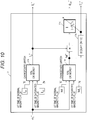
- FIG. 3 is a configuration diagram of a power conversion apparatus according to the second embodiment of the present invention.
- a ratio of an output voltage to an output frequency (hereinafter referred to as V/f ratio) of the V/f control unit is set to a fixed value.
- V/f ratio is changed in several stages.
- reference numerals 1 to 4 and 6 to 8 are the same as those in FIG. 1 .
- FIG. 4 is a configuration diagram of a V/f control unit 5'.
- the V/f control unit 5' sets the V/f ratio (V/f_gain) that changes in several stages to a variable 5'a and multiplies the V/f ratio by the speed command value ⁇ r * to output the q-axis voltage command value V qc *. Furthermore, zero that is set to a constant 5'b is output to the d-axis voltage command value V dc *.
- FIG. 5 illustrates an example of an output signal of the variable 5'a.
- an example in which the output signal of the variable 5'a is changed in five stages is illustrated.
- FIG. 6 illustrates characteristics of the voltage command value and the current detection value in a case where the V/f ratio is changed in five stages (50% loaded state). It can be seen that when the V/f ratio is increased with the speed command value ⁇ r * being a constant value, a d-axis current detection value I dc also increases.
- the d-axis current detection value I dc can also be changed indirectly.
- the q-axis current detection value I qc decreases. This is because the d-axis secondary magnetic flux ⁇ 2d also increases as a d-axis current I d increases.
- the q-axis voltage command value V qc * that has changed in several stages (five stages in the present embodiment), the d-axis current detection value I dc , and the q-axis current detection value I qc are input.
- a mutual inductance/excitation current table unit 9 the mutual inductance estimated value M ⁇ that has changed in several stages and the d-axis current detection value I dc used for calculation at that time are input, and a table relating to the mutual inductance and the excitation current (d-axis current detection value) is created.
- FIG. 7 illustrates an example of the table relating to the mutual inductance and the excitation current.
- the excitation current (d-axis current detection value i dc ) is illustrated on the horizontal axis and the mutual inductance value (estimated value M ⁇ ) is illustrated on the vertical axis.
- the mutual inductance and the excitation current there are (M 1 , I d1 ), (M 2 , I d2 ), and the like.
- FIG. 8 is a configuration diagram of a power conversion apparatus according to the third embodiment of the present invention.
- the first embodiment relates to the estimation of the mutual inductance M
- the second embodiment relates to the creation of the mutual inductance M and the excitation current table.
- the third embodiment is obtained by applying the table created in the second embodiment to a power conversion apparatus controlled by speed sensorless vector control.
- reference numerals 1 to 4, 6, and 8 are the same as those in FIG. 1 .
- a speed estimation calculation unit 10 outputs a speed estimated value ⁇ r ⁇ of an induction motor 1 on the basis of a q-axis voltage command value V qc ***, a q-axis current detection value I qc , an output frequency value ⁇ 1 *, electric constants (R 1 and R 2 ') of the induction motor 1, and a d-axis secondary magnetic flux command value ⁇ 2d * of a d-axis current/magnetic flux command setting unit 13.
- a slip frequency calculation unit 11 outputs a slip frequency command value ⁇ s * of the induction motor 1 on the basis of a d-axis current command value I d *, a q-axis current command value I q * and a set value T 2 * of a secondary time constant that is output of the d-axis current-flux command setting unit 13.
- An adding unit 12 outputs an output frequency value ⁇ 1 * that is an added value of the speed estimated value ⁇ r ⁇ and the slip frequency command value ⁇ s *.
- the d-axis current/magnetic flux command setting unit 13 outputs a d-axis current command value I d *, the d-axis secondary magnetic flux command value ⁇ 2d *, and the set value T 2 * of the secondary time constant from the table of the mutual inductance M and the excitation current that has been created in the second embodiment.
- a speed control calculation unit 14 outputs a q-axis current command value I q * from a deviation between the speed command value ⁇ r * and the speed estimated value ⁇ r ⁇ ⁇ r * - ⁇ r ⁇ ).
- a vector control calculation unit 15 outputs a d-axis voltage reference value V dc ** and a q-axis voltage reference value V qc ** on the basis of electric constants (R 1 and L ⁇ ) of the induction motor 1, the d-axis secondary magnetic flux command value ⁇ 2d * and the current command values I d * and I q * that are output of the d-axis current/magnetic flux command setting unit 13, and the output frequency value ⁇ 1 *.
- a d-axis current control calculation unit 16 outputs a d-axis voltage correction value ⁇ V d * from a deviation (I d * - I dc ) between the d-axis current command value I d * and the d-axis current detection value I dc .
- a q-axis current control calculation unit 17 outputs a q-axis voltage correction value ⁇ V q * from a deviation (I q * - I qc ) between the q-axis current command value I q * and the q-axis current detection value I qc .
- An adding unit 18 outputs a voltage command value V dc *** that is an added value of the d-axis voltage reference value V dc ** and the d-axis voltage correction value ⁇ V d *.
- An adding unit 19 outputs a voltage command value V qc *** that is an added value of the q-axis voltage reference value V qc ** and the q-axis voltage correction value ⁇ V q *.
- the d-axis current/magnetic flux command setting unit 13 (conventional) outputs the current command value I d * necessary for generating the d-axis secondary magnetic flux value ⁇ 2d of the induction motor 1 (uses an excitation current value and a mutual inductance M that are measured at a normal V/f ratio).
- the speed control calculation unit 14 calculates the q-axis current command value I q * so that the speed estimated value ⁇ r ⁇ matches or approaches the speed command value ⁇ r *.
- the vector control calculation unit 15 calculates the voltage reference values V dc ** and V qc ** illustrated in (Equation 6) using the d-axis current command value I d *, the q-axis current command value I q *, electric constants (R 1 , L ⁇ , M, and L2) of the induction motor 1, the d-axis secondary magnetic flux command value ⁇ 2d *, and the output frequency value ⁇ 1 *.
- V dc * * R 1 ⁇ I d * ⁇ ⁇ 1 * ⁇ L ⁇ ⁇ 1 1 + T ACR ⁇ S I q *
- V qc * * R 1 ⁇ I q * + ⁇ 1 * L ⁇ ⁇ 1 1 + T ACR ⁇ S I d * + ⁇ 1 * ⁇ M L 2 ⁇ ⁇ 2 d *
- T ACR represents a current control delay time constant.
- the d-axis current command value I d * and the d-axis current detection value I dc are input.
- the q-axis current control calculation unit 17 the q-axis current command value I q * and the q-axis current detection value I qc are input.
- K pdACR represents a proportional gain of d-axis current control
- K idACR represents an integral gain of the d-axis current control
- K pqACR represents a proportional gain of the q-axis current control
- K iqACR represents an integral gain of the q-axis current control
- the adding units 18 and 19 calculate voltage command values V dc ** and V qc ** illustrated in (Equation 8), and control an output voltage of a power converter 2.
- V dc * * * V dc * * + ⁇ V d *
- V qc * * * V qc * * + ⁇ V q *
- the speed estimation calculation unit 10 estimates a speed of the induction motor 1 according to (Equation 9).
- the speed estimated value ⁇ r ⁇ is calculated by estimating a q-axis induced voltage value by a disturbance observer and dividing by a magnetic flux coefficient.
- ⁇ r ⁇ 1 1 + T obs ⁇ s V qc * * * ⁇ ⁇ 1 * * ⁇ L ⁇ ⁇ 1 1 + T ACR ⁇ S I d * ⁇ R 1 + R 2 ' + L ⁇ ⁇ s ⁇ I qc M L 2 ⁇ 2 d *
- R 2 ' represents a primary side converted value of a secondary resistance value
- T obs represents a speed estimated delay time constant set for the disturbance observer.
- the slip frequency calculation unit 11 calculates the slip frequency command value ⁇ s * of the induction motor 1 according to (Equation 10).
- T 2 * represents a set value of the secondary time constant.
- a sensorless control calculation is executed using, as a control reference, the phase estimated value ⁇ dc that is an estimated value of the phase ⁇ d of the magnetic flux axis.
- FIG. 9 illustrates load operation characteristics (simulation result) in a case where an error of 10% or more is given to a resistance value set for the sensorless control.
- FIG. 10 illustrates a block of the d-axis current/magnetic flux command setting unit 13 (utilizing the second embodiment) according to the embodiment.
- the d-axis current/magnetic flux command setting unit 13 (1) switches and outputs the d-axis current command value I d * and the secondary magnetic flux command value ⁇ 2d *, and (2) switches and outputs the set value T 2 * of the secondary time constant.
- a changeover switch 13a for the d-axis current command value I d * selects I d2 at the time of saturated magnetic flux in a case where the speed command value ⁇ r * is less than 10% of the base frequency, and selects I d1 at the time of normal magnetic flux in a case where the speed command value ⁇ r * is 10% or more of the base frequency.
- a changeover switch 13b for the secondary magnetic flux command value ⁇ 2d * selects M 2 at the time of saturated magnetic flux in a case where the speed command value ⁇ r * is 10% or more of the base frequency, and selects M 1 at the time of normal magnetic flux in a case where the speed command value ⁇ r * is 10% or more of the base frequency.
- the mutual inductance set value M* is multiplied by the d-axis current command value I d *, passed through a low-pass filter 13d having a gain of the secondary time constant set value T 2 * of the induction motor 1, and then outputted as the secondary magnetic flux command value ⁇ 2d *.
- the switching level value of the changeover switches 13a and 13b is set to 10% of the base frequency, but may be 5% or 20%, and may be arbitrarily set.
- constants (I d1 , I d2 , M 1 , and M 2 ) to be set internally in FIG. 10 are set by selecting from the mutual inductance and excitation current table in the second embodiment.
- the excitation current value and the mutual inductance value at the time of normal magnetic flux may be set as I d1 and M 1 , respectively, and the excitation current value and the mutual inductance value at the time of magnetic flux saturation may be set as I d2 and M 2 , respectively.
- data (I d1 , M 1 ) of (1) is selected at the time of normal magnetic flux, and data (I d2 , M 2 ) of (4) at the time of saturated magnetic flux. That is, by driving with the magnetic flux saturation region (using the data in (4)) in the low speed range, a speed control system is stabilized by minimizing an error in speed estimation related to flux fluctuations.
- FIG. 11 illustrates a simulation result of the load operation characteristics according to the present embodiment.
- a load condition used in FIG. 9 is set.
- a comparison between the results of the load characteristics disclosed in FIGS. 9 and 11 shows that in the case of control using the d-axis current/magnetic flux command setting unit 13 that is a feature of the present embodiment, a steady speed deviation of the actual speed value ⁇ r of the induction motor 1 decreases and the speed control system is stable.
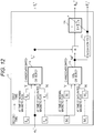
- FIG. 12 is a configuration diagram of a d-axis current/magnetic flux command setting unit 13 according to the fourth embodiment of the present invention.
- the d-axis current command value I d * and the mutual inductance M* that are set in the d-axis current/magnetic flux command setting unit 13 one set of (I d1 , M 1 ) at the time of normal magnetic flux and (I d2 , M 2 ) at the time of saturated magnetic flux is set.
- two sets, each of which includes data at the time of normal magnetic flux and data at the time of saturated magnetic flux are set.
- reference numerals 13a to 13d are the same as those in FIG. 10 .
- the d-axis current/magnetic flux command setting unit 13' sets a total of two sets, each of which includes data at the time of normal magnetic flux and data at the time of saturated magnetic flux are set, that is, one set of (I d1 , M 1 ) at the time of normal magnetic flux and (I d2 , M 2 ) at the time of saturated magnetic flux and one set of (I d3 , M 3 ) at the time of normal magnetic flux and (I d4 , M 4 ) at the time of saturated magnetic flux.
- the data of (1) in FIG. 7 is set at the time of normal magnetic flux and the data of (4) in FIG. 7 is set at the time of saturated magnetic flux.
- the data of (2) in FIG. 7 is set at the time of normal magnetic flux and the data in (5) in FIG. 7 is set at the time of saturated magnetic flux.
- the d-axis current/magnetic flux command setting unit 13' initially sets the first set and performs actual operation. In a case where a torque shortage state or an overcurrent trip occurs as a result of the actual operation, the d-axis current/magnetic flux command setting unit 13' automatically changes the setting to the second set.
- the setting may be changed using three or more set values.
- a plurality of d-axis current command values I d * and a plurality of secondary magnetic flux command values ⁇ 2d * are provided.
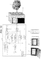
- FIG. 13 is a configuration diagram of a power converter according to a fifth embodiment of the present invention.
- the present embodiment is obtained by applying the fourth embodiment to a drive system of an induction motor.
- reference numerals 1 to 4, 6, 8, 10 to 13', and 14 to 19 of the constituent elements are the same as those in FIGS. 8 and 12 .
- An induction motor 1 that is a component in FIG. 13 is driven by the power conversion apparatus 20.
- reference numerals 4, 6, 8, 10 to 13', and 14 to 19 in FIGS. 8 and 12 are implemented as software, and reference numerals 2 and 2a are implemented as hardware.
- Values of a d-axis current command value I d * and a secondary magnetic flux command value ⁇ 2d * may be made settable by a host device such as a digital operator 20b, a personal computer 21, a tablet 22 and a smartphone 23 of the power conversion apparatus 20.
- the voltage correction values ⁇ V d * and ⁇ V q * has been created from the current command values I d * and I q * and the current detection values I dc and I qc , and a calculation that adds the voltage correction value and the voltage reference value of the vector control, illustrated in (Equation 8), has been performed.
- K pdACR1 represents a proportional gain of the d-axis current control
- K idACR1 represents an integral gain of the d-axis current control
- K pqACR1 represents a proportional gain of the q-axis current control
- K iqACR1 represents an integral gain of the q-axis current control
- V dc * * * R 1 ⁇ I d * * ⁇ ⁇ 1 * L ⁇ ⁇ 1 1 + T d ⁇ s I q * * * *
- V qc * * * R 1 ⁇ I q * * + ⁇ 1 * L ⁇ ⁇ 1 1 + T q ⁇ s I q * * + ⁇ 1 * ⁇ M L 2 ⁇ ⁇ 2 d *
- T d represents a d-axis electric time constant (L d /R)
- T q represents a q- axis electric time constant (L q /R).
- an output frequency command value ⁇ 1 ** illustrated in (Equation 18) and voltage command values V dc ****** and V qc ****** illustrated in (Equation 19) are calculated using the d-axis current command value I d * and a primary delay signal I qctd of the q-axis current detection value I qc , the speed command value ⁇ r *, and electrical constants of the induction motor 1.
- the speed estimation calculation unit 10 has calculated the speed estimated value according to (Equation 9).
- a method of using both the current control and the speed estimation in the q-axis current control may be adopted.
- K pqACR2 represents a proportional gain of current control
- K iqACR2 represents an integral gain of current control
- the speed estimation calculation unit 10 has calculated the speed estimated value according to (Equation 9).
- a speed detection encoder 24 is attached to the induction motor 1, and a speed detection value is calculated from an encoder signal.
- the speed detection encoder 24 is attached to the induction motor 1, and a speed detection calculation unit 10' is provided in place of the speed estimation calculation unit 10 disclosed in the third embodiment. With this configuration, it is possible to accurately detect an actual speed value (speed detection value) ⁇ rd of the induction motor 1.
- FIG. 15 is a configuration diagram of a power conversion apparatus according to a sixth embodiment of the present invention.
- a difference from the third embodiment is that an output frequency ⁇ 1r * instead of a speed command value ⁇ r * is given as a command value from a host device.
- a subtracting unit 25 subtracts a slip frequency command value ⁇ s * from the output frequency command value ⁇ 1r * and outputs the speed command value ⁇ r *.
- a speed detection calculation unit 10' is provided instead of the speed estimation calculation unit 10, whereby a speed detection value ⁇ rd is calculated as an alternative to the speed estimated value ⁇ r ⁇ of the induction motor 1.
- FIG. 16 is a configuration diagram of a power conversion apparatus according to a seventh embodiment of the present invention.
- a difference from the third embodiment is that an output frequency ⁇ 1r * instead of a speed command value ⁇ r * is given as a command value from a host device, the output frequency value ⁇ 1 * is subtracted from the output frequency command value ⁇ 1r * by a subtracting unit 26, and a resultant output frequency value is used as an input signal to the speed control calculation unit.
- a speed detection calculation unit 10' is provided instead of the speed estimation calculation unit 10, whereby a speed detection value ⁇ rd is calculated as an alternative to the speed estimated value ⁇ r ⁇ of the induction motor 1.
- the power conversion apparatus can be used not only for driving of general induction motors, but also for elevator drive motors, in-vehicle drive motors (for construction machinery), motors for hoist cranes, and the like.
Landscapes
- Engineering & Computer Science (AREA)
- Power Engineering (AREA)
- Control Of Ac Motors In General (AREA)
Applications Claiming Priority (2)
| Application Number | Priority Date | Filing Date | Title |
|---|---|---|---|
| JP2015194622A JP6419669B2 (ja) | 2015-09-30 | 2015-09-30 | 電力変換装置およびそのオートチューニング法 |
| PCT/JP2016/071164 WO2017056649A1 (ja) | 2015-09-30 | 2016-07-19 | 電力変換装置およびそのオートチューニング法 |
Publications (3)
| Publication Number | Publication Date |
|---|---|
| EP3358743A1 true EP3358743A1 (de) | 2018-08-08 |
| EP3358743A4 EP3358743A4 (de) | 2019-06-12 |
| EP3358743B1 EP3358743B1 (de) | 2020-10-07 |
Family
ID=58423402
Family Applications (1)
| Application Number | Title | Priority Date | Filing Date |
|---|---|---|---|
| EP16850826.5A Not-in-force EP3358743B1 (de) | 2015-09-30 | 2016-07-19 | Stromumwandlungsvorrichtung und automatisches einstellverfahren dafür |
Country Status (4)
| Country | Link |
|---|---|
| EP (1) | EP3358743B1 (de) |
| JP (1) | JP6419669B2 (de) |
| CN (1) | CN107852124B (de) |
| WO (1) | WO2017056649A1 (de) |
Families Citing this family (6)
| Publication number | Priority date | Publication date | Assignee | Title |
|---|---|---|---|---|
| JP7699908B2 (ja) * | 2018-11-20 | 2025-06-30 | 株式会社日立産機システム | 電力変換装置 |
| WO2020148925A1 (ja) * | 2019-01-16 | 2020-07-23 | 三菱電機株式会社 | 電力変換装置 |
| JP7287885B2 (ja) * | 2019-12-05 | 2023-06-06 | 株式会社日立産機システム | 電力変換装置 |
| JP7286528B2 (ja) * | 2019-12-13 | 2023-06-05 | 株式会社日立産機システム | 電力変換装置 |
| JP7708623B2 (ja) * | 2021-09-14 | 2025-07-15 | 株式会社京三製作所 | 異常検出装置、中央装置及び異常検出方法 |
| JP7217833B1 (ja) * | 2022-11-30 | 2023-02-03 | 日立ジョンソンコントロールズ空調株式会社 | モータ駆動装置、電気定数測定方法および冷凍機器 |
Family Cites Families (11)
| Publication number | Priority date | Publication date | Assignee | Title |
|---|---|---|---|---|
| JPS591072B2 (ja) * | 1979-03-13 | 1984-01-10 | ファナック株式会社 | 正弦波インバ−タ |
| JP3454409B2 (ja) * | 1997-11-14 | 2003-10-06 | 東洋電機製造株式会社 | 誘導電動機の制御装置 |
| KR20040087160A (ko) * | 2003-04-04 | 2004-10-13 | 엘지산전 주식회사 | 유도 전동기의 상호 인덕턴스 추정장치 |
| KR100950410B1 (ko) * | 2003-04-04 | 2010-03-29 | 주식회사 포스코 | 버킷을 이용한 벨트의 고인 물 제거장치 |
| JP3771239B2 (ja) * | 2004-01-19 | 2006-04-26 | 三菱電機株式会社 | 誘導電動機制御装置 |
| JP5418961B2 (ja) * | 2009-04-09 | 2014-02-19 | 富士電機株式会社 | 誘導電動機の制御装置 |
| CN101577427B (zh) * | 2009-05-31 | 2010-12-29 | 国网电力科学研究院武汉南瑞有限责任公司 | 自适应调谐无源电力滤波器的检测控制方法 |
| US8373379B2 (en) * | 2010-10-21 | 2013-02-12 | Schneider Electric USA, Inc. | Methods and devices for estimation of induction motor inductance parameters |
| CN102393507B (zh) * | 2011-09-01 | 2014-01-29 | 北京配天大富精密机械有限公司 | 一种电机参数检测方法及电机参数检测装置 |
| JP2013138548A (ja) * | 2011-12-28 | 2013-07-11 | Kawasaki Heavy Ind Ltd | 誘導電動機の回転速度制御装置および回転速度制御方法 |
| JP5510577B2 (ja) * | 2013-03-11 | 2014-06-04 | 株式会社安川電機 | 誘導電動機のベクトル制御装置 |
-
2015
- 2015-09-30 JP JP2015194622A patent/JP6419669B2/ja active Active
-
2016
- 2016-07-19 CN CN201680046219.2A patent/CN107852124B/zh not_active Expired - Fee Related
- 2016-07-19 EP EP16850826.5A patent/EP3358743B1/de not_active Not-in-force
- 2016-07-19 WO PCT/JP2016/071164 patent/WO2017056649A1/ja not_active Ceased
Also Published As
| Publication number | Publication date |
|---|---|
| JP2017070118A (ja) | 2017-04-06 |
| CN107852124A (zh) | 2018-03-27 |
| CN107852124B (zh) | 2020-06-02 |
| EP3358743B1 (de) | 2020-10-07 |
| JP6419669B2 (ja) | 2018-11-07 |
| WO2017056649A1 (ja) | 2017-04-06 |
| EP3358743A4 (de) | 2019-06-12 |
Similar Documents
| Publication | Publication Date | Title |
|---|---|---|
| EP3358743A1 (de) | Stromumwandlungsvorrichtung und automatisches einstellverfahren dafür | |
| EP2582036B1 (de) | Parameterschätzvorrichtung für ein Antriebssystem eines Permanentmagnetsynchronmotors | |
| US6462492B1 (en) | Position-sensorless controlling method of synchronous motor | |
| CN102751936B (zh) | 电力变换装置、电动机驱动系统 | |
| KR101046802B1 (ko) | 교류 회전기의 제어 장치 및 이 제어 장치를 사용한 교류회전기의 전기적 정수 측정 방법 | |
| US20140197774A1 (en) | Method and apparatus for controlling power converter with inverter output filter | |
| EP1944862B1 (de) | Induktiosmotorsteuerung | |
| US20170264227A1 (en) | Inverter control device and motor drive system | |
| JP6361450B2 (ja) | 誘導電動機の制御装置 | |
| EP3267577A1 (de) | Stromwandlervorrichtung und verfahren zur steuerung davon | |
| US9024552B2 (en) | Current control gain adjusting method for PM motor, current control method, and control device | |
| EP3255784A1 (de) | Motorsteuerungsvorrichtung | |
| KR20160084856A (ko) | 전력변환기의 제어장치 및 전기차 | |
| EP3059851A1 (de) | Antriebsvorrichtung für einen elektromotor | |
| EP3614559B1 (de) | Induktionsmotordrehzahlschätzungsverfahren und leistungsumwandlungsvorrichtung mit verwendung davon | |
| JP2010148198A (ja) | 同期電動機制御装置 | |
| EP3910782A1 (de) | Stromumwandlungsvorrichtung | |
| EP3309953B1 (de) | Energieumwandlungsvorrichtung für induktionsmaschine, sekundärzeitkonstantenmessverfahren und geschwindigkeitsregelungsverfahren | |
| EP4462671A1 (de) | Antriebsvorrichtung für einen induktionsmotor | |
| JP7251424B2 (ja) | インバータ装置及びインバータ装置の制御方法 | |
| EP3214753B1 (de) | Stromumwandlungsvorrichtung und verfahren zur steuerung der stromumwandlungsvorrichtung | |
| EP3683958A1 (de) | Steuervorrichtung und steuerverfahren für einen elektrischen synchronmotor | |
| JP4346574B2 (ja) | サーボモータ制御装置 | |
| JP3849857B2 (ja) | 交流電動機の抵抗測定方法 |
Legal Events
| Date | Code | Title | Description |
|---|---|---|---|
| STAA | Information on the status of an ep patent application or granted ep patent |
Free format text: STATUS: THE INTERNATIONAL PUBLICATION HAS BEEN MADE |
|
| PUAI | Public reference made under article 153(3) epc to a published international application that has entered the european phase |
Free format text: ORIGINAL CODE: 0009012 |
|
| STAA | Information on the status of an ep patent application or granted ep patent |
Free format text: STATUS: REQUEST FOR EXAMINATION WAS MADE |
|
| 17P | Request for examination filed |
Effective date: 20180110 |
|
| AK | Designated contracting states |
Kind code of ref document: A1 Designated state(s): AL AT BE BG CH CY CZ DE DK EE ES FI FR GB GR HR HU IE IS IT LI LT LU LV MC MK MT NL NO PL PT RO RS SE SI SK SM TR |
|
| AX | Request for extension of the european patent |
Extension state: BA ME |
|
| DAV | Request for validation of the european patent (deleted) | ||
| DAX | Request for extension of the european patent (deleted) | ||
| A4 | Supplementary search report drawn up and despatched |
Effective date: 20190514 |
|
| RIC1 | Information provided on ipc code assigned before grant |
Ipc: H02P 27/06 20060101AFI20190508BHEP |
|
| GRAP | Despatch of communication of intention to grant a patent |
Free format text: ORIGINAL CODE: EPIDOSNIGR1 |
|
| STAA | Information on the status of an ep patent application or granted ep patent |
Free format text: STATUS: GRANT OF PATENT IS INTENDED |
|
| RIC1 | Information provided on ipc code assigned before grant |
Ipc: H02P 27/06 20060101AFI20200507BHEP |
|
| INTG | Intention to grant announced |
Effective date: 20200527 |
|
| GRAS | Grant fee paid |
Free format text: ORIGINAL CODE: EPIDOSNIGR3 |
|
| GRAA | (expected) grant |
Free format text: ORIGINAL CODE: 0009210 |
|
| STAA | Information on the status of an ep patent application or granted ep patent |
Free format text: STATUS: THE PATENT HAS BEEN GRANTED |
|
| AK | Designated contracting states |
Kind code of ref document: B1 Designated state(s): AL AT BE BG CH CY CZ DE DK EE ES FI FR GB GR HR HU IE IS IT LI LT LU LV MC MK MT NL NO PL PT RO RS SE SI SK SM TR |
|
| REG | Reference to a national code |
Ref country code: GB Ref legal event code: FG4D |
|
| REG | Reference to a national code |
Ref country code: CH Ref legal event code: EP Ref country code: AT Ref legal event code: REF Ref document number: 1322240 Country of ref document: AT Kind code of ref document: T Effective date: 20201015 |
|
| REG | Reference to a national code |
Ref country code: IE Ref legal event code: FG4D |
|
| REG | Reference to a national code |
Ref country code: DE Ref legal event code: R096 Ref document number: 602016045568 Country of ref document: DE |
|
| REG | Reference to a national code |
Ref country code: NL Ref legal event code: MP Effective date: 20201007 |
|
| REG | Reference to a national code |
Ref country code: AT Ref legal event code: MK05 Ref document number: 1322240 Country of ref document: AT Kind code of ref document: T Effective date: 20201007 |
|
| PG25 | Lapsed in a contracting state [announced via postgrant information from national office to epo] |
Ref country code: FI Free format text: LAPSE BECAUSE OF FAILURE TO SUBMIT A TRANSLATION OF THE DESCRIPTION OR TO PAY THE FEE WITHIN THE PRESCRIBED TIME-LIMIT Effective date: 20201007 Ref country code: GR Free format text: LAPSE BECAUSE OF FAILURE TO SUBMIT A TRANSLATION OF THE DESCRIPTION OR TO PAY THE FEE WITHIN THE PRESCRIBED TIME-LIMIT Effective date: 20210108 Ref country code: NO Free format text: LAPSE BECAUSE OF FAILURE TO SUBMIT A TRANSLATION OF THE DESCRIPTION OR TO PAY THE FEE WITHIN THE PRESCRIBED TIME-LIMIT Effective date: 20210107 Ref country code: PT Free format text: LAPSE BECAUSE OF FAILURE TO SUBMIT A TRANSLATION OF THE DESCRIPTION OR TO PAY THE FEE WITHIN THE PRESCRIBED TIME-LIMIT Effective date: 20210208 Ref country code: RS Free format text: LAPSE BECAUSE OF FAILURE TO SUBMIT A TRANSLATION OF THE DESCRIPTION OR TO PAY THE FEE WITHIN THE PRESCRIBED TIME-LIMIT Effective date: 20201007 |
|
| REG | Reference to a national code |
Ref country code: LT Ref legal event code: MG4D |
|
| PG25 | Lapsed in a contracting state [announced via postgrant information from national office to epo] |
Ref country code: SE Free format text: LAPSE BECAUSE OF FAILURE TO SUBMIT A TRANSLATION OF THE DESCRIPTION OR TO PAY THE FEE WITHIN THE PRESCRIBED TIME-LIMIT Effective date: 20201007 Ref country code: AT Free format text: LAPSE BECAUSE OF FAILURE TO SUBMIT A TRANSLATION OF THE DESCRIPTION OR TO PAY THE FEE WITHIN THE PRESCRIBED TIME-LIMIT Effective date: 20201007 Ref country code: ES Free format text: LAPSE BECAUSE OF FAILURE TO SUBMIT A TRANSLATION OF THE DESCRIPTION OR TO PAY THE FEE WITHIN THE PRESCRIBED TIME-LIMIT Effective date: 20201007 Ref country code: BG Free format text: LAPSE BECAUSE OF FAILURE TO SUBMIT A TRANSLATION OF THE DESCRIPTION OR TO PAY THE FEE WITHIN THE PRESCRIBED TIME-LIMIT Effective date: 20210107 Ref country code: PL Free format text: LAPSE BECAUSE OF FAILURE TO SUBMIT A TRANSLATION OF THE DESCRIPTION OR TO PAY THE FEE WITHIN THE PRESCRIBED TIME-LIMIT Effective date: 20201007 Ref country code: IS Free format text: LAPSE BECAUSE OF FAILURE TO SUBMIT A TRANSLATION OF THE DESCRIPTION OR TO PAY THE FEE WITHIN THE PRESCRIBED TIME-LIMIT Effective date: 20210207 Ref country code: LV Free format text: LAPSE BECAUSE OF FAILURE TO SUBMIT A TRANSLATION OF THE DESCRIPTION OR TO PAY THE FEE WITHIN THE PRESCRIBED TIME-LIMIT Effective date: 20201007 |
|
| PG25 | Lapsed in a contracting state [announced via postgrant information from national office to epo] |
Ref country code: NL Free format text: LAPSE BECAUSE OF FAILURE TO SUBMIT A TRANSLATION OF THE DESCRIPTION OR TO PAY THE FEE WITHIN THE PRESCRIBED TIME-LIMIT Effective date: 20201007 Ref country code: HR Free format text: LAPSE BECAUSE OF FAILURE TO SUBMIT A TRANSLATION OF THE DESCRIPTION OR TO PAY THE FEE WITHIN THE PRESCRIBED TIME-LIMIT Effective date: 20201007 |
|
| REG | Reference to a national code |
Ref country code: DE Ref legal event code: R097 Ref document number: 602016045568 Country of ref document: DE |
|
| PG25 | Lapsed in a contracting state [announced via postgrant information from national office to epo] |
Ref country code: RO Free format text: LAPSE BECAUSE OF FAILURE TO SUBMIT A TRANSLATION OF THE DESCRIPTION OR TO PAY THE FEE WITHIN THE PRESCRIBED TIME-LIMIT Effective date: 20201007 Ref country code: SK Free format text: LAPSE BECAUSE OF FAILURE TO SUBMIT A TRANSLATION OF THE DESCRIPTION OR TO PAY THE FEE WITHIN THE PRESCRIBED TIME-LIMIT Effective date: 20201007 Ref country code: LT Free format text: LAPSE BECAUSE OF FAILURE TO SUBMIT A TRANSLATION OF THE DESCRIPTION OR TO PAY THE FEE WITHIN THE PRESCRIBED TIME-LIMIT Effective date: 20201007 Ref country code: SM Free format text: LAPSE BECAUSE OF FAILURE TO SUBMIT A TRANSLATION OF THE DESCRIPTION OR TO PAY THE FEE WITHIN THE PRESCRIBED TIME-LIMIT Effective date: 20201007 Ref country code: CZ Free format text: LAPSE BECAUSE OF FAILURE TO SUBMIT A TRANSLATION OF THE DESCRIPTION OR TO PAY THE FEE WITHIN THE PRESCRIBED TIME-LIMIT Effective date: 20201007 Ref country code: EE Free format text: LAPSE BECAUSE OF FAILURE TO SUBMIT A TRANSLATION OF THE DESCRIPTION OR TO PAY THE FEE WITHIN THE PRESCRIBED TIME-LIMIT Effective date: 20201007 |
|
| PGFP | Annual fee paid to national office [announced via postgrant information from national office to epo] |
Ref country code: FR Payment date: 20210628 Year of fee payment: 6 |
|
| PLBE | No opposition filed within time limit |
Free format text: ORIGINAL CODE: 0009261 |
|
| STAA | Information on the status of an ep patent application or granted ep patent |
Free format text: STATUS: NO OPPOSITION FILED WITHIN TIME LIMIT |
|
| PG25 | Lapsed in a contracting state [announced via postgrant information from national office to epo] |
Ref country code: DK Free format text: LAPSE BECAUSE OF FAILURE TO SUBMIT A TRANSLATION OF THE DESCRIPTION OR TO PAY THE FEE WITHIN THE PRESCRIBED TIME-LIMIT Effective date: 20201007 |
|
| 26N | No opposition filed |
Effective date: 20210708 |
|
| PG25 | Lapsed in a contracting state [announced via postgrant information from national office to epo] |
Ref country code: AL Free format text: LAPSE BECAUSE OF FAILURE TO SUBMIT A TRANSLATION OF THE DESCRIPTION OR TO PAY THE FEE WITHIN THE PRESCRIBED TIME-LIMIT Effective date: 20201007 |
|
| PGFP | Annual fee paid to national office [announced via postgrant information from national office to epo] |
Ref country code: IT Payment date: 20210728 Year of fee payment: 6 |
|
| PG25 | Lapsed in a contracting state [announced via postgrant information from national office to epo] |
Ref country code: SI Free format text: LAPSE BECAUSE OF FAILURE TO SUBMIT A TRANSLATION OF THE DESCRIPTION OR TO PAY THE FEE WITHIN THE PRESCRIBED TIME-LIMIT Effective date: 20201007 |
|
| PGFP | Annual fee paid to national office [announced via postgrant information from national office to epo] |
Ref country code: DE Payment date: 20210723 Year of fee payment: 6 |
|
| REG | Reference to a national code |
Ref country code: CH Ref legal event code: PL |
|
| GBPC | Gb: european patent ceased through non-payment of renewal fee |
Effective date: 20210719 |
|
| PG25 | Lapsed in a contracting state [announced via postgrant information from national office to epo] |
Ref country code: MC Free format text: LAPSE BECAUSE OF FAILURE TO SUBMIT A TRANSLATION OF THE DESCRIPTION OR TO PAY THE FEE WITHIN THE PRESCRIBED TIME-LIMIT Effective date: 20201007 |
|
| REG | Reference to a national code |
Ref country code: BE Ref legal event code: MM Effective date: 20210731 |
|
| PG25 | Lapsed in a contracting state [announced via postgrant information from national office to epo] |
Ref country code: LI Free format text: LAPSE BECAUSE OF NON-PAYMENT OF DUE FEES Effective date: 20210731 Ref country code: GB Free format text: LAPSE BECAUSE OF NON-PAYMENT OF DUE FEES Effective date: 20210719 Ref country code: CH Free format text: LAPSE BECAUSE OF NON-PAYMENT OF DUE FEES Effective date: 20210731 |
|
| PG25 | Lapsed in a contracting state [announced via postgrant information from national office to epo] |
Ref country code: IS Free format text: LAPSE BECAUSE OF FAILURE TO SUBMIT A TRANSLATION OF THE DESCRIPTION OR TO PAY THE FEE WITHIN THE PRESCRIBED TIME-LIMIT Effective date: 20210207 Ref country code: LU Free format text: LAPSE BECAUSE OF NON-PAYMENT OF DUE FEES Effective date: 20210719 |
|
| PG25 | Lapsed in a contracting state [announced via postgrant information from national office to epo] |
Ref country code: IE Free format text: LAPSE BECAUSE OF NON-PAYMENT OF DUE FEES Effective date: 20210719 Ref country code: BE Free format text: LAPSE BECAUSE OF NON-PAYMENT OF DUE FEES Effective date: 20210731 |
|
| REG | Reference to a national code |
Ref country code: DE Ref legal event code: R119 Ref document number: 602016045568 Country of ref document: DE |
|
| PG25 | Lapsed in a contracting state [announced via postgrant information from national office to epo] |
Ref country code: FR Free format text: LAPSE BECAUSE OF NON-PAYMENT OF DUE FEES Effective date: 20220731 |
|
| PG25 | Lapsed in a contracting state [announced via postgrant information from national office to epo] |
Ref country code: DE Free format text: LAPSE BECAUSE OF NON-PAYMENT OF DUE FEES Effective date: 20230201 |
|
| PG25 | Lapsed in a contracting state [announced via postgrant information from national office to epo] |
Ref country code: CY Free format text: LAPSE BECAUSE OF FAILURE TO SUBMIT A TRANSLATION OF THE DESCRIPTION OR TO PAY THE FEE WITHIN THE PRESCRIBED TIME-LIMIT Effective date: 20201007 |
|
| PG25 | Lapsed in a contracting state [announced via postgrant information from national office to epo] |
Ref country code: IT Free format text: LAPSE BECAUSE OF NON-PAYMENT OF DUE FEES Effective date: 20220719 Ref country code: HU Free format text: LAPSE BECAUSE OF FAILURE TO SUBMIT A TRANSLATION OF THE DESCRIPTION OR TO PAY THE FEE WITHIN THE PRESCRIBED TIME-LIMIT; INVALID AB INITIO Effective date: 20160719 |
|
| PG25 | Lapsed in a contracting state [announced via postgrant information from national office to epo] |
Ref country code: MK Free format text: LAPSE BECAUSE OF FAILURE TO SUBMIT A TRANSLATION OF THE DESCRIPTION OR TO PAY THE FEE WITHIN THE PRESCRIBED TIME-LIMIT Effective date: 20201007 |
|
| PG25 | Lapsed in a contracting state [announced via postgrant information from national office to epo] |
Ref country code: MT Free format text: LAPSE BECAUSE OF FAILURE TO SUBMIT A TRANSLATION OF THE DESCRIPTION OR TO PAY THE FEE WITHIN THE PRESCRIBED TIME-LIMIT Effective date: 20201007 |
|
| PG25 | Lapsed in a contracting state [announced via postgrant information from national office to epo] |
Ref country code: TR Free format text: LAPSE BECAUSE OF FAILURE TO SUBMIT A TRANSLATION OF THE DESCRIPTION OR TO PAY THE FEE WITHIN THE PRESCRIBED TIME-LIMIT Effective date: 20201007 |