EP3358791A1 - Verfahren zum senden von nachrichten von einem emittierenden verbundenen gegenstand an mindestens einen empfangenden verbundenen gegenstand durch mindestens ein netzelement - Google Patents
Verfahren zum senden von nachrichten von einem emittierenden verbundenen gegenstand an mindestens einen empfangenden verbundenen gegenstand durch mindestens ein netzelement Download PDFInfo
- Publication number
- EP3358791A1 EP3358791A1 EP17154316.8A EP17154316A EP3358791A1 EP 3358791 A1 EP3358791 A1 EP 3358791A1 EP 17154316 A EP17154316 A EP 17154316A EP 3358791 A1 EP3358791 A1 EP 3358791A1
- Authority
- EP
- European Patent Office
- Prior art keywords
- network element
- data
- plane
- message
- port
- Prior art date
- Legal status (The legal status is an assumption and is not a legal conclusion. Google has not performed a legal analysis and makes no representation as to the accuracy of the status listed.)
- Withdrawn
Links
- 238000000034 method Methods 0.000 title claims abstract description 80
- 238000004590 computer program Methods 0.000 claims description 6
- 238000010200 validation analysis Methods 0.000 claims description 3
- 230000006870 function Effects 0.000 description 13
- 230000005540 biological transmission Effects 0.000 description 5
- 238000001914 filtration Methods 0.000 description 5
- 238000002955 isolation Methods 0.000 description 5
- 238000010586 diagram Methods 0.000 description 3
- 230000009471 action Effects 0.000 description 2
- 238000013459 approach Methods 0.000 description 2
- 238000005538 encapsulation Methods 0.000 description 2
- 230000006855 networking Effects 0.000 description 2
- 230000008569 process Effects 0.000 description 2
- 230000000903 blocking effect Effects 0.000 description 1
- 230000008034 disappearance Effects 0.000 description 1
- 230000003993 interaction Effects 0.000 description 1
- 238000013507 mapping Methods 0.000 description 1
- 238000005457 optimization Methods 0.000 description 1
- 238000012545 processing Methods 0.000 description 1
- 238000012546 transfer Methods 0.000 description 1
- 230000005641 tunneling Effects 0.000 description 1
- 239000002699 waste material Substances 0.000 description 1
Images

Classifications
-
- H—ELECTRICITY
- H04—ELECTRIC COMMUNICATION TECHNIQUE
- H04L—TRANSMISSION OF DIGITAL INFORMATION, e.g. TELEGRAPHIC COMMUNICATION
- H04L12/00—Data switching networks
- H04L12/28—Data switching networks characterised by path configuration, e.g. LAN [Local Area Networks] or WAN [Wide Area Networks]
- H04L12/46—Interconnection of networks
-
- H—ELECTRICITY
- H04—ELECTRIC COMMUNICATION TECHNIQUE
- H04L—TRANSMISSION OF DIGITAL INFORMATION, e.g. TELEGRAPHIC COMMUNICATION
- H04L45/00—Routing or path finding of packets in data switching networks
- H04L45/16—Multipoint routing
-
- H—ELECTRICITY
- H04—ELECTRIC COMMUNICATION TECHNIQUE
- H04L—TRANSMISSION OF DIGITAL INFORMATION, e.g. TELEGRAPHIC COMMUNICATION
- H04L45/00—Routing or path finding of packets in data switching networks
- H04L45/38—Flow based routing
-
- H—ELECTRICITY
- H04—ELECTRIC COMMUNICATION TECHNIQUE
- H04L—TRANSMISSION OF DIGITAL INFORMATION, e.g. TELEGRAPHIC COMMUNICATION
- H04L45/00—Routing or path finding of packets in data switching networks
- H04L45/64—Routing or path finding of packets in data switching networks using an overlay routing layer
Definitions
- the present invention relates a method for transmitting messages from an emitting connected object to at least one receiving connected object through at least one network element, as well as a computer program comprising means for performing this method, a network element comprising means for implementing this method, and a controlling device for configuring this network element.
- VLAN allows specifying Virtual Local Area Networks.
- connected objects physically connected (wired or wireless) to each other through one or more switches can communicate with each other within a Local Area Network (LAN) only if they belong to the same VLAN.
- LAN Local Area Network
- a layer-2-broadcast message from a connected object is broadcasted only to connected objects belonging to the same the VLAN.
- VLAN and other traffic isolation techniques such as GRE (Generic Routing Encapsulation), VXLAN (Virtual extensible Local Area Network) and MPLS (Multi Protocol Label Switching) label, involve several issues.
- GRE Generic Routing Encapsulation
- VXLAN Virtual extensible Local Area Network
- MPLS Multi Protocol Label Switching
- a typical simple object has only one WiFi LAN connection (i.e. one network connection).
- a connected object belonging to a plurality of VLANs sends a multicast/broadcast packet, it has to duplicate this packet and send it out over multiple VLANs.
- the application running on the connected object is aware of VLANs and capable of multicasting/broadcasting on multiple VLANs simultaneously. This is not the case of the majority of devices and related applications, even powerful ones such as a PC (Personal Computer) or a smart phone.
- a connected object which has several VLANs in common with the emitting connected object receives the same multicast/broadcast information more than once.
- the application on the receiving connected object should be able to compare information received on the VLANs in order to discard redundant information. Without doing such discard, the application/protocol state machine could be corrupted by such information duplication, as it is, in general, not designed to work to receive the same information on different network interfaces.
- embodiments relate to a method for transmitting messages from an emitting connected object to at least one receiving connected object through at least one network element, said network element comprising at least two ports connected respectively to said emitting connected object and to said receiving connected object, either directly or through one or more other network elements, said method providing for configuring the network element according to a procedure which provides for:
- embodiments relate to a computer program comprising instructions for performing such a method when said instructions are executed by a computer.
- embodiments relate to a controlling device for configuring a network element intended to transmit messages from an emitting connected object to at least one receiving connected object, said network element comprising at least two ports connected respectively to said emitting connected object and to said receiving connected object, either directly or through one or more other network elements, said controlling device comprising means for:
- embodiments relate to a network element for transmitting messages from an emitting connected object to at least one receiving connected object through at least one network element, said network element comprising at least two ports connected respectively to said emitting connected object and to said receiving connected object, either directly or through one or more other network elements, said network element comprising means for executing a configuration procedure, said means comprising means for:
- the network elements are located at a plurality of sites interconnected by remote links forming a fully meshed topology, the method comprising: determining a logical topology wherein a packet entering the network element by one remote link cannot be forwarded to another remote link.
- At least some of the network elements are connected by local links, the method comprising: determining a loop free topology of local links.
- Configuring said network element may comprise sending forwarding and/or filtering rules by using the Open Flow protocol.
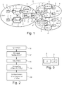
- Figure 1 is a block diagram of a network 1 comprising a plurality of network elements 2, a plurality of connected objects 3 and a plurality of controlling devices 4 arranged at one or more sites 5.
- a network element 2 is a packet forwarding device responsible for receiving packets and forwarding the received packets according to forwarding rules, based in particular on a source address and a destination address included in each packet but also on other packet header fields and potentially on the analyze of the payload content.
- a network element 2 is a switch and the forwarding rules may be configured by using the Open Flow protocol.
- a network element 2 comprises several network interfaces. Eventually, we could divide each of those network interfaces further into several logical network interfaces - e.g. in the case when a physical device is declined in several logical devices with each of the logical devices connected to a logical network interface. For simplicity, each of the aforementioned network interfaces (logical or not) will be called as a port P.
- IoT-ports P those which are directly (physically or logically) connected to a connected object 3, hereafter called IoT-ports P"
- Non-IoT-ports P' those which are not directly connected to a connected object 3
- local ports and remote ports connect the network element 2 to another local network element 2 within the same site 5, directly or indirectly via unmanaged network element (an unmanaged network is a network element which cannot be configured accordingly to the method described in this document), while remote ports connect the network element 2 to another remote network element 2 in a remote site 5.
- the networks elements 2 are denoted NE1, NE11, NE12, NE2 and NE3, and the ports are denoted P1.1, P1.2, P1.3, P1.4, P11.1, P11.2, P12.1, P12.2, P2.1, P2.2, P2.3, P2.4, P3.1, P3.2, P3.3 and P3.4.
- At least two ports P k of said network element are necessarily connected respectively to said emitting connected object and to said receiving connected object, either directly (through an IoT-port P") or through one or more other network elements 2 (through a non-IoT-port P').
- connected object designate, in this document, either a physical device or a logical device (a subset - e.g. a particular application - of the associated physical connected device) depending on the context (e.g. connected to a physical or a logical network interface).
- a connected object 3 may be one logical declination of any type of devices bound with one or several (may be all) communicating applications running on it, capable of sending and/or receiving messages (for example packets or frames) on the network 1.
- the connected objects 3 are denoted d 1.1 , d 1.2 , d 2.1 , d 2.2 , d 3.1 and d 3.2 .
- d 2.1 and d 2.2 could be the same physical device sharing a common network interface but each of them considered (by the controlling device 4) as two different entities emitting different types of traffic according to the related applications that have to be handled and forwarded differently.
- a controlling device 4 is responsible for configuring one or more network elements 2.
- a controlling device 4 is associated with each site 5 and is responsible for configuring the network elements 2 of the associated site 5. Controlling devices 4 may exchange information between them. Eventually a given controlling device 4 can have access to all the control information across the network 1 - there could be considered here as a "centralized" control architecture. Thus, in some embodiments, a single controlling device 4 may be responsible for configuring network elements 2 of various sites 5.
- the controlling devices 4 are denoted Controller-1, Controller-2 and Controller-3, respectively.
- a local link may include for example a wireless and/or a wired connection, eventually with intermediate unmanaged network elements.
- the controlling device 4 configures the network elements 2 such that the local links 6 form a loop free topology, for example by using the spanning tree algorithm. This is illustrated on figure 1 by the deactivated local link 6' connecting two network interfaces (not shown) of network elements NE11 and NE12. Such network interfaces are not used in the network 1 and are not ports within the meaning of this description.
- the remote links 7 may be realized by tunneling technique, such as GRE (Generic Routing Encapsulation), VXLAN (Virtual extensible Local Area Network), or VLL (Virtual Leased Line), over an IP (Internet Protocol) wide area network, for example.
- GRE Generic Routing Encapsulation
- VXLAN Virtual extensible Local Area Network
- VLL Virtual Leased Line
- IP Internet Protocol
- controlling devices 4 determine also a loop-free logical topology, for example by applying a split-horizon technique.
- the controlling devices 4 from each site 5 discuss with its peers via a semaphore network 8 (see dashed arrows in Figure 1 ).
- the latter could be either implemented as in-band (i.e. taking the same path as data traffics) or as out-of-band (i.e. a dedicated infrastructure).
- the controlling device 4 of each site can have access to information from remote sites via the semaphore network 8.
- the described architecture could be seen as a "centralized" architecture at the control level (i.e. information from remote sites could be "centralized” by a local controlling device 4).
- the network 1 uses a traffic isolation technique wherein sets of connected objects 3 allowed to communicate with each other are specified.
- a set of connected objects 3 allowed to communicate with each other is called herein a SD-LAN, for Software-Defined Local Area Network.
- “Local” here does not mean within a single site 5, but rather that packets are forwarded in this example based on Layer 2 information without the need of Layer 3 routing.
- a SD-LAN may be defined by a semi-automatic process, based on service requests from users through a simple user interface. For example, a user of a Smartphone may request a video playing service, and this will result in the creation of a SD-LAN including the Smartphone, a video server and a TV. For another example, a user would like to restraint DHCP request messages issue from all client devices to only DHCP servers. In this last example the broadcast messages issue from a DHCP client (alternatively a server) are only forwarded to DHCP servers (alternatively the concerned client). This could be done using UDP (User Datagram Protocol) ports 67 and 68 to distinguish DHCP broadcast traffic from other broadcast traffic of other applications.
- UDP User Datagram Protocol
- the method provides for configuring the network elements 2 in function of the specified SD-LANs, according to the configuration procedure described herein below.
- the configuration procedure For configuring a given network element 2, the configuration procedure first provides for transmitting, from a controlling device 4 associated with said network element to said network element, data-plane tagging information specifying at least one set of connected objects 3 allowed to communicate with each other through said network element.
- the data-plane tagging information may be generated by the controlling device 4 from control tagging information which are stored by said controlling device.
- Figure 2 is a flowchart of steps executed by a controlling device 4 during a procedure which allows for configuring one or more network element 2. The following notations are used in the description:
- the controlling device 4 associated with one network element 2 may identify the connected objects 3 connected to the network element 2 and the associated Inports P (Step S1). For example, as the connected objects 3 send messages in the network 1, a given controlling device 4 learns/discovers the existence of a new connected object i thanks to these messages containing identification information (id i ) allowing to identify this new connected object i entering the associated network element 2.
- the method can provide, upon reception by a port Pk of the network element 2 of a first message from a new connected object i, that said network element further sends a request to the controlling device 4 for such an identification.
- the controlling device 4 registers then connected object i as a known connected object and memorizes the port P (which is a non-IoT-port P' or an IoT-port P") where this identification information has entered the network element 2, i.e. the port P, P', P" which have received the first message from the new connected object i. Within each network element 2, this latter port is called the Inport(d i ). It is noted that there is one unique Inport(d i ) per network element 2 associated to a given connected object i, otherwise there is a potential loop.
- connected objects 3 may be identified only according to their MAC (Media Access Control) addresses and others may be identified when emitting IP (Internet Protocol) packet on TCP (Transmission Control Protocol) port 8095 (that may be used to identify a specific application).
- IP Internet Protocol
- TCP Transmission Control Protocol
- the reader can replace identification information by any identification filter to apply on received messages in order to identify uniquely different connected objects 3 relatively to other connected objects 3 even if the distinction between connected objects 3 may be realized through filtering hierarchy definition.
- the controlling device 4 may obtain logical topology information specifying at least one SD-LAN in the network 1.
- the logical topology information LT include a list of SD-LANs S k , S l , S m and, for each SD-LAN, the list of d i belonging to the SD-LAN. This is equivalent to the logical topology information LT including, for each d i , the list of SD-LAN to which it belongs.
- the logical topology information LT allows for determining T(V(d i )).
- the controlling device 4 may tag the ports P, P', P" of the associated network elements 2, in function of the logical topology information LT (Step S3). More specifically, for a port P k , the controlling device 4 may associate control-plane tags T(P k ) specifying the SD-LANs accessible through the port P k , these control-plane tags T(Pk) further being used as control tagging information for generating data-plane tagging information, as it will be described further below.
- the controlling device 4 tags only the IoT-ports P". In another embodiment, the controlling device 4 tags the IoT-ports P" and the Non-IoT-ports P'. In both cases, this can be done in function of the logical topology information LT by tagging the Inport(d i ) of connected object d i : T(P k ) ⁇ T(V(d i )), where V(d i ) is specified by the logical topology information LT.
- the network element 2 may flood the packet to other ports to allow other network elements 2 to learn about the connected object i and tag the corresponding Inport(d i ). This can be done for example as described hereafter in pseudo-code:
- Tagging non-IoT-ports P' is well-adapted to flat networks while it might rather be complex to tag non-IoT-port P' in hierarchical networks with a high number of hierarchical levels and highly dynamic appearance/disappearance of connected objects 3 (i.e. connected objects 3 entering and exiting the network 1 at high rate, a significant number of non-IoT-port tags may need to be refreshed).
- the controlling device 4 may determine, for each identified connected object 3, d i , a multicast tree mTree from the associated Inport(d i ) to one or more other ports P k of the network element 2, in function of the logical topology data LT and the control-plan tags T(P k ) determined at step S3 (Step S4).
- a multicast tree mTree from the associated Inport(d i ) to one or more other ports P k of the network element 2
- the control-plan tags T(P k ) determined at step S3 Step S4
- one of the following algorithm described in pseudo-code may be applied for each network element 2.
- the controlling device 4 may configure the network elements 2 for forwarding SD-LANs multicast and/or broadcast messages received from a connected object d i according to the determined multicast tree mTree (Step S5).
- the controlling device 4 sends multicast/broadcast forwarding rules and/or filtering rules to the network element 2, for example by using the Open Flow protocol.
- the controlling device 4 outputs configuration data to a human operator, which may then use the configuration data to manually configure the network elements 2.
- some of SD-LANs multicast and/or broadcast may be specific. For example a SD-LAN can stipulate that its broadcast concerned only TCP port 8095.
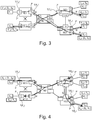
- FIG 3 shows the results of the method of Figure 2 applied to the network 1.
- three SD-LANs have been specified and the controlling devices 4 tags both IoT-ports and Non-IoT-ports.
- the specified SD-LANs are S r , comprising d 1.1 , d 2.2 and d 3.2 , Sg, comprising d 2.1 and d 3.2 , and S b , comprising d 1.1 , d 1.2 and d 3.1 .
- the controlling devices 4 have tagged the ports under their respective responsibility. More specifically, Controller-1 tags all ports of NE1, NE11 and NE12, Controller-2 all ports of NE2 and Controller-3 all ports of NE3. For each IoT-port, the controlling device 4 tags them with the SD-LAN IDs the associated connected object pertains to. For instance, Controller-1 tags the IoT-port, P11.1, with two tags, r and b, as the associated connected object, d1.1, pertains to two SD-LANs S r and S b . For each non-IoT port, the controlling device 4 tags it with IDs of all SD-LANs (local and remote) reachable when a packet exits the network element 2 by this port.
- Controller-1 tags the non-IoT port, P11.2, with all the SD-LAN IDs, meaning r, b and g, as one can reach all 3 SD-LANs when exiting the NE11 by this port.
- Controller-1 tags the non-IoT port, P1.1, with only two tags, r, b, as one can only reach connected objects pertaining to these two SD-LANs (i.e. only connected objects d11.1 in the present network 1), S r and S b , when exiting the NE1 via this port.
- Controller-2 only tags port P2.3 with only two tags, meaning r and b, as Sg should not be reachable via this port as per the "split horizon" procedure applied at the NE1 level by Controller-1 (i.e. traffic received at a remote port cannot be forwarded to another remote port).
- each controlling device 4 can build up a multicast/broadcast tree depending on the originating connected object following the procedure described with reference to Figure 2 .
- Figure 3 illustrates the end-to-end multicast tree from connected object d 1.1 .
- This multicast tree is the concatenation of multicast trees mTree produced for each network element 2 for the same multicast traffic.
- Figure 4 shows the results of the method of Figure 2 applied to the network 1.
- three SD-LANs have been specified and the controlling devices 4 tag only IoT-ports.
- the specified SD-LANs are the same as in Figure 3 , namely S r , comprising d 1.1 , d 2.2 and d 3.2 , Sg, comprising d 2.1 and d 3.2 , and S b , comprising d 1.1 , d 1.2 and d 3.1 .
- Figure 4 shows the multicast tree originating from connected object d2.2, which is the concatenation of the multicast trees mTree determined for each network element 2.
- the second algorithm generates more multicast traffics than the first algorithm. This is a tradeoff which aims at fewer network states.
- CPU Central Processing Unit
- connecting objects 3 can work as if they were in a traditional LAN network, but with a better control of their traffics.
- the configuration procedure For allowing the transmission of messages M, which can be broadcast/multicast messages or unicast messages, through a network element 2, the configuration procedure provides, as mentioned hereinabove, to use control tagging information stored by a controlling device associated 4 with said network element 2, especially based on control-plane tags T(P k ) associated with ports P k of said network element, for generating data-plane tagging information to be transmitted to said network element.
- the configuration procedure can notably provide that the controlling device 4 generates such data-plane tagging information by translating such control tagging information in a format readable by said network element.
- the configuration procedure provides, for at least one port P k of the network element 2, for associating said port with one or more data-plane tags DPT(P k ) respectively identifying a set of connected objects including one or more connected objects 3 accessible through said port, in function of the data-plane tagging information.
- the method can provide for transmitting data-plane tagging information upon reception by a port P k of the network element 2 of a first message from a new connected object 3, said network element further sending, through dedicated means, a request to the controlling device 4 for obtaining said data-plane tagging information, and then associating the receiving port P k with a data-plane tag DPT(P k ) according to said data-plane tagging information.
- the sending of this request can be performed during the identification step S1, the generation and transmission of data-plane tagging information being performed in parallel to the control-plane tag association step S3.
- the controlling device 4 comprises means that are arranged for generating and transmitting to the network element 2 such data-plane tagging information, and more particularly means that are arranged for translating such control tagging information in a format readable by said network element.
- the network element 2 comprises means for receiving such data-plane tagging information, as well as means for associating the one or more data-plane tags DPT(P k ) to the corresponding port P k by means of said translated control tagging information.
- FIG. 6 is a flowchart of an embodiment of this data-plane tag association step.
- the network element 2 can notably implement at each of its ports P k the one or more associated data-plane tag DPT(P k ) as metadata words.
- the network element 2 can store tags DPT(P k ) in two 64-Bits B metadata words 9a, 9b, and the controlling device 4 can store a mapping between the respective global identifiers Cl 1 , Cl 2 , Cl 3 , Cl 4 of each SD-LAN and the bit position B 1 , B 2 , B 3 , B 4 within the local metadata words 9a, 9b.
- the controlling device 4 may observe a limited number of SD-LANs, notably less than 128 SD-LANs.
- the controlling device 4 can dedicate a bit B 1 , B 2 , B 3 , B 4 of the metadata words 9a, 9b of an output port P k to each of the observed SD-LANs.
- the value of a dedicated bit B, B 1 , B 2 , B 3 , B 4 is set to 1 - respectively 0 - to indicate that the output port P k is tagged - respectively not tagged - with the associated SD-LAN.
- the method provides, upon the reception by a network element 2 of a message M from an emitting connected object 3 to be transmitted to at least one receiving connected object 3, for executing by dedicated means of said network element a procedure for forwarding said message to said receiving connected object.
- This forwarding procedure provides a first step for associating the message M with one data-plane tag DPT(M) which is created according to a data plane rule generated by the controlling device 4 and to at least one information about the emitting connecting object 3 provided within said message.
- the controlling device 4 comprises means for generating such a data plane rule
- the network element 2 comprises means for creating and associating such a data-plane tag DPT(M) to the message M.
- the data-plane tag DPT(M) is created according to information about the at least one set of connected objects 3 (SD-LAN) to which the emitting connected object 3 pertains. Moreover, the data-plane tag DPT(M) can be created with a 2 k -Bit format, with k being an integer number, for example with a 128-Bit format, especially if the number of sets SD-LAN of connected objects 3 observed by the network element 2 is less or equal to 128.
- the data-plane tag DPT(M) can also be created according to an eventual consecutive network element of the present network element 2 on the data path between the emitted connected object 3 and the at least one receiving connected object 3.
- the network element 2 can identify the emitting connected object 3 by means of a source Media Access Control (MAC) address, or any other type of similar information, that can be inserted within the header Ma or the payload Mb of the message M.
- MAC Media Access Control
- Figure 7 shows a first example of a data-plane tag DPT(M) according to a first variant, wherein the data plane rule generated by the controlling device 4 allows the network element 2 for creating said data-plane tag by using internal metadata words 10a, 10b associated with the message M.
- the network element 2 can create a 128-Bit metadata word, either from two 64-Bit metadata words 11 a, 11 b, as represented on the figure, or from four 32-Bit metadata words.
- the data plane rule allows the network element 2 for producing a data-plane tag DPT(M) upon modifying the internal metadata words 10a, 10b associated to the message M with respective marks/values 12a, 12b depending on the at least one set of SD-LANs to which the emitting object 3 pertains.
- the network element 2 can notably use data-plane tagging information such as those used during the data-plane tag port associating step, which provides for associating dedicated local bits to respectively one global identifier of a set SD-LAN.
- Figure 8 shows a second example of a data-plane tag DPT(M) according to a second variant, wherein the data plane rule generated by the controlling device 4 allows the network element 2 for creating said tag by using Multi-Protocol Label Switching (MPLS) labels, said data-plane tag being then inserted within the header Ma of the message M.
- MPLS Multi-Protocol Label Switching
- the data plane rule can provide for creating a 128-Bit tag from four 32-Bit MPLS labels.
- the forwarding procedure then provides a step for determining at least one port P k of the network element 2 through which receiving connected objects 3 are accessible, said objects being unique in case of a unicast message M and multiple in case of a broadcast/multicast message M.
- the network element 2 comprises means for performing such a determination.
- the appropriate port P k is determined by the network element 2 by means of a destination address implemented within the message M, especially for the case when the message M is a unicast message to be transmitted to only one receiving connected object 3.
- said message may comprise a standardized broadcast/multicast address, which does not point to a specific destination.
- the forwarding procedure then provides, by appropriate means implemented within the network element 2, for comparing, at each determined port P k , the data-plane tag DPT(M) associated with the message M with the at least one data-plane tag DPT(P k ) associated with the determined port P k , and then either for forwarding the message M out of said determined port or for discarding said message according to the result of said comparison.
- This forwarding procedure is particularly appropriate for the transmitting of unicast messages M between an emitting connected object 3 and a single receiving connected object 3, but it can also be implemented for transmitting messages M from a same connected object 3 to several N receiving connected objects 3.
- the network element 2 after having determined the ports P k for reaching each of the N receiving connected objects 3 (N being a natural number at least equal to 2), especially according to the multicast tree mTree presented above, makes N copies of the message M, and then, at each determined port P k , compares the data-plane tag DPT(M) with each data-plane tag DPT(P k ) associated with said determined port in the same manner than described above, in order to decide if the message M can be sent out of port P k or discarded.
- the network element 2 i.e. at the data plane level
- the number of steps performed by the controlling device 4, i.e. at the control plane level is reduced at the minimum, which allows to perform said method in a faster manner, at least for the two following reasons:
- SD-LANs may be specified by a user-friendly interface, based for example on service requests.
- the network elements 2 may be configured by the controlling devices 4 so that traffic isolation between SD-LANs is ensured.
- the network elements 2 are configured for forwarding unicast, multicast and broadcast traffic to the appropriate SD-LANs.
- the connected objects 3 belonging to more than one SD-LAN do not need to be aware of the SD-LANs they belong to, nor to duplicate traffic.
- the connected objects 3 do not need to tag (in a meaning similar to VLAN tagging) outgoing messages, nor to check for duplicates in received messages.
- Figure 5 is a structural view of the controlling device 4, which comprises a processor 10 and a memory 11.
- the memory 11 stores a computer program CP which, when executed by the processor 10, causes the controlling device 4 to execute the method described above.
- a controlling device 4 and the associated network element 2 may form a unique device or be two separate devices.
- processor When provided by a processor, the functions may be provided by a single dedicated processor, by a single shared processor, or by a plurality of individual processors, some of which may be shared, for example in a cloud computing architecture.
- explicit use of the term "processor” should not be construed to refer exclusively to hardware capable of executing software, and may implicitly include, without limitation, Digital Signal Processor (DSP) hardware, network processor, Application Specific Integrated Circuit (ASIC), Field Programmable Gate Array (FPGA), Read Only Memory (ROM) for storing software, Random Access Memory (RAM), and non-volatile storage.
- DSP Digital Signal Processor
- ASIC Application Specific Integrated Circuit
- FPGA Field Programmable Gate Array
- ROM Read Only Memory
- RAM Random Access Memory
- non-volatile storage Other hardware, conventional and/or custom, may also be included.
- Their function may be carried out through the operation of program logic, through dedicated logic, through the interaction of program control and dedicated logic, or even manually, the particular technique being selectable by the implementer
- any block diagrams herein represent conceptual views of illustrative circuitry embodying the principles of the invention.
- any flow charts represents various processes which may be substantially represented in computer readable medium and so executed by a computer or processor, whether or not such computer or processor is explicitly shown.
- Embodiments of the method can be performed by means of dedicated hardware and/of software or any combination of both.
Landscapes
- Engineering & Computer Science (AREA)
- Computer Networks & Wireless Communication (AREA)
- Signal Processing (AREA)
- Data Exchanges In Wide-Area Networks (AREA)
Priority Applications (1)
| Application Number | Priority Date | Filing Date | Title |
|---|---|---|---|
| EP17154316.8A EP3358791A1 (de) | 2017-02-02 | 2017-02-02 | Verfahren zum senden von nachrichten von einem emittierenden verbundenen gegenstand an mindestens einen empfangenden verbundenen gegenstand durch mindestens ein netzelement |
Applications Claiming Priority (1)
| Application Number | Priority Date | Filing Date | Title |
|---|---|---|---|
| EP17154316.8A EP3358791A1 (de) | 2017-02-02 | 2017-02-02 | Verfahren zum senden von nachrichten von einem emittierenden verbundenen gegenstand an mindestens einen empfangenden verbundenen gegenstand durch mindestens ein netzelement |
Publications (1)
| Publication Number | Publication Date |
|---|---|
| EP3358791A1 true EP3358791A1 (de) | 2018-08-08 |
Family
ID=57965735
Family Applications (1)
| Application Number | Title | Priority Date | Filing Date |
|---|---|---|---|
| EP17154316.8A Withdrawn EP3358791A1 (de) | 2017-02-02 | 2017-02-02 | Verfahren zum senden von nachrichten von einem emittierenden verbundenen gegenstand an mindestens einen empfangenden verbundenen gegenstand durch mindestens ein netzelement |
Country Status (1)
| Country | Link |
|---|---|
| EP (1) | EP3358791A1 (de) |
Citations (3)
| Publication number | Priority date | Publication date | Assignee | Title |
|---|---|---|---|---|
| EP2608462A1 (de) * | 2010-08-20 | 2013-06-26 | Nec Corporation | Kommunikationssystem, steuervorrichtung, kommunikationsverfahren und programm |
| US20130230047A1 (en) * | 2012-03-05 | 2013-09-05 | Ramesh Subrahmaniam | Methods of operating forwarding elements including shadow tables and related forwarding elements |
| US20140355415A1 (en) * | 2011-10-14 | 2014-12-04 | Google Inc. | Semi-centralized routing |
-
2017
- 2017-02-02 EP EP17154316.8A patent/EP3358791A1/de not_active Withdrawn
Patent Citations (3)
| Publication number | Priority date | Publication date | Assignee | Title |
|---|---|---|---|---|
| EP2608462A1 (de) * | 2010-08-20 | 2013-06-26 | Nec Corporation | Kommunikationssystem, steuervorrichtung, kommunikationsverfahren und programm |
| US20140355415A1 (en) * | 2011-10-14 | 2014-12-04 | Google Inc. | Semi-centralized routing |
| US20130230047A1 (en) * | 2012-03-05 | 2013-09-05 | Ramesh Subrahmaniam | Methods of operating forwarding elements including shadow tables and related forwarding elements |
Similar Documents
| Publication | Publication Date | Title |
|---|---|---|
| CN111034159B (zh) | 云中使用专用金属部署的情况下的复制 | |
| US10616063B1 (en) | Stateless multicast in IP networks | |
| US9912614B2 (en) | Interconnection of switches based on hierarchical overlay tunneling | |
| CN105765926B (zh) | 可配置的服务代理映射方法、装置及存储介质 | |
| RU2507698C2 (ru) | Способ и устройство для обмена маршрутной информацией и для установления связи через множество сегментов сети | |
| US9281955B2 (en) | Interoperability of data plane based overlays and control plane based overlays in a network environment | |
| US8755383B2 (en) | Usage of masked ethernet addresses between transparent interconnect of lots of links (TRILL) routing bridges | |
| US10887119B2 (en) | Multicasting within distributed control plane of a switch | |
| US7889748B1 (en) | Mapping a port on a packet switch appliance | |
| US8824466B2 (en) | Creating and/or managing meta-data for data storage devices using a packet switch appliance | |
| EP3834365B1 (de) | Versionierung des multicast-verteilungsbaums zur minimierung von multicast-gruppenverkehrsunterbrechungen | |
| US20180102965A1 (en) | Unicast branching based multicast | |
| US20100061378A1 (en) | Method and Apparatus for Emulating Network Devices | |
| US20220294712A1 (en) | Using fields in an encapsulation header to track a sampled packet as it traverses a network | |
| WO2022062506A1 (zh) | 一种数据处理方法、装置、存储介质及电子装置 | |
| US12107695B2 (en) | Multicast routing | |
| US10541912B2 (en) | Detecting egresses of a point-to-multipoint label switched path in a ring network | |
| CN104253698B (zh) | 报文组播的处理方法和设备 | |
| US20180343137A1 (en) | A network node for network based multicast replication | |
| US9503272B2 (en) | Fast convergence with multicast source mobility | |
| EP3358791A1 (de) | Verfahren zum senden von nachrichten von einem emittierenden verbundenen gegenstand an mindestens einen empfangenden verbundenen gegenstand durch mindestens ein netzelement | |
| US11855792B2 (en) | Multicast rendezvous point deployment in a virtual gateway of a distributed tunnel fabric | |
| EP3139539A1 (de) | Verfahren und vorrichtung zum konfigurieren von netzwerkelementen | |
| US9485107B2 (en) | System and method for distributed internet group management protocol processing | |
| US12542734B2 (en) | Efficient multicast forwarding by shared gateway switch in multi-fabric network |
Legal Events
| Date | Code | Title | Description |
|---|---|---|---|
| PUAI | Public reference made under article 153(3) epc to a published international application that has entered the european phase |
Free format text: ORIGINAL CODE: 0009012 |
|
| AK | Designated contracting states |
Kind code of ref document: A1 Designated state(s): AL AT BE BG CH CY CZ DE DK EE ES FI FR GB GR HR HU IE IS IT LI LT LU LV MC MK MT NL NO PL PT RO RS SE SI SK SM TR |
|
| AX | Request for extension of the european patent |
Extension state: BA ME |
|
| STAA | Information on the status of an ep patent application or granted ep patent |
Free format text: STATUS: THE APPLICATION IS DEEMED TO BE WITHDRAWN |
|
| 18D | Application deemed to be withdrawn |
Effective date: 20190209 |