EP3359320B1 - Bearbeitungsmodul für eine vorrichtung zur additiven fertigung und verwendung dieses bearbeitungsmoduls zur additiven fertigung eines formkörpers - Google Patents
Bearbeitungsmodul für eine vorrichtung zur additiven fertigung und verwendung dieses bearbeitungsmoduls zur additiven fertigung eines formkörpers Download PDFInfo
- Publication number
- EP3359320B1 EP3359320B1 EP16801372.0A EP16801372A EP3359320B1 EP 3359320 B1 EP3359320 B1 EP 3359320B1 EP 16801372 A EP16801372 A EP 16801372A EP 3359320 B1 EP3359320 B1 EP 3359320B1
- Authority
- EP
- European Patent Office
- Prior art keywords
- supply device
- machining module
- fluid
- coolant
- additive manufacturing
- Prior art date
- Legal status (The legal status is an assumption and is not a legal conclusion. Google has not performed a legal analysis and makes no representation as to the accuracy of the status listed.)
- Active
Links
Images


Classifications
-
- B—PERFORMING OPERATIONS; TRANSPORTING
- B23—MACHINE TOOLS; METAL-WORKING NOT OTHERWISE PROVIDED FOR
- B23K—SOLDERING OR UNSOLDERING; WELDING; CLADDING OR PLATING BY SOLDERING OR WELDING; CUTTING BY APPLYING HEAT LOCALLY, e.g. FLAME CUTTING; WORKING BY LASER BEAM
- B23K9/00—Arc welding or cutting
- B23K9/04—Welding for other purposes than joining, e.g. built-up welding
-
- B—PERFORMING OPERATIONS; TRANSPORTING
- B22—CASTING; POWDER METALLURGY
- B22F—WORKING METALLIC POWDER; MANUFACTURE OF ARTICLES FROM METALLIC POWDER; MAKING METALLIC POWDER; APPARATUS OR DEVICES SPECIALLY ADAPTED FOR METALLIC POWDER
- B22F10/00—Additive manufacturing of workpieces or articles from metallic powder
- B22F10/20—Direct sintering or melting
- B22F10/22—Direct deposition of molten metal
-
- B—PERFORMING OPERATIONS; TRANSPORTING
- B22—CASTING; POWDER METALLURGY
- B22F—WORKING METALLIC POWDER; MANUFACTURE OF ARTICLES FROM METALLIC POWDER; MAKING METALLIC POWDER; APPARATUS OR DEVICES SPECIALLY ADAPTED FOR METALLIC POWDER
- B22F10/00—Additive manufacturing of workpieces or articles from metallic powder
- B22F10/30—Process control
- B22F10/32—Process control of the atmosphere, e.g. composition or pressure in a building chamber
-
- B—PERFORMING OPERATIONS; TRANSPORTING
- B22—CASTING; POWDER METALLURGY
- B22F—WORKING METALLIC POWDER; MANUFACTURE OF ARTICLES FROM METALLIC POWDER; MAKING METALLIC POWDER; APPARATUS OR DEVICES SPECIALLY ADAPTED FOR METALLIC POWDER
- B22F12/00—Apparatus or devices specially adapted for additive manufacturing; Auxiliary means for additive manufacturing; Combinations of additive manufacturing apparatus or devices with other processing apparatus or devices
- B22F12/20—Cooling means
-
- B—PERFORMING OPERATIONS; TRANSPORTING
- B22—CASTING; POWDER METALLURGY
- B22F—WORKING METALLIC POWDER; MANUFACTURE OF ARTICLES FROM METALLIC POWDER; MAKING METALLIC POWDER; APPARATUS OR DEVICES SPECIALLY ADAPTED FOR METALLIC POWDER
- B22F12/00—Apparatus or devices specially adapted for additive manufacturing; Auxiliary means for additive manufacturing; Combinations of additive manufacturing apparatus or devices with other processing apparatus or devices
- B22F12/22—Driving means
- B22F12/226—Driving means for rotary motion
-
- B—PERFORMING OPERATIONS; TRANSPORTING
- B22—CASTING; POWDER METALLURGY
- B22F—WORKING METALLIC POWDER; MANUFACTURE OF ARTICLES FROM METALLIC POWDER; MAKING METALLIC POWDER; APPARATUS OR DEVICES SPECIALLY ADAPTED FOR METALLIC POWDER
- B22F12/00—Apparatus or devices specially adapted for additive manufacturing; Auxiliary means for additive manufacturing; Combinations of additive manufacturing apparatus or devices with other processing apparatus or devices
- B22F12/70—Gas flow means
-
- B—PERFORMING OPERATIONS; TRANSPORTING
- B22—CASTING; POWDER METALLURGY
- B22F—WORKING METALLIC POWDER; MANUFACTURE OF ARTICLES FROM METALLIC POWDER; MAKING METALLIC POWDER; APPARATUS OR DEVICES SPECIALLY ADAPTED FOR METALLIC POWDER
- B22F12/00—Apparatus or devices specially adapted for additive manufacturing; Auxiliary means for additive manufacturing; Combinations of additive manufacturing apparatus or devices with other processing apparatus or devices
- B22F12/90—Means for process control, e.g. cameras or sensors
-
- B—PERFORMING OPERATIONS; TRANSPORTING
- B22—CASTING; POWDER METALLURGY
- B22F—WORKING METALLIC POWDER; MANUFACTURE OF ARTICLES FROM METALLIC POWDER; MAKING METALLIC POWDER; APPARATUS OR DEVICES SPECIALLY ADAPTED FOR METALLIC POWDER
- B22F3/00—Manufacture of workpieces or articles from metallic powder characterised by the manner of compacting or sintering; Apparatus specially adapted therefor ; Presses and furnaces
- B22F3/10—Sintering only
- B22F3/1017—Multiple heating or additional steps
- B22F3/1028—Controlled cooling
-
- B—PERFORMING OPERATIONS; TRANSPORTING
- B23—MACHINE TOOLS; METAL-WORKING NOT OTHERWISE PROVIDED FOR
- B23K—SOLDERING OR UNSOLDERING; WELDING; CLADDING OR PLATING BY SOLDERING OR WELDING; CUTTING BY APPLYING HEAT LOCALLY, e.g. FLAME CUTTING; WORKING BY LASER BEAM
- B23K26/00—Working by laser beam, e.g. welding, cutting or boring
- B23K26/34—Laser welding for purposes other than joining
- B23K26/342—Build-up welding
-
- B—PERFORMING OPERATIONS; TRANSPORTING
- B23—MACHINE TOOLS; METAL-WORKING NOT OTHERWISE PROVIDED FOR
- B23K—SOLDERING OR UNSOLDERING; WELDING; CLADDING OR PLATING BY SOLDERING OR WELDING; CUTTING BY APPLYING HEAT LOCALLY, e.g. FLAME CUTTING; WORKING BY LASER BEAM
- B23K26/00—Working by laser beam, e.g. welding, cutting or boring
- B23K26/70—Auxiliary operations or equipment
- B23K26/702—Auxiliary equipment
- B23K26/703—Cooling arrangements
-
- B—PERFORMING OPERATIONS; TRANSPORTING
- B33—ADDITIVE MANUFACTURING TECHNOLOGY
- B33Y—ADDITIVE MANUFACTURING, i.e. MANUFACTURING OF THREE-DIMENSIONAL [3D] OBJECTS BY ADDITIVE DEPOSITION, ADDITIVE AGGLOMERATION OR ADDITIVE LAYERING, e.g. BY 3D PRINTING, STEREOLITHOGRAPHY OR SELECTIVE LASER SINTERING
- B33Y30/00—Apparatus for additive manufacturing; Details thereof or accessories therefor
-
- B—PERFORMING OPERATIONS; TRANSPORTING
- B22—CASTING; POWDER METALLURGY
- B22F—WORKING METALLIC POWDER; MANUFACTURE OF ARTICLES FROM METALLIC POWDER; MAKING METALLIC POWDER; APPARATUS OR DEVICES SPECIALLY ADAPTED FOR METALLIC POWDER
- B22F10/00—Additive manufacturing of workpieces or articles from metallic powder
- B22F10/20—Direct sintering or melting
- B22F10/28—Powder bed fusion, e.g. selective laser melting [SLM] or electron beam melting [EBM]
-
- B—PERFORMING OPERATIONS; TRANSPORTING
- B22—CASTING; POWDER METALLURGY
- B22F—WORKING METALLIC POWDER; MANUFACTURE OF ARTICLES FROM METALLIC POWDER; MAKING METALLIC POWDER; APPARATUS OR DEVICES SPECIALLY ADAPTED FOR METALLIC POWDER
- B22F2999/00—Aspects linked to processes or compositions used in powder metallurgy
-
- Y—GENERAL TAGGING OF NEW TECHNOLOGICAL DEVELOPMENTS; GENERAL TAGGING OF CROSS-SECTIONAL TECHNOLOGIES SPANNING OVER SEVERAL SECTIONS OF THE IPC; TECHNICAL SUBJECTS COVERED BY FORMER USPC CROSS-REFERENCE ART COLLECTIONS [XRACs] AND DIGESTS
- Y02—TECHNOLOGIES OR APPLICATIONS FOR MITIGATION OR ADAPTATION AGAINST CLIMATE CHANGE
- Y02P—CLIMATE CHANGE MITIGATION TECHNOLOGIES IN THE PRODUCTION OR PROCESSING OF GOODS
- Y02P10/00—Technologies related to metal processing
- Y02P10/25—Process efficiency
Definitions
- the invention relates to a processing module and its use in a device for producing complex metallic components such.
- Additive-generative manufacturing processes already occupy an important position within manufacturing technologies.
- the limiting factor in process speed is often the system of protective gas cover and cooling. Since the material is usually melted in additive manufacturing processes, very high process temperatures can occur. This occurs in particular when using metallic materials where the melting temperatures are up to 2000 ° C and higher. As a result, considerable heating of the overall system results, on the one hand, resulting in changed structural properties of the deposited metal layers, and, on the other hand, there is an increased tendency to oxidize, which in turn can influence the properties of the generated component, particularly in the peripheral zones.
- DE 10 2013 022 056 A1 discloses an arc welding device which e.g. B. with a ring nozzle generates a cold gas stream around the arc, which also constricts the same.
- the disadvantage of this is that the gas flow has to be so strong for a sufficient cooling effect that it interferes with the protective gas effect during application or even the arc itself.
- US 2015/041025 A1 shows a device for additive manufacturing, in which a cooling gas nozzle follows the machining beam, which creates a weld pool on the workpiece surface.
- a cooling gas applied to the still hot surface by the cooling gas nozzle allows forced cooling of a selective area in the feed direction behind the processing beam. Due to the spatial separation of the location of the forced cooling from the location of the melt pool a disturbance z. B. the arc avoided by the cooling gas, but this device allows only limited cooling options because of this.
- US 2015/108094 A1 relates to a processing module for a device for additive manufacturing of a molded body comprising a material supply device, a protective gas supply device which has an outflow opening arranged in a ring around the material supply device, and a fluid supply device for supplying a fluid in the form of protective gas, the directly connected to the material supply device, are designed in a ring around these nozzles as ring nozzles.
- a processing module for a device for additive manufacturing of a molded body comprising a material supply device, a protective gas supply device which has an outflow opening arranged in a ring around the material supply device, and a fluid supply device for supplying a fluid in the form of protective gas, the directly connected to the material supply device, are designed in a ring around these nozzles as ring nozzles.
- the object of the invention is to provide a processing module for a device for the additive manufacturing of a metallic shaped body by layer-by-layer construction of a molten sheet, wire or powdered material shaped body, by means of which during the deposition of the layers both a punctually precise cooling in any predeterminable area of the weld pool as well as a complete protective gas cover, in which the technical effort for a hermetic sealing of the installation space from the surroundings can be eliminated.
- processing module is generally understood here to mean that assembly of a device for additive-generative production which has at least one material feed device, for. B. a wire feeder module, the supplied with the layers to be built up, sheet, wire or powder material by means of energy supply, for. B. via a laser beam or an arc, is fusible.
- the energy source for generating the energy supply can be part of the processing module, but it can also be spatially separated, for. B. outside of an enclosed manufacturing space.
- the processing module according to the invention is accordingly provided as an assembly for a device for the additive manufacturing of a metallic molded body from at least one fusible, wire, strip, powder or sheet-like material, which is melted by means of energy supply (e.g. by means of an arc or laser beam) and in the molten phase is deposited in a generating site on the already finished part of the molded body to be produced, the molten material solidifying after the deposition by targeted cooling to form a solid metal.
- energy supply e.g. by means of an arc or laser beam
- the generation site is understood to mean the position, ie a locally limited area, on the surface of the part of the molded body that has already been completed, at which molten material is applied to the surface.
- the processing module comprises, in addition to the material supply device, a protective gas supply device designed in a ring shape around the material supply device and a fluid supply device for supplying at least one fluid to a position on or immediately next to a molten bath formed on the surface of the molded body currently being manufactured.
- protective gas used herein is generally understood to mean a gas which is suitable for preventing the oxidation of molten metal, for example an inert gas such as argon, a process gas such as carbon dioxide or an inert gas such as nitrogen.
- the protective gas supply device can have an annular outflow opening or a plurality of outflow openings forming a ring. Due to this ring-shaped configuration around the material feed device, it is possible by means of the protective gas feed device to provide a local protective gas cover, ie. H. an essentially cylindrical volume filled with protective gas (protective gas jacket) in order to place the supplied material and the generation site.
- a local protective gas cover ie. H. an essentially cylindrical volume filled with protective gas (protective gas jacket) in order to place the supplied material and the generation site.
- the fluid supply device preferably has a plurality of nozzles (that is, outflow openings for the fluid) which are arranged spatially adjacent to the material supply device of the processing module in such a way that the surface of the shaped body can be partially or partially flowed with the fluid at a predeterminable position directly next to a molten bath, or that Melting pool can be completely enclosed with inflowing fluid.
- nozzles that is, outflow openings for the fluid
- the part of the surface of the molded body which can be flowed with by the fluid can have any orientation with respect to the horizontal.
- the part of the surface flowed against by the fluid can be oriented horizontally (ie the fluid hits the molded body next to the molten bath).
- the surface area of the molded body that is flown with the fluid can also be aligned perpendicularly be (ie, the fluid hits a side wall in an area below the weld pool on the molded body).
- the position of the punctual or partial inflow can be varied as desired during production, i. that is, a jet of the fluid, for example, impinging on a point on the surface of the molded body can be controlled by means of the fluid supply device in such a way that the impingement point rotates around the molten bath formed on the surface, i. H. can circulate.
- the fluid occurs in an (extended) area on the surface of the shaped body.
- B. may have the shape of a closed circle or a circular arc section.
- the position of the circular arc section and / or its extent, i. H. its central angle, vary during manufacture.
- the fluid can be a coolant, a process gas and / or a protective gas.
- the control of the fluid supply device i. H. the specific definition of the surface area to be irradiated with the fluid and the fluid mass flow flowing out of the nozzles takes place, for. B. path generated, d. That is, the fluid mass flow and the shape and position of the surface area to be irradiated are determined on the basis of the path of the generating site programmed during production within the layers to be built up in layers, whereby the geometry description data of the shaped body can also influence, for example, a coolant mass flow corresponding to a wall thickness or structural dimensions of the shaped body to position and / or scale.
- Targeted temperature treatment e.g. B. cooling, the area on the molded body surface immediately before the generating site possible.
- the structure formation, d. H. The formation of a microstructure in a metallic material (i.e., a metal, an alloy or another metallic substance mixture) formed from a metal-containing melt takes place during the solidification. Due to a feasible with the processing module according to the invention, targeted, active cooling, for. B. locally supplied by the fluid supply device process gas, the microstructure can be controlled by z. B. the solidification behavior of starting materials already mixed in the melt is specifically controlled by the temperature control during cooling and solidification of the melt (with formation of, for example, an alloy).
- the temperature control during additive manufacturing for example the cooling rate, can be varied during production by means of the processing module according to the invention, i. that is, the microstructure can be set within wide limits by controlling the temperature by means of a controlled supply of coolant.
- the invention consequently makes it possible for components to be produced from tailor-made metallic structures by repeatedly depositing molten material of merely droplet size and subjecting it to specific solidification (these droplets), with oxidation of the molten metal being reliably prevented due to the protective gas supply device.
- the protective gas supply device is advantageous in that a locally limited "protective gas curtain" can be placed around the molten material.
- a locally limited "protective gas curtain" can be placed around the molten material.
- the invention is applicable to known additive processes (such as laser sintering, laser melting, shaping welding, US welding etc.) by means of which the individual layers can be produced in different thicknesses from a few micrometers to several millimeters by depositing molten materials ,
- Advantages of the invention also consist in the fact that a desired structure can be generated locally. This allows existing, production-related restrictions in the production process of the component to be avoided. Due to the layered structure in terms of additive manufacturing, a specific material system with locally defined and also locally variable properties can be generated. This means that the specific material properties (due to the locally variable structure) can be changed within a solid component.
- the fluid supply device comprises a nozzle which can be rotated in a plane parallel to the plane of the layer to be built up around the material supply device.
- the processing module can have, for example, an axis of rotation perpendicular to the layer to be built up, so that the nozzle can be rotated (in the same way) about the axis of rotation by rotating the processing module about this axis of rotation.
- the jet of the coolant flowing out of the nozzle can advantageously be oriented to any position on the surface of the shaped body next to the melt-deposited material.
- the cooling can always be positioned exactly on the area "behind" the weld pool.
- the fluid supply device comprises a plurality of nozzles which are arranged in a ring around the material supply device. An area formed in a ring around the molten bath can thus be cooled on the molded body surface.
- each of the nozzles can be opened or closed by means of an individually controllable valve. So it is z. B. possible to let coolant flow only from that nozzle which is arranged in the feed direction of the processing module behind the material feed device.
- both a coolant and a process gas or a protective gas flow out of the fluid supply device. That is, coolant flows from part of the nozzles and process or protective gas flows from the remaining part of the nozzles.
- each of the nozzles can be connected to an individually controllable changeover valve, wherein the changeover valves are each connected to a coolant supply line and a process or protective gas supply line. This means that coolant or process or protective gas can flow from each of the nozzles.
- a mixer or a mixer tap can be used instead of the changeover valve, by means of which a defined mixture of protective gas and coolant can be generated, the mixing ratio being identical or different for each of the nozzles.
- the invention can be designed in such a way that a gaseous coolant, for example, is used as the coolant for the targeted cooling of the deposited molten material.
- a gaseous coolant for example, is used as the coolant for the targeted cooling of the deposited molten material.
- B. carbon dioxide pellets or powdered carbon dioxide snow, or an aerosol is used.
- a liquid for. B. a corrosion preventive liquid or a cryogenic liquid (ie a liquefied at a temperature below -150 ° C) is used.
- the processing module comprises a temperature-sensitive camera system, by means of which the temperature of the molded body surface can be detected in a region around the generating site, as well as one with the camera system and the individually controllable nozzles or a drive for rotating the processing module by one perpendicular to the Evaluation and control unit connected to the axis of rotation aligned in the layer being built up.
- the evaluation and control unit is set up in such a way that it detects the coolant flow, i.e. H. controls the positioning, spatial distribution and / or the mass flow based on the temperature values recorded by the camera system on the molded body surface.
- the processing module a suction device, for. B. in the form of a suction nozzle or an annular nozzle arranged around the fluid supply device (in the radial direction outside the same), by means of the z. B. evaporated liquids used as coolants can be collected in order to use them again for cooling (after cleaning and / or cooling).
- the suction device can also be designed in the form of an annular nozzle arranged around the material feed device, by means of which, for. B. evaporated starting materials and / or welding fumes can be extracted. In this way, an impairment of the spatially resolved temperature measurement by means of the temperature-sensitive camera system is advantageously reduced during the layer deposition.
- the invention can also be designed such that the processing module can be tilted or rotated about an axis aligned parallel to the plane of the layer to be built up.
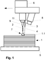
- the molded body 1 is according to Figure 1 built up in layers on the pressure plate 5 by melting off individual metal droplets from the starting material 2 fed through the material feed device 9, here a metal wire made of titanium, and depositing them in a molten state at the generating site 7 within the layer 1.1.
- the protective gas supply device 11 with an outflow opening formed in a ring shape around the material supply device 9 generates a protective gas jacket (not shown) around the generating site 7.
- the coolant 4 is fed in a targeted manner in the feed direction (illustrated by the arrow) to the generating site 7 on the layer 1.1 or the separated, still molten drop of the material 2, so that it solidifies as part of the layer 1.1.
- the layer thicknesses are shown greatly enlarged.
- the temperature-sensitive camera 8 captures the temperature of the layer 1.1 in the vicinity of the generating site 7.
- the evaluation and control unit 6 enables the impact position of the coolant 4 and the coolant mass flow to be checked.
- Figure 2 shows the processing module with the nozzles 10 arranged in a circle around the protective gas supply device 11 and the material supply device 9.
- FIG. 3 A processing module with only one nozzle 10 is shown, the processing module being rotatable about the axis of rotation 12.
- the fluid supply device 3 is designed in such a way that the coolant 4 is sprayed onto the layers 1.2 below the layer 1.1 to be built up by means of the nozzles 10, so that the active cooling does not take place from the top side but from the side walls of the molded body 1.
Landscapes
- Engineering & Computer Science (AREA)
- Manufacturing & Machinery (AREA)
- Chemical & Material Sciences (AREA)
- Materials Engineering (AREA)
- Mechanical Engineering (AREA)
- Physics & Mathematics (AREA)
- Optics & Photonics (AREA)
- Plasma & Fusion (AREA)
- Automation & Control Theory (AREA)
- Analytical Chemistry (AREA)
- Powder Metallurgy (AREA)
- Laser Beam Processing (AREA)
Description
- Die Erfindung betrifft ein Bearbeitungsmodul und seiner Verwendung in einer Vorrichtung zur Herstellung von komplexen metallischen Bauteilen z. B. aus einem metallischen Werkstoffgemisch, mittels additiv-generativer Fertigung, wobei blech-, draht- oder pulverförmiger metallhaltiger Werkstoff aufgeschmolzen und schichtweise aufgetragen wird.
- Additiv-generative Fertigungsverfahren nehmen bereits heute eine bedeutende Stellung innerhalb der Fertigungstechnologien ein. Der limitierende Faktor in der Prozessgeschwindigkeit ist hierbei aber oftmals das System aus Schutzgasabdeckung und Kühlung. Da der Werkstoff bei generativen Fertigungsverfahren in der Regel aufgeschmolzen wird, können sehr hohe Prozesstemperaturen auftreten. Dies tritt insbesondere bei der Verwendung metallischer Werkstoffe auf, bei denen die Schmelztemperaturen bis zu 2000°C und höher betragen. Infolgedessen entsteht zum einen eine erhebliche Erwärmung des Gesamtsystems resultierend in veränderten Gefügeeigenschaften der abgeschiedenen Metallschichten und zum anderen tritt eine erhöhte Oxidationsneigung auf, die wiederum die Eigenschaften des generierten Bauteiles, insbesondere in den Randzonen, beeinflussen kann.
- Aus diesem Grunde gibt es Vorschläge, das Bauteil während seiner generativen Fertigung zu kühlen, beispielsweise mittels Eintauchens in eine Kühlflüssigkeit, wie in
US 2015/0108095 A1 beschrieben. Diese Lösung zur Kühlung besitzt jedoch den Nachteil eines sehr großen gerätetechnischen Aufwandes, wobei das gesamte Bauteil zum Schluss von Flüssigkeit umschlossen ist. Weiterhin kühlt das Fluid das Bauteil von seinen Außenwänden her, sodass bei massiven Bauteilen der Wärmeabtransport über sehr große Entfernungen erfolgen muss, was die Abkühlrate senkt. Außerdem weist eine Kühlung mit einer Flüssigkeit den Nachteil auf, dass das Bauteil nach Fertigstellung nass ist und getrocknet werden muss. Auch kann es speziell bei additiv gefertigten Körpern dazu kommen, dass geschlossene Hohlräume generiert werden, in denen z. B. Reste der Kühlflüssigkeit verbleiben. - Auch das aus anderen Verfahren (z. B. der mechanischen Bearbeitung) bekannte Aufspritzen von Flüssigkeiten zur Erzielung einer schnellen Abkühlung weist diese Nachteile auf.
- Weiterhin wird vorgeschlagen, mit einer gekühlten (verlorenen oder wiederverwendbaren) Druckplatte zu arbeiten. Hier sind die o. g. Nachteile des begrenzten Wärmeabtransportes aufgrund der Kühlung des Bauteils nur von seiner mit der Druckplatte im thermischen Kontakt stehenden Wand bzw. Aufstandsfläche noch stärker ausgeprägt.
- Aus dem Stand der Technik ist ebenso bekannt, mit einem starken Gasstrom zu kühlen.
DE 10 2013 022 056 A1 offenbart eine Vorrichtung zum Schweißen mittels Lichtbogen, die z. B. mit einer Ringdüse einen Kaltgasstrom um den Lichtbogen erzeugt, der denselben auch einschnürt. Nachteilig daran ist, dass der Gasstrom für eine ausreichende Kühlwirkung so stark sein muss, dass er die Schutzgaswirkung beim Auftragen oder sogar den Lichtbogen selbst stört. -
US 2015/041025 A1 zeigt eine Vorrichtung zur additiven Fertigung, bei welcher eine Kühlgas-Düse dem Bearbeitungsstrahl, welcher auf der Werkstückoberfläche ein Schmelzbad erzeugt, nachläuft. Somit erlaubt ein durch die Kühlgas-Düse auf die noch heiße Oberfläche aufgebrachtes Kühlgas eine Zwangskühlung eines punktuellen Bereichs in Vorschubrichtung hinter dem Bearbeitungsstrahl. Zwar ist durch die räumliche Trennung des Ortes der Zwangskühlung vom Ort der Schmelzbaderzeugung eine Störung z. B. des Lichtbogens durch das Kühlgas vermieden, doch erlaubt diese Vorrichtung aufgrund dessen auch nur eingeschränkte Kühlmöglichkeiten. - Weiterhin ist es wichtig, wie bereits ausgeführt, insbesondere bei der Verwendung metallischer Werkstoffe, bei denen sich aufgrund der hohen Prozesstemperaturen eine verstärkte Oxidation feststellen lässt, die generative Fertigung unter Schutzgasatmosphäre durchzuführen. Allgemein bekannt ist, den Bauraum, in welchem das Bauteil gefertigt wird, mit Schutzgas zu spülen, wie z. B. in
DE 196 49 865 C1 oderCN 104 353 832 A beschrieben. Hierfür ist jedoch ein erheblicher technischer Aufwand zur Abdichtung des Bauraumes notwendig, wie speziell am Beispiel derWO 2012/134299 A2 ersichtlich wird. -
US 2015/108094 A1 bezieht sich auf ein Bearbeitungsmodul für eine Vorrichtung zur additiven Fertigung eines Formkörpers umfassend eine Werkstoffzuführungseinrichtung, eine Schutzgaszuführungseinrichtung, welche eine ringförmig um die Werkstoffzuführungseinrichtung angeordnete Ausströmöffnung aufweist, und eine Fluidzuführungseinrichtung zur Zuführung eines Fluids in Form von Schutzgas, wobei die unmittelbar mit der Werkstoffzuführungseinrichtung verbunden, ringförmig um diese angeordneten Düsen als Ringdüsen ausgeführt sind. Bei Betrieb des Schweißbrenners entsteht daher ein ununterbrochener, konzentrischer Fluidschleier um den in Zentrum befindlichen Generierwirkort. - Aufgabe der Erfindung ist es, ein Bearbeitungsmodul für eine Vorrichtung zur additiven Fertigung eines metallische Formkörpers durch lagenweisen Aufbau eines geschmolzenen blech-, draht- oder pulverförmigen Werkstoffes Formkörper bereit zu stellen, mittels dessen während der Abscheidung der Schichten sowohl eine punktuell genaue Kühlung in einem beliebig vorgebbaren Bereich des Schmelzbades als auch eine vollständige Schutzgasabdeckung, bei welcher der technische Aufwand für eine hermetische Abdichtung des Bauraumes gegen die Umgebung entfallen kann, möglich sein soll.
- Die Lösung dieser Aufgabe erfolgt mit einem Bearbeitungsmodul gemäß Patentanspruch 1 sowie mit der Verwendungen des genannten Bearbeitungsmoduls gemäß den Patentansprüchen 6 bis 8; zweckmäßige Ausgestaltungen der Erfindung finden sich in den Unteransprüchen.
- Unter dem Begriff "Bearbeitungsmodul" wird hierin allgemein diejenige Baugruppe einer Vorrichtung für die additiv-generative Fertigung verstanden, die zumindest eine Werkstoffzuführungseinrichtung, z. B. ein Drahtzuführmodul, umfasst, wobei der mit dieser den aufzubauenden Schichten zugeführte, blech-, draht- oder pulverförmige Werkstoff mittels Energiezufuhr, z. B. über einen Laserstrahl oder einen Lichtbogen, aufschmelzbar ist. Die Energiequelle zur Erzeugung der Energiezufuhr kann hierbei Bestandteil des Bearbeitungsmoduls sein, sie kann aber auch räumlich getrennt, z. B. außerhalb eines umhausten Fertigungs-Bauraumes, angeordnet sein.
- Das erfindungsgemäße Bearbeitungsmodul ist demnach vorgesehen als Baugruppe für eine Vorrichtung zur additiven Fertigung eines metallischen Formkörpers aus mindestens einem schmelzbaren, draht-, band-, pulver- oder blechförmigen Werkstoff, der mittels Energiezufuhr (z. B. mittels Lichtbogen oder Laserstrahl) aufgeschmolzen und in schmelzflüssiger Phase in einem Generierwirkort auf dem bereits fertiggestellten Teil des herzustellenden Formkörpers abgeschieden wird, wobei der schmelzflüssige Werkstoff nach dem Abscheiden durch gezielte Kühlung unter Ausbildung eines festen Metalls erstarrt.
- Unter Generierwirkort wird die Position, d. h. ein lokal begrenzte Bereich, auf der Oberfläche des bereits fertiggestellten Teils des Formkörpers verstanden, an der schmelzflüssiger Werkstoff auf die Oberfläche aufgebracht wird.
- Nach Maßgabe der Erfindung umfasst das Bearbeitungsmodul neben der Werkstoffzuführungseinrichtung eine ringförmig um die Werkstoffzuführungseinrichtung ausgebildete Schutzgaszuführeinrichtung sowie eine Fluidzuführungseinrichtung zur Zuführung mindestens eines Fluids an eine Position auf oder unmittelbar neben einem auf der Oberfläche des gerade in Fertigung befindlichen Formkörpers ausgebildeten Schmelzbades.
- Unter dem hierin verwendeten Begriff "Schutzgas" wird allgemein ein Gas verstanden, welches geeignet ist, die Oxidation von schmelzflüssigem Metall zu verhindern, beispielsweise ein Edelgas wie Argon, ein Prozessgas wie Kohlendioxid oder ein Inertgas wie Stickstoff.
- Die Schutzgaszuführeinrichtung kann eine ringförmige Ausströmöffnung oder mehrere, einen Ring ausbildende Ausströmöffnungen aufweisen. Aufgrund dieser ringförmigen Ausgestaltung um die Werkstoffzuführungseinrichtung ist es mittels der Schutzgaszuführeinrichtung ermöglicht, eine lokale Schutzgasabdeckung, d. h. ein im Wesentlichen zylinderförmiges, mit Schutzgas ausgefülltes Volumen (Schutzgasmantel), um den zugeführten Werkstoff und den Generierwirkort zu legen.
- Die Fluidzuführungseinrichtung weist vorzugsweise mehrere Düsen (d. h. Ausströmöffnungen für das Fluid) auf, die derart räumlich benachbart zu der Werkstoffzuführungseinrichtung des Bearbeitungsmoduls angeordnet sind, dass der Formkörper auf seiner Oberfläche an einer vorgebbaren Position unmittelbar neben einem Schmelzbad punktuell oder partiell mit dem Fluid anströmbar oder das Schmelzbad vollständig mit anströmendem Fluid einschließbar ist.
- Hierbei kann der Teil der Oberfläche des Formkörpers, der mit dem Fluid anströmbar ist, eine beliebige Orientierung in Bezug zur Horizontalen aufweisen. Beispielsweise kann der mit dem Fluid angeströmte Teil der Oberfläche horizontal ausgerichtet sein (d. h., das Fluid trifft neben dem Schmelzbad auf den Formkörper). Der mit dem Fluid angeströmte Oberflächenbereich des Formkörpers kann auch lotrecht ausgerichtet sein (d. h., das Fluid trifft auf eine Seitenwand in einem Bereich unterhalb des Schmelzbades auf den Formkörper).
- Erfindungsgemäß ist die Position der punktuellen oder partiellen Anströmung während der Fertigung beliebig variierbar, d. h., ein beispielsweise in einem Punkt auf der Oberfläche des Formkörpers auftreffender Strahl des Fluids ist in der Art mittels der Fluidzuführungseinrichtung steuerbar, dass der Auftreffpunkt um das auf der Oberfläche ausgebildete Schmelzbad rotieren, d. h. umlaufen, kann.
- Es kann auch vorgesehen sein, dass das Fluid in einem (ausgedehnten) Bereich auf der Oberfläche des Formkörpers auftritt, wobei der Bereich z. B. die Form eines geschlossenen Kreises oder eines Kreisbogenabschnittes aufweisen kann. Insbesondere können hierbei die Position des Kreisbogenabschnitts und/oder seine Ausdehnung, d. h. sein Zentriwinkel, während der Fertigung variieren.
- Das Fluid kann ein Kühlmittel, ein Prozessgas und/oder ein Schutzgas sein.
- Die Ansteuerung der Fluidzuführungseinrichtung, d. h. die konkrete Festlegung des mit dem Fluid zu bestrahlenden Oberflächenbereiches sowie der aus den Düsen ausströmende Fluidmassestrom, erfolgt z. B. bahngeneriert, d. h., Fluidmassestrom sowie Form und Position des zu bestrahlenden Oberflächenbereiches werden aufgrund der bei der Fertigung programmierten Bahn des Generierwirkortes innerhalb der lagenweise aufzubauenden Schichten festgelegt, wobei auch die Geometriebeschreibungsdaten des Formkörpers Einfluss finden können, um beispielsweise einen Kühlmittelmassestrom entsprechend einer Wandstärke oder Strukturdimensionen des Formkörpers zu positionieren und/oder zu skalieren.
- Für eine beschleunigte bzw. kontrollierte Abkühlung des in den Schichten abgeschiedenen schmelzflüssigen Werkstoffes ist mittels der Erfindung eine dem Generierwirkort nachlaufende, lokale Kühlung möglich (während der Generierwirkort zugleich von Schutzgas eingeschlossen wird). Ebenso ist eine gezielte Temperaturbehandlung, z. B. Abkühlung, des Bereiches auf der Formkörperoberfläche unmittelbar vor dem Generierwirkort möglich.
- Die Gefügebildung, d. h. das Ausbilden einer Mikrostruktur in einem aus einer metallhaltigen Schmelze gebildeten metallischen Werkstoffs (d. h. eines Metalls, einer Legierung oder eines anderen metallischen Stoffgemischs), erfolgt während des Erstarrens. Aufgrund einer mit dem erfindungsgemäßen Bearbeitungsmodul durchführbaren, gezielten, aktiven Kühlung, durch z. B. lokal mittels der Fluidzuführungseinrichtung zugeführten Prozessgases, kann die Gefügebildung kontrolliert werden, indem z. B. das Erstarrungsverhalten von bereits in der Schmelze gemischten Ausgangswerkstoffen gezielt durch die Temperaturführung beim Abkühlen und Erstarren der Schmelze (unter Ausbildung z. B. einer Legierung) gesteuert wird.
- Die Temperaturführung bei der additiven Fertigung, beispielsweise die Abkühlrate, kann mittels des erfindungsgemäßen Bearbeitungsmoduls während der Fertigung veränderlich sein, d. h., die Gefügebildung kann in weiten Grenzen durch die Temperaturführung mittels kontrollierter Zuführung von Kühlmittel eingestellt werden.
- Durch die Erfindung ist es folglich möglich, dass Bauteile aus maßgeschneiderten metallischen Gefügen hergestellt werden, indem wiederholt schmelzflüssiger Werkstoff von lediglich Tröpfchengröße abgeschieden und einer gezielten Erstarrung (dieser Tröpfchen) unterzogen wird, wobei aufgrund der Schutzgaszuführeinrichtung eine Oxidation der Metallschmelze zuverlässig unterbindbar ist.
- Die Schutzgaszuführeinrichtung ist dadurch vorteilhaft, dass ein lokal begrenzter "Schutzgasvorhang" um den schmelzflüssigen Werkstoff gelegt werden kann. Somit wird der technische Aufwand für einen gegen die Umgebung abzudichtenden Bauraum für die Vorrichtung zur generativen Fertigung entbehrlich, da der schichtweise Aufbau unter lokal aufgebauter Schutzgasatmosphäre durchführbar ist.
- Die Erfindung ist anwendbar auf bekannte additive Verfahren (wie z. B. Lasersintern, Laserschmelzen, formgebendes Schweißen, US-Schweißen etc.), mittels der einzelnen Schichten in unterschiedlicher Dicke von wenigen Mikrometern bis hin zu mehreren Millimetern mittels Abscheidens schmelzflüssiger Werkstoffe erzeugt werden können.
- Vorteile der Erfindung bestehen auch darin, dass ein gewünschtes Gefüge lokal erzeugbar ist. Damit können bisher gegebene, fertigungsbedingte Restriktionen im Erzeugungsprozess des Bauteils umgangen werden. Durch den lagenweisen Aufbau im Sinne der generativen Fertigung kann ein spezifisches Werkstoffsystem mit lokal definierten und auch lokal veränderlichen Eigenschaften erzeugt werden. Somit lassen sich innerhalb eines massiven Bauteils die spezifischen Werkstoffeigenschaften (aufgrund des lokal variierbaren Gefüges) verändern.
- Indem die gewünschte Werkstoffstruktur erst beim "Drucken" des Bauteils direkt erzeugt wird, ist eine sehr genaue Anpassung und Variation der jeweiligen Werkstoffstruktur in den Schichten bzw. lokalen Bereichen des Formkörpers ermöglicht, sodass ein massives Bauteil herstellbar ist, welches z. B. aufgrund des jeweils ausgewählten Gefüges in einzelnen Bereichen besonders fest ist.
- Gemäß einer Ausgestaltungsvariante der Erfindung umfasst die Fluidzuführungseinrichtung eine Düse, die in einer Ebene parallel zur Ebene der aufzubauenden Schicht um die Werkstoffzuführungseinrichtung rotierbar ist. Hierzu kann das Bearbeitungsmodul beispielsweise eine Rotationachse senkrecht zur aufzubauenden Schicht aufweisen, sodass durch eine Rotation des Bearbeitungsmoduls um diese Rotationsachse die Düse (in gleicher Weise) um die Rotationsachse drehbar ist.
- So kann vorteilhaft der Strahl des aus der Düse strömenden Kühlmittels auf eine beliebige Position auf der Oberfläche des Formkörpers neben dem schmelzflüssig abgeschiedenen Werkstoff ausgerichtet werden, wobei z. B. bei einem wellenförmigen Verlauf der Bahn des Generierwirkortes auf der Formkörperoberfläche die Kühlung stets exakt auf den Bereich "hinter" dem Schmelzbad positionierbar ist.
- Gemäß einer anderen Ausgestaltungsvariante der Erfindung umfasst die Fluidzuführungseinrichtung mehrere Düsen, die ringförmig um die Werkstoffzuführungseinrichtung angeordnet sind. Somit ist auf der Formkörperoberfläche ein ringförmig um das Schmelzbad ausgebildeter Bereich kühlbar.
- Insbesondere kann vorgesehen sein, dass jede der Düsen mittels eines jeweils einzeln ansteuerbaren Ventiles geöffnet oder geschlossen werden kann. So ist es z. B. möglich, nur jeweils aus derjenigen Düse Kühlmittel strömen zu lassen, die in Vorschubrichtung des Bearbeitungsmoduls hinter der Werkstoffzuführungseinrichtung angeordnet ist.
- Es kann auch vorgesehen sein, dass während des Betriebes des Bearbeitungsmoduls aus dem Fluidzuführungseinrichtung sowohl ein Kühlmittel als auch ein Prozess- oder ein Schutzgas strömt, d. h., aus einem Teil der Düsen strömt Kühlmittel und aus dem restlichen Teil der Düsen strömt Prozess- oder Schutzgas. Hierfür kann jede der Düsen mit einem jeweils einzeln ansteuerbaren Umschaltventil verbunden sein, wobei die Umschaltventile jeweils mit einer Kühlmittelzufuhrleitung und einer Prozess- bzw. Schutzgaszufuhrleitung verbunden sind. So kann aus jeder der Düsen wahlweise Kühlmittel oder Prozess- bzw. Schutzgas strömen.
- Gemäß einer weiteren Ausführungsform kann anstelle des Umschaltventils ein Mischer bzw. eine Mischbatterie eingesetzt sein, mittels der eine definierte Mischung aus Schutzgas und Kühlmittel erzeugbar ist, wobei für jede der Düsen das Mischungsverhältnis identisch oder auch unterschiedlich vorgebbar sein kann.
- Die Erfindung kann derart ausgebildet sein, dass als Kühlmittel für die gezielte Kühlung des abgeschiedenen schmelzflüssigen Werkstoffs ein gasförmiges Kühlmittel, z. B. ein Schutzgas, ein Kühlmittel in fester Phase, z. B. Kohlendioxidpellets bzw. pulverförmiger Kohlendioxidschnee, oder ein Aerosol verwendet wird.
- Der Vorteil von Trockeneis bzw. Aerosolen ist ihr zusätzlicher Beitrag zur Wärmeabfuhr aufgrund Aufnahme von latenter Wärme bei der Sublimation bzw. Verdampfung, wobei der Formkörper im Wesentlichen trocken bleibt.
- Es kann auch vorgesehen sein, dass als Kühlmittel eine Flüssigkeit, z. B. eine korrosionsverhütende Flüssigkeit oder eine kryogene Flüssigkeit (d. h. ein bei einer Temperatur unterhalb von -150°C verflüssigtes Gas), verwendet wird.
- Gemäß einer weiteren Ausführungsform umfasst das Bearbeitungsmodul ein temperatursensitives Kamerasystem, mittels dessen in einem Bereich um den Generierwirkort die Temperatur der Formkörperoberfläche ortsaufgelöst erfassbar ist, sowie eine mit dem Kamerasystem und den einzeln ansteuerbaren Düsen bzw. einem Antrieb zur Rotation des Bearbeitungsmoduls um eine senkrecht zu der im Aufbau befindlichen Schicht ausgerichteten Rotationsachse verbundene Auswerte- und Steuerungseinheit. Hierbei ist die Auswerte- und Steuerungseinheit derart eingerichtet, dass sie den Kühlmittelstrom, d. h. die Positionierung, räumliche Verteilung und/oder den Massestrom, basierend auf den von dem Kamerasystem erfassten Temperaturwerten auf der Formkörperoberfläche steuert.
- Es kann vorgesehen sein, dass das Bearbeitungsmodul eine Absaugvorrichtung, z. B. in Form eines Saugrüssels oder einer um die Fluidzuführungseinrichtung (in radialer Richtung außerhalb derselben) angeordneten Ringdüse, umfasst, mittels der z. B. verdampfte, als Kühlmittel verwendete Flüssigkeiten auffangbar sind, um sie beispielsweise (nach Reinigung und/oder Abkühlung) erneut zur Kühlung zu verwenden.
- Insbesondere ist es bei dieser Ausführungsform möglich, mit einem starkem Kühlmittelstrom zu kühlen, da beispielsweise überschüssige, nicht verdampfte Kühlflüssigkeit mittels der Absaugvorrichtung sofort wieder absaugbar ist, sodass der Formkörper trocken bleibt.
- Die Absaugvorrichtung kann auch in Form einer um die Werkstoffzuführungseinrichtung angeordneten Ringdüse ausgebildet sein, mittels der z. B. verdampfte Ausgangswerkstoffe und/oder Schweißrauch absaugbar sind. So ist in vorteilhafter Weise eine Beeinträchtigung der ortsaufgelösten Temperaturmessung mittels des temperatursensitiven Kamerasystems während der Schichtabscheidung reduziert.
- Die Erfindung kann weiter derart ausgebildet sein, dass das Bearbeitungsmodul um eine parallel zur Ebene der aufzubauenden Schicht ausgerichtete Achse kipp- bzw. drehbar ist.
- Die Erfindung wird nachfolgend anhand von Ausführungsbeispielen näher erläutert. Dazu zeigen in schematischer Darstellung die
- Figur 1:
- das Bearbeitungsmodul während einer additiven Fertigung;
- Figur 2:
- eine erste Ausgestaltungsvariante des Bearbeitungsmoduls in Schrägdraufsicht
- Figur 3:
- eine zweite Ausgestaltungsvariante des Bearbeitungsmoduls in Schrägdraufsicht; und
- Figur 4:
- eine dritte Ausgestaltungsvariante des Bearbeitungsmoduls im Querschnitt.
- Der Formkörper 1 wird gemäß
Figur 1 auf der Druckplatte 5 schichtweise aufgebaut, indem von dem durch die Werkstoffzuführungseinrichtung 9 zugeführten Ausgangswerkstoff 2, hier einem Metalldraht aus Titan, jeweils einzelne Metalltröpfchen abgeschmolzen und schmelzflüssig am Generierwirkort 7 innerhalb der Schicht 1.1 abgeschieden werden. - Die Schutzgaszufuhreinrichtung 11 mit einer ringförmig um die Werkstoffzuführungseinrichtung 9 ausgebildeten Ausströmöffnung erzeugt einen Schutzgasmantel (nicht dargestellt) um den Generierwirkort 7.
- Mittels der Fluidzuführungseinrichtung 3 wird das Kühlmittel 4 gezielt in Vorschubrichtung (durch den Pfeil veranschaulicht) dem Generierwirkort 7 nachlaufend auf die Schicht 1.1 bzw. dem abgeschiedenen, noch schmelzflüssigen Tropfen des Werkstoffs 2 zugeführt, sodass er als Teil der Schicht 1.1 erstarrt. In diesem Beispiel sind die Schichtdicken stark vergrößert dargestellt.
- Die temperatursensitive Kamera 8 erfasst die Temperatur der Schicht 1.1 in der Umgebung des Generierwirkortes 7. Die Auswerte- und Steuerungseinheit 6 ermöglicht die Kontrolle der Auftreffposition des Kühlmittels 4 sowie den Kühlmittelmassestrom.
-
Figur 2 zeigt das Bearbeitungsmodul mit den kreisförmig um die Schutzgaszufuhreinrichtung 11 und die Werkstoffzuführungseinrichtung 9 angeordneten Düsen 10. - In
Figur 3 ist ein Bearbeitungsmodul mit nur einer Düse 10 dargestellt, wobei das Bearbeitungsmodul um die Rotationsachse 12 drehbar ist. - In einer dritten Ausgestaltungsvariante des Bearbeitungsmoduls gemäß
Figur 4 ist die Fluidzuführungseinrichtung 3 derart ausgebildet, dass das Kühlmittel 4 mittels der Düsen 10 auf die Schichten 1.2 unterhalb der aufzubauenden Schicht 1.1 gesprüht wird, sodass die aktive Kühlung nicht von der Oberseite, sondern den Seitenwänden des Formkörpers 1 her erfolgt. -
- 1
- Formkörper
- 1.1
- Schicht
- 1.2
- Schicht
- 2
- Ausgangswerkstoff
- 3
- Fluidzuführungseinrichtung
- 4
- Kühlmittel
- 5
- Druckplatte
- 6
- Auswerte- und Steuerungseinheit
- 7
- Generierwirkort
- 8
- temperatursensitives Kamerasystem
- 9
- Werkstoffzuführungseinrichtung
- 10
- Düse
- 11
- Schutzgaszufuhreinrichtung
- 12
- Rotationsachse
Claims (8)
- Bearbeitungsmodul für eine Vorrichtung zur additiven Fertigung eines Formkörpers (1) durch Abscheiden eines schmelzbaren, blech-, draht- oder pulverförmigen Ausgangswerkstoffes (2) in einem innerhalb von einzelnen, jeweils aufeinanderfolgenden Schichten (1.1) fortbewegten Generierwirkort (7), wobei das Bearbeitungsmodul eine Werkstoffzuführungseinrichtung (9), eine Schutzgaszufuhreinrichtung (11), die eine oder mehrere ringförmig um die Werkstoffzuführungseinrichtung (9) angeordnete Ausströmöffnungen aufweist, sowie eine Fluidzuführungseinrichtung (3) zur Zuführung eines Fluids in Form von Kühlmittel (4) und/oder Schutzgas umfasst dadurch gekennzeichnet, dass die Fluidzuführungseinrichtung (3) eine oder mehrere Düsen (10) aufweist, die derart räumlich benachbart zu der Werkstoffzuführungseinrichtung (9) angeordnet sind, dass der Formkörper (1) auf seiner Oberfläche unmittelbar neben dem Generierwirkort (7) an einer Position, die jeweils veränderlich vorgebbar ist, punktuell oder partiell mit dem Fluid anströmbar ist, wobei- die Fluidzuführungseinrichtung (3) eine Düse (10) umfasst, die in einer Ebene parallel zu der zu fertigenden Schicht (1.1) um die Werkstoffzuführungseinrichtung (9) rotierbar ist, oder- die Fluidzuführungseinrichtung (3) mehrere Düsen (10) umfasst, die ringförmig um die Werkstoffzuführungseinrichtung (9) angeordnet sind, wobei ein jeweils durch die Düsen (10) strömender Fluidmassestrom für jede Düse (10) separat steuerbar ist.
- Bearbeitungsmodul nach Anspruch 1, dadurch gekennzeichnet, dass die Düsen (10) jeweils mittels eines Umschaltventils und/oder Mischers mit einer Schutzgas- und einer Kühlmittelzuleitung verbunden sind.
- Bearbeitungsmodul nach Anspruch 1 oder 2, dadurch gekennzeichnet, dass zumindest die Fluidzuführungseinrichtung (3) um eine senkrecht zu der zu fertigenden Schicht (1.1) ausgerichtete Rotationsachse (12) drehbar ist.
- Bearbeitungsmodul nach einem der vorstehenden Ansprüche, dadurch gekennzeichnet, dass es ferner ein temperatursensitives Kamerasystem (8), mittels welchem in einem Bereich um den Generierwirkort (7) die Temperatur der Formkörperoberfläche ortsaufgelöst erfassbar ist, sowie eine mit dem Kamerasystem und der Fluidzuführungseinrichtung (3) verbundene Auswerte- und Steuerungseinheit (6), die derart eingerichtet ist, dass die Fluidzuführungseinrichtung (3) basierend auf den von dem Kamerasystem erfassten Temperaturwerten steuerbar ist, aufweist.
- Bearbeitungsmodul nach einem der vorstehenden Ansprüche, dadurch gekennzeichnet, dass es eine Absaugeinrichtung zum Absaugen von Fluid und/oder Rauchgasen von der Formkörperoberfläche umfasst.
- Verwendung des Bearbeitungsmoduls nach einem der vorstehenden Ansprüche zur additiven Fertigung eines Formkörpers (1), dadurch gekennzeichnet, dass das Kühlmittel (4) ein Prozessgas ist.
- Verwendung des Bearbeitungsmoduls nach einem der Ansprüche 1 bis 5 zur additiven Fertigung eines Formkörpers (1), dadurch gekennzeichnet, dass das Kühlmittel ein Aerosol ist.
- Verwendung des Bearbeitungsmoduls nach einem der Ansprüche 1 bis 5 zur additiven Fertigung eines Formkörpers (1), dadurch gekennzeichnet, dass das Kühlmittel Trockeneis in Form von Pulver oder Granulat ist.
Applications Claiming Priority (2)
| Application Number | Priority Date | Filing Date | Title |
|---|---|---|---|
| DE102015117238.0A DE102015117238A1 (de) | 2015-10-09 | 2015-10-09 | Bearbeitungsmodul für eine Vorrichtung zur additiven Fertigung |
| PCT/DE2016/100461 WO2017059842A1 (de) | 2015-10-09 | 2016-10-04 | Bearbeitungsmodul für eine vorrichtung zur additiven fertigung |
Publications (2)
| Publication Number | Publication Date |
|---|---|
| EP3359320A1 EP3359320A1 (de) | 2018-08-15 |
| EP3359320B1 true EP3359320B1 (de) | 2019-12-25 |
Family
ID=57396236
Family Applications (1)
| Application Number | Title | Priority Date | Filing Date |
|---|---|---|---|
| EP16801372.0A Active EP3359320B1 (de) | 2015-10-09 | 2016-10-04 | Bearbeitungsmodul für eine vorrichtung zur additiven fertigung und verwendung dieses bearbeitungsmoduls zur additiven fertigung eines formkörpers |
Country Status (5)
| Country | Link |
|---|---|
| US (1) | US11285567B2 (de) |
| EP (1) | EP3359320B1 (de) |
| DE (1) | DE102015117238A1 (de) |
| ES (1) | ES2776630T3 (de) |
| WO (1) | WO2017059842A1 (de) |
Cited By (2)
| Publication number | Priority date | Publication date | Assignee | Title |
|---|---|---|---|---|
| DE102021101846A1 (de) | 2021-01-27 | 2022-07-28 | Rheinisch-Westfälische Technische Hochschule (RWTH) Aachen, Körperschaft des öffentlichen Rechts | Verfahren für die generative fertigung von bauteilen |
| US12571223B2 (en) | 2023-03-28 | 2026-03-10 | Peri Se | Device and method for additive manufacturing of a component |
Families Citing this family (43)
| Publication number | Priority date | Publication date | Assignee | Title |
|---|---|---|---|---|
| US20180147628A1 (en) * | 2016-11-29 | 2018-05-31 | Neeraj Saxena | Laser deposition and ablation for additive and ablation manufacturing |
| DE102017103066A1 (de) | 2017-02-15 | 2018-08-16 | Flottweg Se | Verfahren zum Herstellen eines metallischen Werkstücks |
| JP6822881B2 (ja) * | 2017-03-27 | 2021-01-27 | 株式会社神戸製鋼所 | 積層造形物の製造方法及び製造システム |
| US20240157435A1 (en) * | 2017-06-30 | 2024-05-16 | Norsk Titanium As | Solidification refinement and general phase transformation control through application of in situ gas jet impingement in metal additive manufacturing |
| KR102580867B1 (ko) * | 2017-06-30 | 2023-09-19 | 노르스크 티타늄 아에스 | 금속 적층 가공에 있어서의 현위치 가스 제트 충돌의 적용을 통한 응고 미세화 및 일반적인 상 변태 제어 |
| US11752547B2 (en) | 2017-06-30 | 2023-09-12 | Norsk Titanium As | Solidification refinement and general phase transformation control through application of in situ gas jet impingement in metal additive manufacturing |
| US11020822B2 (en) * | 2017-08-10 | 2021-06-01 | Formalloy Technologies, Inc. | Active cooling of additive manufacturing process |
| DE102017221909A1 (de) | 2017-12-05 | 2019-06-06 | MTU Aero Engines AG | Schichtbauvorrichtung zur additiven Herstellung zumindest eines Bauteilbereichs eines Bauteils, Strömungsleiteinrichtung für eine Schichtbauvorrichtung und Verfahren zum Betreiben einer Schichtbauvorrichtung |
| DE102017222888A1 (de) * | 2017-12-15 | 2019-06-19 | Fraunhofer-Gesellschaft zur Förderung der angewandten Forschung e.V. | Verfahren zur Beeinflussung der Mikrostruktur eines Zusatzwerkstoffgefüges eines Zusatzwerkstoffs, der beim schichtweisen Laserauftragsschweißen auf ein Substrat oder mindestens einer bereits aufgebrachten Schicht des Zusatz-werkstoffs und/oder der Vermeidung einer Randzonenversprödung von dabei aufgetragenem Zusatzwerkstoff |
| DE102018125605A1 (de) * | 2018-10-16 | 2020-04-16 | Air Liquide Deutschland Gmbh | Verfahren zur additiven Fertigung eines Bauteils |
| US20200130268A1 (en) * | 2018-10-29 | 2020-04-30 | Hamilton Sundstrand Corporation | Enhanced cooling during additive manufacturing |
| US11065815B2 (en) * | 2018-12-18 | 2021-07-20 | General Electric Company | Powder dispensing assembly for an additive manufacturing machine |
| DE102018222409A1 (de) | 2018-12-20 | 2020-06-25 | MTU Aero Engines AG | Schichtbauvorrichtung zur additiven Herstellung zumindest eines Bauteilbereichs eines Bauteils, Strömungsleiteinrichtung für eine Schichtbauvorrichtung und Verfahren zum Betreiben einer Schichtbauvorrichtung |
| CN109848559B (zh) * | 2019-01-16 | 2021-04-27 | 东南大学 | 一种含有移动气氛室的激光头以及激光增材有色金属的方法 |
| JP7354489B2 (ja) * | 2019-03-19 | 2023-10-03 | ニデックマシンツール株式会社 | 三次元積層装置及び三次元積層方法 |
| DE112019007022B4 (de) | 2019-04-16 | 2023-03-30 | Mitsubishi Electric Corporation | Schutzgasdüse zur Metallbildung und Lasermetallbildungsvorrichtung |
| EP3741489A1 (de) * | 2019-05-24 | 2020-11-25 | Linde GmbH | Vorrichtung zur reinigung und kühlung eines werkstücks während der generativen drahtlichtbogenfertigung (waam) |
| FR3100001B1 (fr) * | 2019-08-22 | 2023-04-14 | Safran Aircraft Engines | Procede de fabrication additive d’une piece de turbomachine |
| JP2023502741A (ja) * | 2019-11-21 | 2023-01-25 | ノルスク・チタニウム・アーエス | 指向性エネルギー堆積における歪み軽減 |
| US12048965B2 (en) * | 2019-11-21 | 2024-07-30 | Norsk Titanium As | Distortion mitigation in directed energy deposition |
| JP2021085060A (ja) * | 2019-11-27 | 2021-06-03 | 三菱重工業株式会社 | 三次元造形装置及び三次元造形方法 |
| KR102207314B1 (ko) * | 2020-06-16 | 2021-01-25 | 주식회사 바이오프렌즈 | Fdm방식의 3d 프린터용 노즐 장치 |
| US11897030B2 (en) * | 2020-07-08 | 2024-02-13 | Air Products And Chemicals, Inc. | Method and system for improved temperature control for additive manufacturing |
| EP3984678A1 (de) * | 2020-10-13 | 2022-04-20 | Linde GmbH | Schweisseinrichtung mit düsenvorrichtung zum kühlen eines werkstücks während des schweissvorgangs |
| DE112020007684T5 (de) | 2020-10-15 | 2023-08-03 | Mitsubishi Electric Corporation | Verfahren zur additiven fertigung, vorrichtung zur additiven fertigung und system zur additiven fertigung |
| KR102331858B1 (ko) | 2021-01-07 | 2021-12-01 | 삼성엔지니어링 주식회사 | 출력물 표면 정리형 건설용 3d 프린터 |
| KR102331860B1 (ko) * | 2021-01-07 | 2021-12-01 | 삼성엔지니어링 주식회사 | 출력물 표면 처리형 건설용 3d 프린터 |
| CN112975054A (zh) * | 2021-02-22 | 2021-06-18 | 西安铂力特增材技术股份有限公司 | 电弧增材制造过程中零件表面温度控制装置及控制方法 |
| CN112809183A (zh) * | 2021-03-15 | 2021-05-18 | 中国人民解放军空军工程大学 | 增材制造金属冷却方法 |
| CN112935642B (zh) * | 2021-03-25 | 2023-06-30 | 南京航空航天大学 | 一种辅助电弧增材制造的主动冷却系统 |
| JP7666098B2 (ja) * | 2021-04-22 | 2025-04-22 | セイコーエプソン株式会社 | 三次元造形装置 |
| CN113263242A (zh) * | 2021-05-08 | 2021-08-17 | 南京航空航天大学 | 一种变截面结构电弧增材制造过程冷却装置及方法 |
| CN113333998B (zh) * | 2021-05-25 | 2023-10-31 | 绍兴市上虞区武汉理工大学高等研究院 | 一种基于协作机器人的自动化焊接系统及方法 |
| DE102021205815A1 (de) * | 2021-06-09 | 2022-12-15 | Siemens Energy Global GmbH & Co. KG | Konvektionskühler für Wire Arc Additiv Manufacturing |
| EP4116014A1 (de) * | 2021-07-08 | 2023-01-11 | Linde GmbH | Kühlsystem für die additive herstellung |
| CN113579249A (zh) * | 2021-07-29 | 2021-11-02 | 浙江工业大学 | 激光增材制造镍基合金过程中抑制Laves相析出的方法 |
| CN114701159B (zh) * | 2022-04-22 | 2025-09-19 | 深圳市创想三维科技股份有限公司 | 散热装置及3d打印设备 |
| DE102022116557A1 (de) * | 2022-07-02 | 2024-01-04 | HPL Technologies GmbH | Kühlstation für ein mittels Auftragschweißen beschichtetes und abzuschleifendes Werkstück, sowie ein Kühlverfahren für ein beschichtetes und abzuschleifendes Werkstück |
| WO2024081658A2 (en) * | 2022-10-10 | 2024-04-18 | Relativity Space, Inc. | Additive manufacturing modular end effector assembly |
| AU2024201409A1 (en) * | 2023-03-03 | 2024-09-19 | Relativity Space, Inc. | Systems and Methods for Welding Using Cryogenic Sources |
| CN117798384A (zh) * | 2023-12-27 | 2024-04-02 | 沈阳精合数控科技开发有限公司 | 一种同轴激光沉积中的吹气冷却系统和方法 |
| CN118682240A (zh) * | 2024-07-24 | 2024-09-24 | 深圳职业技术大学 | 一种基于干冰颗粒的电弧熔丝增材制造系统及方法 |
| CN120715389B (zh) * | 2025-07-09 | 2026-01-30 | 赣州永邦新能源有限公司 | 一种锂电池的自动生产装置 |
Family Cites Families (43)
| Publication number | Priority date | Publication date | Assignee | Title |
|---|---|---|---|---|
| US2799769A (en) * | 1955-09-26 | 1957-07-16 | Liquid Carbonic Corp | Shielding gas supply assembly for arc welding torch |
| US3575568A (en) * | 1967-06-08 | 1971-04-20 | Rikagaku Kenkyusho | Arc torch |
| DE3400111C1 (de) * | 1984-01-04 | 1985-08-29 | Fraunhofer-Gesellschaft zur Förderung der angewandten Forschung e.V., 8000 München | Vorrichtung zum automatischen Auswechseln von Schweissbrennern in einem Industrieroboterschweisssystem |
| US4902871A (en) * | 1987-01-30 | 1990-02-20 | Hypertherm, Inc. | Apparatus and process for cooling a plasma arc electrode |
| CA2037660C (en) * | 1990-03-07 | 1997-08-19 | Tadashi Kamimura | Methods of modifying surface qualities of metallic articles and apparatuses therefor |
| DE9013943U1 (de) * | 1990-10-06 | 1991-01-03 | Trumpf GmbH & Co, 7257 Ditzingen | Laserdüse |
| FR2685922B1 (fr) * | 1992-01-07 | 1995-03-24 | Strasbourg Elec | Buse coaxiale de traitement superficiel sous irradiation laser, avec apport de materiaux sous forme de poudre. |
| JP2677763B2 (ja) * | 1993-04-13 | 1997-11-17 | アレクサンダー ビンツェル ゲゼルシャフト ミット ベシュレンクテル ハフツング ウント コンパニー コマンディートゲゼルシャフト | アーク溶接又はアーク切断用のトーチ |
| US5486676A (en) * | 1994-11-14 | 1996-01-23 | General Electric Company | Coaxial single point powder feed nozzle |
| JP3420658B2 (ja) * | 1995-06-30 | 2003-06-30 | 株式会社東芝 | ティグ溶接方法およびその溶接トーチ |
| US6046426A (en) * | 1996-07-08 | 2000-04-04 | Sandia Corporation | Method and system for producing complex-shape objects |
| DE19649865C1 (de) | 1996-12-02 | 1998-02-12 | Fraunhofer Ges Forschung | Verfahren zur Herstellung eines Formkörpers |
| US5808270A (en) * | 1997-02-14 | 1998-09-15 | Ford Global Technologies, Inc. | Plasma transferred wire arc thermal spray apparatus and method |
| US5993554A (en) * | 1998-01-22 | 1999-11-30 | Optemec Design Company | Multiple beams and nozzles to increase deposition rate |
| US6723955B2 (en) * | 2001-06-21 | 2004-04-20 | Intertech Systems, Inc. | Cleaning system for welding torches which effects cleaning by means of cold temperature |
| US6706993B1 (en) * | 2002-12-19 | 2004-03-16 | Ford Motor Company | Small bore PTWA thermal spraygun |
| KR100514311B1 (ko) | 2003-05-10 | 2005-09-13 | 한국전력기술 주식회사 | 국부 열제거원 용접장치 및 그 용접방법 |
| JP4038724B2 (ja) * | 2003-06-30 | 2008-01-30 | トヨタ自動車株式会社 | レーザクラッド加工装置およびレーザクラッド加工方法 |
| US7259353B2 (en) * | 2004-09-30 | 2007-08-21 | Honeywell International, Inc. | Compact coaxial nozzle for laser cladding |
| WO2007084144A2 (en) * | 2005-01-31 | 2007-07-26 | Materials & Electrochemical Research Corp. | Process for the manufacture of titanium alloy structures |
| DE102005030067A1 (de) * | 2005-06-27 | 2006-12-28 | FHS Hochschule für Technik, Wirtschaft und soziale Arbeit St. Gallen | Verfahren und Vorrichtung zur Herstellung eines dreidimensionalen Gegenstandes durch ein generatives 3D-Verfahren |
| US7180028B2 (en) * | 2005-07-20 | 2007-02-20 | Tri Tool, Inc. | Configurable dual process welding head and method |
| WO2007106925A1 (en) * | 2006-03-21 | 2007-09-27 | Boc Limited | Apparatus and method for welding |
| US8117985B2 (en) * | 2007-10-10 | 2012-02-21 | Ronald Peter Whitfield | Laser cladding device with an improved nozzle |
| US8389887B2 (en) * | 2008-03-12 | 2013-03-05 | Hypertherm, Inc. | Apparatus and method for a liquid cooled shield for improved piercing performance |
| WO2010046776A2 (en) * | 2008-10-23 | 2010-04-29 | Arben Cenko | Rotary welding torch |
| US20100193480A1 (en) * | 2009-01-30 | 2010-08-05 | Honeywell International Inc. | Deposition of materials with low ductility using solid free-form fabrication |
| GB2472783B (en) * | 2009-08-14 | 2012-05-23 | Norsk Titanium Components As | Device for manufacturing titanium objects |
| US9006610B2 (en) * | 2010-12-16 | 2015-04-14 | Illinois Tool Works Inc. | Tungsten inert gas welding torch with improved liquid cooling |
| US20130011569A1 (en) * | 2010-12-23 | 2013-01-10 | Jochen Schein | Method and device for arc spraying |
| GB2489493B (en) | 2011-03-31 | 2013-03-13 | Norsk Titanium Components As | Method and arrangement for building metallic objects by solid freeform fabrication |
| KR20130022845A (ko) | 2011-08-26 | 2013-03-07 | 엘지이노텍 주식회사 | 레이저 가공장치 |
| GB201204752D0 (en) | 2012-03-19 | 2012-05-02 | Bae Systems Plc | Additive layer manufacturing |
| US9751260B2 (en) * | 2013-07-24 | 2017-09-05 | The Boeing Company | Additive-manufacturing systems, apparatuses and methods |
| US11235409B2 (en) | 2013-10-18 | 2022-02-01 | +Mfg, LLC | Method and apparatus for fabrication of articles by molten and semi-molten deposition |
| DE102013017591A1 (de) | 2013-10-22 | 2015-04-23 | Linde Aktiengesellschaft | Verfahren und Vorrichtung zum Metallschutzgasschweißen |
| DE102013022056A1 (de) | 2013-12-23 | 2015-06-25 | Christian Bürkner | Verfahren und Vorrichtung zur Konditionierung eines Schweiß- oder Schneidprozesses |
| GB2527375A (en) * | 2014-06-20 | 2015-12-23 | Linde Ag | Welding apparatus |
| US20160067811A1 (en) * | 2014-09-10 | 2016-03-10 | Beijing University Of Technology | Central negative pressure arc welding apparatus and method |
| UA112682C2 (uk) * | 2014-10-23 | 2016-10-10 | Приватне Акціонерне Товариство "Нво "Червона Хвиля" | Спосіб виготовлення тривимірних об'єктів і пристрій для його реалізації |
| CN104353832B (zh) | 2014-10-24 | 2016-10-05 | 华南理工大学 | 一种金属3d打印机密封舱气氛除氧及循环净化方法及设备 |
| JP6363042B2 (ja) * | 2015-03-18 | 2018-07-25 | 株式会社東芝 | 積層造形装置 |
| US10322470B2 (en) * | 2015-04-06 | 2019-06-18 | The Boeing Company | Deposition head for additive manufacturing |
-
2015
- 2015-10-09 DE DE102015117238.0A patent/DE102015117238A1/de not_active Withdrawn
-
2016
- 2016-10-04 ES ES16801372T patent/ES2776630T3/es active Active
- 2016-10-04 WO PCT/DE2016/100461 patent/WO2017059842A1/de not_active Ceased
- 2016-10-04 EP EP16801372.0A patent/EP3359320B1/de active Active
- 2016-10-04 US US15/766,835 patent/US11285567B2/en active Active
Non-Patent Citations (1)
| Title |
|---|
| None * |
Cited By (3)
| Publication number | Priority date | Publication date | Assignee | Title |
|---|---|---|---|---|
| DE102021101846A1 (de) | 2021-01-27 | 2022-07-28 | Rheinisch-Westfälische Technische Hochschule (RWTH) Aachen, Körperschaft des öffentlichen Rechts | Verfahren für die generative fertigung von bauteilen |
| WO2022161566A1 (de) | 2021-01-27 | 2022-08-04 | Rheinisch-Westfälische Technische Hochschule (Rwth) Aachen | Verfahren für die generative fertigung von bauteilen mit ortsselektiver temperierung |
| US12571223B2 (en) | 2023-03-28 | 2026-03-10 | Peri Se | Device and method for additive manufacturing of a component |
Also Published As
| Publication number | Publication date |
|---|---|
| US11285567B2 (en) | 2022-03-29 |
| DE102015117238A1 (de) | 2017-04-13 |
| WO2017059842A1 (de) | 2017-04-13 |
| EP3359320A1 (de) | 2018-08-15 |
| ES2776630T3 (es) | 2020-07-31 |
| US20190061061A1 (en) | 2019-02-28 |
Similar Documents
| Publication | Publication Date | Title |
|---|---|---|
| EP3359320B1 (de) | Bearbeitungsmodul für eine vorrichtung zur additiven fertigung und verwendung dieses bearbeitungsmoduls zur additiven fertigung eines formkörpers | |
| DE10342883B4 (de) | Verfahren und Vorrichtung zur Herstellung eines dreidimensionalen Formkörpers | |
| EP3222373B1 (de) | Verfahren und anlage zur additiven fertigung metallischer formkörper | |
| DE3942050B4 (de) | Vorrichtung zur Laserplasmaspritzung mit axialer Strömung | |
| DE19909390C1 (de) | Bearbeitungskopf und Verfahren zur Oberflächenbearbeitung von Werkstücken mittels Laserstrahl | |
| DE102014212100A1 (de) | Generatives Herstellungsverfahren und Vorrichtung hierzu mit entgegengesetzt gerichteten Schutzgasströmen | |
| EP4228846B1 (de) | Schweisseinrichtung mit düsenvorrichtung zum kühlen eines werkstücks während des schweissvorgangs | |
| DE10342882A1 (de) | Vorrichtung und Verfahren zur Herstellung eines dreidimensionalen Formkörpers | |
| WO2019001900A1 (de) | Absaugvorrichtung für die additive fertigung | |
| WO2017137376A1 (de) | Vorrichtung für eine anlage zur additiven herstellung eines bauteils | |
| DE102021103870A1 (de) | Additive fertigung mit drehbarem abscheidekopf | |
| EP3381593B1 (de) | Verfahren zum strahlbasierten selektiven schmelzen oder sintern | |
| WO2017025148A1 (de) | Verfahren und vorrichtung zum laserauftragsschweissen | |
| EP1404484B1 (de) | Bandförmige schneidwerkzeuge | |
| EP4045213B1 (de) | Verfahren und vorrichtung zur herstellung eines metallpulvers | |
| EP0594633B1 (de) | Verfahren und vorrichtung zur herstellung von bändern und verbundkörpern aus metall | |
| DE102019131423A1 (de) | Additives Fertigungsverfahren | |
| EP3219415A1 (de) | Verfahren und vorrichtung zum generativen fertigen eines dreidimensionalen bauteils | |
| DE1627528B1 (de) | Verfahren zur herstellung bimetallischer werkstücke und anlage zur durchführung des verfahrens | |
| DE112022008038T5 (de) | Drahtdüse, vorrichtung zur additiven fertigung und verfahren zur additiven fertigung | |
| EP3159097A1 (de) | Verfahren und vorrichtung zum herstellen von metallischen gegenständen | |
| DE3901016C2 (de) | ||
| WO2023209107A1 (de) | Filtersystem mit individuell abtrennbaren filterkammern | |
| DE102018112768A1 (de) | Additive Fertigung eines dreidimensionalen Formkörpers mit Hilfe des Lichtbogenauftragsschweißens | |
| EP4186627A1 (de) | Verfahren zur reduzierung des verzugs beim schweissen und schneiden von metallen |
Legal Events
| Date | Code | Title | Description |
|---|---|---|---|
| STAA | Information on the status of an ep patent application or granted ep patent |
Free format text: STATUS: UNKNOWN |
|
| STAA | Information on the status of an ep patent application or granted ep patent |
Free format text: STATUS: THE INTERNATIONAL PUBLICATION HAS BEEN MADE |
|
| PUAI | Public reference made under article 153(3) epc to a published international application that has entered the european phase |
Free format text: ORIGINAL CODE: 0009012 |
|
| STAA | Information on the status of an ep patent application or granted ep patent |
Free format text: STATUS: REQUEST FOR EXAMINATION WAS MADE |
|
| 17P | Request for examination filed |
Effective date: 20180423 |
|
| AK | Designated contracting states |
Kind code of ref document: A1 Designated state(s): AL AT BE BG CH CY CZ DE DK EE ES FI FR GB GR HR HU IE IS IT LI LT LU LV MC MK MT NL NO PL PT RO RS SE SI SK SM TR |
|
| AX | Request for extension of the european patent |
Extension state: BA ME |
|
| DAV | Request for validation of the european patent (deleted) | ||
| DAX | Request for extension of the european patent (deleted) | ||
| REG | Reference to a national code |
Ref country code: DE Ref legal event code: R079 Ref document number: 502016008180 Country of ref document: DE Free format text: PREVIOUS MAIN CLASS: B22F0003105000 Ipc: B22F0003100000 |
|
| RIC1 | Information provided on ipc code assigned before grant |
Ipc: B23K 9/04 20060101ALI20190618BHEP Ipc: B22F 3/105 20060101ALI20190618BHEP Ipc: B22F 3/10 20060101AFI20190618BHEP Ipc: B23K 26/342 20140101ALI20190618BHEP |
|
| GRAP | Despatch of communication of intention to grant a patent |
Free format text: ORIGINAL CODE: EPIDOSNIGR1 |
|
| STAA | Information on the status of an ep patent application or granted ep patent |
Free format text: STATUS: GRANT OF PATENT IS INTENDED |
|
| INTG | Intention to grant announced |
Effective date: 20190726 |
|
| GRAS | Grant fee paid |
Free format text: ORIGINAL CODE: EPIDOSNIGR3 |
|
| GRAA | (expected) grant |
Free format text: ORIGINAL CODE: 0009210 |
|
| STAA | Information on the status of an ep patent application or granted ep patent |
Free format text: STATUS: THE PATENT HAS BEEN GRANTED |
|
| AK | Designated contracting states |
Kind code of ref document: B1 Designated state(s): AL AT BE BG CH CY CZ DE DK EE ES FI FR GB GR HR HU IE IS IT LI LT LU LV MC MK MT NL NO PL PT RO RS SE SI SK SM TR |
|
| REG | Reference to a national code |
Ref country code: GB Ref legal event code: FG4D Free format text: NOT ENGLISH |
|
| REG | Reference to a national code |
Ref country code: CH Ref legal event code: EP |
|
| REG | Reference to a national code |
Ref country code: AT Ref legal event code: REF Ref document number: 1216614 Country of ref document: AT Kind code of ref document: T Effective date: 20200115 |
|
| REG | Reference to a national code |
Ref country code: DE Ref legal event code: R096 Ref document number: 502016008180 Country of ref document: DE |
|
| REG | Reference to a national code |
Ref country code: IE Ref legal event code: FG4D Free format text: LANGUAGE OF EP DOCUMENT: GERMAN |
|
| REG | Reference to a national code |
Ref country code: NL Ref legal event code: MP Effective date: 20191225 |
|
| PG25 | Lapsed in a contracting state [announced via postgrant information from national office to epo] |
Ref country code: FI Free format text: LAPSE BECAUSE OF FAILURE TO SUBMIT A TRANSLATION OF THE DESCRIPTION OR TO PAY THE FEE WITHIN THE PRESCRIBED TIME-LIMIT Effective date: 20191225 Ref country code: BG Free format text: LAPSE BECAUSE OF FAILURE TO SUBMIT A TRANSLATION OF THE DESCRIPTION OR TO PAY THE FEE WITHIN THE PRESCRIBED TIME-LIMIT Effective date: 20200325 Ref country code: SE Free format text: LAPSE BECAUSE OF FAILURE TO SUBMIT A TRANSLATION OF THE DESCRIPTION OR TO PAY THE FEE WITHIN THE PRESCRIBED TIME-LIMIT Effective date: 20191225 Ref country code: LV Free format text: LAPSE BECAUSE OF FAILURE TO SUBMIT A TRANSLATION OF THE DESCRIPTION OR TO PAY THE FEE WITHIN THE PRESCRIBED TIME-LIMIT Effective date: 20191225 Ref country code: LT Free format text: LAPSE BECAUSE OF FAILURE TO SUBMIT A TRANSLATION OF THE DESCRIPTION OR TO PAY THE FEE WITHIN THE PRESCRIBED TIME-LIMIT Effective date: 20191225 Ref country code: GR Free format text: LAPSE BECAUSE OF FAILURE TO SUBMIT A TRANSLATION OF THE DESCRIPTION OR TO PAY THE FEE WITHIN THE PRESCRIBED TIME-LIMIT Effective date: 20200326 |
|
| REG | Reference to a national code |
Ref country code: NO Ref legal event code: T2 Effective date: 20191225 |
|
| REG | Reference to a national code |
Ref country code: LT Ref legal event code: MG4D |
|
| PG25 | Lapsed in a contracting state [announced via postgrant information from national office to epo] |
Ref country code: HR Free format text: LAPSE BECAUSE OF FAILURE TO SUBMIT A TRANSLATION OF THE DESCRIPTION OR TO PAY THE FEE WITHIN THE PRESCRIBED TIME-LIMIT Effective date: 20191225 Ref country code: RS Free format text: LAPSE BECAUSE OF FAILURE TO SUBMIT A TRANSLATION OF THE DESCRIPTION OR TO PAY THE FEE WITHIN THE PRESCRIBED TIME-LIMIT Effective date: 20191225 |
|
| PG25 | Lapsed in a contracting state [announced via postgrant information from national office to epo] |
Ref country code: AL Free format text: LAPSE BECAUSE OF FAILURE TO SUBMIT A TRANSLATION OF THE DESCRIPTION OR TO PAY THE FEE WITHIN THE PRESCRIBED TIME-LIMIT Effective date: 20191225 |
|
| PG25 | Lapsed in a contracting state [announced via postgrant information from national office to epo] |
Ref country code: PT Free format text: LAPSE BECAUSE OF FAILURE TO SUBMIT A TRANSLATION OF THE DESCRIPTION OR TO PAY THE FEE WITHIN THE PRESCRIBED TIME-LIMIT Effective date: 20200520 Ref country code: NL Free format text: LAPSE BECAUSE OF FAILURE TO SUBMIT A TRANSLATION OF THE DESCRIPTION OR TO PAY THE FEE WITHIN THE PRESCRIBED TIME-LIMIT Effective date: 20191225 Ref country code: CZ Free format text: LAPSE BECAUSE OF FAILURE TO SUBMIT A TRANSLATION OF THE DESCRIPTION OR TO PAY THE FEE WITHIN THE PRESCRIBED TIME-LIMIT Effective date: 20191225 Ref country code: RO Free format text: LAPSE BECAUSE OF FAILURE TO SUBMIT A TRANSLATION OF THE DESCRIPTION OR TO PAY THE FEE WITHIN THE PRESCRIBED TIME-LIMIT Effective date: 20191225 Ref country code: EE Free format text: LAPSE BECAUSE OF FAILURE TO SUBMIT A TRANSLATION OF THE DESCRIPTION OR TO PAY THE FEE WITHIN THE PRESCRIBED TIME-LIMIT Effective date: 20191225 |
|
| REG | Reference to a national code |
Ref country code: ES Ref legal event code: FG2A Ref document number: 2776630 Country of ref document: ES Kind code of ref document: T3 Effective date: 20200731 |
|
| PG25 | Lapsed in a contracting state [announced via postgrant information from national office to epo] |
Ref country code: SK Free format text: LAPSE BECAUSE OF FAILURE TO SUBMIT A TRANSLATION OF THE DESCRIPTION OR TO PAY THE FEE WITHIN THE PRESCRIBED TIME-LIMIT Effective date: 20191225 Ref country code: SM Free format text: LAPSE BECAUSE OF FAILURE TO SUBMIT A TRANSLATION OF THE DESCRIPTION OR TO PAY THE FEE WITHIN THE PRESCRIBED TIME-LIMIT Effective date: 20191225 Ref country code: IS Free format text: LAPSE BECAUSE OF FAILURE TO SUBMIT A TRANSLATION OF THE DESCRIPTION OR TO PAY THE FEE WITHIN THE PRESCRIBED TIME-LIMIT Effective date: 20200425 |
|
| REG | Reference to a national code |
Ref country code: DE Ref legal event code: R097 Ref document number: 502016008180 Country of ref document: DE |
|
| PG25 | Lapsed in a contracting state [announced via postgrant information from national office to epo] |
Ref country code: DK Free format text: LAPSE BECAUSE OF FAILURE TO SUBMIT A TRANSLATION OF THE DESCRIPTION OR TO PAY THE FEE WITHIN THE PRESCRIBED TIME-LIMIT Effective date: 20191225 |
|
| PLBE | No opposition filed within time limit |
Free format text: ORIGINAL CODE: 0009261 |
|
| STAA | Information on the status of an ep patent application or granted ep patent |
Free format text: STATUS: NO OPPOSITION FILED WITHIN TIME LIMIT |
|
| PG25 | Lapsed in a contracting state [announced via postgrant information from national office to epo] |
Ref country code: SI Free format text: LAPSE BECAUSE OF FAILURE TO SUBMIT A TRANSLATION OF THE DESCRIPTION OR TO PAY THE FEE WITHIN THE PRESCRIBED TIME-LIMIT Effective date: 20191225 |
|
| 26N | No opposition filed |
Effective date: 20200928 |
|
| PG25 | Lapsed in a contracting state [announced via postgrant information from national office to epo] |
Ref country code: IT Free format text: LAPSE BECAUSE OF FAILURE TO SUBMIT A TRANSLATION OF THE DESCRIPTION OR TO PAY THE FEE WITHIN THE PRESCRIBED TIME-LIMIT Effective date: 20191225 |
|
| PG25 | Lapsed in a contracting state [announced via postgrant information from national office to epo] |
Ref country code: PL Free format text: LAPSE BECAUSE OF FAILURE TO SUBMIT A TRANSLATION OF THE DESCRIPTION OR TO PAY THE FEE WITHIN THE PRESCRIBED TIME-LIMIT Effective date: 20191225 |
|
| REG | Reference to a national code |
Ref country code: CH Ref legal event code: PL |
|
| PG25 | Lapsed in a contracting state [announced via postgrant information from national office to epo] |
Ref country code: MC Free format text: LAPSE BECAUSE OF FAILURE TO SUBMIT A TRANSLATION OF THE DESCRIPTION OR TO PAY THE FEE WITHIN THE PRESCRIBED TIME-LIMIT Effective date: 20191225 Ref country code: LU Free format text: LAPSE BECAUSE OF NON-PAYMENT OF DUE FEES Effective date: 20201004 |
|
| REG | Reference to a national code |
Ref country code: BE Ref legal event code: MM Effective date: 20201031 |
|
| PG25 | Lapsed in a contracting state [announced via postgrant information from national office to epo] |
Ref country code: LI Free format text: LAPSE BECAUSE OF NON-PAYMENT OF DUE FEES Effective date: 20201031 Ref country code: BE Free format text: LAPSE BECAUSE OF NON-PAYMENT OF DUE FEES Effective date: 20201031 Ref country code: CH Free format text: LAPSE BECAUSE OF NON-PAYMENT OF DUE FEES Effective date: 20201031 |
|
| PG25 | Lapsed in a contracting state [announced via postgrant information from national office to epo] |
Ref country code: IE Free format text: LAPSE BECAUSE OF NON-PAYMENT OF DUE FEES Effective date: 20201004 |
|
| PGFP | Annual fee paid to national office [announced via postgrant information from national office to epo] |
Ref country code: NO Payment date: 20211020 Year of fee payment: 6 Ref country code: ES Payment date: 20211117 Year of fee payment: 6 |
|
| REG | Reference to a national code |
Ref country code: DE Ref legal event code: R082 Ref document number: 502016008180 Country of ref document: DE Representative=s name: WERNER, ANDRE, DR., DE |
|
| PG25 | Lapsed in a contracting state [announced via postgrant information from national office to epo] |
Ref country code: TR Free format text: LAPSE BECAUSE OF FAILURE TO SUBMIT A TRANSLATION OF THE DESCRIPTION OR TO PAY THE FEE WITHIN THE PRESCRIBED TIME-LIMIT Effective date: 20191225 Ref country code: MT Free format text: LAPSE BECAUSE OF FAILURE TO SUBMIT A TRANSLATION OF THE DESCRIPTION OR TO PAY THE FEE WITHIN THE PRESCRIBED TIME-LIMIT Effective date: 20191225 Ref country code: CY Free format text: LAPSE BECAUSE OF FAILURE TO SUBMIT A TRANSLATION OF THE DESCRIPTION OR TO PAY THE FEE WITHIN THE PRESCRIBED TIME-LIMIT Effective date: 20191225 |
|
| PG25 | Lapsed in a contracting state [announced via postgrant information from national office to epo] |
Ref country code: MK Free format text: LAPSE BECAUSE OF FAILURE TO SUBMIT A TRANSLATION OF THE DESCRIPTION OR TO PAY THE FEE WITHIN THE PRESCRIBED TIME-LIMIT Effective date: 20191225 |
|
| PGFP | Annual fee paid to national office [announced via postgrant information from national office to epo] |
Ref country code: FR Payment date: 20221020 Year of fee payment: 7 |
|
| PGFP | Annual fee paid to national office [announced via postgrant information from national office to epo] |
Ref country code: AT Payment date: 20221018 Year of fee payment: 7 |
|
| REG | Reference to a national code |
Ref country code: NO Ref legal event code: MMEP |
|
| P01 | Opt-out of the competence of the unified patent court (upc) registered |
Effective date: 20230403 |
|
| PG25 | Lapsed in a contracting state [announced via postgrant information from national office to epo] |
Ref country code: NO Free format text: LAPSE BECAUSE OF NON-PAYMENT OF DUE FEES Effective date: 20221031 |
|
| REG | Reference to a national code |
Ref country code: ES Ref legal event code: FD2A Effective date: 20231124 |
|
| PG25 | Lapsed in a contracting state [announced via postgrant information from national office to epo] |
Ref country code: ES Free format text: LAPSE BECAUSE OF NON-PAYMENT OF DUE FEES Effective date: 20221005 |
|
| PG25 | Lapsed in a contracting state [announced via postgrant information from national office to epo] |
Ref country code: ES Free format text: LAPSE BECAUSE OF NON-PAYMENT OF DUE FEES Effective date: 20221005 |
|
| REG | Reference to a national code |
Ref country code: AT Ref legal event code: MM01 Ref document number: 1216614 Country of ref document: AT Kind code of ref document: T Effective date: 20231004 |
|
| PG25 | Lapsed in a contracting state [announced via postgrant information from national office to epo] |
Ref country code: AT Free format text: LAPSE BECAUSE OF NON-PAYMENT OF DUE FEES Effective date: 20231004 |
|
| PG25 | Lapsed in a contracting state [announced via postgrant information from national office to epo] |
Ref country code: FR Free format text: LAPSE BECAUSE OF NON-PAYMENT OF DUE FEES Effective date: 20231031 Ref country code: AT Free format text: LAPSE BECAUSE OF NON-PAYMENT OF DUE FEES Effective date: 20231004 |
|
| PGFP | Annual fee paid to national office [announced via postgrant information from national office to epo] |
Ref country code: DE Payment date: 20250904 Year of fee payment: 10 |
|
| PGFP | Annual fee paid to national office [announced via postgrant information from national office to epo] |
Ref country code: GB Payment date: 20251024 Year of fee payment: 10 |