EP3359357B1 - Machine de coupe - Google Patents
Machine de coupe Download PDFInfo
- Publication number
- EP3359357B1 EP3359357B1 EP16852901.4A EP16852901A EP3359357B1 EP 3359357 B1 EP3359357 B1 EP 3359357B1 EP 16852901 A EP16852901 A EP 16852901A EP 3359357 B1 EP3359357 B1 EP 3359357B1
- Authority
- EP
- European Patent Office
- Prior art keywords
- component
- cutting
- foam
- aperture
- blank
- Prior art date
- Legal status (The legal status is an assumption and is not a legal conclusion. Google has not performed a legal analysis and makes no representation as to the accuracy of the status listed.)
- Active
Links
Images



Classifications
-
- B—PERFORMING OPERATIONS; TRANSPORTING
- B26—HAND CUTTING TOOLS; CUTTING; SEVERING
- B26D—CUTTING; DETAILS COMMON TO MACHINES FOR PERFORATING, PUNCHING, CUTTING-OUT, STAMPING-OUT OR SEVERING
- B26D3/00—Cutting work characterised by the nature of the cut made; Apparatus therefor
- B26D3/28—Splitting layers from work; Mutually separating layers by cutting
- B26D3/281—Splitting layers from work; Mutually separating layers by cutting the work being simultaneously deformed by the application of pressure to obtain profiled workpieces
-
- B—PERFORMING OPERATIONS; TRANSPORTING
- B26—HAND CUTTING TOOLS; CUTTING; SEVERING
- B26D—CUTTING; DETAILS COMMON TO MACHINES FOR PERFORATING, PUNCHING, CUTTING-OUT, STAMPING-OUT OR SEVERING
- B26D1/00—Cutting through work characterised by the nature or movement of the cutting member or particular materials not otherwise provided for; Apparatus or machines therefor; Cutting members therefor
- B26D1/01—Cutting through work characterised by the nature or movement of the cutting member or particular materials not otherwise provided for; Apparatus or machines therefor; Cutting members therefor involving a cutting member which does not travel with the work
- B26D1/46—Cutting through work characterised by the nature or movement of the cutting member or particular materials not otherwise provided for; Apparatus or machines therefor; Cutting members therefor involving a cutting member which does not travel with the work having an endless band-knife or the like
-
- B—PERFORMING OPERATIONS; TRANSPORTING
- B26—HAND CUTTING TOOLS; CUTTING; SEVERING
- B26D—CUTTING; DETAILS COMMON TO MACHINES FOR PERFORATING, PUNCHING, CUTTING-OUT, STAMPING-OUT OR SEVERING
- B26D3/00—Cutting work characterised by the nature of the cut made; Apparatus therefor
- B26D3/006—Cutting work characterised by the nature of the cut made; Apparatus therefor specially adapted for cutting blocs of plastic material
-
- B—PERFORMING OPERATIONS; TRANSPORTING
- B26—HAND CUTTING TOOLS; CUTTING; SEVERING
- B26D—CUTTING; DETAILS COMMON TO MACHINES FOR PERFORATING, PUNCHING, CUTTING-OUT, STAMPING-OUT OR SEVERING
- B26D7/00—Details of apparatus for cutting, cutting-out, stamping-out, punching, perforating, or severing by means other than cutting
- B26D7/01—Means for holding or positioning work
- B26D7/02—Means for holding or positioning work with clamping means
-
- B—PERFORMING OPERATIONS; TRANSPORTING
- B26—HAND CUTTING TOOLS; CUTTING; SEVERING
- B26D—CUTTING; DETAILS COMMON TO MACHINES FOR PERFORATING, PUNCHING, CUTTING-OUT, STAMPING-OUT OR SEVERING
- B26D7/00—Details of apparatus for cutting, cutting-out, stamping-out, punching, perforating, or severing by means other than cutting
- B26D7/01—Means for holding or positioning work
- B26D7/02—Means for holding or positioning work with clamping means
- B26D7/04—Means for holding or positioning work with clamping means providing adjustable clamping pressure
Definitions
- the present disclosure relates to a cutting machine for cutting foam products.
- foam products are cut to a desired shape in a number of different ways. Complex shapes often require multiple pieces of foam to be individually cut and then bonded together to form the complex shape.
- One method of producing integral complex shapes in a consistent manner involves compression cutting, which is used to cut foam products out of foam blocks or sheets.
- the foam is cut while being compressed between two surfaces, typically between a compression plate and a template or between a roller and a moving template.
- the foam expands into the template and by cutting the foam adjacent the template, the foam that has expanded into the template can be cut away. This leaves a complimentary pair of foam by-products that generally reflect the shape of the template.
- the foam As the foam is compressed between the compression member and the template, the foam expands into recesses in the template and consequently, different portions of the foam product undergo different degrees of compression, depending on the depth of recesses in the template. This creates a varying compression profile in the foam product. Accordingly, as the foam product is cut, the varying compression profile in the foam product creates a cut profile that generally reflects the shape of the template.
- the high levels of compression lead to high levels of abrasive pressure between the cutting blade and the compressed foam material. This can result in abrasion of the foam surface and can create undesirable dust.
- the high density of foam material presented to the cutting blade results in accelerated wear of the blade and blade supporting structures on a compression cutting machine.
- a high level of compression can also cause excessive levels of distortion of the foam material, above that required to generate a particular profile and this can contribute to undesirable variation in the profile of the cut part. It is also not possible to cut certain complex shapes using compression cutting, due to the compressive forces required to force the foam material into small cavities in the template. It is also difficult to produce products that require fine detail interior apertures passing through the product.
- US2011/167972 upon which the preamble of claim 1 is based, discloses a compression cutting apparatus for cutting a closed-cell foam product comprising a support surface adapted to support the foam product.
- the cutting apparatus comprises further a template having an opening and being movable relative to the support surface to compress the foam product between the support surface and the template so that a portion of the foam product projects through the opening.
- the cutting comprises also a cutting tool adapted to cut the foam product adjacent to the template so that the portion of the foam product projecting through the opening is cut from the foam product and one or more air vents formed in the support surface to allow air trapped between the compressed foam product and the support surface to escape.
- the present invention provides a cutting machine having:
- the blank holder is mounted for movement relative to the cutting blade, which remains in a fixed position.
- the first component is mounted for movement relative to the second and third components.
- the first component is a base plate
- the second component is an outer plate
- the third component is an inner plate and wherein the base plate is mounted in the blank holder for sliding movement between the first configuration and the second configuration.
- the inner plate is independently moveable between a retracted position in which the inner plate is spaced away from the outer plate and a deployed position in which the inner plate is located within the aperture of the outer plate.
- the inner plate has a stem extending substantially normal to the back surface and the base plate has a central hole adapted to receive the stem of the inner plate.
- the blank holder further comprises a locking mechanism adapted to lock the stem of the inner plate to the blank holder and retain the inner plate in the deployed position.
- the cutting machine further comprises an electromagnetic carrier adapted to electromagnetically hold the inner plate, the electromagnetic carrier being movable to move the inner plate between the retracted and deployed positions.
- the blank holder includes a blank support adapted to receive and locate a foam blank between the first component and the second component in a predetermined alignment with the aperture of the second component.
- the die projection has raised or flared edges on a leading edge of the die projection with respect to the cutting blade.
- the cutting machine further comprises a compression member adapted to apply a compressive force, normal to the cutting surfaces, to foam material of the foam blank projecting through the peripheral aperture while the cutting blade passes across the cutting surfaces.
- Fig. 1 depicts a complex foam product 100 that can be produced using a particular embodiment of a cutting machine of the present disclosure.
- the complex foam product 100 has a generally ring-shaped body 102 with a central aperture 104.
- An upper surface 106 of the foam product 100 has curved edges 108, a series of radial channels 110 and a semi-circumferential groove 112 formed in the upper surface 106.
- the first step in producing the complex foam product 100 is to design a tailored blank of foam material 200, as depicted in Fig. 2 .
- the tailored blank 200 should have an outer shape that reflects a general approximation of the basic outer shape of the foam product 100.
- the tailored blank 200 shown in Fig. 2 , is disc-shaped and has a central hole 202 extending through the tailored blank 200. Forming an appropriately shaped tailored blank 200 minimises foam waste and helps to avoid unintended distortion in the tailored blank during the protrusion phase of the cutting process, which can affect the quality of the cut foam product 100.
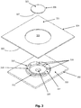
- Fig. 3 depicts some of the basic components of the cutting machine 300, which includes a first component, referred to hereinafter as a base plate 302, a second component referred to hereinafter an outer plate 304, and a third component referred to hereinafter as an inner plate 306.
- the base plate 302 has a die projection 310 projecting from a front surface 315 of the base plate 302.
- the die projection 310 has a shape designed to produce the required features of the desired cut foam product 100.
- the die projection 310 comprises a ring shaped projection 312 having an upper surface 314 with a series of radial channels 316 and a semi-circumferential groove 318.
- the base plate 302 also has a central hole 320, passing through the base plate 302.
- the outer plate 304 has a front cutting surface 321, an opposing back surface 322 and a circular aperture 325 with a slightly larger diameter than the die projection 310.
- the aperture 325 determines the external size and shape of the desired cut foam product 100 and can be any shape or size desired.
- the inner plate 306 has a front surface 323 and an opposing back surface 327 and has a slightly smaller diameter than the internal diameter of the ring-shaped die projection 310.
- the inner plate 306 can be any shape or size in order to produce apertures in the cut foam product 100 having specific shapes and sizes. Multiple inner plates 306 can also be used to produce multiple apertures in the cut foam product 100.
- the cutting machine 300 is depicted in Fig. 4 , in a blank loading configuration.
- the cutting machine 300 has a blank holder 324 incorporating the outer plate 304.
- the base plate 302 of the cutting machine 300 is mounted for sliding movement relative to the blank holder 324, with the base plate 302 remaining parallel to the outer plate 304 and moving normal to the front surface 315 of the base plate 302 and the front surface 321 of the outer plate 304.
- the die projection 310 is axially aligned with the circular aperture 325 and the base plate 302 is axially movable between a distal position, in which the base plate 302 is spaced away from the outer plate 304 such that a tailored foam blank 200 can be loaded between the outer plate 304 and the base plate 302, and a proximal position, in which the base plate 302 compresses the tailored foam blank 200 between the base plate 302 and the outer plate 304.
- a custom shaped bracket is provided on the rear surface of the outer plate 304 within the blank holder 324.
- the custom bracket is shaped to receive the tailored blank 200 and to hold it in correct alignment with the aperture 325 against the inside surface of the outer plate 304.
- the inner plate 306 is attached, or integral with, a stem 326.
- the inner plate 306 and stem 326 are electromagnetically held by an electromagnetic carrier 328, which is axially movable between a retracted position, shown in Fig. 4 in which the electromagnetic carrier 328, inner plate 306 and stem 326 are spaced away from the blank holder 324, and a deployment position, in which the electromagnetic carrier 328 is adjacent to the plane defined by the front surface 321 of the outer plate 304.
- the electromagnetic carrier 328 locates the inner plate 306 in the circular aperture 325, such that the front surface 323 of the inner plate 306 is coplanar with the front surface 321 of the outer plate 304 and the stem 326 passes through the central hole 320 in the base plate 302.
- FIG. 5 This position is depicted in Fig. 5 and forms a peripheral aperture 329 between the inner plate 306 and outer plate 304, which extends around the entire lateral periphery of the inner plate 306.
- a releasable locking mechanism such as a bolt or clamp, is provided in the blank holder 324 to engage the stem 326 and lock the stem 326 and inner plate 306 in a deployed position.
- Fig. 5 shows the inner plate 306 and stem 326 in the deployed position, once the electromagnetic carrier 328 has been demagnetised and returned to the retracted position.
- the cutting blade 330 is depicted in Figs. 4 and 5 and is typically a smooth-edge ground bevel blade.
- the cutting blade 330 and the blank holder 324 are movable one relative to the other such that the cutting blade 330 passes across the front surfaces 321, 323 of the outer plate 304 and inner plate 306.
- the cutting blade 330 is stationary and the blank holder 324 moves relative to the cutting blade 330.
- a moving cutting blade 330 and a stationary blank holder 324 may be employed.
- a compression member 332 is movable between a retracted position, as shown in Fig. 4 in which the compression member 332 is distal to the blank holder 324, and a deployed position, in which the compression member 332 is proximal to the blank holder 324.
- a tailored foam blank 200 is loaded into the custom shaped bracket on the inside of the outer plate 304 and held in place by the bracket.
- the electromagnetic carrier 328 then moves from the retracted position to the deployment position and locates the inner plate 306 and stem 326 in the deployed position.
- the locking mechanism is then used to lock the stem 326 in the blank holder 324 and maintain the inner plate 306 in the deployed position.
- the electromagnet in the carrier 328 is then switched off, releasing the inner plate 306 from the electromagnetic carrier 328 and the electromagnetic carrier 328 is moved back to the retracted position as shown in Fig. 5 .
- the base plate 302 is then moved toward the outer plate 304, compressing the tailored blank 200 between the base plate 302 and the outer plate 304 and inner plate 306, causing the foam to protrude through the peripheral aperture 329 between the outer plate 304 and the inner plate 306. This is shown in cross-section in Fig. 6 .
- the compression member 332 is then moved from the retracted position to the deployed position, pressing into the protruding foam. This is shown in cross-section in Fig. 8 .
- the blank holder 324 is then moved into a cutting alignment position such that the cutting blade 330 is directly adjacent to the front surface 321 of the outer plate 304.
- the blank holder 324 is then moved across the cutting blade 330 in a transverse direction, such that the cutting blade 330 runs across the front surfaces 321, 323 of both the outer plate 304 and the inner plate 306. In doing so, the cutting blade cuts through the protruding foam along the plane defined by the front surfaces 321, 323 of the outer and inner plates 304, 306, resulting in the cut foam product 100 being cut from the tailored foam blank 200.
- Fig. 7 and Fig. 9 depict cross-sections of the foam product 100, 100a that result from cutting the same foam blank in the cutting machine 300, without applying the compression member 332, as depicted in Fig. 6 , and by applying the compression member 332, as depicted in Fig. 8 .
- applying the compression member 332 results in a deeper, more defined groove 112 than not applying the compression member 332. This is because more of the foam material is pressed into the corresponding groove feature 112 of the die projection 310.
- Fig. 10 depicts a cutting machine, in which the die projection 310 is provided with a shim portion 340 that extends laterally, so that the edge of the shim portion 340 approximately aligns with the edge of the peripheral aperture 329.
- the shim portion 340 may be one or more components added to the die projection 310 or may be integrally formed as part of the die projection 310.
- the cutting blade 330 runs continuously in a longitudinal running direction such as indicated by the arrows in Fig. 4 .
- the running direction of the cutting blade 330 and the relative movement of the tailored blank 200 across the cutting blade 330 (or the blade 330 across the blank 200) creates a blade vector V, being the resultant force, acting on the tailored blank 200.
- the force of the blade vector V applied by the cutting blade 330 can have a distorting effect on the tailored foam blank 200.
- the degree of distortion can be a function of the foam material hardness or stiffness. As shown in exaggerated example in Figs.
- the present disclosure provides a cutting machine 300 having a die projection 310 with an asymmetric profile. Relative to the blade vector direction V, the leading edges 350 of the die projection 310 are raised or flared to provide slightly greater protrusion of the foam blank 200 at each leading edge 350. As shown in Fig. 14 , the raised or flared leading edges 350 of the die projection 310 result in the same or corresponding surface profile at the leading edge 108d as the trailing edge 109d of the cut foam product 100d.
- the asymmetric profile balances the effect of the blade vector V and produces a symmetrical and evenly cut foam product 100d.
- the corresponding trailing edges may be relieved relative to the blade vector V to provide the same effect.
- the application of such an asymmetric die projection allows faster cutting strokes thereby improving cutting cycle times and improving the economics of the cutting process.
- the lateral force of the cutting blade 330 can draw extra foam material through the aperture 325 causing the cut foam product to have an undesired variable surface shape and dimension. This can be prevented by having a stop member abutting the protruding foam material, in a direction opposed to the base plate 302 near where the cutting blade exits the foam material.
Landscapes
- Life Sciences & Earth Sciences (AREA)
- Forests & Forestry (AREA)
- Engineering & Computer Science (AREA)
- Mechanical Engineering (AREA)
- Perforating, Stamping-Out Or Severing By Means Other Than Cutting (AREA)
- Details Of Cutting Devices (AREA)
Claims (12)
- Machine de coupe (300) comportant
un support d'ébauche (324) adapté pour recevoir une ébauche de mousse (200), le support d'ébauche (324) comprenant
un premier composant (302) ayant une saillie de matrice (310) formée sur une surface avant (315) du premier composant (302),
un deuxième composant (304) ayant une surface de coupe (321), une surface arrière opposée (322) et une ouverture (325) allant de la surface de coupe (321), via le deuxième composant (304), à la surface arrière (322), l'ouverture (325) correspondant en coupe transversale à la forme externe d'un produit en mousse découpé souhaité (100) et
un troisième composant (306) ayant une surface de coupe plane ininterrompue (323) et une surface arrière opposée (327), le troisième composant (306) pouvant être fixé de manière détachable dans un emplacement déployé dans l'ouverture (325) du deuxième composant (302), de sorte que les surfaces de coupe (321, 323) des deuxième et troisième composants (304, 306) sont coplanaires et forment une ouverture périphérique (329) entre les deuxième et troisième composants (304, 306), l'ouverture (329) s'étendant sur toute la périphérie latérale du troisième composant (306) et
une lame de coupe (330), au moins l'un de la lame de coupe (330) et du support d'ébauche (324) étant monté de manière à se déplacer par rapport à l'autre,
au moins l'un du premier composant (302) et du deuxième composant (304) étant monté pour se déplacer par rapport à l'autre, le troisième composant (306) restant situé dans l'ouverture (325) du deuxième composant (304) pendant ledit mouvement, ledit mouvement allant d'une première configuration dans laquelle les premier et deuxième composants (302, 304) sont en position distale l'un par rapport à l'autre à une seconde configuration dans laquelle les premier et deuxième composants (302, 304) sont en position proximale l'un par rapport à l'autre, avec la surface avant (315) du premier composant (302) opposée à la surface arrière (322) du deuxième composant (304), et dans laquelle la saillie de matrice (310) du premier composant (302) est alignée avec l'ouverture (325) du deuxième composant (304), de sorte à presser le matériau de mousse de l'ébauche de mousse (200) à travers l'ouverture (325) et à le faire avancer au-delà des surfaces de coupe (321, 323), et
la lame de coupe (330) étant adaptée pour passer à travers les surfaces de coupe (321, 323) des deuxième et troisième composants (304, 306) dans la seconde configuration pour couper la mousse qui dépasse de l'ébauche de mousse (200),
caractérisée en ce que la saillie de matrice (310) a des bords surélevés ou évasés sur un bord d'attaque (350) de la saillie de matrice (310) par rapport à un vecteur de lame (V) de la lame de coupe (330). - Machine de coupe (300) selon la revendication 1, comprenant en outre un transporteur (328) adapté pour déployer de manière détachable le troisième composant (306) dans l'emplacement déployé, le transporteur (328) étant rétractable pour permettre à la lame de coupe (330) de traverser toute la surface de coupe (323) du troisième composant (306).
- Machine de coupe (300) selon la revendication 1, dans laquelle le support d'ébauche (324) est monté de sorte à se déplacer par rapport à la lame de coupe (330) qui reste dans une position fixe.
- Machine de coupe (300) selon la revendication 1 ou 2, dans laquelle le premier composant (302) est monté de sorte à se déplacer par rapport aux deuxième et troisième composants (304, 306).
- Machine de coupe (300) selon la revendication 2, dans laquelle le premier composant (302) est une plaque de base, le deuxième composant (304) est une plaque extérieure et le troisième composant (306) est une plaque intérieure et dans laquelle la plaque de base (302) est montée dans le support d'ébauche (324) de sorte à coulisser entre la première configuration et la seconde configuration.
- Machine de coupe (300) selon la revendication 5, dans laquelle le plaque intérieure (306) peut se mouvoir de façon indépendante entre une position rentrée dans laquelle la plaque intérieure (306) est espacée de la plaque extérieure (304) et une position déployée dans laquelle la plaque intérieure (306) est située dans l'ouverture (325) de la plaque extérieure (304).
- Machine de coupe (300) selon la revendication 6, dans laquelle le plaque intérieure (306) a une tige (326) s'étendant de façon sensiblement perpendiculaire à la surface arrière (327) et la plaque de base (302) a un trou central (320) adapté pour recevoir la tige (326) de la plaque intérieure (306).
- Machine de coupe (300) selon la revendication 7, dans laquelle le support d'ébauche (324) comprend en outre un mécanisme de blocage adapté pour bloquer la tige de la plaque intérieure (306) sur le support d'ébauche (324) et retenir la plaque intérieure (306) dans la position déployée.
- Machine de coupe (300) selon l'une quelconque des revendications 6 à 8, dans laquelle ledit transporteur (328) comprend un dispositif de transport électromagnétique adapté pour retenir de façon électromagnétique la plaque intérieure (306), le dispositif de transport électromagnétique (328) étant mobile pour déplacer la plaque intérieure (306) entre les positions rentrée et déployée.
- Machine de coupe (300) selon l'une quelconque des revendications précédentes, dans laquelle le support d'ébauche (324) comprend un dispositif de support d'ébauche adapté pour recevoir et positionner une ébauche de mousse (200) entre le premier composant (302) et le deuxième composant (304), dans un alignement prédéterminé avec l'ouverture (325) du deuxième composant (304).
- Machine de coupe (300) selon l'une quelconque des revendications précédentes, dans laquelle la saillie de matrice (310) a des bords surélevés ou évasés sur un bord d'attaque de la saillie de matrice (310) par rapport à un vecteur de lame (V) de la lame de coupe (330).
- Machine de coupe (300) selon l'une quelconque des revendications précédentes, comprenant en outre un élément de compression (332) adapté pour appliquer une force de compression, perpendiculairement aux surfaces de coupe (321, 323), au matériau de mousse de l'ébauche de mousse (200) saillant à travers l'ouverture périphérique (329) tandis que la lame de coupe (330) passe à travers les surfaces de coupe (321, 323).
Priority Applications (1)
| Application Number | Priority Date | Filing Date | Title |
|---|---|---|---|
| PL16852901T PL3359357T3 (pl) | 2015-10-08 | 2016-10-06 | Maszyna tnąca |
Applications Claiming Priority (2)
| Application Number | Priority Date | Filing Date | Title |
|---|---|---|---|
| AU2015904093A AU2015904093A0 (en) | 2015-10-08 | Cutting machine | |
| PCT/AU2016/050939 WO2017059491A1 (fr) | 2015-10-08 | 2016-10-06 | Machine de coupe |
Publications (3)
| Publication Number | Publication Date |
|---|---|
| EP3359357A1 EP3359357A1 (fr) | 2018-08-15 |
| EP3359357A4 EP3359357A4 (fr) | 2018-11-14 |
| EP3359357B1 true EP3359357B1 (fr) | 2019-11-06 |
Family
ID=58487159
Family Applications (1)
| Application Number | Title | Priority Date | Filing Date |
|---|---|---|---|
| EP16852901.4A Active EP3359357B1 (fr) | 2015-10-08 | 2016-10-06 | Machine de coupe |
Country Status (14)
| Country | Link |
|---|---|
| US (1) | US10759073B2 (fr) |
| EP (1) | EP3359357B1 (fr) |
| JP (1) | JP6785850B2 (fr) |
| KR (1) | KR102562104B1 (fr) |
| CN (1) | CN108136608A (fr) |
| AU (1) | AU2016336031B2 (fr) |
| CA (1) | CA3000849C (fr) |
| DK (1) | DK3359357T3 (fr) |
| ES (1) | ES2769011T3 (fr) |
| MX (1) | MX394031B (fr) |
| MY (1) | MY191280A (fr) |
| NZ (1) | NZ742064A (fr) |
| PL (1) | PL3359357T3 (fr) |
| WO (1) | WO2017059491A1 (fr) |
Family Cites Families (17)
| Publication number | Priority date | Publication date | Assignee | Title |
|---|---|---|---|---|
| US1145654A (en) * | 1914-02-02 | 1915-07-06 | David W Anderson | Method of making convexed or concaved bodies of felt or other flexible substances. |
| US1868932A (en) * | 1928-01-31 | 1932-07-26 | Rubbersan Products Inc | Method and apparatus for forming receptacles from sponge rubber |
| US2404731A (en) * | 1943-11-29 | 1946-07-23 | Ross H Johnson | Making insoles |
| GB874014A (en) * | 1959-02-24 | 1961-08-02 | Cumberland Curled Hair Mfg Com | Improvements relating to the shaping of materials |
| US3311007A (en) * | 1965-09-20 | 1967-03-28 | Vitafoam Ltd | Forming of foamed material articles |
| US3665792A (en) * | 1970-02-20 | 1972-05-30 | James S Bush | Method and aparatus for forming foam material |
| US3695128A (en) * | 1970-09-14 | 1972-10-03 | Califoam Corp Of America | Machine for forming cavities in foam pads and trimming same |
| FR2479073A1 (fr) | 1980-03-25 | 1981-10-02 | Sovra Sa | Procede et dispositif de decoupe en forme de pieces de mousse plastique |
| US6176164B1 (en) * | 1999-08-16 | 2001-01-23 | Robert B. Nylander | Compression cutting process for flexible form and template for use therewith |
| KR100562030B1 (ko) * | 2004-09-03 | 2006-03-22 | 이시헌 | 스펀지의 유연성·탄성을 이용한 요철형상 가공방법 |
| DE102007034136B3 (de) * | 2007-05-02 | 2008-10-16 | Köhler und Krafft GmbH & Co. KG | Verfahren zum Herstellen eines formgeschnittenen Gegenstandes aus Schaumstoff |
| CA2941584C (fr) * | 2008-09-12 | 2019-03-05 | Resmed Ltd | Procede et appareil pour structure d'interface a base de mousse |
| WO2010028426A1 (fr) * | 2008-09-12 | 2010-03-18 | Precision Foam Technologies Pty Limited | Appareil et procédé de coupe de mousse |
| JP5103347B2 (ja) * | 2008-10-02 | 2012-12-19 | 北陸化成株式会社 | 発泡樹脂製パッド成形装置 |
| FR2936685B1 (fr) * | 2008-10-03 | 2010-10-22 | Matthieu Frenet | Procede de production en grande serie de pieces rapportees de chaussure fonctionnelles et pieces rapportees de chaussure polyvalentes produites avec ledit procede. |
| CN201950705U (zh) * | 2010-12-17 | 2011-08-31 | 常州市新罗特数控机械有限公司 | Cnc四轴全自动泡沫免模成型机 |
| TW201505799A (zh) * | 2013-03-15 | 2015-02-16 | Resmed Ltd | 生產面罩墊之方法及設備 |
-
2016
- 2016-10-06 EP EP16852901.4A patent/EP3359357B1/fr active Active
- 2016-10-06 CN CN201680058724.9A patent/CN108136608A/zh active Pending
- 2016-10-06 PL PL16852901T patent/PL3359357T3/pl unknown
- 2016-10-06 ES ES16852901T patent/ES2769011T3/es active Active
- 2016-10-06 NZ NZ742064A patent/NZ742064A/en unknown
- 2016-10-06 MX MX2018004222A patent/MX394031B/es unknown
- 2016-10-06 US US15/765,989 patent/US10759073B2/en active Active
- 2016-10-06 MY MYPI2018701368A patent/MY191280A/en unknown
- 2016-10-06 JP JP2018518496A patent/JP6785850B2/ja active Active
- 2016-10-06 DK DK16852901.4T patent/DK3359357T3/da active
- 2016-10-06 KR KR1020187012334A patent/KR102562104B1/ko active Active
- 2016-10-06 AU AU2016336031A patent/AU2016336031B2/en active Active
- 2016-10-06 WO PCT/AU2016/050939 patent/WO2017059491A1/fr not_active Ceased
- 2016-10-06 CA CA3000849A patent/CA3000849C/fr active Active
Non-Patent Citations (1)
| Title |
|---|
| None * |
Also Published As
| Publication number | Publication date |
|---|---|
| AU2016336031B2 (en) | 2018-05-17 |
| EP3359357A4 (fr) | 2018-11-14 |
| NZ742064A (en) | 2019-07-26 |
| MX394031B (es) | 2025-03-24 |
| US20180281217A1 (en) | 2018-10-04 |
| JP6785850B2 (ja) | 2020-11-18 |
| JP2018534160A (ja) | 2018-11-22 |
| ES2769011T3 (es) | 2020-06-24 |
| CN108136608A (zh) | 2018-06-08 |
| CA3000849A1 (fr) | 2017-04-13 |
| EP3359357A1 (fr) | 2018-08-15 |
| US10759073B2 (en) | 2020-09-01 |
| CA3000849C (fr) | 2023-12-12 |
| MX2018004222A (es) | 2018-08-24 |
| KR102562104B1 (ko) | 2023-08-01 |
| WO2017059491A1 (fr) | 2017-04-13 |
| DK3359357T3 (da) | 2020-02-17 |
| PL3359357T3 (pl) | 2020-11-02 |
| KR20180066122A (ko) | 2018-06-18 |
| AU2016336031A1 (en) | 2018-04-26 |
| MY191280A (en) | 2022-06-13 |
Similar Documents
| Publication | Publication Date | Title |
|---|---|---|
| US9044801B2 (en) | Deep draw manufacturing process | |
| KR102193597B1 (ko) | 버를 가지는 압인되거나 정밀-블랭킹된 부품의 전단 에지의 형상화 장치 및 방법 | |
| JP2014528838A5 (fr) | ||
| JP6566943B2 (ja) | 無段変速機用のプッシュベルト用の横断セグメントを製造する方法及び該方法によって製造される横断セグメント | |
| AU2009291492B2 (en) | Foam cutting apparatus and method | |
| CN106077278B (zh) | 将板形工件的工件部分间的连接筋压力成形的装置和方法 | |
| US20170043495A1 (en) | Three dimensional part rotary die cutting mechanism and method of operating the same | |
| JP2018051627A (ja) | 工作物の製造方法、および本方法を実施するための穴開け処理ツール | |
| EP3359357B1 (fr) | Machine de coupe | |
| JP2016087683A (ja) | プレス成形型 | |
| JP5796526B2 (ja) | 打ち抜き加工装置および打ち抜き加工方法 | |
| JP6760153B2 (ja) | ロータリーダイカッターのダイカットロール | |
| CN106132609B (zh) | 借助高速剪切在金属体中产生通孔的方法 | |
| JP2010058142A (ja) | シャープエッジを備えた筒状金属部品のプレス成形方法 | |
| KR101674764B1 (ko) | 프레스 성형 장치 및 방법 | |
| CN106102947A (zh) | 用于具有边沿槽的冲压件的具有顶出器的模具 | |
| EP3395466A1 (fr) | Appareil et procédé d'estampage à rouleaux | |
| JP2010029918A (ja) | Cvtベルト用エレメントの打抜き加工方法及び打抜き加工用金型 | |
| KR20180136729A (ko) | 가변 그루브 핀이 적용된 펀치를 갖는 코이닝 장치 | |
| KR101825298B1 (ko) | 가변형 채널을 구비하는 연속 전단 변형용 분리형 금형 | |
| JP2017070990A (ja) | 缶製造装置 | |
| KR101704009B1 (ko) | 프레스 금형 홀 형성장치 및 홀 형성방법 | |
| KR101864638B1 (ko) | 금속 성형 장치 | |
| KR101606671B1 (ko) | 가공물의 언더컷 성형장치 |
Legal Events
| Date | Code | Title | Description |
|---|---|---|---|
| STAA | Information on the status of an ep patent application or granted ep patent |
Free format text: STATUS: THE INTERNATIONAL PUBLICATION HAS BEEN MADE |
|
| PUAI | Public reference made under article 153(3) epc to a published international application that has entered the european phase |
Free format text: ORIGINAL CODE: 0009012 |
|
| STAA | Information on the status of an ep patent application or granted ep patent |
Free format text: STATUS: REQUEST FOR EXAMINATION WAS MADE |
|
| 17P | Request for examination filed |
Effective date: 20180503 |
|
| AK | Designated contracting states |
Kind code of ref document: A1 Designated state(s): AL AT BE BG CH CY CZ DE DK EE ES FI FR GB GR HR HU IE IS IT LI LT LU LV MC MK MT NL NO PL PT RO RS SE SI SK SM TR |
|
| AX | Request for extension of the european patent |
Extension state: BA ME |
|
| A4 | Supplementary search report drawn up and despatched |
Effective date: 20181012 |
|
| RIC1 | Information provided on ipc code assigned before grant |
Ipc: B26D 7/04 20060101ALI20181008BHEP Ipc: B26D 1/12 20060101ALI20181008BHEP Ipc: B26D 3/00 20060101ALI20181008BHEP Ipc: B26D 7/02 20060101ALI20181008BHEP Ipc: B26D 3/28 20060101AFI20181008BHEP |
|
| DAV | Request for validation of the european patent (deleted) | ||
| DAX | Request for extension of the european patent (deleted) | ||
| GRAP | Despatch of communication of intention to grant a patent |
Free format text: ORIGINAL CODE: EPIDOSNIGR1 |
|
| STAA | Information on the status of an ep patent application or granted ep patent |
Free format text: STATUS: GRANT OF PATENT IS INTENDED |
|
| INTG | Intention to grant announced |
Effective date: 20190520 |
|
| GRAS | Grant fee paid |
Free format text: ORIGINAL CODE: EPIDOSNIGR3 |
|
| GRAA | (expected) grant |
Free format text: ORIGINAL CODE: 0009210 |
|
| STAA | Information on the status of an ep patent application or granted ep patent |
Free format text: STATUS: THE PATENT HAS BEEN GRANTED |
|
| AK | Designated contracting states |
Kind code of ref document: B1 Designated state(s): AL AT BE BG CH CY CZ DE DK EE ES FI FR GB GR HR HU IE IS IT LI LT LU LV MC MK MT NL NO PL PT RO RS SE SI SK SM TR |
|
| REG | Reference to a national code |
Ref country code: GB Ref legal event code: FG4D |
|
| REG | Reference to a national code |
Ref country code: CH Ref legal event code: EP Ref country code: AT Ref legal event code: REF Ref document number: 1198132 Country of ref document: AT Kind code of ref document: T Effective date: 20191115 |
|
| REG | Reference to a national code |
Ref country code: IE Ref legal event code: FG4D |
|
| REG | Reference to a national code |
Ref country code: DE Ref legal event code: R096 Ref document number: 602016024062 Country of ref document: DE |
|
| REG | Reference to a national code |
Ref country code: DK Ref legal event code: T3 Effective date: 20200211 |
|
| REG | Reference to a national code |
Ref country code: SE Ref legal event code: TRGR |
|
| REG | Reference to a national code |
Ref country code: NL Ref legal event code: FP |
|
| REG | Reference to a national code |
Ref country code: NO Ref legal event code: T2 Effective date: 20191106 |
|
| REG | Reference to a national code |
Ref country code: LT Ref legal event code: MG4D |
|
| REG | Reference to a national code |
Ref country code: CH Ref legal event code: NV Representative=s name: RAPISARDI INTELLECTUAL PROPERTY SA, CH |
|
| PG25 | Lapsed in a contracting state [announced via postgrant information from national office to epo] |
Ref country code: BG Free format text: LAPSE BECAUSE OF FAILURE TO SUBMIT A TRANSLATION OF THE DESCRIPTION OR TO PAY THE FEE WITHIN THE PRESCRIBED TIME-LIMIT Effective date: 20200206 Ref country code: FI Free format text: LAPSE BECAUSE OF FAILURE TO SUBMIT A TRANSLATION OF THE DESCRIPTION OR TO PAY THE FEE WITHIN THE PRESCRIBED TIME-LIMIT Effective date: 20191106 Ref country code: LV Free format text: LAPSE BECAUSE OF FAILURE TO SUBMIT A TRANSLATION OF THE DESCRIPTION OR TO PAY THE FEE WITHIN THE PRESCRIBED TIME-LIMIT Effective date: 20191106 Ref country code: PT Free format text: LAPSE BECAUSE OF FAILURE TO SUBMIT A TRANSLATION OF THE DESCRIPTION OR TO PAY THE FEE WITHIN THE PRESCRIBED TIME-LIMIT Effective date: 20200306 Ref country code: GR Free format text: LAPSE BECAUSE OF FAILURE TO SUBMIT A TRANSLATION OF THE DESCRIPTION OR TO PAY THE FEE WITHIN THE PRESCRIBED TIME-LIMIT Effective date: 20200207 Ref country code: LT Free format text: LAPSE BECAUSE OF FAILURE TO SUBMIT A TRANSLATION OF THE DESCRIPTION OR TO PAY THE FEE WITHIN THE PRESCRIBED TIME-LIMIT Effective date: 20191106 |
|
| PG25 | Lapsed in a contracting state [announced via postgrant information from national office to epo] |
Ref country code: IS Free format text: LAPSE BECAUSE OF FAILURE TO SUBMIT A TRANSLATION OF THE DESCRIPTION OR TO PAY THE FEE WITHIN THE PRESCRIBED TIME-LIMIT Effective date: 20200306 Ref country code: HR Free format text: LAPSE BECAUSE OF FAILURE TO SUBMIT A TRANSLATION OF THE DESCRIPTION OR TO PAY THE FEE WITHIN THE PRESCRIBED TIME-LIMIT Effective date: 20191106 Ref country code: RS Free format text: LAPSE BECAUSE OF FAILURE TO SUBMIT A TRANSLATION OF THE DESCRIPTION OR TO PAY THE FEE WITHIN THE PRESCRIBED TIME-LIMIT Effective date: 20191106 |
|
| REG | Reference to a national code |
Ref country code: ES Ref legal event code: FG2A Ref document number: 2769011 Country of ref document: ES Kind code of ref document: T3 Effective date: 20200624 |
|
| PG25 | Lapsed in a contracting state [announced via postgrant information from national office to epo] |
Ref country code: AL Free format text: LAPSE BECAUSE OF FAILURE TO SUBMIT A TRANSLATION OF THE DESCRIPTION OR TO PAY THE FEE WITHIN THE PRESCRIBED TIME-LIMIT Effective date: 20191106 |
|
| PG25 | Lapsed in a contracting state [announced via postgrant information from national office to epo] |
Ref country code: EE Free format text: LAPSE BECAUSE OF FAILURE TO SUBMIT A TRANSLATION OF THE DESCRIPTION OR TO PAY THE FEE WITHIN THE PRESCRIBED TIME-LIMIT Effective date: 20191106 Ref country code: RO Free format text: LAPSE BECAUSE OF FAILURE TO SUBMIT A TRANSLATION OF THE DESCRIPTION OR TO PAY THE FEE WITHIN THE PRESCRIBED TIME-LIMIT Effective date: 20191106 Ref country code: CZ Free format text: LAPSE BECAUSE OF FAILURE TO SUBMIT A TRANSLATION OF THE DESCRIPTION OR TO PAY THE FEE WITHIN THE PRESCRIBED TIME-LIMIT Effective date: 20191106 |
|
| REG | Reference to a national code |
Ref country code: DE Ref legal event code: R097 Ref document number: 602016024062 Country of ref document: DE |
|
| PG25 | Lapsed in a contracting state [announced via postgrant information from national office to epo] |
Ref country code: SM Free format text: LAPSE BECAUSE OF FAILURE TO SUBMIT A TRANSLATION OF THE DESCRIPTION OR TO PAY THE FEE WITHIN THE PRESCRIBED TIME-LIMIT Effective date: 20191106 Ref country code: SK Free format text: LAPSE BECAUSE OF FAILURE TO SUBMIT A TRANSLATION OF THE DESCRIPTION OR TO PAY THE FEE WITHIN THE PRESCRIBED TIME-LIMIT Effective date: 20191106 |
|
| PLBE | No opposition filed within time limit |
Free format text: ORIGINAL CODE: 0009261 |
|
| STAA | Information on the status of an ep patent application or granted ep patent |
Free format text: STATUS: NO OPPOSITION FILED WITHIN TIME LIMIT |
|
| 26N | No opposition filed |
Effective date: 20200807 |
|
| PG25 | Lapsed in a contracting state [announced via postgrant information from national office to epo] |
Ref country code: SI Free format text: LAPSE BECAUSE OF FAILURE TO SUBMIT A TRANSLATION OF THE DESCRIPTION OR TO PAY THE FEE WITHIN THE PRESCRIBED TIME-LIMIT Effective date: 20191106 |
|
| PG25 | Lapsed in a contracting state [announced via postgrant information from national office to epo] |
Ref country code: MC Free format text: LAPSE BECAUSE OF FAILURE TO SUBMIT A TRANSLATION OF THE DESCRIPTION OR TO PAY THE FEE WITHIN THE PRESCRIBED TIME-LIMIT Effective date: 20191106 Ref country code: LU Free format text: LAPSE BECAUSE OF NON-PAYMENT OF DUE FEES Effective date: 20201006 |
|
| REG | Reference to a national code |
Ref country code: AT Ref legal event code: UEP Ref document number: 1198132 Country of ref document: AT Kind code of ref document: T Effective date: 20191106 |
|
| PG25 | Lapsed in a contracting state [announced via postgrant information from national office to epo] |
Ref country code: TR Free format text: LAPSE BECAUSE OF FAILURE TO SUBMIT A TRANSLATION OF THE DESCRIPTION OR TO PAY THE FEE WITHIN THE PRESCRIBED TIME-LIMIT Effective date: 20191106 Ref country code: MT Free format text: LAPSE BECAUSE OF FAILURE TO SUBMIT A TRANSLATION OF THE DESCRIPTION OR TO PAY THE FEE WITHIN THE PRESCRIBED TIME-LIMIT Effective date: 20191106 Ref country code: CY Free format text: LAPSE BECAUSE OF FAILURE TO SUBMIT A TRANSLATION OF THE DESCRIPTION OR TO PAY THE FEE WITHIN THE PRESCRIBED TIME-LIMIT Effective date: 20191106 |
|
| PG25 | Lapsed in a contracting state [announced via postgrant information from national office to epo] |
Ref country code: MK Free format text: LAPSE BECAUSE OF FAILURE TO SUBMIT A TRANSLATION OF THE DESCRIPTION OR TO PAY THE FEE WITHIN THE PRESCRIBED TIME-LIMIT Effective date: 20191106 |
|
| REG | Reference to a national code |
Ref country code: CH Ref legal event code: U11 Free format text: ST27 STATUS EVENT CODE: U-0-0-U10-U11 (AS PROVIDED BY THE NATIONAL OFFICE) Effective date: 20251101 |
|
| PGFP | Annual fee paid to national office [announced via postgrant information from national office to epo] |
Ref country code: NL Payment date: 20251021 Year of fee payment: 10 |
|
| PGFP | Annual fee paid to national office [announced via postgrant information from national office to epo] |
Ref country code: DE Payment date: 20251021 Year of fee payment: 10 |
|
| PGFP | Annual fee paid to national office [announced via postgrant information from national office to epo] |
Ref country code: GB Payment date: 20251022 Year of fee payment: 10 |
|
| PGFP | Annual fee paid to national office [announced via postgrant information from national office to epo] |
Ref country code: NO Payment date: 20251024 Year of fee payment: 10 |
|
| PGFP | Annual fee paid to national office [announced via postgrant information from national office to epo] |
Ref country code: AT Payment date: 20251022 Year of fee payment: 10 |
|
| PGFP | Annual fee paid to national office [announced via postgrant information from national office to epo] |
Ref country code: DK Payment date: 20251027 Year of fee payment: 10 Ref country code: IT Payment date: 20251024 Year of fee payment: 10 |
|
| PGFP | Annual fee paid to national office [announced via postgrant information from national office to epo] |
Ref country code: FR Payment date: 20251030 Year of fee payment: 10 |
|
| PGFP | Annual fee paid to national office [announced via postgrant information from national office to epo] |
Ref country code: BE Payment date: 20251021 Year of fee payment: 10 |
|
| PGFP | Annual fee paid to national office [announced via postgrant information from national office to epo] |
Ref country code: CH Payment date: 20251101 Year of fee payment: 10 Ref country code: SE Payment date: 20251021 Year of fee payment: 10 |
|
| PGFP | Annual fee paid to national office [announced via postgrant information from national office to epo] |
Ref country code: IE Payment date: 20251024 Year of fee payment: 10 |
|
| PGFP | Annual fee paid to national office [announced via postgrant information from national office to epo] |
Ref country code: ES Payment date: 20251216 Year of fee payment: 10 |
|
| PGFP | Annual fee paid to national office [announced via postgrant information from national office to epo] |
Ref country code: PL Payment date: 20260206 Year of fee payment: 10 |