EP3359421B1 - Elektrooptischer spiegel mit benutzerseitig verstellbarem dimmen mit visuellem feedback - Google Patents
Elektrooptischer spiegel mit benutzerseitig verstellbarem dimmen mit visuellem feedback Download PDFInfo
- Publication number
- EP3359421B1 EP3359421B1 EP16854376.7A EP16854376A EP3359421B1 EP 3359421 B1 EP3359421 B1 EP 3359421B1 EP 16854376 A EP16854376 A EP 16854376A EP 3359421 B1 EP3359421 B1 EP 3359421B1
- Authority
- EP
- European Patent Office
- Prior art keywords
- images
- display
- vehicle
- electro
- user
- Prior art date
- Legal status (The legal status is an assumption and is not a legal conclusion. Google has not performed a legal analysis and makes no representation as to the accuracy of the status listed.)
- Active
Links
Images


Classifications
-
- G—PHYSICS
- G09—EDUCATION; CRYPTOGRAPHY; DISPLAY; ADVERTISING; SEALS
- G09G—ARRANGEMENTS OR CIRCUITS FOR CONTROL OF INDICATING DEVICES USING STATIC MEANS TO PRESENT VARIABLE INFORMATION
- G09G3/00—Control arrangements or circuits, of interest only in connection with visual indicators other than cathode-ray tubes
- G09G3/20—Control arrangements or circuits, of interest only in connection with visual indicators other than cathode-ray tubes for presentation of an assembly of a number of characters, e.g. a page, by composing the assembly by combination of individual elements arranged in a matrix no fixed position being assigned to or needed to be assigned to the individual characters or partial characters
- G09G3/34—Control arrangements or circuits, of interest only in connection with visual indicators other than cathode-ray tubes for presentation of an assembly of a number of characters, e.g. a page, by composing the assembly by combination of individual elements arranged in a matrix no fixed position being assigned to or needed to be assigned to the individual characters or partial characters by control of light from an independent source
- G09G3/3406—Control of illumination source
-
- B—PERFORMING OPERATIONS; TRANSPORTING
- B60—VEHICLES IN GENERAL
- B60R—VEHICLES, VEHICLE FITTINGS, OR VEHICLE PARTS, NOT OTHERWISE PROVIDED FOR
- B60R1/00—Optical viewing arrangements; Real-time viewing arrangements for drivers or passengers using optical image capturing systems, e.g. cameras or video systems specially adapted for use in or on vehicles
- B60R1/02—Rear-view mirror arrangements
- B60R1/08—Rear-view mirror arrangements involving special optical features, e.g. avoiding blind spots, e.g. convex mirrors; Side-by-side associations of rear-view and other mirrors
- B60R1/083—Anti-glare mirrors, e.g. "day-night" mirrors
- B60R1/088—Anti-glare mirrors, e.g. "day-night" mirrors using a cell of electrically changeable optical characteristic, e.g. liquid-crystal or electrochromic mirrors
-
- G—PHYSICS
- G02—OPTICS
- G02F—OPTICAL DEVICES OR ARRANGEMENTS FOR THE CONTROL OF LIGHT BY MODIFICATION OF THE OPTICAL PROPERTIES OF THE MEDIA OF THE ELEMENTS INVOLVED THEREIN; NON-LINEAR OPTICS; FREQUENCY-CHANGING OF LIGHT; OPTICAL LOGIC ELEMENTS; OPTICAL ANALOGUE/DIGITAL CONVERTERS
- G02F1/00—Devices or arrangements for the control of the intensity, colour, phase, polarisation or direction of light arriving from an independent light source, e.g. switching, gating or modulating; Non-linear optics
- G02F1/01—Devices or arrangements for the control of the intensity, colour, phase, polarisation or direction of light arriving from an independent light source, e.g. switching, gating or modulating; Non-linear optics for the control of the intensity, phase, polarisation or colour
- G02F1/15—Devices or arrangements for the control of the intensity, colour, phase, polarisation or direction of light arriving from an independent light source, e.g. switching, gating or modulating; Non-linear optics for the control of the intensity, phase, polarisation or colour based on an electrochromic effect
- G02F1/153—Constructional details
- G02F1/157—Structural association of cells with optical devices, e.g. reflectors or illuminating devices
-
- G—PHYSICS
- G09—EDUCATION; CRYPTOGRAPHY; DISPLAY; ADVERTISING; SEALS
- G09G—ARRANGEMENTS OR CIRCUITS FOR CONTROL OF INDICATING DEVICES USING STATIC MEANS TO PRESENT VARIABLE INFORMATION
- G09G3/00—Control arrangements or circuits, of interest only in connection with visual indicators other than cathode-ray tubes
- G09G3/20—Control arrangements or circuits, of interest only in connection with visual indicators other than cathode-ray tubes for presentation of an assembly of a number of characters, e.g. a page, by composing the assembly by combination of individual elements arranged in a matrix no fixed position being assigned to or needed to be assigned to the individual characters or partial characters
- G09G3/34—Control arrangements or circuits, of interest only in connection with visual indicators other than cathode-ray tubes for presentation of an assembly of a number of characters, e.g. a page, by composing the assembly by combination of individual elements arranged in a matrix no fixed position being assigned to or needed to be assigned to the individual characters or partial characters by control of light from an independent source
- G09G3/38—Control arrangements or circuits, of interest only in connection with visual indicators other than cathode-ray tubes for presentation of an assembly of a number of characters, e.g. a page, by composing the assembly by combination of individual elements arranged in a matrix no fixed position being assigned to or needed to be assigned to the individual characters or partial characters by control of light from an independent source using electrochromic devices
-
- B—PERFORMING OPERATIONS; TRANSPORTING
- B60—VEHICLES IN GENERAL
- B60R—VEHICLES, VEHICLE FITTINGS, OR VEHICLE PARTS, NOT OTHERWISE PROVIDED FOR
- B60R1/00—Optical viewing arrangements; Real-time viewing arrangements for drivers or passengers using optical image capturing systems, e.g. cameras or video systems specially adapted for use in or on vehicles
- B60R1/12—Mirror assemblies combined with other articles, e.g. clocks
- B60R2001/1215—Mirror assemblies combined with other articles, e.g. clocks with information displays
-
- B—PERFORMING OPERATIONS; TRANSPORTING
- B60—VEHICLES IN GENERAL
- B60R—VEHICLES, VEHICLE FITTINGS, OR VEHICLE PARTS, NOT OTHERWISE PROVIDED FOR
- B60R1/00—Optical viewing arrangements; Real-time viewing arrangements for drivers or passengers using optical image capturing systems, e.g. cameras or video systems specially adapted for use in or on vehicles
- B60R1/12—Mirror assemblies combined with other articles, e.g. clocks
- B60R2001/1223—Mirror assemblies combined with other articles, e.g. clocks with sensors or transducers
-
- G—PHYSICS
- G09—EDUCATION; CRYPTOGRAPHY; DISPLAY; ADVERTISING; SEALS
- G09G—ARRANGEMENTS OR CIRCUITS FOR CONTROL OF INDICATING DEVICES USING STATIC MEANS TO PRESENT VARIABLE INFORMATION
- G09G2320/00—Control of display operating conditions
- G09G2320/06—Adjustment of display parameters
- G09G2320/0626—Adjustment of display parameters for control of overall brightness
-
- G—PHYSICS
- G09—EDUCATION; CRYPTOGRAPHY; DISPLAY; ADVERTISING; SEALS
- G09G—ARRANGEMENTS OR CIRCUITS FOR CONTROL OF INDICATING DEVICES USING STATIC MEANS TO PRESENT VARIABLE INFORMATION
- G09G2354/00—Aspects of interface with display user
-
- G—PHYSICS
- G09—EDUCATION; CRYPTOGRAPHY; DISPLAY; ADVERTISING; SEALS
- G09G—ARRANGEMENTS OR CIRCUITS FOR CONTROL OF INDICATING DEVICES USING STATIC MEANS TO PRESENT VARIABLE INFORMATION
- G09G2360/00—Aspects of the architecture of display systems
- G09G2360/14—Detecting light within display terminals, e.g. using a single or a plurality of photosensors
- G09G2360/144—Detecting light within display terminals, e.g. using a single or a plurality of photosensors the light being ambient light
-
- G—PHYSICS
- G09—EDUCATION; CRYPTOGRAPHY; DISPLAY; ADVERTISING; SEALS
- G09G—ARRANGEMENTS OR CIRCUITS FOR CONTROL OF INDICATING DEVICES USING STATIC MEANS TO PRESENT VARIABLE INFORMATION
- G09G2380/00—Specific applications
- G09G2380/10—Automotive applications
Definitions
- the present invention generally relates to an electro-optic mirror for a vehicle and, more particularly, an electro-optic mirror for a vehicle having a user input for adjusting dimming of the electro-optic element.
- US 2014/022390 A1 discloses an interior rearview mirror assembly for a vehicle including a mirror reflective element and a video display device operable to display video information that is viewable by a driver of the vehicle through said mirror reflective element and at a display region of said mirror reflective element.
- the rearview mirror assembly comprises an electro-optic mirror element that reflects images from the rear of the vehicle, wherein the reflected images may be dimmed in response to a detection of glare from headlights of a trailing vehicle; a user input for receiving user adjustment of an extent to which the electro-optic mirror element is to be dimmed to reduce glare light from headlights of trailing vehicles; a processor coupled to the electro-optic mirror element and the user input for adjusting the extent to which the electro-optic mirror element is dimmed in response to user adjustment via the user input; and a display positioned behind the electro-optic mirror element for displaying images of a rearward scene to a driver of the vehicle.
- the processor causes simulated images of vehicle headlights to be displayed on the display where the simulated images are dimmed to a level selected by the user.
- relational terms such as first and second, top and bottom, and the like, are used solely to distinguish one entity or action from another entity or action, without necessarily requiring or implying any actual such relationship or order between such entities or actions.
- the terms "comprises,” “comprising,” or any other variation thereof are intended to cover a non-exclusive inclusion, such that a process, method, article, or apparatus that comprises a list of elements does not include only those elements, but may include other elements not expressly listed or inherent to such process, method, article, or apparatus.
- Rearview mirror assemblies are known for use in vehicles that include an electro-optic element, such as an electrochromic mirror element, that automatically selectively attenuates light that reflects off the mirror in order to reduce excessive glare that may be caused by, for example, bright headlamps of a trailing vehicle at nighttime. Headlamps from a trailing vehicle generally only cause excessive glare during nighttime or dark conditions in which the driver's eyes adapt to the dark ambient light levels.
- such known mirror assemblies typically include an ambient light sensor so that when the ambient light is bright, the auto-dimming feature is disabled, and when the ambient light is dark, auto-dimming is enabled.
- electrochromic mirrors also utilize a glare light sensor for sensing glare light that is impinging upon the mirror surface and hence reflected towards the eyes of the driver. Electrochromic mirror elements change color in response to an applied voltage level so as to darken and thereby attenuate impinging light prior to striking a reflective layer and after it is reflected from the reflecting layer towards the eyes of the driver. Thus, the electrochromic mirror "dims" when excessive glare with light levels is detected by the glare light sensor, which faces rearward from the mirror assembly. Electrochromic mirror elements dim sufficiently to change the perceived brightness of the headlamps such that the driver may still notice the headlamps and yet not be distracted by an overly bright reflected image of the headlamps.
- Prior electrochromic mirror assemblies have been constructed that include a user input so as to allow a user to adjust the extent to which the electrochromic mirror element dims in response to a given glare light level.
- a user input has led to customer confusion as a result of the customers adjusting the extent of dimming when actual glare light was inadequate at the time of adjustment, and thus customers either over or under adjust the electrochromic mirror element dimming capacity.
- electrochromic mirror elements have typically not included the ability for a user to adjust the extent of dimming. Further, electrochromic mirror elements do not dim immediately. Accordingly, even when glare light is present at the time of adjustment, a user would not get immediate feedback as to the extent to which the dimming level has been adjusted.
- the embodiments described herein address the issues involved with providing user input for adjusting the extent of mirror dimming by providing a mechanism for feedback to the user so that the user may see how much of an adjustment the user is making at the time of adjustment. More specifically, as shown in Figs.
- a rearview assembly 10 that includes a glare light sensor 45 for detecting glare light from a rearward direction, an electro-optic mirror element 20 that reflects images from the rear of the vehicle, where the reflected images may be dimmed in response to a detection of glare from headlights of a trailing vehicle, a display 30 positioned behind the electro-optic mirror element 20 for displaying images of a rearward scene to a driver of the vehicle, a user input 50 for receiving user adjustment of an extent to which the electro-optic mirror element 20 is to be dimmed to reduce glare from headlights of trailing vehicles, and a processor 25 in communication with electro-optic mirror element 20, user input 50, glare light sensor 45, and display 30 for adjusting the extent to which electro-optic mirror element 20 is dimmed in response to user adjustment via user input 50.
- processor 25 When user adjustment is made via user input 50, processor 25 causes simulated images 100 of vehicle headlights to be displayed on display 30 where the simulated images 100 are dimmed to a level selected by the user.
- Fig. 1B shows a simulated image 100 in which the headlamps are dimmer relative to the headlamps in the simulated image 100 shown in Fig. 1A .
- visual feedback may be provided to the user at the time at which the adjustments are made. Accordingly, the user may make a more informed adjustment of the dimming level of the electrochromic mirror element 20 while viewing this visual feedback. Further, the visual feedback may be immediate insofar as it is provided by the display 30 rather than by actually dimming the electro-optic element 20.
- User input 50 may take any form including pushbuttons or slider switches, or can be part of a touch screen provided on the surface of the mirror element 20.
- Rearview mirror assembly 10 may further include an ambient light sensor 40 for sensing an ambient light level.
- Processor 25 may receive this ambient light level from sensor 40 and select simulated images to display in response to the ambient light level. This allows the simulated image to have a brightness that produces the same relative level of glare as would be experienced at night. In other words, the brighter the ambient light level, the brighter the simulated image 100.
- rearview mirror assembly 10 may further include a housing 15 in which all the previously described components are housed, as well as a mirror mount 17 for mounting mirror assembly 10 to the windshield or headliner of the vehicle.
- rearview mirror assembly 10 may further include an electro-optic drive circuit 22 that provides a voltage level to the electro-optic mirror element 20 as commanded by processor 25.
- a display driver 32 may be provided for causing selected images, including simulated images 100 to be displayed on display 30 as commanded by processor 25.
- a camera interface 60 may also be provided for receiving images or a video stream from a camera or multiple cameras mounted to the vehicle.
- Rearview mirror assemblies are also known that include a display for displaying images captured by a camera at the rear of the vehicle to assist in backing up the vehicle. Such rearview mirror assemblies have also been known to include electrochromic mirror elements positioned in front of these displays. Examples of mirror assemblies with a reverse camera display are disclosed in U.S. Patent No. 8,339,526 and U.S. Patent Application Publication No. US 2009/0096937 A1 .
- Simulated images 100 may be still images, video images, or animation images where the simulated images show objects (such as headlamps) in various states of brightness so as to simulate the effect of dimming of the mirror element on the reflections of the object.
- objects such as headlamps
- a single simulated image or video stream may be provided where the display brightness is increased or decreased to correspond to the simulated adjustment of the mirror dimming level.
- Such simulated images 100 may be stored in the internal memory of processor 25 or in external memory. By displaying such simulated images 100, a user may make adjustments via user input 50 and view the effect of the adjustments by looking at the simulated images 100 prior to committing to the change.
- the electro-optic element 20 is not dimmed during adjustment, but only after the user commits to the change in the adjustment and when excessive glare light is detected.
- the processor 25 determines whether the detected glare light exceeds a threshold, and dims the electro-optic mirror element 20 to the level previously selected by the user.
- the ability to adjust the extent of dimming may be conditioned upon certain conditions. For example, the ability to adjust the extent of dimming may be disabled upon detection that the vehicle is moving or shifted out of park.
- Electro-optic mirror element 20 may be configured to include any of the partially reflective, partially transmissive (“transflective") coatings disclosed in U.S. Patent No. 6,700,692 . Such a coating may be transflective and cover the entire rear surface of mirror element 20 or may be highly reflective and substantially non-transmissive in some areas of mirror element 20 while being partially reflective and partially transmissive only in the area in front of display 30 (if display 30 is smaller than the viewing area of mirror element 20).
- Electro-optic mirror element 20 may be an electrochromic mirror element. Examples of electrochromic mirror elements are disclosed in U.S. Patent No. 6,700,692 .
- the electrochromic mirror element may have an electrochromic component that is a single-layer component, single-phase component, multi-layer component, or multi-phase component, as described in U.S. Patent Nos. 5,928,572 ; 5,998,617 ; 6,020,987 ; 6,037,471 ; 6,141,137 ; 6,241,916 ; 6,193,912 ; 6,249,369 ; 6,137,620 ; and 6,519,072 ; and International Patent Application Serial Nos.
- PCT/US98/05570 entitled "ELECTROCHROMIC POLYMERIC SOLID FILMS, MANUFACTURING ELECTROCHROMIC DEVICES USING SUCH SOLID FILMS, AND PROCESSES FOR MAKING SUCH SOLID FILMS AND DEVICES;”
- PCT/EP98/03862 entitled “ELECTROCHROMIC POLYMER SYSTEM;”
- PCT/US98/05570 entitled "ELECTROCHROMIC POLYMERIC SOLID FILMS, MANUFACTURING ELECTROCHROMIC DEVICES USING SUCH SOLID FILMS, AND PROCESSES FOR MAKING SUCH SOLID FILMS AND DEVICES.”
- display 30 is shown to only be sized for showing a rear camera display to assist with vehicle back-up in Figs. 1A and 1B
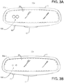
- the display may span substantially the entire area of a viewing surface of the rearview assembly and function as a full display 30a as shown in Figs. 3A and 3B .
- Examples of full display mirror assemblies are disclosed in U.S. Patent Application Publication Nos. US 2015/0277203 A1 and US 2015/0266427 A1 .
- Full display 30a is typically used during both forward and reverse operation of the vehicle to display the rearward images. In a rearview assembly 10a with a full display 30a, the rearward image seen by the driver is the image shown by display 30a rather than a reflected image.
- a reduction in glare light may be achieved by dimming an electro-optic element 20 positioned in front of display 30a, and/or by dimming the brightness of the images shown by display 30a.
- the dimming is carried out in the same manner as set forth above with the back-up assist display 30.
- the user input 50 receives user adjustment of an extent to which the displayed images are to be dimmed to reduce glare light from headlights of trailing vehicles, and the processor 25 adjusts the extent to which the displayed images are dimmed in response to user adjustment via user input 50.
- processor 25 causes simulated images of vehicle headlights to be displayed where the simulated images are dimmed to a brightness level selected by the user.
- the brightness of the simulated images may be adjusted in response to the ambient light level sensed by ambient light sensor 40.
- the glare light level may subsequently be sensed using glare light sensor 45 or the images obtained from the rear camera.
- processor 25 determines whether the detected glare light exceeds a threshold, and dims the displayed images of the rearward scene to the brightness level previously selected by the user.
- a rearview device having a full display 30a may be manually or automatically toggled between a display mode where the full display 30a provides the rearward image and a mirror mode where the mirror element provides the rearward image by reflection.
Landscapes
- Engineering & Computer Science (AREA)
- Physics & Mathematics (AREA)
- General Physics & Mathematics (AREA)
- Computer Hardware Design (AREA)
- Theoretical Computer Science (AREA)
- Nonlinear Science (AREA)
- Optics & Photonics (AREA)
- Chemical & Material Sciences (AREA)
- Crystallography & Structural Chemistry (AREA)
- Multimedia (AREA)
- Mechanical Engineering (AREA)
- Electrochromic Elements, Electrophoresis, Or Variable Reflection Or Absorption Elements (AREA)
- Rear-View Mirror Devices That Are Mounted On The Exterior Of The Vehicle (AREA)
- Optical Elements Other Than Lenses (AREA)
Claims (11)
- Eine Rückspiegelanordnung (10; 10a) für ein Fahrzeug, wobei die Rückspiegelanordnung (10; 10a) Folgendes umfasst:ein elektrooptisches Spiegelelement (20), das Bilder von hinter dem Fahrzeug reflektiert, wobei die reflektierten Bilder als Reaktion auf eine Erfassung von Blendlicht von Scheinwerfern eines nachfolgenden Fahrzeuges gedimmt werden können;eine Anzeige (30; 30a), die hinter dem elektrooptischen Spiegelelement (20) positioniert ist, um einem Fahrer des Fahrzeugs Bilder einer rückwärtigen Szene anzuzeigen;einen Benutzereingang (50) zum Empfangen einer Benutzereinstellung eines Ausmaßes, in dem die angezeigten Bilder gedimmt werden sollen, um das Blendlicht von Scheinwerfern nachfolgender Fahrzeuge zu reduzieren; undeinen Prozessor (25), der gekoppelt ist mit dem elektrooptischen Spiegelelement (20), dem Benutzereingang (50) und der Anzeige (30; 30a), um das Ausmaß einzustellen, in dem die angezeigten Bilder als Reaktion auf eine Benutzereinstellung über den Benutzereingang (50) gedimmt werden, indem das elektrooptische Spiegelelement (20) gedimmt und/oder die Helligkeit der von der Anzeige (30; 30a) angezeigten Bilder gedimmt wird, wobei, wenn die Benutzereinstellung über den Benutzereingang (50) vorgenommen wird, der Prozessor (25) bewirkt, dass simulierte Bilder (100) von Fahrzeugscheinwerfern an der Stelle angezeigt werden, wo die simulierten Bilder (100) auf eine vom Benutzer ausgewählte Helligkeitsstufe gedimmt werden.
- Die Rückspiegelanordnung (10; 10a) nach Anspruch 1, die ferner einen Umgebungslichtsensor (40) zum Erfassen eines Umgebungslichtniveaus umfasst, wobei der Prozessor (25) mit dem Umgebungslichtsensor (40) gekoppelt ist und simulierte Bilder auswählt, die in Antwort auf den vom Umgebungslichtsensor (40) erfassten Umgebungslichtwert angezeigt werden.
- Die Rückspiegelanordnung (10; 10a) nach Anspruch 2, wobei der Prozessor (25) bei zunehmender Umgebungshelligkeit simulierte Bilder (100) mit zunehmender Helligkeit auswählt.
- Die Rückspiegelanordnung (10; 10a) nach irgendeinem der Ansprüche 1 - 3, wobei, wenn das Fahrzeug in Betrieb ist, der Prozessor (25) bestimmt, ob das erfasste Blendlicht einen Schwellenwert überschreitet, und die reflektierten Bilder der Rückwärtsszene auf die zuvor vom Benutzer ausgewählte Helligkeitsstufe dimmt.
- Die Rückspiegelanordnung (10; 10a) nach irgendeinem der Ansprüche 1 - 4 und ferner umfassend einen Blendlicht-Sensor (45) zum Erfassen von Blendlicht aus einer Rückwärtsrichtung, wobei der Prozessor (25) mit dem Blendlicht-Sensor (45) gekoppelt ist, um die reflektierten Bilder als Reaktion auf das erfasste Blendlicht zu dimmen.
- Die Rückspiegelanordnung (10; 10a) nach irgendeinem der Ansprüche 1 - 5, wobei die Anzeige (30; 30a) eine Vollanzeige (30a) ist, die sich im Wesentlichen über einen gesamten Bereich einer Sichtfläche der Rückspiegelanordnung (10; 10a) erstreckt.
- Die Rückspiegelanordnung (10; 10a) nach irgendeinem der Ansprüche 1 - 6, wobei das elektrooptische Spiegelelement (20) ein elektrochromes Spiegelelement ist.
- Die Rückspiegelanordnung (10; 10a) nach irgendeinem der Ansprüche 1 - 7, wobei das elektrooptische Spiegelelement (20) transflektiv ist.
- Ein Verfahren zum Dimmen von Bildern aus einer Rückspiegelanordnung (10; 10a) eines Fahrzeugs als Reaktion auf erfasstes Blendlicht, wobei das Verfahren Folgendes umfasst:Bereitstellen eines Benutzereingangs (50) zum Empfangen von Benutzereinstellungen eines Ausmaßes, in dem die Bilder gedimmt werden sollen, um das Blendlicht von Scheinwerfern von nachfolgenden Fahrzeugen zu reduzieren;Bereitstellen einer Anzeige (30; 30a), die in der Rückspiegelanordnung (10; 10a) positioniert ist, um einem Benutzer Bilder anzuzeigen;Bereitstellen eines elektrooptischen Spiegelelements (20) in der Rückspiegelanordnung (10; 10a) vor der Anzeige (30; 30a), das Bilder von hinter dem Fahrzeug reflektiert,wobei die reflektierten Bilder als Reaktion auf eine Erfassung von Blendlicht von Scheinwerfern eines nachfolgenden Fahrzeugs gedimmt werden können;wenn eine Benutzereinstellung über die Benutzereingabe (50) vorgenommen wird, Anzeigen von simulierten Bildern (100) von Fahrzeugscheinwerfern auf der Anzeige (30; 30a), wobei die simulierten Bilder (100) auf einen vom Benutzer gewählten Pegel gedimmt werden; undwenn das Fahrzeug in Betrieb ist, Erfassen von Blendlicht an die Rückseite des Fahrzeugs, und wenn das erfasste Blendlicht einen Schwellenwert überschreitet, Dimmen der Bilder von der Rückspiegelanordnung (10; 10a) auf das zuvor vom Benutzer gewählte Niveau durch Dimmen des elektrooptischen Spiegelelements (20) und/oder durch Dimmen der Helligkeit der von der Anzeige (30; 30a) angezeigten Bilder.
- Das Verfahren nach Anspruch 9, wobei die Anzeige (30; 30a) eine Vollanzeige (30a) zum Anzeigen von Bildern von rückwärtigen Szenen ist, und die Bilder aus der Rückspiegelanordnung (10; 10a), die gedimmt sind, die von der Vollanzeige (30a) angezeigten Bilder sind.
- Das Verfahren nach einem der Ansprüche 9 und 10, wobei die Bilder von der Rückspiegelanordnung (10; 10a), die gedimmt werden, Bilder sind, die von dem elektrooptischen Spiegelelement (20) reflektiert werden.
Applications Claiming Priority (2)
| Application Number | Priority Date | Filing Date | Title |
|---|---|---|---|
| US201562239323P | 2015-10-09 | 2015-10-09 | |
| PCT/US2016/055881 WO2017062698A1 (en) | 2015-10-09 | 2016-10-07 | Electro-optic mirror having user-adjustable dimming with visual feedback |
Publications (3)
| Publication Number | Publication Date |
|---|---|
| EP3359421A4 EP3359421A4 (de) | 2018-08-15 |
| EP3359421A1 EP3359421A1 (de) | 2018-08-15 |
| EP3359421B1 true EP3359421B1 (de) | 2019-11-27 |
Family
ID=58488570
Family Applications (1)
| Application Number | Title | Priority Date | Filing Date |
|---|---|---|---|
| EP16854376.7A Active EP3359421B1 (de) | 2015-10-09 | 2016-10-07 | Elektrooptischer spiegel mit benutzerseitig verstellbarem dimmen mit visuellem feedback |
Country Status (3)
| Country | Link |
|---|---|
| US (1) | US9978317B2 (de) |
| EP (1) | EP3359421B1 (de) |
| WO (1) | WO2017062698A1 (de) |
Families Citing this family (10)
| Publication number | Priority date | Publication date | Assignee | Title |
|---|---|---|---|---|
| USD876975S1 (en) * | 2017-12-01 | 2020-03-03 | Gentex Corporation | Light indicator |
| FR3079791B1 (fr) * | 2018-04-05 | 2020-04-10 | Valeo Comfort And Driving Assistance | Retroviseur interieur electrochrome |
| TWI746950B (zh) * | 2018-10-09 | 2021-11-21 | 先進光電科技股份有限公司 | 防耀光顯示系統 |
| WO2020112382A1 (en) * | 2018-11-26 | 2020-06-04 | Gentex Corporation | System for rearview camera as a glare sensor |
| TWI740085B (zh) * | 2019-01-07 | 2021-09-21 | 先進光電科技股份有限公司 | 行動載具輔助系統 |
| CN110053554B (zh) * | 2019-03-15 | 2021-07-06 | 深圳市元征科技股份有限公司 | 辅助驾驶方法、辅助驾驶装置及车载无人机 |
| US20220297603A1 (en) * | 2021-03-17 | 2022-09-22 | Wicue, Inc. | Dimmable reflective device |
| US11934063B2 (en) * | 2022-02-07 | 2024-03-19 | Apple Inc. | Adaptive exterior display |
| JP2024029755A (ja) * | 2022-08-22 | 2024-03-06 | シーイング マシーンズ リミテッド | 自動防眩ミラー |
| US20250074311A1 (en) * | 2023-09-01 | 2025-03-06 | Magna Mirrors Of America, Inc. | Vehicular driver monitoring system with display control |
Family Cites Families (26)
| Publication number | Priority date | Publication date | Assignee | Title |
|---|---|---|---|---|
| EP0236112A3 (de) * | 1986-03-06 | 1989-08-02 | Taliq Corporation | Spiegel |
| EP0570037A1 (de) * | 1992-05-15 | 1993-11-18 | General Motors Corporation | Headup Anzeigesystem |
| US5910854A (en) | 1993-02-26 | 1999-06-08 | Donnelly Corporation | Electrochromic polymeric solid films, manufacturing electrochromic devices using such solid films, and processes for making such solid films and devices |
| DE19605451A1 (de) | 1996-02-15 | 1997-08-21 | Bayer Ag | Elektrochromes System |
| US5928572A (en) | 1996-03-15 | 1999-07-27 | Gentex Corporation | Electrochromic layer and devices comprising same |
| US6020987A (en) | 1997-04-02 | 2000-02-01 | Gentex Corporation | Electrochromic medium capable of producing a pre-selected color |
| US6141137A (en) | 1998-08-26 | 2000-10-31 | Gentex Corporation | Electrochromic media for producing a preselected color |
| US5998617A (en) | 1997-04-02 | 1999-12-07 | Gentex Corporation | Electrochromic compounds |
| US6700692B2 (en) | 1997-04-02 | 2004-03-02 | Gentex Corporation | Electrochromic rearview mirror assembly incorporating a display/signal light |
| BR9811668A (pt) | 1997-07-07 | 2000-09-19 | Bayer Ag | Sistemas eletrocrÈmicos de polìmero |
| US6193912B1 (en) | 1998-03-03 | 2001-02-27 | Gentex Corporation | Near infrared-absorbing electrochromic compounds and devices comprising same |
| US6329925B1 (en) * | 1999-11-24 | 2001-12-11 | Donnelly Corporation | Rearview mirror assembly with added feature modular display |
| EP1154311A4 (de) | 1999-02-18 | 2007-03-28 | Nippon Mitsubishi Oil Corp | Elektrochromes element |
| US6137620A (en) | 1999-04-30 | 2000-10-24 | Gentex Corporation | Electrochromic media with concentration-enhanced stability, process for the preparation thereof and use in electrochromic devices |
| US6249369B1 (en) | 1999-07-09 | 2001-06-19 | Gentex Corporation | Coupled electrochromic compounds with photostable dication oxidation states |
| US6648477B2 (en) * | 2000-07-06 | 2003-11-18 | Donnelly Corporation | Rearview mirror assembly with information display |
| JP2004350228A (ja) * | 2003-05-26 | 2004-12-09 | Denso Corp | 車両用夜間後方視界支援システム |
| EP1991905B1 (de) * | 2006-03-09 | 2011-05-11 | Gentex Corporation | Fahrzeugrückspiegelanordnung mit anzeige von hoher intensität |
| WO2009026223A2 (en) | 2007-08-16 | 2009-02-26 | Gentex Corporation | Vehicle rearview assembly including a display for displaying video captured by a camera and user instructions |
| US9254789B2 (en) * | 2008-07-10 | 2016-02-09 | Gentex Corporation | Rearview mirror assemblies with anisotropic polymer laminates |
| US8482486B2 (en) * | 2009-04-02 | 2013-07-09 | GM Global Technology Operations LLC | Rear view mirror on full-windshield head-up display |
| US9598016B2 (en) * | 2010-10-15 | 2017-03-21 | Magna Mirrors Of America, Inc. | Interior rearview mirror assembly |
| US9215429B2 (en) * | 2011-10-31 | 2015-12-15 | Rosco, Inc. | Mirror monitor using two levels of reflectivity |
| FR3015700A1 (fr) * | 2013-12-20 | 2015-06-26 | Valeo Etudes Electroniques | Systeme et procede de commande de luminosite d'un afficheur tete haute et afficheur utilisant ledit systeme |
| US10705332B2 (en) | 2014-03-21 | 2020-07-07 | Gentex Corporation | Tri-modal display mirror assembly |
| US9834146B2 (en) | 2014-04-01 | 2017-12-05 | Gentex Corporation | Automatic display mirror assembly |
-
2016
- 2016-10-07 EP EP16854376.7A patent/EP3359421B1/de active Active
- 2016-10-07 US US15/288,122 patent/US9978317B2/en active Active
- 2016-10-07 WO PCT/US2016/055881 patent/WO2017062698A1/en not_active Ceased
Non-Patent Citations (1)
| Title |
|---|
| None * |
Also Published As
| Publication number | Publication date |
|---|---|
| WO2017062698A1 (en) | 2017-04-13 |
| US9978317B2 (en) | 2018-05-22 |
| EP3359421A4 (de) | 2018-08-15 |
| US20170103712A1 (en) | 2017-04-13 |
| EP3359421A1 (de) | 2018-08-15 |
Similar Documents
| Publication | Publication Date | Title |
|---|---|---|
| US9978317B2 (en) | Electro-optic mirror having user-adustable dimming with visual feedback | |
| US12240384B2 (en) | Interior rearview mirror assembly with full screen video display | |
| US20240064274A1 (en) | Vehicular vision system with mirror display for vehicle and trailer cameras | |
| KR101894262B1 (ko) | 자동 디스플레이 미러 어셈블리 | |
| US8339526B2 (en) | Vehicle rearview mirror assembly including a high intensity display | |
| EP3790767B1 (de) | Schaltbare bildwandlerlinsenabdeckung | |
| US10325550B2 (en) | Electronic mirror device | |
| CN105469771A (zh) | 一种车载后视显示系统及显示方法 | |
| US20130286177A1 (en) | Localized glass glare reduction | |
| JPWO2018008631A1 (ja) | 電子ミラー装置 | |
| JP2009035162A (ja) | 後方視認装置 | |
| JP2001197482A (ja) | 車両用監視装置 | |
| JP6984974B2 (ja) | 車両用ドアミラー装置 | |
| JP2017047804A (ja) | ミラー装置及びその制御方法 | |
| US10391942B2 (en) | Electronic mirror apparatus | |
| JP2002040560A (ja) | ホログラムディスプレイ装置 | |
| JP2021113010A (ja) | 画像表示装置 | |
| JP7294169B2 (ja) | 表示装置 | |
| WO2018159340A1 (ja) | 後方視認用車載表示装置 | |
| WO2025133808A1 (en) | System and method for estimating natural daylight using an image sensor | |
| CN119856219A (zh) | 相机监测系统显示器亮度平衡 | |
| JP2020069805A (ja) | 後方視認用車載表示装置 | |
| CN111976609A (zh) | 基于楔形镜片的全自动防眩内后视镜 | |
| JP2020069804A (ja) | 後方視認用車載表示装置 |
Legal Events
| Date | Code | Title | Description |
|---|---|---|---|
| STAA | Information on the status of an ep patent application or granted ep patent |
Free format text: STATUS: THE INTERNATIONAL PUBLICATION HAS BEEN MADE |
|
| PUAI | Public reference made under article 153(3) epc to a published international application that has entered the european phase |
Free format text: ORIGINAL CODE: 0009012 |
|
| STAA | Information on the status of an ep patent application or granted ep patent |
Free format text: STATUS: REQUEST FOR EXAMINATION WAS MADE |
|
| 17P | Request for examination filed |
Effective date: 20180503 |
|
| A4 | Supplementary search report drawn up and despatched |
Effective date: 20180703 |
|
| AK | Designated contracting states |
Kind code of ref document: A1 Designated state(s): AL AT BE BG CH CY CZ DE DK EE ES FI FR GB GR HR HU IE IS IT LI LT LU LV MC MK MT NL NO PL PT RO RS SE SI SK SM TR |
|
| AX | Request for extension of the european patent |
Extension state: BA ME |
|
| DAV | Request for validation of the european patent (deleted) | ||
| DAX | Request for extension of the european patent (deleted) | ||
| GRAP | Despatch of communication of intention to grant a patent |
Free format text: ORIGINAL CODE: EPIDOSNIGR1 |
|
| STAA | Information on the status of an ep patent application or granted ep patent |
Free format text: STATUS: GRANT OF PATENT IS INTENDED |
|
| INTG | Intention to grant announced |
Effective date: 20190515 |
|
| GRAS | Grant fee paid |
Free format text: ORIGINAL CODE: EPIDOSNIGR3 |
|
| GRAA | (expected) grant |
Free format text: ORIGINAL CODE: 0009210 |
|
| STAA | Information on the status of an ep patent application or granted ep patent |
Free format text: STATUS: THE PATENT HAS BEEN GRANTED |
|
| AK | Designated contracting states |
Kind code of ref document: B1 Designated state(s): AL AT BE BG CH CY CZ DE DK EE ES FI FR GB GR HR HU IE IS IT LI LT LU LV MC MK MT NL NO PL PT RO RS SE SI SK SM TR |
|
| REG | Reference to a national code |
Ref country code: GB Ref legal event code: FG4D |
|
| REG | Reference to a national code |
Ref country code: CH Ref legal event code: EP |
|
| REG | Reference to a national code |
Ref country code: DE Ref legal event code: R096 Ref document number: 602016025301 Country of ref document: DE |
|
| REG | Reference to a national code |
Ref country code: AT Ref legal event code: REF Ref document number: 1206288 Country of ref document: AT Kind code of ref document: T Effective date: 20191215 |
|
| REG | Reference to a national code |
Ref country code: IE Ref legal event code: FG4D |
|
| REG | Reference to a national code |
Ref country code: NL Ref legal event code: MP Effective date: 20191127 |
|
| REG | Reference to a national code |
Ref country code: LT Ref legal event code: MG4D |
|
| PG25 | Lapsed in a contracting state [announced via postgrant information from national office to epo] |
Ref country code: LV Free format text: LAPSE BECAUSE OF FAILURE TO SUBMIT A TRANSLATION OF THE DESCRIPTION OR TO PAY THE FEE WITHIN THE PRESCRIBED TIME-LIMIT Effective date: 20191127 Ref country code: LT Free format text: LAPSE BECAUSE OF FAILURE TO SUBMIT A TRANSLATION OF THE DESCRIPTION OR TO PAY THE FEE WITHIN THE PRESCRIBED TIME-LIMIT Effective date: 20191127 Ref country code: SE Free format text: LAPSE BECAUSE OF FAILURE TO SUBMIT A TRANSLATION OF THE DESCRIPTION OR TO PAY THE FEE WITHIN THE PRESCRIBED TIME-LIMIT Effective date: 20191127 Ref country code: NL Free format text: LAPSE BECAUSE OF FAILURE TO SUBMIT A TRANSLATION OF THE DESCRIPTION OR TO PAY THE FEE WITHIN THE PRESCRIBED TIME-LIMIT Effective date: 20191127 Ref country code: GR Free format text: LAPSE BECAUSE OF FAILURE TO SUBMIT A TRANSLATION OF THE DESCRIPTION OR TO PAY THE FEE WITHIN THE PRESCRIBED TIME-LIMIT Effective date: 20200228 Ref country code: NO Free format text: LAPSE BECAUSE OF FAILURE TO SUBMIT A TRANSLATION OF THE DESCRIPTION OR TO PAY THE FEE WITHIN THE PRESCRIBED TIME-LIMIT Effective date: 20200227 Ref country code: BG Free format text: LAPSE BECAUSE OF FAILURE TO SUBMIT A TRANSLATION OF THE DESCRIPTION OR TO PAY THE FEE WITHIN THE PRESCRIBED TIME-LIMIT Effective date: 20200227 Ref country code: FI Free format text: LAPSE BECAUSE OF FAILURE TO SUBMIT A TRANSLATION OF THE DESCRIPTION OR TO PAY THE FEE WITHIN THE PRESCRIBED TIME-LIMIT Effective date: 20191127 |
|
| PG25 | Lapsed in a contracting state [announced via postgrant information from national office to epo] |
Ref country code: HR Free format text: LAPSE BECAUSE OF FAILURE TO SUBMIT A TRANSLATION OF THE DESCRIPTION OR TO PAY THE FEE WITHIN THE PRESCRIBED TIME-LIMIT Effective date: 20191127 Ref country code: RS Free format text: LAPSE BECAUSE OF FAILURE TO SUBMIT A TRANSLATION OF THE DESCRIPTION OR TO PAY THE FEE WITHIN THE PRESCRIBED TIME-LIMIT Effective date: 20191127 Ref country code: IS Free format text: LAPSE BECAUSE OF FAILURE TO SUBMIT A TRANSLATION OF THE DESCRIPTION OR TO PAY THE FEE WITHIN THE PRESCRIBED TIME-LIMIT Effective date: 20200327 |
|
| PG25 | Lapsed in a contracting state [announced via postgrant information from national office to epo] |
Ref country code: AL Free format text: LAPSE BECAUSE OF FAILURE TO SUBMIT A TRANSLATION OF THE DESCRIPTION OR TO PAY THE FEE WITHIN THE PRESCRIBED TIME-LIMIT Effective date: 20191127 |
|
| PG25 | Lapsed in a contracting state [announced via postgrant information from national office to epo] |
Ref country code: CZ Free format text: LAPSE BECAUSE OF FAILURE TO SUBMIT A TRANSLATION OF THE DESCRIPTION OR TO PAY THE FEE WITHIN THE PRESCRIBED TIME-LIMIT Effective date: 20191127 Ref country code: RO Free format text: LAPSE BECAUSE OF FAILURE TO SUBMIT A TRANSLATION OF THE DESCRIPTION OR TO PAY THE FEE WITHIN THE PRESCRIBED TIME-LIMIT Effective date: 20191127 Ref country code: DK Free format text: LAPSE BECAUSE OF FAILURE TO SUBMIT A TRANSLATION OF THE DESCRIPTION OR TO PAY THE FEE WITHIN THE PRESCRIBED TIME-LIMIT Effective date: 20191127 Ref country code: PT Free format text: LAPSE BECAUSE OF FAILURE TO SUBMIT A TRANSLATION OF THE DESCRIPTION OR TO PAY THE FEE WITHIN THE PRESCRIBED TIME-LIMIT Effective date: 20200419 Ref country code: EE Free format text: LAPSE BECAUSE OF FAILURE TO SUBMIT A TRANSLATION OF THE DESCRIPTION OR TO PAY THE FEE WITHIN THE PRESCRIBED TIME-LIMIT Effective date: 20191127 Ref country code: ES Free format text: LAPSE BECAUSE OF FAILURE TO SUBMIT A TRANSLATION OF THE DESCRIPTION OR TO PAY THE FEE WITHIN THE PRESCRIBED TIME-LIMIT Effective date: 20191127 |
|
| REG | Reference to a national code |
Ref country code: DE Ref legal event code: R097 Ref document number: 602016025301 Country of ref document: DE |
|
| PG25 | Lapsed in a contracting state [announced via postgrant information from national office to epo] |
Ref country code: SK Free format text: LAPSE BECAUSE OF FAILURE TO SUBMIT A TRANSLATION OF THE DESCRIPTION OR TO PAY THE FEE WITHIN THE PRESCRIBED TIME-LIMIT Effective date: 20191127 Ref country code: SM Free format text: LAPSE BECAUSE OF FAILURE TO SUBMIT A TRANSLATION OF THE DESCRIPTION OR TO PAY THE FEE WITHIN THE PRESCRIBED TIME-LIMIT Effective date: 20191127 |
|
| REG | Reference to a national code |
Ref country code: AT Ref legal event code: MK05 Ref document number: 1206288 Country of ref document: AT Kind code of ref document: T Effective date: 20191127 |
|
| PLBE | No opposition filed within time limit |
Free format text: ORIGINAL CODE: 0009261 |
|
| STAA | Information on the status of an ep patent application or granted ep patent |
Free format text: STATUS: NO OPPOSITION FILED WITHIN TIME LIMIT |
|
| 26N | No opposition filed |
Effective date: 20200828 |
|
| PG25 | Lapsed in a contracting state [announced via postgrant information from national office to epo] |
Ref country code: AT Free format text: LAPSE BECAUSE OF FAILURE TO SUBMIT A TRANSLATION OF THE DESCRIPTION OR TO PAY THE FEE WITHIN THE PRESCRIBED TIME-LIMIT Effective date: 20191127 Ref country code: PL Free format text: LAPSE BECAUSE OF FAILURE TO SUBMIT A TRANSLATION OF THE DESCRIPTION OR TO PAY THE FEE WITHIN THE PRESCRIBED TIME-LIMIT Effective date: 20191127 Ref country code: SI Free format text: LAPSE BECAUSE OF FAILURE TO SUBMIT A TRANSLATION OF THE DESCRIPTION OR TO PAY THE FEE WITHIN THE PRESCRIBED TIME-LIMIT Effective date: 20191127 |
|
| PG25 | Lapsed in a contracting state [announced via postgrant information from national office to epo] |
Ref country code: IT Free format text: LAPSE BECAUSE OF FAILURE TO SUBMIT A TRANSLATION OF THE DESCRIPTION OR TO PAY THE FEE WITHIN THE PRESCRIBED TIME-LIMIT Effective date: 20191127 |
|
| REG | Reference to a national code |
Ref country code: CH Ref legal event code: PL |
|
| PG25 | Lapsed in a contracting state [announced via postgrant information from national office to epo] |
Ref country code: LU Free format text: LAPSE BECAUSE OF NON-PAYMENT OF DUE FEES Effective date: 20201007 Ref country code: MC Free format text: LAPSE BECAUSE OF FAILURE TO SUBMIT A TRANSLATION OF THE DESCRIPTION OR TO PAY THE FEE WITHIN THE PRESCRIBED TIME-LIMIT Effective date: 20191127 |
|
| REG | Reference to a national code |
Ref country code: BE Ref legal event code: MM Effective date: 20201031 |
|
| PG25 | Lapsed in a contracting state [announced via postgrant information from national office to epo] |
Ref country code: LI Free format text: LAPSE BECAUSE OF NON-PAYMENT OF DUE FEES Effective date: 20201031 Ref country code: BE Free format text: LAPSE BECAUSE OF NON-PAYMENT OF DUE FEES Effective date: 20201031 Ref country code: CH Free format text: LAPSE BECAUSE OF NON-PAYMENT OF DUE FEES Effective date: 20201031 |
|
| PG25 | Lapsed in a contracting state [announced via postgrant information from national office to epo] |
Ref country code: IE Free format text: LAPSE BECAUSE OF NON-PAYMENT OF DUE FEES Effective date: 20201007 |
|
| PG25 | Lapsed in a contracting state [announced via postgrant information from national office to epo] |
Ref country code: TR Free format text: LAPSE BECAUSE OF FAILURE TO SUBMIT A TRANSLATION OF THE DESCRIPTION OR TO PAY THE FEE WITHIN THE PRESCRIBED TIME-LIMIT Effective date: 20191127 Ref country code: MT Free format text: LAPSE BECAUSE OF FAILURE TO SUBMIT A TRANSLATION OF THE DESCRIPTION OR TO PAY THE FEE WITHIN THE PRESCRIBED TIME-LIMIT Effective date: 20191127 Ref country code: CY Free format text: LAPSE BECAUSE OF FAILURE TO SUBMIT A TRANSLATION OF THE DESCRIPTION OR TO PAY THE FEE WITHIN THE PRESCRIBED TIME-LIMIT Effective date: 20191127 |
|
| PG25 | Lapsed in a contracting state [announced via postgrant information from national office to epo] |
Ref country code: MK Free format text: LAPSE BECAUSE OF FAILURE TO SUBMIT A TRANSLATION OF THE DESCRIPTION OR TO PAY THE FEE WITHIN THE PRESCRIBED TIME-LIMIT Effective date: 20191127 |
|
| P01 | Opt-out of the competence of the unified patent court (upc) registered |
Effective date: 20230503 |
|
| PGFP | Annual fee paid to national office [announced via postgrant information from national office to epo] |
Ref country code: GB Payment date: 20250923 Year of fee payment: 10 |
|
| PGFP | Annual fee paid to national office [announced via postgrant information from national office to epo] |
Ref country code: FR Payment date: 20250924 Year of fee payment: 10 |
|
| PGFP | Annual fee paid to national office [announced via postgrant information from national office to epo] |
Ref country code: DE Payment date: 20250923 Year of fee payment: 10 |