EP3359618B1 - Composites de sable et leurs procédés d'utilisation pour la lutte contre la poussière - Google Patents
Composites de sable et leurs procédés d'utilisation pour la lutte contre la poussière Download PDFInfo
- Publication number
- EP3359618B1 EP3359618B1 EP16854578.8A EP16854578A EP3359618B1 EP 3359618 B1 EP3359618 B1 EP 3359618B1 EP 16854578 A EP16854578 A EP 16854578A EP 3359618 B1 EP3359618 B1 EP 3359618B1
- Authority
- EP
- European Patent Office
- Prior art keywords
- sand
- particulates
- sand particulates
- polyionic
- polymer
- Prior art date
- Legal status (The legal status is an assumption and is not a legal conclusion. Google has not performed a legal analysis and makes no representation as to the accuracy of the status listed.)
- Active
Links
Images




Classifications
-
- C—CHEMISTRY; METALLURGY
- C09—DYES; PAINTS; POLISHES; NATURAL RESINS; ADHESIVES; COMPOSITIONS NOT OTHERWISE PROVIDED FOR; APPLICATIONS OF MATERIALS NOT OTHERWISE PROVIDED FOR
- C09K—MATERIALS FOR MISCELLANEOUS APPLICATIONS, NOT PROVIDED FOR ELSEWHERE
- C09K3/00—Materials not provided for elsewhere
- C09K3/22—Materials not provided for elsewhere for dust-laying or dust-absorbing
-
- C—CHEMISTRY; METALLURGY
- C04—CEMENTS; CONCRETE; ARTIFICIAL STONE; CERAMICS; REFRACTORIES
- C04B—LIME, MAGNESIA; SLAG; CEMENTS; COMPOSITIONS THEREOF, e.g. MORTARS, CONCRETE OR LIKE BUILDING MATERIALS; ARTIFICIAL STONE; CERAMICS; REFRACTORIES; TREATMENT OF NATURAL STONE
- C04B14/00—Use of inorganic materials as fillers, e.g. pigments, for mortars, concrete or artificial stone; Treatment of inorganic materials specially adapted to enhance their filling properties in mortars, concrete or artificial stone
- C04B14/02—Granular materials, e.g. microballoons
- C04B14/04—Silica-rich materials; Silicates
- C04B14/06—Quartz; Sand
-
- C—CHEMISTRY; METALLURGY
- C09—DYES; PAINTS; POLISHES; NATURAL RESINS; ADHESIVES; COMPOSITIONS NOT OTHERWISE PROVIDED FOR; APPLICATIONS OF MATERIALS NOT OTHERWISE PROVIDED FOR
- C09K—MATERIALS FOR MISCELLANEOUS APPLICATIONS, NOT PROVIDED FOR ELSEWHERE
- C09K8/00—Compositions for drilling of boreholes or wells; Compositions for treating boreholes or wells, e.g. for completion or for remedial operations
- C09K8/60—Compositions for stimulating production by acting on the underground formation
- C09K8/80—Compositions for reinforcing fractures, e.g. compositions of proppants used to keep the fractures open
- C09K8/805—Coated proppants
Definitions
- the present disclosure relates to composites of sand wherein at least a portion of the surface of the sand is coated with a polyionic polymer.
- the disclosure further relates to methods of reducing or inhibiting the generation of dust from sand by coating onto at least a portion of the surface of the sand a polyionic polymer.
- Crystalline silica the basic component of sand, consists of respirable size particles and has been classified as a human lung carcinogen.
- the seriousness of the health hazards associated with silica exposure is evident from the increasing number of fatalities and disabling illnesses attributable to the ingestion of sand dust.
- Breathing crystalline silica dust has been known to cause silicosis wherein respirable silica dust enters the lungs and causes formation of scar tissues, thus reducing the ability of the lungs to take in oxygen. There is no cure for silicosis.
- Construction workers use blasting sand as an abrasive to clean metal and concrete surfaces such as during the removal of paint and rust.
- construction workers use sand in stucco, plasters, roofing, bricks, grout and paints for color, strength and weatherability.
- the generation of harmful sand dust is also a concern to workers in other industries. For instance, foundry workers use sand to create cores and molds such as those used in the casting of iron, steel, copper and aluminum products.
- sand as a component of a mixture. Pool maintenance personnel use sand as a filter. Further, sand is used in recreational areas, including golf courses, sport fields and playgrounds, etc.
- a well treatment composite comprising a particulate substrate onto which a polycationic polymer is coated.
- a composite comprising particulates of sand and wherein at least a portion of the surface of the particulates is coated with a polycationic polymer.
- Disclosed is a method of suppressing the generation of dust from particulates of sand at a wellsite as set forth in independent claim 1. Further details of the method are set forth in the dependent claims.
- the present application is directed to a composite containing a particulate and a polyionic polymer coated onto at least a portion of the surface of the particulate.
- the particulate onto which the polyionic polymer is coated may have a cross sectional length less than 30 micrometers.
- each layer comprising polyionic material may be coated onto the particulate.
- the polyionic material in each polyelectrolyte layer has a like charge and may be composed of the same ionic material or multiple ionic materials.
- a polyelectrolyte layer may contain positive charged polyionic material, the polyionic material being a mixture of positively charged species.
- Examples of synthetic polyanionic polymers are: a linear polyacrylic acid (PAA), a branched polyacrylic acid, a polymethacrylic acid (PMA), a polyacrylic acid or polymethacrylic acid copolymer, a maleic or fumaric acid copolymer, a poly(styrenesulfonic acid) (PSS), a polyamido acid, a carboxy-terminated polymer of a diamine and a di- or polycarboxylic acid, a poly(2-acrylamido-2-methylpropanesulfonic acid) (poly-(AMPS)), an alkylene polyphosphate, an alkylene polyphosphonate, a carbohydrate polyphosphate or carbohydrate polyphosphonate (e.g., a teichoic acid).
- PAA linear polyacrylic acid
- PMA polymethacrylic acid
- PSS poly(styrenesulfonic acid)
- PSS polyamido acid
- polyanionic biopolymers or modified biopolymers are: hyaluronic acid, glycosaminoglycanes such as heparin or chondroitin sulfate, fucoidan, poly-aspartic acid, poly-glutamic acid, carboxymethyl cellulose, carboxymethyl dextrans, alginates, pectins, gellan, carboxyalkyl chitins, carboxymethyl chitosans, sulfated polysaccharides.
- a preferred polyanionic polymer is a linear or branched polyacrylic acid or an acrylic acid copolymer.
- Another preferred anionic polymer is a linear or branched polyacrylic acid.
- a branched polyacrylic acid in this context is to be understood as meaning a polyacrylic acid obtainable by polymerizing acrylic acid in the presence of suitable amounts of a di- or polyvinyl compound.
- the most preferred polyanionic polymer is poly(sodium styrene sulfonate).
- a suitable polycationic polymer is, for example, a synthetic polymer, biopolymer or modified biopolymer comprising primary, secondary, or tertiary amines or quaternary ammonium groups or a suitable salt thereof, for example a hydrohalide such as a hydrochloride thereof, in the backbone or as substituents.
- Polycationic polymers comprising primary or secondary amino groups or a salt thereof are preferred.
- Examples of synthetic polycationic polymers are:
- the above mentioned polymers comprise in each case the free amine, a suitable salt thereof, as well as any quaternized form, if not specified otherwise.
- Suitable comonomers optionally incorporated in the polymers according to (i), (iii), (vi) or (viii) above are, for example, hydrophilic monomers such as acrylamide, methacrylamide, N,N-dimethyl acrylamide, N-vinylpyrrolidone and the like.
- Preferred substituents of the alkyl radical X are hydroxy, acetyloxy, propionyloxy, methyl-aminocarbonyloxy or ethylaminocarbonyloxy, especially hydroxy, acetyloxy or propionyloxy and in particular hydroxy.
- X is preferably linear C 3 -C 6 alkyl, more preferably linear C 4 -C 5 alkyl, and most preferably n-pentyl, which is in each case substituted as defined above.
- a particularly preferred radical X is 1,2,3,4,5-pentahydroxy-n-pentyl.
- polyionic material It is not necessary to soak the particulate in a solution containing the polyionic material. A concentrated amount of the polyionic material may be mixed with the particulate at room temperature. The polyionic material will then dry quickly onto the surface of the particulate.
- a particulate having a charged surface such as a silicon charge
- modify the surface of the particulate to provide a charged surface in order to enhance electrostatic bonding between the particulate and the polyionic layer most adjacent to the surface of the particulate.
- the surface of the particulate may be neutral or bear a negative charge.
- the surface of the particulate is modified to carry a negative charge prior to application of the polycationic polymer.
- the charge on the metal oxide may be modified by titrating the oxide with dilute NaOH.
- the particulate may be a neutral particulate whose surface has been modified to carry a positive or negative charge prior to application of the first polyionic layer.
- Surface modification may thus be used to change the surface charge on the surface of the particulate such that the polyionic material of the bottom layer of the first polyelectrolyte bilayer deposited onto the surface of the particulate may more easily bind to the particulate surface.
- the surface of the sand may be silylated in order to attract the charge of polyionic material of the bottom layer of the first polyelectrolyte bilayer, i.e., the polyionic material adjacent to the surface of the particulate. While it is more preferred to use a negative charge particulate, the surface of the particulate may bear a positive charge as well.
- Polyelectrolyte layers may be formed on the surface of the particulate wherein polyionic material of like charges aggregate into discrete layers onto the particulate.
- a polyelectrolyte layer of positive charged polyionic material may be adjacent to a negative charged particulate.
- a polyelectrolyte layer of negative charged polyionic material may be adjacent to the polyelectrolyte layer of positive charged polyionic material which is adjacent to the surface of the particulate.
- a succession of polyelectrolyte layers each comprised of polyionic material having counterions to the polyionic material of its adjacent polyelectrolyte may be formed.
- the number of polyionic layers on the particulate may be as high as 1,000 though usually is less than 40 and typically is between 2 and 20.
- the polyionic material of the polyelectrolyte layer immediately adjacent to the charged surface of the particulate may have a charge counter to or opposite to that of the charged surface.
- the polyelectrolyte layer adjacent to the first polyelectrolyte layer may have a charge counter to or opposite to that of the charge of the polyionic material of the first polyelectrolyte layer.
- the charge of the polyionic layer of the polyelectrolyte layer adjacent to the second polyelectrolyte layer has a charge counter to or opposite to that of the charge of the polyionic material of the second polyelectrolyte layer, and so on.
- alternating polyelectrolyte layers composed of oppositely charged polyionic material are formed onto a charged surface of a particulate by simultaneously depositing, onto the surface of the particulate, material of opposite charges.
- the polyionic materials self-assemble onto the surface of the charged particulate much like oppositely charge magnets assemble with each other.
- Clusters of polyelectrolyte layers may be formed onto the particulate or more discrete polyelectrolyte layers may form onto the particulate.
- polyelectrolyte layers having oppositely charged polyionic material may interlock with each other. This arrangement may strengthen the coating forming onto the particulate.
- polyionic materials of like charge assemble to form the first polyelectrolyte layer, wherein the charge of the polyionic materials is counter to the charge of the charged surface of the particulate.
- the polyionic materials of like charge (opposite to the charge of the polyionic materials of the first polyelectrolyte layer) self-assemble to form the second polyelectrolyte layer, and so on.
- the coating of one or more polyionic materials onto at least a portion of the surface of the particulates has been found to markedly reduce the amount of dust generated or released upon agitation of the particulates.
- the presence of at least one polyionic material coated onto at least a portion of the surface of the particulate minimizes the amount of dust generated from the particulate during transport of the particulates as well as during dispensing of the particulates at a pre-determined venue.
- Such venue includes a wellsite.
- the polyionic material(s) may be coated onto the surface of the particulate during extraction of the particulate from the mine or during processing or refining of the extracted particulate.
- the polyionic material(s) may be coated onto the surface of the particulate after extraction and processing of the particulate while being loaded onto a transport vehicle, during loading of the particulate into a storage receptacle, during unloading of the particulate from a transport vehicle, during unloading of the particulate from a storage receptacle to a transport vehicle, during dispensing of the particulate at a pre-determined location, etc.
- FIG. 3 illustrates representative points for coating the surface of extracted and processed sand particulates to a wellsite.
- FIG. 3 is exemplary of four alternative routes for transfer of particulates from an originating source (such as mine or quarry 310) after the particulates have been extracted and processed.
- the routes may involve one or more transport vehicles as well as one or more storage receptacles particulates.
- Exemplary transport vehicles may include a truck, rail car, barge, ship, etc.
- sand particulates are brought in from the sand mine by tankers and then either fed from the tanker into a storage trailer or blown into the storage receptacle.
- polyionic material(s) Possible locations of the treatment of the particulates with the polyionic material(s) are depicted in FIG. 3 by the symbol +.
- one or more polyionic materials may be applied onto the surface of the particulate. Suitable methods of application of polyionic materials may include use of a permanent spray system or mobile spray system at any of the points designated.
- spray nozzles with adjustable speeds are used which provide a mist of the polyionic materials contained in small droplets of water.
- the polyionic material is applied onto the particulates at slow speeds and an angle of exposure from 35° to 150°, preferably above 90°.
- the speed and the size of droplets of polyionic material By controlling the speed and the size of droplets of polyionic material, the minimum amount of polyionic material in an aqueous solution is needed. This leads to a particulate having a minimum amount of water and thus flows freely without having a wet aspect.
- Route 1 shows the possible avenues for coating of the particulates to be during loading of the sand particulates from sand mine 310 onto transport vehicle 332 as well as during unloading of the particulates from transport vehicle 332 to blender 320 at the wellsite.
- the treated particulates may be blended with other components comprising a well treatment fluid.
- Such other components may include one or more of the following: viscosifying agent, crosslinking agent, breakers, carrier fluid, scale inhibitors, asphaltene inhibitors, scavengers, surfactants, etc.
- Route 2 shows the transfer of the particulates into first transport vehicle 342 and then to second transport vehicle 344 to blender 320 at the wellsite.
- Route 2 further shows an alternative avenue wherein particulates may be transferred from a transport vehicle (shown as second transport vehicle 344) to storage receptacle 343. The particulates may then be transported from storage receptacle 343 to blender 320 at the wellsite.
- Route 2 thus shows that the particulates may be treated at one or more of the following locations: during loading of the particulates from sand mine 310 onto first transport vehicle 342; during unloading of the particulates from first transport vehicle 342 onto second transport vehicle 344; during unloading of the particulates from second transport vehicle 344 into blender 320; during transfer of particulates from second transport vehicle 344 into storage receptacle 343; and during transfer of the particulates from storage receptacle 343 into blender 320 at the wellsite.
- Route 3 shows an exemplary chain of transfer wherein the particulates may be transferred into a transport vehicle and then transferred from the transport vehicle into the blender at the wellsite.
- Route 3 is depicted as transferring the particulates from sand mine 310 into a first transport vehicle 352. The transported particulates may then be transferred into storage receptacle 353. At the wellsite the particulates into storage receptacle 353 are then transferred into blender 320.
- An alternative avenue in Route 3 is the transfer of the particulates from storage receptacle 353 into second transport vehicle 354. The particulates are then transported from second transport vehicle 354 into blender 320 at the wellsite.
- Route 3 thus shows that the particulates may be treated at one or more of the following locations: during loading of the particulates from sand mine 310 onto first transport vehicle 352; during unloading of the particulates from first transport vehicle 352 into storage receptacle 353; during transfer of the particulates from storage receptacle 353 into blender 320; during loading of the particulates from storage receptacle 353 onto second transport vehicle 354; and during transfer of the particulates from second transport vehicle 354 into blender 320 at the wellsite.
- Route 4 shows an exemplary chain of transfer wherein the particulates may be transferred into (first) storage receptacle 363 from sand mine 310 and transported in (first) transport vehicle 362 into blender 320 at the wellsite.
- Route 4 also shows an alternate avenue wherein the particulates may be transported from first transport vehicle 362 into second storage receptacle 365 and then to blender 320. Still further, the particulates from second storage receptacle 365 may be transferred to a second transport vehicle 364 and then transported to blender 320.
- the surface of at least a portion of the particulates may be treated at one or more of the following locations in Route 4: during loading of the particulates from sand mine 310 into first storage receptacle 363; during unloading of the particulates from storage receptacle 363 onto transport vehicle 362; during unloading of the particulates from transport vehicle 362 into blender 320; during unloading of the particulates from first transport vehicle 362 into second storage 365; during transfer of the particulates from second storage receptacle 365 into blender 320; during transfer of the particulates from second storage 365 into second transport vehicle 364; and during transfer of the particulates from second transport vehicle 364 into blender 320.
- FIG. 3 is merely exemplary of points within the chain of transfer of the particulate from originating source 310 to blender 320 where the particulate may be coated with polyionic material(s). Combinations of the routes and/or avenues described above are plausible as well as any other route involving transference of the particulate into the blender.
- FIG. 3 shows only one or two transport vehicles as well as storage receptacles, it is possible for the chain of transfer to include transfer into multiple transport vehicles as well as storage receptacles.
- the composite may be transferred to more than one transport vehicle prior to delivery of the composite to the wellsite. In many instances, the composite is transferred multiple times within a supply chain prior to reaching the destination for its use.
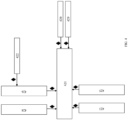
- FIG. 4 illustrates a preferred embodiment of applying the polyionic material(s) onto the surface of the particulates at a final destination point using dual belt conveyor 421.
- the final destination point in FIG. 4 is a wellsite.
- uncoated (or untreated) particulate may be unloaded from one or more transport vehicles (illustrated as transport vehicle 422) into storage receptacles 426 and 428 as well as 423 and 425.
- a conveyor is typically used to deliver particulate into the storage receptacles from the transported vehicle.
- Storage receptacles 426 and 428 are illustrated as being on opposite sides of dual belt conveyor 421 from storage receptacles 423 and 425.
- the polyionic material may be applied onto the surface of the particulates as the particulates are fed into the storage container (shown as particulate being loaded into storage receptacle 426 from transport vehicle 422). Likewise, the polyionic material(s) may be coated onto the particulates as they are transferred from the storage receptacles by a conveyor onto dual belt or T-belt conveyor 421.
- the T-belt conveyor runs transversely where the sand particulates are collected from the multiple storage receptacles.
- a conveyor belt may run from the bottom of the storage receptacle to the T-belt conveyor.
- Coating of the polyionic material(s) onto the surface of the particulates may also occur during transfer of the particulates on conveyor 421 into the hopper of one or more mixing blenders at the wellsite, illustrated in FIG. 4 as dual blenders 420 and 429.
- FIG. 5 represents an illustration of a representative method of applying a polyelectrolyte layer onto at least a portion of the surface of particulates.
- sand particulates are fed into a storage receptacle 553, such as a Sand King, through transport tube 580 via line 570.
- FIG. 5 shows polyelectrolyte being fed into spray nozzle or spray bar 558 through line 572 and impinges on the sand particulates inside storage receptacle 553.
- FIG. 5 further shows the polyelectrolyte exiting stationary spray bar 558 at exit port 576 as the sand particulates exit through port 578 from transport tube 580.
- FIG. 5 further illustrates sand particulates 583 exiting storage receptacle 553 through exit port 582.
- Sand particulates 583 traverse pathway 586 and enter onto moving conveyor 580.
- Spray arm 590 may extend from spray bar 558 and polyelectrolyte may be sprayed onto sand particulates 583 as the sand particulates are moved along pathway 586.
- Spray arm 590 may be stationary or may be moveable as the sand particulates move along pathway 586.
- spray arm 592 may extend from spray bar 558 and polyelectrolyte may be applied onto the sand particulates as they traverse down moving conveyor 580 through spray arm extension 595.
- the polyelectrolyte may be applied onto the sand particulates through spray arm extension 596 as the sand particulates move off of moving conveyor 580 into mixing blender 598. From blender 598 the coated particulates may be fed through tubing 594 downhole.
- FIG. 6 represents pressure sprayer 600 for applying the polyelectrolyte onto the surface of sand particulates.
- polyelectrolyte may be fed through line 621 and pressurized air through feed line 622. Air atomizing nozzles on the spray bar and spray arms and compressed air provide very small drops of polyionic material onto the particulate. The polyionic material moves under pressure through spray bar 630 which bifurcates into pathway 632 and pathway 633. Horseshoe bars extend from pathway 632 and pathway 633 and provide multiple entry ports (634a, 634b, 634c, 634d, 634e and 634f) of polyelectrolyte into the interior of sprayer housing 615.
- Polyelectrolyte entry ports 655a, 655b, 655c and 655d into sprayer housing 615 may further appear on the uppermost portion of the sprayer housing from a spray bar (not shown).
- sand particulates shown as 626A, 626B, 626C and 626D
- polyelectrolyte is sprayed onto the particulates.
- At least a portion of the surface of the particulates may be coated with the polyelectrolyte once exiting the housing as coated particulates 646A, 646B, 646C and 646D.
- a common method of excavating frac sand from sand mine 710 is by the use of large tracked excavators or front end loaders.
- Sand 714 extracted from sandstone with the front end loader is typically then dumped into transport vehicle 716 for transport to processing facility 718 or placed onto conveyor belt 720 for transit to processing facility 718.
- Processing facility 718 may be at the site of sand mine 710 or remote from sand mine 710.
- FIG. 7 illustrates coating of the polyionic material(s) may be applied (designated by the symbol • onto at least a portion of the surface of the sand particulates) during loading of the extracted raw sand onto transport vehicle 716, during unloading of transported sand particulates 712 to processing facility 718, during loading of sand particulates from sand mine 710 onto conveyor belt 720 or during transit of the sand particulates on conveyor belt 720 into processing facility 718.
- the extracted raw sand is typically further processed. Processing of the raw sand may or may not be on-site of the mine. Thus, the raw sand (optionally coated with a polyionic material(s)) may be transferred to an off-site processing area.
- the raw excavated sand is illustrated as being subjected to a washing process 724 in order to remove fine particles from sand particulates. Typically, washing is done by spraying the sand with water as it is carried over a vibrating screen. The fine particles are washed off the sand as the coarse particulates are carried along the screen by the vibration.
- wash solution 726 fed into the washer may contain the polyionic material(s).
- Washed extracted sand 728 may contain the polyionic material(s) on at least a portion of its surface.
- washing process 724 may include the use of an upflow clarifier comprising a tank. Water (optionally with the polyionic material(s)) and sand may be continuously directed into the tank. Overflow water along with the fines overflow the tank while the washed sand falls by gravity to the bottom of the tank and is sent for further processing.
- an upflow clarifier comprising a tank. Water (optionally with the polyionic material(s)) and sand may be continuously directed into the tank. Overflow water along with the fines overflow the tank while the washed sand falls by gravity to the bottom of the tank and is sent for further processing.
- Washed sand 728 may then be sent to surge pile 730 where water adhering to the sand particles infiltrates back into the ground.
- treated sand 732 may be sent to dryer 734.
- the surface of treated sand may optionally be coated with polyionic material(s).
- dryer 734 the sand is typically dried in a drum as hot air 736 is blasted into the drum. Fins inside the drum may agitate the sand and carry it forward through the dryer. When it reaches the end of the drum the sand is typically cooled.
- Washed sand particulates are then typically sorted to isolate suitable sand meeting API specifications as frac sand.
- the washed sand (optionally dried and/or treated) is cooled prior to being subjected to treatment in sorter 740.
- Sorter 740 is typically one or more perforated sieves, screens or plates with different hole diameters or openings to separate the particles according to size.
- FIG. 7 illustrates sorting of dried sand 738 though sand 739 may pass from surge pile 730 directly into sorter 740.
- sorter 740 particulates of sand unsuitable for use in fracturing are separated. At least a portion of the surface of the sand particulates may be treated with the polyionic material(s) prior to being fed into sorter 740.
- screened frac sand 742 may be treated with the polyionic material(s) after exiting sorter 740.
- the sand may be treated with the polyionic material(s) prior to being sorter, as it passes through the sorter or after being sorted.
- Storage location 744 may be a storage container, such as a silo, as well as an open location (such as a sand pile).
- the sorted sand may be treated with the polyionic material(s) during such movement.
- the transport vehicle such as transport vehicle 322 in FIG. 3
- at least a portion of the surface of the sand may be coated with the polyionic material(s).
- a polyelectrolyte layer may be coated onto the particulate in the form of multi-layers of oppositely charged like charged layers, each layer comprising counterions to the polyionic material of the polyelectrolyte layer which is adjacent to it, i.e., the polyionic material in a layer has charge opposite to the charge of the polyionic material as its adjacent layer(s).
- the innermost layer to the particulate i.e., the layer immediately adjacent to the particulate
- the top layer is composed of polyionic material which is counterions to the polyionic material in the bottom layer.
- the bottom layer and the top layer constitute the polyelectrolyte bilayer. When more than two layers constitute the polyelectrolyte then each layer between the bottom layer and the top layer has a charge opposite to the layer to which it is adjacent.
- the polyelectrolyte is a bi-layer and one or more polyelectrolyte bilayers are coated onto the surface of the particulate. Each successive polyelectrolyte bilayer would be coated onto the first polyelectrolyte layer which is adjacent to the particulate.
- Each additional polyelectrolyte bilayer consists of a bottom layer composed of a polyionic material and a top layer composed of a second polyionic material wherein the polyionic material in the bottom layers and top layers are oppositely charged.
- Each polyelectrolyte multi-layer is laid onto the particulate in succession such as in a self-assembly.
- the polyionic material in the bottom layer of each successive polyelectrolyte multi-layer has a charge which is opposite to the charge of the polyionic material in the top layer to which the successive polyelectrolyte multi-layer is adjacent.
- the polyionic material in the bottom layer of the third polyelectrolyte bilayer is opposite to the charge of the polyionic material in the top layer of the second polyelectrolyte bilayer.
- the charge of the polyionic material in the bottom polyionic layer of the fourth polyelectrolyte bilayer is opposite to the charge of the polyionic material of the top layer of the third polyelectrolyte bilayer and so on.
- the polyionic material of the bottom layer of the first polyelectrolyte bilayer coated onto the particulate have a charge which is the opposite to the charge of the surface of the particulate.
- the polyionic material of the top layer of the first polyelectrolyte bilayer is a counterion to the polyionic material of the bottom layer.
- the polyionic material of the bottom layer of the first polyelectrolyte bilayer may be positively charged. This would be the case, for example, where the surface of the particulate carries a negative charge.
- the polyionic material of the top layer of the first polyelectrolyte bilayer would thus carry a negative charge.
- the second top layer is often desirable in order to seal or embed the negatively charged polyionic material of the first top coating within the matrix defined by the first top layer and the bottom layer of the first polyelectrolyte layer.
- the bottom layer may be composed of positively charged polyionic material
- the first top layer may be composed of negatively charged polyionic material
- the second top layer would then be composed of positively charged polyionic material.
- the polyionic material of the bottom layer of a second polyelectrolyte bilayer when present, would be of a negative charge.
- nanoparticles in the polyionic solutions or in a fluid containing a polycationic polymer in order improve the performance of the deposited coating.
- the nanoparticles may be applied separately onto the particulate as alternating layers.
- nanoparticles are deposited along with the polyionic material or polycationic polymer onto the surface of the particulate, it is desirable that they have a surface charge allowing them to be deposited with and to bind to the polyionic materials or polycationic polymer. Any type of nanoparticle that has a surface charge capable of binding with the depositing polyelectrolytes or polycationic polymer may be used in accord with the principles of the disclosure.
- the nanoparticle may be a clay (such as bentonite and smectite clays), double layered hydroxides, carbon nanotubes, graphene oxide, metal phosphates (such as zirconium and titanium phosphate), metal sulfides (such as WS 2 , TaS 2 , TiS 2 ), metal oxides (such as alumina, silica, magnesium oxide, or zinc oxide.)
- the amount of nanoparticles included in a fluid solution containing the polyionic materials or polycationic polymer may be between from about 0.01 to about 15, preferably from about 0.05 to about 10, volume percent.
- a composite of coated multi layers of polyelectrolyte onto the particulate may be prepared by merely mixing two or more polyionic materials of opposite charges together in water. The aqueous mixture may then be deposited onto the surface of the particulate and the composite, then dried. During the process, polyelectrolytes of opposite charges aggregate with each other. All or a portion of the surface of the particulate may be covered by a polyelectrolyte layer having polyionic materials of a charge counter to the charge of the surface of the particulate.
- All or a portion of the polyelectrolyte layer adjacent to the surface of the particulate may be covered by a second polyelectrolyte layer having a charge opposite to the charge of the polyelectrolyte adjacent to the surface of the particulate.
- a succession of polyelectrolyte layers containing polyionic materials may be deposited onto the composite, each successive polyelectrolyte layer comprising polyionic materials having a charge opposite to the charge of the polyionic material of the polyelectrolyte layer adjacent to it.
- the thickness of any polyelectrolyte layer will be less than about 50 nm, more typically from 5 nm to about 25 nm.
- the particle size of the sand particulates coated with the polyionic polymer and the particle size of the sand particulates without a coating are substantially the same (typically plus or minus 10%).
- the particle size of the polyionic material and the particulates is from about 50 ⁇ m to about 2,000 ⁇ m.
- the particulate Normally, between from about 25 to 80 percent of the surface of the particulate is coated with the polyelectrolyte layer and between from about 25 to 80 percent of each polyelectrolyte surface is coated with a successively applied polyelectrolyte coating.
- the amount of a successive polyelectrolyte layer applied to an adjacent polyelectrolyte layer is the amount to counter the charges of the polyionic material to which the successive polyelectrolyte layer is being applied. As such, a 1:1 ratio of negative to positive charges is preferred.
- the composite may further be prepared by a "layer-by-layer” methodology wherein each layer of a material is non-covalently bond to another layer of a different material.
- the composite may be prepared by first contacting the particulate with a first coating solution which contains the polyionic material of the bottom layer in order to non-covalently apply the innermost layer of the polyionic material onto the surface of the particulate.
- a first coating solution which contains the polyionic material of the bottom layer in order to non-covalently apply the innermost layer of the polyionic material onto the surface of the particulate.
- the amount of polyionic material in a coating solution as defined herein is between from about 0.02 to about 2 percent by weight, typically between from about 0.05 to about 1 percent by weight.
- the particulate having the innermost layer of the polyionic material attached to its surface is then contacted with a second coating solution containing the polyionic material comprising the top layer.
- the combination of the two layers of polyionic material forms a first polyelectrolyte bilayer on top of the particulate; the first polyelectrolyte bilayer consisting of the bottom or innermost layer to the particulate composed of a first polyionic material and a top layer of a polyionic material on top of the innermost layer; the second polyionic material having charges opposite of the charges of the first polyionic material. Additional layers may then be added to the particulate by further incorporating steps of contacting the particulate having the first polyelectrolyte bilayer with a third coating solution.
- the third coating solution contains a third polyionic material having a charge which is opposite to the charge of the second polyionic material.
- the third polyionic material may be the same as the first polyionic material or may be another polyionic material with the same charge as the first polyionic material.
- the third polyionic layer is thus formed on top of the first polyelectrolyte bilayer.
- a fourth polyionic coating may then be applied onto the third polyionic layer on the particulate in order to form a second polyelectrolyte bilayer composed of the third polyionic material and the fourth polyionic material.
- the fourth polyionic material has a charge opposite to the charge of the third polyionic material.
- One or more rinsing steps may be included during the process of making the composite, especially between steps of applying successive polyionic coating layers containing polyionic materials of unlike charges.
- the rinsing steps are carried out by contacting the particulate with a rinsing solution.
- the rinsing solution may be an aqueous solution.
- the surface of the particulate may need to be charged making it capable of having electrostatic interactions with the polyionic material.
- a proppant such as sand this step may be unnecessary.
- Sand is largely composed of silica (SiO 2 ), which has Si-O - groups or Si-OH groups that readily hydrolyze, found along its surface. These Si-O - groups allow for the first layer polyelectrolyte to bind.
- Other types of proppant may be neutrally charged at their surface and, hence, not capable forming a substantial electrostatic interaction to bind with the first polyelectrolyte layer. These proppants would have to undergo an initial step to place a charge on their surface.
- a proppant may need to undergo a silylation reaction placing Si-OH groups along its surface.
- the particulate coating that eliminates sharp edges on the particulate and functions as a lubricant to materially reduce mechanical erosion of the pumping components.
- the coated particulate will have a low friction factor and high impact resistance that renders it resistant to chipping and shattering.
- the layers of polyionic material bind to the surface of the particulate and to one another substantially through electrostatic forces.
- polyionic materials forming the assembly coated onto the surface of the particulates be performed at a single location, different polyelectrolyte layers may be applied onto the particulate at multiple locations.
- the particulate to be coated with a polycationic material in Route 3 during loading of the particulate into storage receptacle 353 from transport vehicle 1 and then a polyanionic material during loading of the polycationic coated particulate onto transport vehicle 354.
- the composites defined herein are particularly effective in hydraulic fracturing as well as sand control fluids such as water, salt brine, slickwater such as slick water fracture treatments, low concentration polymer gel fluids (linear or crosslinked), foams (with gas) fluid, liquid gas such as liquid carbon dioxide fracture treatments for deeper proppant penetration, treatments for water sensitive zones, and treatments for gas storage wells.
- sand control fluids such as water, salt brine, slickwater such as slick water fracture treatments, low concentration polymer gel fluids (linear or crosslinked), foams (with gas) fluid, liquid gas such as liquid carbon dioxide fracture treatments for deeper proppant penetration, treatments for water sensitive zones, and treatments for gas storage wells.
- the composites may be mixed and pumped during any desired portion of a well treatment such as hydraulic fracturing treatment or sand control treatment and may be mixed in any desired concentration with a carrier fluid.
- Suitable carrier fluids may be used in combination with gelling agents, crosslinking agents, gel breakers, surfactants, foaming agents, demulsifiers, buffers, clay stabilizers, acids, or mixtures thereof.
- the use of the composites as a proppant advantageously provides for substantially improved overall system performance in stimulation procedure, such as hydraulic fracturing applications, as well as other well treating applications such as sand control.
- the composites When used in hydraulic fracturing, the composites may be injected into a subterranean formation in conjunction with a hydraulic fracturing treatment or other treatment at pressures sufficiently high enough to cause the formation or enlargement of fractures.
- Other well treating applications may be near wellbore in nature (affecting near wellbore regions) and may be directed toward improving wellbore productivity and/or controlling the production of fracture proppant or formation sand.
- Particular examples include gravel packing and "frac-packs.”
- such particles may be employed alone as a fracture proppant/sand control particulate, or in mixtures in amounts and with types of fracture proppant/sand control materials, such as conventional fracture or sand control particulate.
- a gravel pack operation may be carried out on a wellbore that penetrates a subterranean formation to prevent or substantially reduce the production of formation particles into the wellbore from the formation during production of formation fluids.
- the subterranean formation may be completed so as to be in communication with the interior of the wellbore by any suitable method known in the art, for example by perforations in a cased wellbore, and/or by an open hole section.
- a screen assembly such as is known in the art may be placed or otherwise disposed within the wellbore so that at least a portion of the screen assembly is disposed adjacent the subterranean formation.
- a slurry including the composites and a carrier fluid may then be introduced into the wellbore and placed adjacent the subterranean formation by circulation or other suitable method so as to form a fluid-permeable pack in an annular area between the exterior of the screen and the interior of the wellbore that is capable of reducing or substantially preventing the passage of formation particles from the subterranean formation into the wellbore during production of fluids from the formation, while at the same time allowing passage of formation fluids from the subterranean formation through the screen into the wellbore.
- the sand control method may use the composites in accordance with any method in which a pack of particulate material is formed within a wellbore that it is permeable to fluids produced from a wellbore, such as oil, gas, or water, but that substantially prevents or reduces production of formation materials, such as formation sand, from the formation into the wellbore.
- a gravel pack screen may be introduced into a wellbore at pressures below, at or above the fracturing pressure of the formation, such as frac pack, and/or may be employed in conjunction with resins such as sand consolidation resins is so desired.
- the composites defined herein may be used in the corrosion protection of equipment, erosion/abrasion resistance of surfaces, chemical reaction delay mechanisms and other areas where a protective coating is beneficial.
- the composite may also reduce wear in pumping components, such as pump heads, and downhole tools, completion tubing and casing, and related hardware during operations.
- Example 1 To form the coating, the sand was placed in an aqueous solution of 0.5% poly(allylamine hydrochloride) and 0.1% sodium chloride. The solution was decanted and the sand was rinsed. The sand was then placed in an aqueous solution of 0.08% poly(sodium styrene sulfonate). The solution was then decanted and the coated sand was rinsed.
- Example 2 To form the coating, the sand was placed in an aqueous solution of 0.5% poly(allylamine hydrochloride) and 0.1% sodium chloride. The solution was decanted and the sand was rinsed. The sand was then placed in an aqueous solution of 0.08% poly(sodium-4-styrene sulfonate) and 0.2% bentonite nanoclay. The solution was then decanted and the treated sand was then placed into an aqueous solution of 0.5% poly(allylamine hydrochloride) and 0.1% sodium chloride.
- the solution was then decanted and the coated sand was rinsed to form a polyelectrolyte bilayer (first polyelectrolyte bilayer) on the sand particulate.
- a second polyelectrolyte bilayer was further coated onto particulates coated with the first polyelectrolyte bilayer by placing such coated particulates in an aqueous solution of 0.08% poly(sodium-4-styrene sulfonate) and 0.2% bentonite nanoclay.
- the solution was then decanted and the treated sand was then placed into an aqueous solution of 0.5% poly(allylamine hydrochloride) and 0.1% sodium chloride.
- FIG. 1 illustrates that crush resistance of the coated particulate was dramatically improved by coating of the particulate with one or more polyelectrolyte bilayers.
- FIG. 1 shows that one polyelectrolyte bilayer reduces fines production by almost one half and that ten layers of polyelectrolyte bilayers reduce fines to almost one third as compared to uncoated sand.
- Example 3 A self-assembling coating having alternating layers of positively-charged [poly(diallyldimethylammonium chloride)] and negatively-charged (sodium poly styrene sulfonate) on frac sand proppant was prepared from an aqueous-based system. Approximately 1 volume percent of each of the two water-soluble polymers were combined in distilled water. About 200 mL of the resulting aqueous solution was then mixed with 250 g of frac sand and shaken for two minutes. During this shaking the polymers self-assembled into positive and negative layers over the surface of the sand grains. When the aqueous solution was then drained from the sand the polymer coating remain adhered to individual grains.
- the water-polymer solution was shown to be reusable multiple times.
- 250 g of frac sand was also shaken with 200 mL of deionized water which did not contain any polymers but simply rinsed away dust particles.
- the ability of the polymer coating to reduce dust was tested by measuring the turbidity of water shaken with a known amount of frac sand.
- non-rolled frac sand had a turbidity of 212 FAU if not rinsed and 66 FAU if rinsed once with deionized water. This corresponds to reduction in dust turbidity by the polymer-coated sand by 85% and 53% versus the non-rolled sands.
- Example 4 About 0.454 kg (1 lb) of sand was sprayed with various amounts of an aqueous solution containing 0.5% of poly (diallyldimethylammonium chloride) and 0.4% sodium chloride, and then mixed for 20 minutes prior to drying. The resulting composite particles were then tested for the ability in producing less dust than non-coated particles. The ability of the polymeric coating to reduce dust was tested by measuring the turbidity of the samples before and after surface modification. The turbidity tests were performed accordingly to API RP 60, three data points were recorded for each sample than averaged. The results are tabulated in Table II. The benefits of surface treating the sand are clearly seen by the reduction in fines up to 90%.
Landscapes
- Chemical & Material Sciences (AREA)
- Engineering & Computer Science (AREA)
- Organic Chemistry (AREA)
- Materials Engineering (AREA)
- Ceramic Engineering (AREA)
- Structural Engineering (AREA)
- Civil Engineering (AREA)
- General Life Sciences & Earth Sciences (AREA)
- Life Sciences & Earth Sciences (AREA)
- Road Paving Structures (AREA)
- Application Of Or Painting With Fluid Materials (AREA)
- Processes Of Treating Macromolecular Substances (AREA)
- Coating Of Shaped Articles Made Of Macromolecular Substances (AREA)
- Mold Materials And Core Materials (AREA)
- Silicon Compounds (AREA)
- Processing Of Solid Wastes (AREA)
Claims (12)
- Procédé de suppression de production de poussière à partir de particules de sable au niveau d'un site de forage comprenant :(a) l'application sur au moins une partie de la surface des particules de sable d'un polymère polyionique conformément à au moins l'un parmi (i) à (ix) ci-dessous :(i) pendant l'excavation des particules de sable d'une mine de sable ;(ii) pendant le traitement de sable évacué d'une mine de sable ;(iii) après que les particules de sable ont été transportées à partir de la mine ;(iv) pendant le chargement des particules de sable d'une mine de sable sur un véhicule de transport ou dans un réceptacle de stockage ;(v) pendant le transit des particules de sable d'une mine de sable vers une installation de traitement ;:;(vi) pendant le transbordement des particules de sable d'un véhicule de transport vers un autre véhicule de transport ou un réceptacle de stockage ;(vii) pendant le transbordement des particules de sable d'un réceptacle de stockage vers un véhicule de transport ou un autre réceptacle de stockage ;(viii) après que les particules de sable ont été déchargées d'un véhicule de transport dans un ou plusieurs réceptacles de stockage, mais avant le chargement des particules de sable dans un malaxeur au niveau du site de forage ; et(ix) à mesure que les particules de sable sont chargées dans un malaxeur au niveau du site de forage ;(b) l'agitation des particules de sable ayant le polymère polyionique appliqué à celles-ci au niveau d'un site de forage ; et(c) la réduction de la quantité de poussière produite ou libérée lors de l'agitation des particules au niveau du site de forage par la présence du polymère polyionique appliqué sur la surface des particules ;et dans lequel :(1) le polymère polyionique est appliqué sur les particules de sable dans des gouttelettes d'eau par le biais d'une buse de pulvérisation ;(2) le polymère polyionique est appliqué sur les particules de sable dans des gouttelettes d'eau à l'aide d'un convoyeur à double bande ;(3) le polymère polyionique est appliqué pendant l'excavation de sable d'une mine ou par hydrosoufflage de grès à l'aide d'un courant d'eau contenant le polymère polyionique ;(4) le polymère polyionique est appliqué sur les particules de sable à la suite d'un lavage du sable par pulvérisation d'eau sur le sable à mesure que le sable est transporté par-dessus un crible vibrant ;(5) le polymère polyionique est polycationique et polyanionique dans lequel le polymère polycationique est appliqué pendant le chargement des particules de sable dans un réceptacle de stockage et le polymère polyanionique est par la suite appliqué pendant le chargement des particules de sable à revêtement polycationique sur un véhicule de transport ; ou(6) le polymère polyionique est appliqué sous forme d'air comprimé sur la surface des particules de sable par le biais de buses d'atomisation d'air d'une rampe de pulvérisation.
- Procédé selon la revendication 1, dans lequel le polymère polyionique est un polymère polycationique.
- Procédé selon la revendication 2, dans lequel le polymère polycationique est choisi dans le groupe constitué par :(a) un homo- ou co-polymère de chlorhydrate de polyallylamine, un sel ou un dérivé quaternisé, comprenant facultativement des motifs de modification ;(b) une polyéthylène-imine, un sel ou un dérivé quaternisé de celle-ci ;(c) un homo- ou co-polymère de polyvinylamine, un sel ou un dérivé quaternisé de celui-ci comprenant facultativement des motifs de modification ;(d) un poly[vinylbenzyl-tri(alkyl en C1 à C4)sel d'ammonium] ou un dérivé quaternisé de celui-ci ;(e) un polymère résultant d'une réaction de polymérisation par étapes (quaternisation) entre un dihalogénure et une N,N,N',N'-tétra-(alkyl en C1 à C4)-alkylènediamine ;(f) un homo- ou co-polymère de poly(vinylpyridine) ou de poly(sel de vinylpyridinium) ou un dérivé quaternisé de celui-ci ;(g) un polymère par l'intermédiaire d'une polymérisation par formation de cycle d'halogénure de N,N-diallyl-N,N-di(alkyl en C1 à C4)ammonium, comprenant des motifs de la formule :
 (h) un homo- ou co-polymère d'un acrylate ou méthacrylate di(alkyl en C1 à C4 alkyl)aminoéthyle quaternisé ;(i) un polyaminoamide (PAMAM), un sel ou un dérivé quaternisé de celui-ci ; et(j) des mélanges de quelconques de (a) à (i).
 - Procédé selon la revendication 1, dans lequel les particules de sable excavées sont soumises à un lavage avec un fluide de lavage comprenant le polymère polyionique.
- Procédé selon la revendication 1, dans lequel les particules de sable excavées sont soumises à un lavage et sont ensuite séchées et dans lequel en outre au moins une partie de la surface des particules de sable lavées est traitée avec le polymère polyionique pendant le transfert des particules de sable lavées vers un séchoir.
- Procédé selon la revendication 1, dans lequel les particules de sable excavées sont calibrées dans une calibreuse et dans lequel au moins une partie de la surface des particules de sable excavées est revêtue du polymère polyionique avant d'être introduites dans la calibreuse, alors qu'elles sont dans la calibreuse ou après sortie de la calibreuse.
- Procédé selon la revendication 1, dans lequel les particules de sable excavées sont soumises à un lavage puis sont calibrées dans une calibreuse puis transférées vers une localisation de stockage et dans lequel au moins une partie de la surface des particules de sable calibrées est revêtue du polymère polyionique avant ou pendant le transfert vers la localisation de stockage.
- Procédé selon la revendication 1, dans lequel le polymère polyionique est appliqué sur au moins une partie des particules de sable à mesure que les particules de sable sont transportées vers le véhicule de transport ou dans un réceptacle de stockage sur un convoyeur en mouvement.
- Procédé selon la revendication 1, dans lequel le polymère polyionique est soit :(a) appliqué sur au moins une partie des particules de sable pendant le transbordement des particules de sable d'un premier véhicule de transport vers un second véhicule de transport ;(b) transporté du premier véhicule de transport sur un convoyeur vers le second véhicule de transport et dans lequel en outre le polymère polyionique est appliqué sur les particules de sable sur le convoyeur ; ou(c) appliqué sur au moins une partie des particules de sable pendant le transbordement des particules de sable du véhicule de transport vers le réceptacle de stockage.
- Procédé selon la revendication 1, dans lequel le polymère polyionique est appliqué sur au moins une partie des particules de sable après que les particules de sable ont été déchargées d'un véhicule de transport dans un ou plusieurs réceptacles de stockage, mais avant déchargement des particules de sable dans un malaxeur au niveau du site de forage et dans lequel en outre :(a) le polymère polyionique est appliqué sur les particules de sable à mesure que le polymère polyionique entre dans le réceptacle de stockage ; ou(b) les particules de sable sont déchargées du réceptacle de stockage sur un convoyeur et dans lequel le polymère polyionique est appliqué sur la surface d'au moins une partie des particules de sable sur le convoyeur.
- Procédé selon la revendication 1, dans lequel le polymère polyionique est appliqué sur au moins une partie des particules de sable après que les particules de sable ont été déchargées d'un véhicule de transport dans un ou plusieurs réceptacles de stockage, mais avant déchargement des particules de sable dans un malaxeur au niveau du site de forage et dans lequel en outre (i) les particules de sable sont déchargées du réceptacle de stockage sur un convoyeur, (ii) le polymère polyionique est appliqué sur la surface d'au moins une partie des particules de sable sur le convoyeur, (iii) le réceptacle de stockage a une rampe de pulvérisation et (iv) le polymère polyionique est pulvérisé par le biais de la rampe de pulvérisation sur la surface d'au moins une partie des particules de sable.
- Procédé selon la revendication 1, dans lequel le polymère polyionique est appliqué sur au moins une partie des particules de sable à mesure que les particules de sable sont chargées dans un malaxeur au niveau du site de forage et dans lequel en outre les particules de sable sont alimentées dans le malaxeur sur un convoyeur et le polymère polyionique est appliqué sur la surface d'au moins une partie des particules de sable alors que les particules de sable sont sur le convoyeur.
Applications Claiming Priority (2)
| Application Number | Priority Date | Filing Date | Title |
|---|---|---|---|
| US14/875,326 US9637671B2 (en) | 2011-10-27 | 2015-10-05 | Method of suppressing the generation of dust from sand |
| PCT/US2016/060395 WO2017063000A2 (fr) | 2015-10-05 | 2016-11-03 | Composites de sable et leurs procédés d'utilisation pour la lutte contre la poussière |
Publications (3)
| Publication Number | Publication Date |
|---|---|
| EP3359618A2 EP3359618A2 (fr) | 2018-08-15 |
| EP3359618A4 EP3359618A4 (fr) | 2019-06-26 |
| EP3359618B1 true EP3359618B1 (fr) | 2025-05-07 |
Family
ID=58488648
Family Applications (1)
| Application Number | Title | Priority Date | Filing Date |
|---|---|---|---|
| EP16854578.8A Active EP3359618B1 (fr) | 2015-10-05 | 2016-11-03 | Composites de sable et leurs procédés d'utilisation pour la lutte contre la poussière |
Country Status (4)
| Country | Link |
|---|---|
| EP (1) | EP3359618B1 (fr) |
| CA (1) | CA3000954C (fr) |
| CO (1) | CO2018003784A2 (fr) |
| WO (1) | WO2017063000A2 (fr) |
Family Cites Families (7)
| Publication number | Priority date | Publication date | Assignee | Title |
|---|---|---|---|---|
| GB0610000D0 (en) * | 2006-05-19 | 2006-06-28 | Ciba Sc Holding Ag | Suppression of Dust |
| US9127195B1 (en) * | 2010-03-23 | 2015-09-08 | Fritz Industries, Inc. | Method of making a viscous aqueous liquid |
| RU2602250C2 (ru) * | 2011-08-31 | 2016-11-10 | Селф-Саспендинг Проппант Ллс | Самосуспендирующиеся проппанты для гидравлического разрыва пласта |
| US9644140B2 (en) * | 2011-10-27 | 2017-05-09 | Baker Hughes Incorporated | Method of reducing dust with particulates coated with a polycationic polymer |
| US9624377B2 (en) * | 2011-10-27 | 2017-04-18 | Baker Hughes Incorporated | Methods of using sand composites to control dust |
| BR112016010888B1 (pt) * | 2013-11-15 | 2022-06-07 | Rohm And Haas Company | Propante para uso em fraturamento hidráulico, processo para preparar o propante e método para reduzir a geração de poeira associada com operações de fraturamento hidráulico |
| CN103772534B (zh) * | 2014-01-16 | 2016-03-02 | 兰州大学 | 一种固沙固土抑尘的高分子材料 |
-
2016
- 2016-11-03 EP EP16854578.8A patent/EP3359618B1/fr active Active
- 2016-11-03 WO PCT/US2016/060395 patent/WO2017063000A2/fr not_active Ceased
- 2016-11-03 CA CA3000954A patent/CA3000954C/fr not_active Expired - Fee Related
-
2018
- 2018-04-10 CO CONC2018/0003784A patent/CO2018003784A2/es unknown
Also Published As
| Publication number | Publication date |
|---|---|
| EP3359618A2 (fr) | 2018-08-15 |
| WO2017063000A2 (fr) | 2017-04-13 |
| EP3359618A4 (fr) | 2019-06-26 |
| CA3000954A1 (fr) | 2017-04-13 |
| CA3000954C (fr) | 2021-01-05 |
| CO2018003784A2 (es) | 2018-07-10 |
| WO2017063000A3 (fr) | 2018-02-22 |
Similar Documents
| Publication | Publication Date | Title |
|---|---|---|
| US9637671B2 (en) | Method of suppressing the generation of dust from sand | |
| US9624377B2 (en) | Methods of using sand composites to control dust | |
| US9644140B2 (en) | Method of reducing dust with particulates coated with a polycationic polymer | |
| AU2006248810B2 (en) | Methods of treating surfaces in subterranean formations | |
| AU2013249743B2 (en) | Self-suspending proppants for hydraulic fracturing | |
| US9644139B2 (en) | Self-suspending proppants for hydraulic fracturing | |
| US10472943B2 (en) | Self-suspending proppants for hydraulic fracturing | |
| US7591313B2 (en) | Methods of treating particulates and use in subterranean formations | |
| EP2751387B1 (fr) | Agents de soutènement auto-suspendus pour fracturation hydraulique | |
| CN105793386A (zh) | 用于支撑剂固体的闪涂处理 | |
| US20140014348A1 (en) | Self-suspending proppants for hydraulic fracturing | |
| CN106255737B (zh) | 耐磨耗支撑剂复合物及其组合物质 | |
| WO2013192634A2 (fr) | Agents de soutènement à auto-suspension pour fracturation hydraulique | |
| EP2440630A1 (fr) | Matières particulaires préenrobées d'agent collant | |
| CN107002487A (zh) | 包含油井处理剂涂料的支撑剂 | |
| EP3359618B1 (fr) | Composites de sable et leurs procédés d'utilisation pour la lutte contre la poussière | |
| JP2001525023A (ja) | 導管清掃材料及び方法 | |
| US20180355241A1 (en) | Dust free inorganic particles and method of making same | |
| WO1998040606A1 (fr) | Traitement d'un puits avec des particules | |
| CA2973137A1 (fr) | Solides d'agents de soutenement mis en contact avec des materiaux absorbant l'eau et procedes de fabrication associes | |
| CN116590000A (zh) | 一种以赤泥为添加剂的压裂支撑剂及其制备方法 | |
| US20200131430A1 (en) | Method of consolidating subterranean formations using cationic and anionic and/or non-ionic polymers |
Legal Events
| Date | Code | Title | Description |
|---|---|---|---|
| STAA | Information on the status of an ep patent application or granted ep patent |
Free format text: STATUS: THE INTERNATIONAL PUBLICATION HAS BEEN MADE |
|
| PUAI | Public reference made under article 153(3) epc to a published international application that has entered the european phase |
Free format text: ORIGINAL CODE: 0009012 |
|
| STAA | Information on the status of an ep patent application or granted ep patent |
Free format text: STATUS: REQUEST FOR EXAMINATION WAS MADE |
|
| 17P | Request for examination filed |
Effective date: 20180503 |
|
| AK | Designated contracting states |
Kind code of ref document: A2 Designated state(s): AL AT BE BG CH CY CZ DE DK EE ES FI FR GB GR HR HU IE IS IT LI LT LU LV MC MK MT NL NO PL PT RO RS SE SI SK SM TR |
|
| AX | Request for extension of the european patent |
Extension state: BA ME |
|
| DAV | Request for validation of the european patent (deleted) | ||
| DAX | Request for extension of the european patent (deleted) | ||
| A4 | Supplementary search report drawn up and despatched |
Effective date: 20190523 |
|
| RIC1 | Information provided on ipc code assigned before grant |
Ipc: C09K 3/22 20060101AFI20190517BHEP Ipc: C04B 14/06 20060101ALI20190517BHEP |
|
| STAA | Information on the status of an ep patent application or granted ep patent |
Free format text: STATUS: EXAMINATION IS IN PROGRESS |
|
| 17Q | First examination report despatched |
Effective date: 20200629 |
|
| RIC1 | Information provided on ipc code assigned before grant |
Ipc: C04B 14/06 20060101ALI20210914BHEP Ipc: C09K 8/80 20060101ALI20210914BHEP Ipc: C09K 3/22 20060101AFI20210914BHEP |
|
| P01 | Opt-out of the competence of the unified patent court (upc) registered |
Effective date: 20230526 |
|
| GRAP | Despatch of communication of intention to grant a patent |
Free format text: ORIGINAL CODE: EPIDOSNIGR1 |
|
| STAA | Information on the status of an ep patent application or granted ep patent |
Free format text: STATUS: GRANT OF PATENT IS INTENDED |
|
| INTG | Intention to grant announced |
Effective date: 20250220 |
|
| GRAS | Grant fee paid |
Free format text: ORIGINAL CODE: EPIDOSNIGR3 |
|
| GRAA | (expected) grant |
Free format text: ORIGINAL CODE: 0009210 |
|
| STAA | Information on the status of an ep patent application or granted ep patent |
Free format text: STATUS: THE PATENT HAS BEEN GRANTED |
|
| AK | Designated contracting states |
Kind code of ref document: B1 Designated state(s): AL AT BE BG CH CY CZ DE DK EE ES FI FR GB GR HR HU IE IS IT LI LT LU LV MC MK MT NL NO PL PT RO RS SE SI SK SM TR |
|
| RAP3 | Party data changed (applicant data changed or rights of an application transferred) |
Owner name: BAKER HUGHES HOLDINGS LLC |
|
| REG | Reference to a national code |
Ref country code: GB Ref legal event code: FG4D |
|
| REG | Reference to a national code |
Ref country code: CH Ref legal event code: EP |
|
| REG | Reference to a national code |
Ref country code: DE Ref legal event code: R096 Ref document number: 602016092187 Country of ref document: DE |
|
| REG | Reference to a national code |
Ref country code: IE Ref legal event code: FG4D |
|
| REG | Reference to a national code |
Ref country code: NL Ref legal event code: MP Effective date: 20250507 |
|
| PG25 | Lapsed in a contracting state [announced via postgrant information from national office to epo] |
Ref country code: PT Free format text: LAPSE BECAUSE OF FAILURE TO SUBMIT A TRANSLATION OF THE DESCRIPTION OR TO PAY THE FEE WITHIN THE PRESCRIBED TIME-LIMIT Effective date: 20250908 Ref country code: ES Free format text: LAPSE BECAUSE OF FAILURE TO SUBMIT A TRANSLATION OF THE DESCRIPTION OR TO PAY THE FEE WITHIN THE PRESCRIBED TIME-LIMIT Effective date: 20250507 Ref country code: FI Free format text: LAPSE BECAUSE OF FAILURE TO SUBMIT A TRANSLATION OF THE DESCRIPTION OR TO PAY THE FEE WITHIN THE PRESCRIBED TIME-LIMIT Effective date: 20250507 |
|
| REG | Reference to a national code |
Ref country code: LT Ref legal event code: MG9D |
|
| PG25 | Lapsed in a contracting state [announced via postgrant information from national office to epo] |
Ref country code: GR Free format text: LAPSE BECAUSE OF FAILURE TO SUBMIT A TRANSLATION OF THE DESCRIPTION OR TO PAY THE FEE WITHIN THE PRESCRIBED TIME-LIMIT Effective date: 20250808 |
|
| PG25 | Lapsed in a contracting state [announced via postgrant information from national office to epo] |
Ref country code: NL Free format text: LAPSE BECAUSE OF FAILURE TO SUBMIT A TRANSLATION OF THE DESCRIPTION OR TO PAY THE FEE WITHIN THE PRESCRIBED TIME-LIMIT Effective date: 20250507 Ref country code: PL Free format text: LAPSE BECAUSE OF FAILURE TO SUBMIT A TRANSLATION OF THE DESCRIPTION OR TO PAY THE FEE WITHIN THE PRESCRIBED TIME-LIMIT Effective date: 20250507 |
|
| REG | Reference to a national code |
Ref country code: AT Ref legal event code: MK05 Ref document number: 1792471 Country of ref document: AT Kind code of ref document: T Effective date: 20250507 |
|
| PG25 | Lapsed in a contracting state [announced via postgrant information from national office to epo] |
Ref country code: BG Free format text: LAPSE BECAUSE OF FAILURE TO SUBMIT A TRANSLATION OF THE DESCRIPTION OR TO PAY THE FEE WITHIN THE PRESCRIBED TIME-LIMIT Effective date: 20250507 |
|
| PG25 | Lapsed in a contracting state [announced via postgrant information from national office to epo] |
Ref country code: HR Free format text: LAPSE BECAUSE OF FAILURE TO SUBMIT A TRANSLATION OF THE DESCRIPTION OR TO PAY THE FEE WITHIN THE PRESCRIBED TIME-LIMIT Effective date: 20250507 |
|
| PG25 | Lapsed in a contracting state [announced via postgrant information from national office to epo] |
Ref country code: AT Free format text: LAPSE BECAUSE OF FAILURE TO SUBMIT A TRANSLATION OF THE DESCRIPTION OR TO PAY THE FEE WITHIN THE PRESCRIBED TIME-LIMIT Effective date: 20250507 |
|
| PG25 | Lapsed in a contracting state [announced via postgrant information from national office to epo] |
Ref country code: RS Free format text: LAPSE BECAUSE OF FAILURE TO SUBMIT A TRANSLATION OF THE DESCRIPTION OR TO PAY THE FEE WITHIN THE PRESCRIBED TIME-LIMIT Effective date: 20250807 |
|
| PG25 | Lapsed in a contracting state [announced via postgrant information from national office to epo] |
Ref country code: IS Free format text: LAPSE BECAUSE OF FAILURE TO SUBMIT A TRANSLATION OF THE DESCRIPTION OR TO PAY THE FEE WITHIN THE PRESCRIBED TIME-LIMIT Effective date: 20250907 |
|
| PG25 | Lapsed in a contracting state [announced via postgrant information from national office to epo] |
Ref country code: LV Free format text: LAPSE BECAUSE OF FAILURE TO SUBMIT A TRANSLATION OF THE DESCRIPTION OR TO PAY THE FEE WITHIN THE PRESCRIBED TIME-LIMIT Effective date: 20250507 |
|
| PGFP | Annual fee paid to national office [announced via postgrant information from national office to epo] |
Ref country code: GB Payment date: 20251023 Year of fee payment: 10 |
|
| PGFP | Annual fee paid to national office [announced via postgrant information from national office to epo] |
Ref country code: NO Payment date: 20251024 Year of fee payment: 10 |
|
| PG25 | Lapsed in a contracting state [announced via postgrant information from national office to epo] |
Ref country code: DK Free format text: LAPSE BECAUSE OF FAILURE TO SUBMIT A TRANSLATION OF THE DESCRIPTION OR TO PAY THE FEE WITHIN THE PRESCRIBED TIME-LIMIT Effective date: 20250507 Ref country code: SM Free format text: LAPSE BECAUSE OF FAILURE TO SUBMIT A TRANSLATION OF THE DESCRIPTION OR TO PAY THE FEE WITHIN THE PRESCRIBED TIME-LIMIT Effective date: 20250507 |
|
| PG25 | Lapsed in a contracting state [announced via postgrant information from national office to epo] |
Ref country code: CZ Free format text: LAPSE BECAUSE OF FAILURE TO SUBMIT A TRANSLATION OF THE DESCRIPTION OR TO PAY THE FEE WITHIN THE PRESCRIBED TIME-LIMIT Effective date: 20250507 |
|
| PG25 | Lapsed in a contracting state [announced via postgrant information from national office to epo] |
Ref country code: EE Free format text: LAPSE BECAUSE OF FAILURE TO SUBMIT A TRANSLATION OF THE DESCRIPTION OR TO PAY THE FEE WITHIN THE PRESCRIBED TIME-LIMIT Effective date: 20250507 |
|
| PG25 | Lapsed in a contracting state [announced via postgrant information from national office to epo] |
Ref country code: SK Free format text: LAPSE BECAUSE OF FAILURE TO SUBMIT A TRANSLATION OF THE DESCRIPTION OR TO PAY THE FEE WITHIN THE PRESCRIBED TIME-LIMIT Effective date: 20250507 Ref country code: RO Free format text: LAPSE BECAUSE OF FAILURE TO SUBMIT A TRANSLATION OF THE DESCRIPTION OR TO PAY THE FEE WITHIN THE PRESCRIBED TIME-LIMIT Effective date: 20250507 |
|
| PG25 | Lapsed in a contracting state [announced via postgrant information from national office to epo] |
Ref country code: IT Free format text: LAPSE BECAUSE OF FAILURE TO SUBMIT A TRANSLATION OF THE DESCRIPTION OR TO PAY THE FEE WITHIN THE PRESCRIBED TIME-LIMIT Effective date: 20250507 |
|
| REG | Reference to a national code |
Ref country code: DE Ref legal event code: R097 Ref document number: 602016092187 Country of ref document: DE |
|
| PLBE | No opposition filed within time limit |
Free format text: ORIGINAL CODE: 0009261 |
|
| STAA | Information on the status of an ep patent application or granted ep patent |
Free format text: STATUS: NO OPPOSITION FILED WITHIN TIME LIMIT |
|
| REG | Reference to a national code |
Ref country code: CH Ref legal event code: L10 Free format text: ST27 STATUS EVENT CODE: U-0-0-L10-L00 (AS PROVIDED BY THE NATIONAL OFFICE) Effective date: 20260318 |
|
| 26N | No opposition filed |
Effective date: 20260210 |