EP3359767B1 - Vorrichtung und verfahren zur steuerung der federkraft bei einem türschliesser oder -bediener - Google Patents
Vorrichtung und verfahren zur steuerung der federkraft bei einem türschliesser oder -bediener Download PDFInfo
- Publication number
- EP3359767B1 EP3359767B1 EP16854120.9A EP16854120A EP3359767B1 EP 3359767 B1 EP3359767 B1 EP 3359767B1 EP 16854120 A EP16854120 A EP 16854120A EP 3359767 B1 EP3359767 B1 EP 3359767B1
- Authority
- EP
- European Patent Office
- Prior art keywords
- spring
- housing
- longitudinal axis
- spring collar
- adjusting screw
- Prior art date
- Legal status (The legal status is an assumption and is not a legal conclusion. Google has not performed a legal analysis and makes no representation as to the accuracy of the status listed.)
- Active
Links
Images




Classifications
-
- E—FIXED CONSTRUCTIONS
- E05—LOCKS; KEYS; WINDOW OR DOOR FITTINGS; SAFES
- E05F—DEVICES FOR MOVING WINGS INTO OPEN OR CLOSED POSITION; CHECKS FOR WINGS; WING FITTINGS NOT OTHERWISE PROVIDED FOR, CONCERNED WITH THE FUNCTIONING OF THE WING
- E05F1/00—Closers or openers for wings, not otherwise provided for in this subclass
- E05F1/08—Closers or openers for wings, not otherwise provided for in this subclass spring-actuated, e.g. for horizontally sliding wings
- E05F1/10—Closers or openers for wings, not otherwise provided for in this subclass spring-actuated, e.g. for horizontally sliding wings for swinging wings, e.g. counterbalance
- E05F1/1041—Closers or openers for wings, not otherwise provided for in this subclass spring-actuated, e.g. for horizontally sliding wings for swinging wings, e.g. counterbalance with a coil spring perpendicular to the pivot axis
- E05F1/105—Closers or openers for wings, not otherwise provided for in this subclass spring-actuated, e.g. for horizontally sliding wings for swinging wings, e.g. counterbalance with a coil spring perpendicular to the pivot axis with a compression spring
-
- E—FIXED CONSTRUCTIONS
- E05—LOCKS; KEYS; WINDOW OR DOOR FITTINGS; SAFES
- E05F—DEVICES FOR MOVING WINGS INTO OPEN OR CLOSED POSITION; CHECKS FOR WINGS; WING FITTINGS NOT OTHERWISE PROVIDED FOR, CONCERNED WITH THE FUNCTIONING OF THE WING
- E05F3/00—Closers or openers with braking devices, e.g. checks; Construction of pneumatic or liquid braking devices
- E05F3/04—Closers or openers with braking devices, e.g. checks; Construction of pneumatic or liquid braking devices with liquid piston brakes
- E05F3/10—Closers or openers with braking devices, e.g. checks; Construction of pneumatic or liquid braking devices with liquid piston brakes with a spring, other than a torsion spring, and a piston, the axes of which are the same or lie in the same direction
-
- E—FIXED CONSTRUCTIONS
- E05—LOCKS; KEYS; WINDOW OR DOOR FITTINGS; SAFES
- E05F—DEVICES FOR MOVING WINGS INTO OPEN OR CLOSED POSITION; CHECKS FOR WINGS; WING FITTINGS NOT OTHERWISE PROVIDED FOR, CONCERNED WITH THE FUNCTIONING OF THE WING
- E05F3/00—Closers or openers with braking devices, e.g. checks; Construction of pneumatic or liquid braking devices
- E05F3/04—Closers or openers with braking devices, e.g. checks; Construction of pneumatic or liquid braking devices with liquid piston brakes
- E05F3/10—Closers or openers with braking devices, e.g. checks; Construction of pneumatic or liquid braking devices with liquid piston brakes with a spring, other than a torsion spring, and a piston, the axes of which are the same or lie in the same direction
- E05F3/102—Closers or openers with braking devices, e.g. checks; Construction of pneumatic or liquid braking devices with liquid piston brakes with a spring, other than a torsion spring, and a piston, the axes of which are the same or lie in the same direction with rack-and-pinion transmission between driving shaft and piston within the closer housing
-
- E—FIXED CONSTRUCTIONS
- E05—LOCKS; KEYS; WINDOW OR DOOR FITTINGS; SAFES
- E05Y—INDEXING SCHEME ASSOCIATED WITH SUBCLASSES E05D AND E05F, RELATING TO CONSTRUCTION ELEMENTS, ELECTRIC CONTROL, POWER SUPPLY, POWER SIGNAL OR TRANSMISSION, USER INTERFACES, MOUNTING OR COUPLING, DETAILS, ACCESSORIES, AUXILIARY OPERATIONS NOT OTHERWISE PROVIDED FOR, APPLICATION THEREOF
- E05Y2201/00—Constructional elements; Accessories therefor
- E05Y2201/40—Motors; Magnets; Springs; Weights; Accessories therefor
- E05Y2201/404—Function thereof
- E05Y2201/41—Function thereof for closing
-
- E—FIXED CONSTRUCTIONS
- E05—LOCKS; KEYS; WINDOW OR DOOR FITTINGS; SAFES
- E05Y—INDEXING SCHEME ASSOCIATED WITH SUBCLASSES E05D AND E05F, RELATING TO CONSTRUCTION ELEMENTS, ELECTRIC CONTROL, POWER SUPPLY, POWER SIGNAL OR TRANSMISSION, USER INTERFACES, MOUNTING OR COUPLING, DETAILS, ACCESSORIES, AUXILIARY OPERATIONS NOT OTHERWISE PROVIDED FOR, APPLICATION THEREOF
- E05Y2201/00—Constructional elements; Accessories therefor
- E05Y2201/40—Motors; Magnets; Springs; Weights; Accessories therefor
- E05Y2201/499—Spring tensioners; Tension sensors
-
- E—FIXED CONSTRUCTIONS
- E05—LOCKS; KEYS; WINDOW OR DOOR FITTINGS; SAFES
- E05Y—INDEXING SCHEME ASSOCIATED WITH SUBCLASSES E05D AND E05F, RELATING TO CONSTRUCTION ELEMENTS, ELECTRIC CONTROL, POWER SUPPLY, POWER SIGNAL OR TRANSMISSION, USER INTERFACES, MOUNTING OR COUPLING, DETAILS, ACCESSORIES, AUXILIARY OPERATIONS NOT OTHERWISE PROVIDED FOR, APPLICATION THEREOF
- E05Y2600/00—Mounting or coupling arrangements for elements provided for in this subclass
- E05Y2600/50—Mounting methods; Positioning
- E05Y2600/56—Positioning, e.g. re-positioning, or pre-mounting
- E05Y2600/58—Positioning, e.g. re-positioning, or pre-mounting by using indicators or markings, e.g. scales
-
- E—FIXED CONSTRUCTIONS
- E05—LOCKS; KEYS; WINDOW OR DOOR FITTINGS; SAFES
- E05Y—INDEXING SCHEME ASSOCIATED WITH SUBCLASSES E05D AND E05F, RELATING TO CONSTRUCTION ELEMENTS, ELECTRIC CONTROL, POWER SUPPLY, POWER SIGNAL OR TRANSMISSION, USER INTERFACES, MOUNTING OR COUPLING, DETAILS, ACCESSORIES, AUXILIARY OPERATIONS NOT OTHERWISE PROVIDED FOR, APPLICATION THEREOF
- E05Y2900/00—Application of doors, windows, wings or fittings thereof
- E05Y2900/10—Application of doors, windows, wings or fittings thereof for buildings or parts thereof
- E05Y2900/13—Type of wing
- E05Y2900/132—Doors
Definitions
- the present invention relates generally to door closers or operators that utilize a compression spring to apply force to close a door. More specifically, the present invention relates to a spring adjuster and indicator for use with a door closer or operator, which allows for adjustment of the spring closing force while the door closer housing remains stationary, while also providing a visual indicator of the level of spring compression.
- a typical prior art door closer 120 is shown in Fig. 1 and includes a closer housing 122 that in part defines a substantially cylindrical reservoir, a piston 126 and compression spring 130 biased against the piston 126.
- a rack 138 is attached to the piston 126.
- the rack 138 is driven by a pinion 140 through engagement with the teeth 142 of the pinion 140.
- the pinion 140 is connected to a closer arm assembly (not shown) for operably coupling the door closer 120 to a door.
- FIG. 1 shows the door closer 120 in a position corresponding to a closed door.
- the pinion 140 rotates in an initial direction, transporting the rack 138 and consequently sliding the piston 126 to the right as shown in Fig. 1 .
- the compression spring 130 urges the piston 126 and rack 138 to the left in Fig. 1 .
- the force of the compression spring 130 overcomes the input force from the door and pinion 140 such as when the door is released, the compression spring 130 will force the piston 126 to the left in Fig. 1 , and the pinion 140 will rotate in a direction opposite the initial direction and the door closer 120 will act to close the door.
- the spring in a door closer or operator indirectly applies force to the door in the closing direction.
- the amount of spring force or tension is determined by the geometry of the spring and the amount of preload applied by compressing the spring from its static length.
- adjusting the spring setting in closers is often done with an adjusting screw using a tool to turn the adjusting screw.
- U.S. Patent No. 8,732,905 discloses an example of a door or window closer using an adjusting screw that has an external end that is turned by a nut, knob or socket.
- Determining the spring force setting of a closer or operator on a door is typically done by counting the number of turns on a spring adjust screw on the closer. However, there is no indication of the current spring preload prior to adjustment or after past adjustments, unless documented. It must then be checked by measuring the force on the door. A need exists for a means for an installer to be able to visually determine where the spring force is set while installing the closer.
- U.S. Patent No. 5,636,678 discloses an overhead door apparatus utilizing a torsion spring counterbalancing mechanism including a worm drive ring-shaped gear winding mechanism for setting the appropriate torque or number of winds in the spring and further including a counting mechanism for indicating to the installer the number of winds being given to the spring.
- EP1887177 discloses a drive device for a mobile element of a building through a flexible connection for transmitting power between a gear motor and a carriage.
- the connection forms a loop and connects a chain driving wheel and an idler wheel, where the driving wheel is coupled to the gear motor.
- Marks and a nut indicate the tension on the connection, and the nut is in helical connection with a screw and is rotatably immobilized and movable in translation, while a helical spring is supported on a stop and the nut.
- a further object of the invention is to provide a door closer or operator which provides a visual means of viewing the actual direct position and setting of the spring in a door operator or closer.
- the above and other objects, which will be apparent to those skilled in the art, are achieved in the present invention which is directed to an apparatus for adjusting the force in a door operator or closer for closing a door according to claim 1.
- the spring collar may bear against an end of the spring distal from the door operator or closer.
- the spring collar and housing may have complementary-shaped non-circular cross-sections to prohibit rotation of the spring collar about the longitudinal axis of the housing, while permitting linear movement of the spring collar within the housing.
- the spring collar may comprise a plurality of spaced protrusions about its perimeter and an interior surface of the housing may comprise a plurality of spaced depressions which mate with the spring collar protrusions.
- the housing may be a tube coaxially disposed about the longitudinal axis.
- the housing includes a sidewall having a slot extending along at least a portion of its length and the spring collar includes a tab received within and slidable in the housing slot, wherein the tab prevents rotation of the spring collar about the longitudinal axis of the housing.
- the spring collar tab is at least partially visible from the exterior of the housing through the sidewall slot to indicate compression of the spring.
- the apparatus may further include one or more markings on the housing indicating the degree of spring compression, and may include an indicator moveable along and visible outside the housing to indicate the compression of the spring.
- the apparatus includes an adjusting screw extending along the longitudinal axis of the housing, and a nut threadably engaged at an end of the adjusting screw distal from the door operator or closer and rotatable about the longitudinal axis.
- the nut bears against the spring collar to compress the spring to different positions to vary force applied by the door operator or closer.
- the housing may be adapted to prohibit rotation of the adjusting screw upon rotation of the nut.
- the spring may be a coil spring and the adjusting screw may extend through the coil spring.
- the adjusting screw may pass through the spring collar, and the spring collar may be slidable along an outer surface of the adjusting screw.
- the outer surface of the adjusting screw may comprise opposing flat sections and the spring collar may comprise an opening having flat interior sides for mating with the adjusting screw flat sections. The spring collar prevents rotation of the adjusting screw about the longitudinal axis of the housing.
- the apparatus may further include an end cap at a distal end of the housing, the end cap comprising an opening permitting access for rotation of the nut.
- the present invention is directed to a method of adjusting the force in a door operator or closer for closing a door according to claim 8.
- the housing includes a sidewall having a slot extending along at least a portion of a length thereof and the spring collar includes a tab received within and slidable in the housing slot.
- the tab is at least partially visible from the exterior of the housing through the sidewall opening to indicate compression of the spring
- the method further includes viewing the position of the spring collar tab from the exterior of the housing through the sidewall opening to determine the position of the spring and the force applied by the spring to the door operator or closer.
- the method further includes providing an adjusting screw extending along a longitudinal axis of the housing, and a nut threadably engaged at an end of the adjusting screw distal from the door operator or closer and rotatable about the longitudinal axis, the nut bearing on the spring collar during rotation.
- the step of moving the spring collar linearly along the longitudinal axis of the housing comprises rotating the nut about a longitudinal axis of the adjusting screw.
- the nut may be rotated clockwise or counterclockwise to increase or decrease the spring compression and the force applied by the door operator or closer.
- the adjusting screw passes through the spring collar and the spring collar is slidable along an outer surface of the adjusting screw.
- the step of moving the spring collar linearly along the longitudinal axis of the housing comprises rotating the nut about the longitudinal axis of the adjusting screw to cause the spring collar to slide along the outer surface of the adjusting screw to a desired position to apply the desired force to the door operator or closer.
- the method may further include the step of preventing rotation of the adjustment screw about the longitudinal axis of the housing during rotation of the nut.
- the housing may include an end cap at a distal end of the housing comprising an opening permitting access for rotation of the nut, wherein the step of moving the spring collar linearly along the longitudinal axis of the housing comprises accessing the nut through the end cap opening and rotating the nut about the longitudinal axis of the adjusting screw while the housing remains stationary.
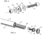
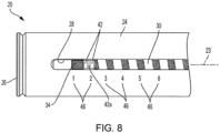
- FIG. 2-5 and 8 An embodiment of a door closer or operator including embodiments of the spring adjuster and indicator of the present invention are shown in Figs. 2-5 and 8 , inclusive.
- the spring adjuster and indicator 20 of the present invention can be used on any otherwise conventional door closer or operator that uses a linearly adjustable spring for applying the desired degree of force for closing the door, such as the door closer 120 of Fig. 1 .
- the spring in the door operator/closer indirectly applies force to the door in the closing direction.
- door closer or operator 22 is affixed to a door or a frame for the door (not shown), and has a dampening mechanism (not shown) that resists the force of the spring and controls the speed at which the door closes.
- the closer spring is pre-loaded so that it applies force on the dampening mechanism and door even when the door is closed, which degree of prestress must be overcome when the door is initially opened.
- the amount of spring force is determined by the geometry of the spring and its degree of compression, i.e., the amount of preload applied by compressing the spring from its static length.
- spring adjuster and indicator 20 includes a housing 24 in the form of an elongated tube and, inside, a compression coil spring 30 which applies the door-closing force to door operator/closer 22 at proximal end 48.
- a compression coil spring 30 which applies the door-closing force to door operator/closer 22 at proximal end 48.
- housing tube 24 is rigidly secured within door operator/closer 22 at proximal end 48 to the fixed door operator or closer to prevent rotation of the housing about longitudinal axis 23.
- An end cap 26 closes the distal end of tube 24, and includes an opening 27 permitting access for rotation of a nut threaded onto an adjustment screw for adjusting the force of the spring, while the housing remains stationary, as will be discussed in more detail below.
- an adjustment screw 34 threaded along all or a portion of its length ( Figs. 3-4 ).
- a rod 70 may be engagable with the head 38 of the adjustment screw 34 and the rod may be affixed at the proximal end 48 of the housing 24 so that the adjustment screw is stabilized along the central axis 23 and is prevented from moving in an axial direction.
- a spring collar 40 is slidable along longitudinal axis 23 so that the adjustment screw passes through the spring collar, and bears against the distal end 30a of spring 30 ( Figs. 3-5 ).
- the tube 24, collar 40 and adjustment screw 34 are restricted from relative rotational movement.
- the spring adjuster 20 of the present invention includes a nut 50 threaded on the adjustment screw 34.
- the force on the spring 30 is adjusted by rotating the nut 50 by hand or by tool, such as with a socket.
- Nut 50 bears against spring collar 40 such that rotating the nut 50 serves to move the spring collar 40 longitudinally in the direction of arrow 31 to adjust the degree of compression and therefore the preload of the spring 30.
- Spring collar 40 lacks internal threads and is adapted to slide on the adjustment screw 34 for preload on the spring when tightening, but hold the adjustment screw 34 rigid about the longitudinal axis 23, preventing rotation.
- a Double-D shape spring collar as shown may be used, wherein the straight internal sides 44a, 44b of the collar opening are adapted to slide along flat sections 36 on either side of the adjusting screw 34 ( Fig. 4 ).
- washers 54a, 54b may be used on either side of the collar 40 so that a plastic collar part may be used, however it should be understood by those skilled in the art that in other embodiments, spring collar 40 could also be made as one single, unitary part.
- the selected degree of compression of the spring operates to vary the force applied by the door operator or closer, with a shorter extension (i.e., greater compression) applying more force, and a longer extension (i.e., less compression) applying less force.
- the spring collar 40 includes a tab 42 extending radially outward from the collar, which collar tab is received within and slidable in a slot or window 28 extending along a length of and through the side wall of tube 24 ( Figs. 2 , 4 and 5 ).
- the tab/slot interface is designed to permit the spring collar 40 to move longitudinally to adjust the degree of compression and therefore the preload of the spring 30, while preventing rotation of the spring collar about the tube longitudinal axis 23. It should be understood by those skilled in the art that the Double-D shape spring collar 40 with tab 42 shown herein is only one such means for achieving the desired longitudinal (and not rotational) movement, and that other known methods are contemplated by the present invention, within the scope of the claims.
- spring collar tab 42 may have a mark 42a thereon, which is indexable along markings or indicia 46, for example numerals 1-6, adjacent the slot and extending along the length of the tube exterior.
- markings or indicia 46 for example numerals 1-6
- Figs. 6 and 7 depict a spring adjuster and housing not according to the invention, wherein the spring collar and housing also have matching cross-sections and clearances to prevent rotation of the spring collar about the longitudinal axis of the housing.
- spring collar 40' has a non-circular profile comprising a plurality of spaced protrusions 41 about its perimeter.
- Fig. 6 and best seen in Fig.
- housing 24 has a complementary non-circular cross-section comprising a plurality of depressions 25 which mate with the protrusions 41 of collar 40', forming a series of alternating protrusions and depressions which prohibit rotation of collar 40' about the longitudinal axis 23 of housing 24, but permit linear movement of collar 40' within the housing, during rotation of nut 50 to adjust the spring force.
- Adjustment screw 34 extends through spring collar 40' and collar 40' is adapted to slide along the length of the adjustment screw 34 for preload on the spring when tightening, but hold the adjustment screw 34 rigid about the longitudinal axis 23, preventing rotation, as in the embodiment of Figs. 2-5 .
- Spring collar 40' has an opening comprising straight internal sides 44a', 44b' which are adapted to slide along flat sections 36 on eitherside of the adjusting screw 34 ( Fig. 6 ).
- the position of spring 30 and spring collar 40' linearly along axis 23 may be visible through slot opening 28 in housing 24 to indicate the spring setting of the closer and the preload of the spring on the closer. It should be understood by those skilled in the art that other non-circular complementary cross-sections may also be used to prohibit rotation of the spring collar about the longitudinal axis of the housing, while permitting linear movement of the spring collar within the housing, within the scope of the claims.
- an installer rotates nut 50 about the longitudinal axis of adjustment screw 34 by hand or by using a tool such as a socket, in a clockwise or counterclockwise direction, which causes spring collar 40 or 40' to slidably move along the length of screw 34 and tab 42 to slide linearly along the length of slot 28 within stationary housing 24.
- the spring collar moves linearly along axis 23
- the spring either compresses or relaxes, thus changing the preload of the spring to increase or decrease the force on the door operator/closer.
- the compression of the spring can be seen through the window 28 in the tube and provides a visual indicator of the closer setting, based on spring force.
- the position of the spring collar which may be converted to and indicates the amount of force applied by spring 30, is indicated by the position of tab mark 42a and indicia 46 marked on the tube. This enables the user or installer to easily see the setting to which the door operator/closer is adjusted or set. Moreover, the compression of the spring may easily be re-adjusted after installation by way of the opening 27 in end cap 26 which permits access for rotation of the nut 50 by hand or by tool, without removing the closer housing 24.
- the adjusting screw of the present invention does not turn during adjustment of the spring tension and, instead, the spring tension is adjusted by rotating a nut clockwise or counterclockwise which causes the spring collar to slidably move along the length of the adjustment screw to increase or decrease the spring force.
- the spring collar is non-rotatable about the longitudinal axis of the housing, and may be fixed in the slot of the tube, therefore as the nut is rotated, the spring collar moves linearly in the slot while the adjusting screw does not rotate, thus changing the preload of the spring.
- the compression of the spring may be seen through a slot or window extending along the length of the spring tube.
Landscapes
- Closing And Opening Devices For Wings, And Checks For Wings (AREA)
- Casings For Electric Apparatus (AREA)
- Springs (AREA)
Claims (14)
- Vorrichtung zum Einstellen der Kraft in einem Türbetätiger oder -schließer (22) zum Schließen einer Tür, die Folgendes umfasst:ein Gehäuse (24) mit einer Längsachse (23) und einer Seitenwand mit einem Schlitz (28), der sich mindestens über einen Teil seiner Länge erstreckt;eine Feder (30) innerhalb des Gehäuses, die mit dem Türbetätiger oder -schließer (22) verbunden ist, wobei die Feder in verschiedene Positionen komprimierbar ist, um die von dem Türbetätiger oder -schließer ausgeübte Kraft zu verändern; undeinen Federteller (40, 40'), der nicht um die Längsachse des Gehäuses drehbar und zum linearen Bewegen innerhalb des Gehäuses ausgelegt ist, wobei der Federteller einen Ansatz (42) einschließt, der innerhalb des Gehäuseschlitzes (28) aufgenommen ist und darin gleiten kann, um eine Drehung des Federtellers um die Längsachse des Gehäuses zu verhindern, wobei der Federteller auf der Feder aufliegt, um die Federkompression und dadurch die vom Türbetätiger oder -schließer ausgeübte Kraft zu variieren, wobei der Federtelleransatz (42) mindestens teilweise von der Außenseite des Gehäuses durch den Seitenwandschlitz (28) sichtbar ist, um die Kompression der Feder anzuzeigen;gekennzeichnet durch:eine Einstellschraube (34), die sich entlang der Längsachse des Gehäuses erstreckt und durch den Federteller (40, 40') verläuft, undeine Mutter (50), die an einem Ende der Einstellschraube distal von dem Türbetätiger oder -schließer in Gewindeeingriff und um die Längsachse drehbar ist, wobei die Mutter während der Drehung auf dem Federteller aufliegt,wobei die Einstellschraube (34) einen nicht kreisförmigen Querschnitt hat und der Federteller (40. 40') eine Öffnung mit einem komplementär geformten, nicht kreisförmigen Querschnitt umfasst, um eine gleitende Linearbewegung des Federtellers entlang einer Außenfläche der Einstellschraube während der Drehung der Mutter zuzulassen, während eine Drehung der Einstellschraube um die Längsachse (23) des Gehäuses verhindert wird.
- Vorrichtung nach Anspruch 1, wobei die Außenfläche der Einstellschraube (34) gegenüberliegende flache Sektionen (36) umfasst und der Federteller (40, 40') eine Öffnung mit flachen Innenseiten (44a, 44b, 44a', 44b') zum Verpaaren mit den flachen Sektionen der Einstellschraube umfasst.
- Vorrichtung nach Anspruch 1 oder 2, die ferner eine Endkappe (26) an einem distalen Ende des Gehäuses einschließt, wobei die Endkappe eine Öffnung (27) umfasst, die den Zugang zum Drehen der Mutter ermöglicht.
- Vorrichtung nach Anspruch 1, 2 oder 3, die ferner eine oder mehrere den Grad der Federkompression anzeigende Markierungen (46) auf dem Gehäuse einschließt.
- Vorrichtung nach Anspruch 1, wobei die Feder ein Ende (30a) distal vom Türbetätiger oder -schließer hat und der Federteller (40, 40') am Federende anliegt.
- Vorrichtung nach Anspruch 1, wobei der Federteller (40, 40') und das Gehäuse (24) komplementär geformte, nicht kreisförmige Querschnitte haben, um eine Drehung des Federtellers um die Längsachse (23) des Gehäuses zu verhindern und gleichzeitig eine Linearbewegung des Federtellers innerhalb des Gehäuses zuzulassen.
- Vorrichtung nach Anspruch 6, wobei der Federteller (40, 40') eine Vielzahl von beabstandeten Vorsprüngen (41) um seinen Umfang herum umfasst und eine Innenfläche des Gehäuses eine Vielzahl von beabstandeten Vertiefungen (25) umfasst, die sich mit den Federtellervorsprüngen verpaaren.
- Verfahren zum Einstellen der Kraft in einem Türbetätiger oder -schließer (22) zum Schließen einer Tür, das Folgendes umfasst:Bereitstellen eines Gehäuses (24) mit einer Längsachse (23) und einer Seitenwand mit einem Schlitz (28), der sich mindestens über einen Teil seiner Länge erstreckt; eine Feder (30) innerhalb des Gehäuses, die mit dem Türbetätiger oder -schließer verbunden ist, einen Federteller (40, 40'), der nicht um die Längsachse des Gehäuses drehbar ist und zum linearen Bewegen innerhalb des Gehäuses ausgelegt ist, wobei der Federteller auf der Feder aufliegt und einen Ansatz (42) einschließt, der innerhalb des Gehäuseschlitzes aufgenommen wird und darin gleiten kann, wobei der Ansatz mindestens teilweise von der Außenseite des Gehäuses durch den Seitenwandschlitz sichtbar ist, um die Kompression der Feder anzuzeigen;gekennzeichnet durchferner Bereitstellen einer Einstellschraube (34), die sich entlang einer Längsachse des Gehäuses erstreckt und durch den Federteller (40, 40') verläuft, wobei die Einstellschraube (34) einen nicht kreisförmigen Querschnitt hat und der Federteller (40, 40') eine Öffnung mit einem komplementär geformten, nicht kreisförmigen Querschnitt umfasst, um eine gleitende Linearbewegung des Federtellers entlang einer Außenfläche der Einstellschraube während der Drehung der Mutter zuzulassen, während die Drehung der Einstellschraube um die Längsachse (23) des Gehäuses verhindert wird; undferner Bereitstellen einer Mutter (50), die an einem Ende (30a) der Einstellschraube distal von dem Türbetätiger oder -schließer in Gewindeeingriff und um die Längsachse drehbar ist, wobei die Mutter während der Drehung auf dem Federteller aufliegt,und das ferner die folgenden Schritte einschließt:Bewegen des Federtellers (40, 40') linear entlang der Längsachse des Gehäuses, um die Kompression der Feder (30) durch Drehen der Mutter (50) um eine Längsachse der Einstellschraube zu verändern, wodurch die von dem Türbetätiger oder -schließer aufgebrachte Kraft zum Schließen der Tür variiert wird; undBetrachten der Position des Federtelleransatzes (42) von der Außenseite des Gehäuses durch den Seitenwandschlitz (28), um die Position der Feder und die von der Feder auf den Türbetätiger oder -schließer ausgeübte Kraft zu bestimmen.
- Verfahren nach Anspruch 8, wobei die Mutter (50) im Uhrzeigersinn oder gegen den Uhrzeigersinn gedreht wird, um die Federkompression und die vom Türbetätiger oder
-schließer (22) aufgebrachte Kraft zu erhöhen oder zu verringern. - Verfahren nach Anspruch 8, wobei die Einstellschraube (34) durch den Federteller (40, 40') verläuft und der Federteller entlang einer Außenfläche der Einstellschraube verschiebbar ist, und wobei der Schritt des linearen Bewegens des Federtellers entlang der Längsachse (23) des Gehäuses Folgendes umfasst:
Drehen der Mutter (50) um die Längsachse der Einstellschraube, um zu bewirken, dass der Federteller entlang der Außenfläche der Einstellschraube zu einer gewünschten Position gleitet, um die gewünschte Kraft auf den Türbetätiger oder -schließer auszuüben, wobei der Federteller eine Drehung der Einstellschraube um die Längsachse des Gehäuses verhindert. - Verfahren nach Anspruch 8, wobei das Gehäuse eine Endkappe (26) an einem distalen Ende des Gehäuses einschließt, die eine Öffnung (27) umfasst, die den Zugang zum Drehen der Mutter ermöglicht, und wobei der Schritt des linearen Bewegens des Federtellers entlang der Längsachse des Gehäuses den Zugang zur Mutter durch die Endkappenöffnung und das Drehen der Mutter um die Längsachse der Einstellschraube umfasst, während das Gehäuse stationär bleibt.
- Verfahren nach Anspruch 8, das ferner den Schritt des Verhinderns der Drehung der Einstellschraube (34) um die Längsachse des Gehäuses während der Drehung der Mutter (50) einschließt.
- Verfahren nach Anspruch 8, wobei das Gehäuse eine oder mehrere den Grad der Federkompression anzeigende Markierungen (46) auf einer Außenfläche davon einschließt, und das ferner den folgenden Schritt einschließt:
Bestimmen des Grades an Federkompression anhand der ein oder mehreren Markierungen auf dem Gehäuse. - Verfahren nach Anspruch 8, das ferner die folgenden Schritte einschließt:Bereitstellen eines Indikators (42a), der entlang des Gehäuses beweglich und von der Außenseite des Gehäuses sichtbar ist, um die Kompression der Feder anzuzeigen, wobei eine Position des Indikators von der Außenseite des Gehäuses durch den Seitenwandschlitz sichtbar ist, undBetrachten der Position des Indikators von der Außenseite des Gehäuses durch den Seitenwandschlitz, um den Grad der Federkompression zu bestimmen.
Applications Claiming Priority (3)
| Application Number | Priority Date | Filing Date | Title |
|---|---|---|---|
| US201562237724P | 2015-10-06 | 2015-10-06 | |
| US15/280,014 US10180023B2 (en) | 2015-10-06 | 2016-09-29 | Apparatus and method for control of spring force in a door closer or operator |
| PCT/US2016/054835 WO2017062283A1 (en) | 2015-10-06 | 2016-09-30 | Apparatus and method for control of spring force in a door closer or operator |
Publications (3)
| Publication Number | Publication Date |
|---|---|
| EP3359767A1 EP3359767A1 (de) | 2018-08-15 |
| EP3359767A4 EP3359767A4 (de) | 2018-10-31 |
| EP3359767B1 true EP3359767B1 (de) | 2023-10-25 |
Family
ID=58447305
Family Applications (1)
| Application Number | Title | Priority Date | Filing Date |
|---|---|---|---|
| EP16854120.9A Active EP3359767B1 (de) | 2015-10-06 | 2016-09-30 | Vorrichtung und verfahren zur steuerung der federkraft bei einem türschliesser oder -bediener |
Country Status (7)
| Country | Link |
|---|---|
| US (1) | US10180023B2 (de) |
| EP (1) | EP3359767B1 (de) |
| AU (1) | AU2016335942A1 (de) |
| CA (1) | CA3000223C (de) |
| MX (1) | MX2018004106A (de) |
| TW (1) | TW201723296A (de) |
| WO (1) | WO2017062283A1 (de) |
Families Citing this family (25)
| Publication number | Priority date | Publication date | Assignee | Title |
|---|---|---|---|---|
| US10914412B2 (en) | 2018-06-28 | 2021-02-09 | Watts Regulator Co. | Backflow prevention assembly having a variable lay-length and orientation |
| CN108843202B (zh) * | 2018-08-02 | 2023-07-28 | 无锡爱一力机械有限公司 | 一种可调节旋转自闭安全门 |
| US10982479B2 (en) * | 2019-04-30 | 2021-04-20 | Schlage Lock Company Llc | Door closer adjustment mechanism |
| US11795666B2 (en) | 2019-05-08 | 2023-10-24 | Watts Regulator Co. | Wireless communication system within a mechanical room |
| US12195954B2 (en) | 2019-12-10 | 2025-01-14 | Watts Regulator Co. | System for monitoring backflow preventer condition |
| AT523797A1 (de) * | 2020-04-20 | 2021-11-15 | Blum Gmbh Julius | Möbelantrieb zum Bewegen eines relativ zu einem Möbelkorpus bewegbar gelagerten Möbelteiles |
| CN111520016A (zh) * | 2020-05-14 | 2020-08-11 | 湖南铁道职业技术学院天一实业有限公司 | 一种机车闭门器及弹簧压力调节结构的加工组装方法 |
| US11719352B2 (en) | 2020-08-17 | 2023-08-08 | Watts Regulator Co. | Check cover assemblies for backflow prevention assemblies with integrated test cock protection shroud |
| TWI769855B (zh) | 2021-06-11 | 2022-07-01 | 一德金屬工業股份有限公司 | 利用即時無線供電的鎖具的解鎖方法 |
| TWI802033B (zh) | 2021-10-06 | 2023-05-11 | 一德金屬工業股份有限公司 | 簡易安裝的門弓器 |
| TWI776725B (zh) | 2021-11-03 | 2022-09-01 | 一德金屬工業股份有限公司 | 門弓器 |
| TWI810821B (zh) | 2022-02-18 | 2023-08-01 | 一德金屬工業股份有限公司 | 具有離合器的鎖具 |
| TWI789280B (zh) | 2022-03-28 | 2023-01-01 | 一德金屬工業股份有限公司 | 簡便拆裝輸入介面電子模組的門鎖 |
| US12116825B2 (en) * | 2022-04-13 | 2024-10-15 | Schlage Lock Company Llc | Adjustment screw indicator mechanism |
| TWI790170B (zh) | 2022-05-23 | 2023-01-11 | 一德金屬工業股份有限公司 | 可電動上鎖與解鎖的門鎖 |
| TWI815529B (zh) | 2022-06-29 | 2023-09-11 | 一德金屬工業股份有限公司 | 電動控制門鎖 |
| TWI828293B (zh) | 2022-08-31 | 2024-01-01 | 一德金屬工業股份有限公司 | 能控制關門速度的門弓器 |
| TWI828294B (zh) | 2022-08-31 | 2024-01-01 | 一德金屬工業股份有限公司 | 具有防鬆脫連桿組的門弓器 |
| TWI798156B (zh) | 2022-09-23 | 2023-04-01 | 一德金屬工業股份有限公司 | 具防撬功能的鎖匣 |
| TWI821011B (zh) | 2022-11-10 | 2023-11-01 | 一德金屬工業股份有限公司 | 可連動防盜閂的鎖匣 |
| TWI815753B (zh) | 2022-12-19 | 2023-09-11 | 一德金屬工業股份有限公司 | 重型鎖匣 |
| TWI885339B (zh) | 2023-03-07 | 2025-06-01 | 一德金屬工業股份有限公司 | 密碼式鎖具的管控方法 |
| TWI854632B (zh) | 2023-05-04 | 2024-09-01 | 一德金屬工業股份有限公司 | 可緊急通報的門禁管制方法 |
| TWI880445B (zh) | 2023-11-10 | 2025-04-11 | 一德金屬工業股份有限公司 | 發生槍擊事件時的各人員定位與追蹤方法 |
| TWI891328B (zh) | 2024-04-18 | 2025-07-21 | 一德金屬工業股份有限公司 | 適用車輛的門禁管制方法 |
Family Cites Families (19)
| Publication number | Priority date | Publication date | Assignee | Title |
|---|---|---|---|---|
| US2414894A (en) * | 1945-01-15 | 1947-01-28 | Pfent Frank | Door controller |
| GB1272405A (en) * | 1969-07-23 | 1972-04-26 | Henry Alfred Farrow | Biassing device for hinged doors, gates or the like |
| DE3224300C2 (de) * | 1982-06-29 | 1984-11-29 | Geze Gmbh, 7250 Leonberg | Türschließer mit einstellbarer Schließkraft |
| GB8522565D0 (en) | 1985-09-12 | 1985-10-16 | Newman Tonks Eng Ltd | Door closer |
| US4783882A (en) | 1986-01-13 | 1988-11-15 | Emhart Industries, Inc. | Door closer assembly |
| DE4038259A1 (de) | 1989-12-21 | 1991-06-27 | Anthony S Mfg Co | Scharnieranordnung fuer selbstschliessende tueren |
| US5265306A (en) * | 1993-01-15 | 1993-11-30 | Yu King Sung | Automatic door closing device |
| US5636678A (en) | 1994-06-16 | 1997-06-10 | Clopay Building Products Company, Inc. | Counterbalancing mechanism for an overhead door |
| DE19506220C2 (de) | 1995-02-22 | 1996-12-12 | Dorma Gmbh & Co Kg | Türschließer |
| US6282750B1 (en) | 1999-10-15 | 2001-09-04 | Ingersoll-Rand Architectural Hardware Group Limited | Power adjustment size indicator for a door closer |
| US6711856B1 (en) * | 2002-09-19 | 2004-03-30 | Drew Hoffman | Door opener assist device |
| TWI243878B (en) | 2004-05-19 | 2005-11-21 | Jeng-Ming Jou | An adjusting method and adjusting mechanism for remedying the coil pitch tolerance and fatigue deformation of adjustable helical spring |
| FR2904651B1 (fr) | 2006-08-07 | 2010-10-15 | Somfy Sas | Dispositif d'entrainement d'un element mobile d'un batiment par l'intermediaire d'un lien souple |
| US8732905B2 (en) * | 2010-02-11 | 2014-05-27 | Yale Security Inc. | Door or window closer |
| AT514585B1 (de) * | 2013-08-30 | 2015-02-15 | Blum Gmbh Julius | Stellantrieb für bewegbare Möbelteile |
| WO2015077628A1 (en) * | 2013-11-21 | 2015-05-28 | Stabilus, Inc. | Systems and methods for piston assemblies |
| US20150176319A1 (en) * | 2013-12-20 | 2015-06-25 | Shen-Fu Huang | Cam-type oil-free automatic door closer |
| AT515492B1 (de) * | 2014-03-14 | 2020-01-15 | Blum Gmbh Julius | Stellantrieb für Möbelklappen |
| US9695620B2 (en) * | 2014-10-02 | 2017-07-04 | Yale Security Inc. | Apparatus and method for rotating tube adjustment and visually indicating spring force in a door operator or closer |
-
2016
- 2016-09-29 US US15/280,014 patent/US10180023B2/en active Active
- 2016-09-30 AU AU2016335942A patent/AU2016335942A1/en not_active Abandoned
- 2016-09-30 EP EP16854120.9A patent/EP3359767B1/de active Active
- 2016-09-30 WO PCT/US2016/054835 patent/WO2017062283A1/en not_active Ceased
- 2016-09-30 MX MX2018004106A patent/MX2018004106A/es unknown
- 2016-09-30 CA CA3000223A patent/CA3000223C/en active Active
- 2016-10-05 TW TW105132196A patent/TW201723296A/zh unknown
Also Published As
| Publication number | Publication date |
|---|---|
| EP3359767A1 (de) | 2018-08-15 |
| US10180023B2 (en) | 2019-01-15 |
| AU2016335942A1 (en) | 2018-04-19 |
| MX2018004106A (es) | 2019-04-29 |
| CA3000223A1 (en) | 2017-04-13 |
| WO2017062283A1 (en) | 2017-04-13 |
| CA3000223C (en) | 2021-11-16 |
| EP3359767A4 (de) | 2018-10-31 |
| TW201723296A (zh) | 2017-07-01 |
| US20170096848A1 (en) | 2017-04-06 |
Similar Documents
| Publication | Publication Date | Title |
|---|---|---|
| EP3359767B1 (de) | Vorrichtung und verfahren zur steuerung der federkraft bei einem türschliesser oder -bediener | |
| US9695620B2 (en) | Apparatus and method for rotating tube adjustment and visually indicating spring force in a door operator or closer | |
| US8281677B2 (en) | Electromotive linear drive | |
| CA2320662C (en) | Power adjustment size indicator for a door closer | |
| CN105064847A (zh) | 门驱动装置 | |
| US20060131111A1 (en) | Braking apparatus for closure members | |
| RU2007145198A (ru) | Конечное устройство перемещения для систем привода рольставней или светозащитных навесов | |
| US20090223313A1 (en) | Drive apparatus for a swing-out element of a motor vehicle | |
| US3675371A (en) | Spring closeable window operating mechanism | |
| US20100006389A1 (en) | Sprung anti-backing-off device | |
| EP2186983A1 (de) | Bidirektionaler Schließmechanismus | |
| AU2016238980B2 (en) | Adjustable Operator Worm Gear Drive with Robust Bearing Surfaces | |
| CA2907238C (en) | Apparatus and method for rotating tube adjustment and visually indicating spring force in a door operator or closer | |
| US3911527A (en) | Spring adjustment mechanism | |
| EP3521537A2 (de) | Griff | |
| EP1614851B1 (de) | Endabschaltung für einen Rolladenantrieb | |
| EP2524098B1 (de) | Verbesserungen in dämpfungsvorrichtungen | |
| AU2010201439A1 (en) | Gate operator | |
| US5111925A (en) | Device for automatically halting an electric motor after a certain number of revolutions | |
| EP2185782B1 (de) | Antriebsarm | |
| AU2010201579A1 (en) | Gate Operator Datum Setting | |
| EP2469000A1 (de) | Vorrichtung zum manuellen Bewegen von Läden, Türen und dergleichen | |
| IT1271225B (it) | Dispositivo di attuazione pneumatico per elementi valvolari e simili | |
| HK1217037B (en) | Door drive |
Legal Events
| Date | Code | Title | Description |
|---|---|---|---|
| STAA | Information on the status of an ep patent application or granted ep patent |
Free format text: STATUS: THE INTERNATIONAL PUBLICATION HAS BEEN MADE |
|
| PUAI | Public reference made under article 153(3) epc to a published international application that has entered the european phase |
Free format text: ORIGINAL CODE: 0009012 |
|
| STAA | Information on the status of an ep patent application or granted ep patent |
Free format text: STATUS: REQUEST FOR EXAMINATION WAS MADE |
|
| 17P | Request for examination filed |
Effective date: 20180405 |
|
| AK | Designated contracting states |
Kind code of ref document: A1 Designated state(s): AL AT BE BG CH CY CZ DE DK EE ES FI FR GB GR HR HU IE IS IT LI LT LU LV MC MK MT NL NO PL PT RO RS SE SI SK SM TR |
|
| AX | Request for extension of the european patent |
Extension state: BA ME |
|
| A4 | Supplementary search report drawn up and despatched |
Effective date: 20181004 |
|
| RIC1 | Information provided on ipc code assigned before grant |
Ipc: E05F 1/10 20060101ALI20180927BHEP Ipc: E05F 3/00 20060101ALI20180927BHEP Ipc: E05F 3/10 20060101AFI20180927BHEP Ipc: E05F 3/22 20060101ALI20180927BHEP |
|
| DAV | Request for validation of the european patent (deleted) | ||
| DAX | Request for extension of the european patent (deleted) | ||
| STAA | Information on the status of an ep patent application or granted ep patent |
Free format text: STATUS: EXAMINATION IS IN PROGRESS |
|
| 17Q | First examination report despatched |
Effective date: 20201216 |
|
| GRAP | Despatch of communication of intention to grant a patent |
Free format text: ORIGINAL CODE: EPIDOSNIGR1 |
|
| STAA | Information on the status of an ep patent application or granted ep patent |
Free format text: STATUS: GRANT OF PATENT IS INTENDED |
|
| INTG | Intention to grant announced |
Effective date: 20221031 |
|
| GRAJ | Information related to disapproval of communication of intention to grant by the applicant or resumption of examination proceedings by the epo deleted |
Free format text: ORIGINAL CODE: EPIDOSDIGR1 |
|
| STAA | Information on the status of an ep patent application or granted ep patent |
Free format text: STATUS: EXAMINATION IS IN PROGRESS |
|
| INTC | Intention to grant announced (deleted) | ||
| GRAP | Despatch of communication of intention to grant a patent |
Free format text: ORIGINAL CODE: EPIDOSNIGR1 |
|
| STAA | Information on the status of an ep patent application or granted ep patent |
Free format text: STATUS: GRANT OF PATENT IS INTENDED |
|
| INTG | Intention to grant announced |
Effective date: 20230508 |
|
| P01 | Opt-out of the competence of the unified patent court (upc) registered |
Effective date: 20230517 |
|
| GRAS | Grant fee paid |
Free format text: ORIGINAL CODE: EPIDOSNIGR3 |
|
| GRAA | (expected) grant |
Free format text: ORIGINAL CODE: 0009210 |
|
| STAA | Information on the status of an ep patent application or granted ep patent |
Free format text: STATUS: THE PATENT HAS BEEN GRANTED |
|
| AK | Designated contracting states |
Kind code of ref document: B1 Designated state(s): AL AT BE BG CH CY CZ DE DK EE ES FI FR GB GR HR HU IE IS IT LI LT LU LV MC MK MT NL NO PL PT RO RS SE SI SK SM TR |
|
| REG | Reference to a national code |
Ref country code: GB Ref legal event code: FG4D |
|
| REG | Reference to a national code |
Ref country code: CH Ref legal event code: EP |
|
| REG | Reference to a national code |
Ref country code: DE Ref legal event code: R096 Ref document number: 602016083732 Country of ref document: DE |
|
| REG | Reference to a national code |
Ref country code: IE Ref legal event code: FG4D |
|
| REG | Reference to a national code |
Ref country code: LT Ref legal event code: MG9D |
|
| REG | Reference to a national code |
Ref country code: NL Ref legal event code: MP Effective date: 20231025 |
|
| REG | Reference to a national code |
Ref country code: AT Ref legal event code: MK05 Ref document number: 1624818 Country of ref document: AT Kind code of ref document: T Effective date: 20231025 |
|
| PG25 | Lapsed in a contracting state [announced via postgrant information from national office to epo] |
Ref country code: NL Free format text: LAPSE BECAUSE OF FAILURE TO SUBMIT A TRANSLATION OF THE DESCRIPTION OR TO PAY THE FEE WITHIN THE PRESCRIBED TIME-LIMIT Effective date: 20231025 |
|
| PG25 | Lapsed in a contracting state [announced via postgrant information from national office to epo] |
Ref country code: GR Free format text: LAPSE BECAUSE OF FAILURE TO SUBMIT A TRANSLATION OF THE DESCRIPTION OR TO PAY THE FEE WITHIN THE PRESCRIBED TIME-LIMIT Effective date: 20240126 |
|
| PG25 | Lapsed in a contracting state [announced via postgrant information from national office to epo] |
Ref country code: IS Free format text: LAPSE BECAUSE OF FAILURE TO SUBMIT A TRANSLATION OF THE DESCRIPTION OR TO PAY THE FEE WITHIN THE PRESCRIBED TIME-LIMIT Effective date: 20240225 |
|
| PG25 | Lapsed in a contracting state [announced via postgrant information from national office to epo] |
Ref country code: LT Free format text: LAPSE BECAUSE OF FAILURE TO SUBMIT A TRANSLATION OF THE DESCRIPTION OR TO PAY THE FEE WITHIN THE PRESCRIBED TIME-LIMIT Effective date: 20231025 |
|
| PG25 | Lapsed in a contracting state [announced via postgrant information from national office to epo] |
Ref country code: AT Free format text: LAPSE BECAUSE OF FAILURE TO SUBMIT A TRANSLATION OF THE DESCRIPTION OR TO PAY THE FEE WITHIN THE PRESCRIBED TIME-LIMIT Effective date: 20231025 |
|
| PG25 | Lapsed in a contracting state [announced via postgrant information from national office to epo] |
Ref country code: ES Free format text: LAPSE BECAUSE OF FAILURE TO SUBMIT A TRANSLATION OF THE DESCRIPTION OR TO PAY THE FEE WITHIN THE PRESCRIBED TIME-LIMIT Effective date: 20231025 |
|
| PG25 | Lapsed in a contracting state [announced via postgrant information from national office to epo] |
Ref country code: LT Free format text: LAPSE BECAUSE OF FAILURE TO SUBMIT A TRANSLATION OF THE DESCRIPTION OR TO PAY THE FEE WITHIN THE PRESCRIBED TIME-LIMIT Effective date: 20231025 Ref country code: IS Free format text: LAPSE BECAUSE OF FAILURE TO SUBMIT A TRANSLATION OF THE DESCRIPTION OR TO PAY THE FEE WITHIN THE PRESCRIBED TIME-LIMIT Effective date: 20240225 Ref country code: GR Free format text: LAPSE BECAUSE OF FAILURE TO SUBMIT A TRANSLATION OF THE DESCRIPTION OR TO PAY THE FEE WITHIN THE PRESCRIBED TIME-LIMIT Effective date: 20240126 Ref country code: ES Free format text: LAPSE BECAUSE OF FAILURE TO SUBMIT A TRANSLATION OF THE DESCRIPTION OR TO PAY THE FEE WITHIN THE PRESCRIBED TIME-LIMIT Effective date: 20231025 Ref country code: BG Free format text: LAPSE BECAUSE OF FAILURE TO SUBMIT A TRANSLATION OF THE DESCRIPTION OR TO PAY THE FEE WITHIN THE PRESCRIBED TIME-LIMIT Effective date: 20240125 Ref country code: AT Free format text: LAPSE BECAUSE OF FAILURE TO SUBMIT A TRANSLATION OF THE DESCRIPTION OR TO PAY THE FEE WITHIN THE PRESCRIBED TIME-LIMIT Effective date: 20231025 Ref country code: PT Free format text: LAPSE BECAUSE OF FAILURE TO SUBMIT A TRANSLATION OF THE DESCRIPTION OR TO PAY THE FEE WITHIN THE PRESCRIBED TIME-LIMIT Effective date: 20240226 |
|
| PG25 | Lapsed in a contracting state [announced via postgrant information from national office to epo] |
Ref country code: SE Free format text: LAPSE BECAUSE OF FAILURE TO SUBMIT A TRANSLATION OF THE DESCRIPTION OR TO PAY THE FEE WITHIN THE PRESCRIBED TIME-LIMIT Effective date: 20231025 Ref country code: RS Free format text: LAPSE BECAUSE OF FAILURE TO SUBMIT A TRANSLATION OF THE DESCRIPTION OR TO PAY THE FEE WITHIN THE PRESCRIBED TIME-LIMIT Effective date: 20231025 Ref country code: PL Free format text: LAPSE BECAUSE OF FAILURE TO SUBMIT A TRANSLATION OF THE DESCRIPTION OR TO PAY THE FEE WITHIN THE PRESCRIBED TIME-LIMIT Effective date: 20231025 Ref country code: NO Free format text: LAPSE BECAUSE OF FAILURE TO SUBMIT A TRANSLATION OF THE DESCRIPTION OR TO PAY THE FEE WITHIN THE PRESCRIBED TIME-LIMIT Effective date: 20240125 Ref country code: LV Free format text: LAPSE BECAUSE OF FAILURE TO SUBMIT A TRANSLATION OF THE DESCRIPTION OR TO PAY THE FEE WITHIN THE PRESCRIBED TIME-LIMIT Effective date: 20231025 Ref country code: HR Free format text: LAPSE BECAUSE OF FAILURE TO SUBMIT A TRANSLATION OF THE DESCRIPTION OR TO PAY THE FEE WITHIN THE PRESCRIBED TIME-LIMIT Effective date: 20231025 |
|
| PG25 | Lapsed in a contracting state [announced via postgrant information from national office to epo] |
Ref country code: DK Free format text: LAPSE BECAUSE OF FAILURE TO SUBMIT A TRANSLATION OF THE DESCRIPTION OR TO PAY THE FEE WITHIN THE PRESCRIBED TIME-LIMIT Effective date: 20231025 |
|
| PG25 | Lapsed in a contracting state [announced via postgrant information from national office to epo] |
Ref country code: CZ Free format text: LAPSE BECAUSE OF FAILURE TO SUBMIT A TRANSLATION OF THE DESCRIPTION OR TO PAY THE FEE WITHIN THE PRESCRIBED TIME-LIMIT Effective date: 20231025 |
|
| REG | Reference to a national code |
Ref country code: DE Ref legal event code: R097 Ref document number: 602016083732 Country of ref document: DE |
|
| PG25 | Lapsed in a contracting state [announced via postgrant information from national office to epo] |
Ref country code: SK Free format text: LAPSE BECAUSE OF FAILURE TO SUBMIT A TRANSLATION OF THE DESCRIPTION OR TO PAY THE FEE WITHIN THE PRESCRIBED TIME-LIMIT Effective date: 20231025 |
|
| PG25 | Lapsed in a contracting state [announced via postgrant information from national office to epo] |
Ref country code: SM Free format text: LAPSE BECAUSE OF FAILURE TO SUBMIT A TRANSLATION OF THE DESCRIPTION OR TO PAY THE FEE WITHIN THE PRESCRIBED TIME-LIMIT Effective date: 20231025 Ref country code: SK Free format text: LAPSE BECAUSE OF FAILURE TO SUBMIT A TRANSLATION OF THE DESCRIPTION OR TO PAY THE FEE WITHIN THE PRESCRIBED TIME-LIMIT Effective date: 20231025 Ref country code: RO Free format text: LAPSE BECAUSE OF FAILURE TO SUBMIT A TRANSLATION OF THE DESCRIPTION OR TO PAY THE FEE WITHIN THE PRESCRIBED TIME-LIMIT Effective date: 20231025 Ref country code: IT Free format text: LAPSE BECAUSE OF FAILURE TO SUBMIT A TRANSLATION OF THE DESCRIPTION OR TO PAY THE FEE WITHIN THE PRESCRIBED TIME-LIMIT Effective date: 20231025 Ref country code: EE Free format text: LAPSE BECAUSE OF FAILURE TO SUBMIT A TRANSLATION OF THE DESCRIPTION OR TO PAY THE FEE WITHIN THE PRESCRIBED TIME-LIMIT Effective date: 20231025 Ref country code: DK Free format text: LAPSE BECAUSE OF FAILURE TO SUBMIT A TRANSLATION OF THE DESCRIPTION OR TO PAY THE FEE WITHIN THE PRESCRIBED TIME-LIMIT Effective date: 20231025 Ref country code: CZ Free format text: LAPSE BECAUSE OF FAILURE TO SUBMIT A TRANSLATION OF THE DESCRIPTION OR TO PAY THE FEE WITHIN THE PRESCRIBED TIME-LIMIT Effective date: 20231025 |
|
| PLBE | No opposition filed within time limit |
Free format text: ORIGINAL CODE: 0009261 |
|
| STAA | Information on the status of an ep patent application or granted ep patent |
Free format text: STATUS: NO OPPOSITION FILED WITHIN TIME LIMIT |
|
| 26N | No opposition filed |
Effective date: 20240726 |
|
| PG25 | Lapsed in a contracting state [announced via postgrant information from national office to epo] |
Ref country code: SI Free format text: LAPSE BECAUSE OF FAILURE TO SUBMIT A TRANSLATION OF THE DESCRIPTION OR TO PAY THE FEE WITHIN THE PRESCRIBED TIME-LIMIT Effective date: 20231025 |
|
| PG25 | Lapsed in a contracting state [announced via postgrant information from national office to epo] |
Ref country code: SI Free format text: LAPSE BECAUSE OF FAILURE TO SUBMIT A TRANSLATION OF THE DESCRIPTION OR TO PAY THE FEE WITHIN THE PRESCRIBED TIME-LIMIT Effective date: 20231025 |
|
| REG | Reference to a national code |
Ref country code: DE Ref legal event code: R119 Ref document number: 602016083732 Country of ref document: DE |
|
| PG25 | Lapsed in a contracting state [announced via postgrant information from national office to epo] |
Ref country code: MC Free format text: LAPSE BECAUSE OF FAILURE TO SUBMIT A TRANSLATION OF THE DESCRIPTION OR TO PAY THE FEE WITHIN THE PRESCRIBED TIME-LIMIT Effective date: 20231025 |
|
| REG | Reference to a national code |
Ref country code: CH Ref legal event code: PL |
|
| PG25 | Lapsed in a contracting state [announced via postgrant information from national office to epo] |
Ref country code: LU Free format text: LAPSE BECAUSE OF NON-PAYMENT OF DUE FEES Effective date: 20240930 |
|
| GBPC | Gb: european patent ceased through non-payment of renewal fee |
Effective date: 20240930 |
|
| PG25 | Lapsed in a contracting state [announced via postgrant information from national office to epo] |
Ref country code: DE Free format text: LAPSE BECAUSE OF NON-PAYMENT OF DUE FEES Effective date: 20250401 |
|
| PG25 | Lapsed in a contracting state [announced via postgrant information from national office to epo] |
Ref country code: GB Free format text: LAPSE BECAUSE OF NON-PAYMENT OF DUE FEES Effective date: 20240930 |
|
| REG | Reference to a national code |
Ref country code: BE Ref legal event code: MM Effective date: 20240930 |
|
| PG25 | Lapsed in a contracting state [announced via postgrant information from national office to epo] |
Ref country code: BE Free format text: LAPSE BECAUSE OF NON-PAYMENT OF DUE FEES Effective date: 20240930 |
|
| PG25 | Lapsed in a contracting state [announced via postgrant information from national office to epo] |
Ref country code: FR Free format text: LAPSE BECAUSE OF NON-PAYMENT OF DUE FEES Effective date: 20240930 |
|
| PG25 | Lapsed in a contracting state [announced via postgrant information from national office to epo] |
Ref country code: CH Free format text: LAPSE BECAUSE OF NON-PAYMENT OF DUE FEES Effective date: 20240930 |
|
| PG25 | Lapsed in a contracting state [announced via postgrant information from national office to epo] |
Ref country code: IE Free format text: LAPSE BECAUSE OF NON-PAYMENT OF DUE FEES Effective date: 20240930 |
|
| PG25 | Lapsed in a contracting state [announced via postgrant information from national office to epo] |
Ref country code: FI Free format text: LAPSE BECAUSE OF FAILURE TO SUBMIT A TRANSLATION OF THE DESCRIPTION OR TO PAY THE FEE WITHIN THE PRESCRIBED TIME-LIMIT Effective date: 20231025 |
|
| PG25 | Lapsed in a contracting state [announced via postgrant information from national office to epo] |
Ref country code: CY Free format text: LAPSE BECAUSE OF FAILURE TO SUBMIT A TRANSLATION OF THE DESCRIPTION OR TO PAY THE FEE WITHIN THE PRESCRIBED TIME-LIMIT; INVALID AB INITIO Effective date: 20160930 |
|
| PG25 | Lapsed in a contracting state [announced via postgrant information from national office to epo] |
Ref country code: HU Free format text: LAPSE BECAUSE OF FAILURE TO SUBMIT A TRANSLATION OF THE DESCRIPTION OR TO PAY THE FEE WITHIN THE PRESCRIBED TIME-LIMIT; INVALID AB INITIO Effective date: 20160930 |