EP3359801B1 - Agencement de détection de fuite - Google Patents
Agencement de détection de fuite Download PDFInfo
- Publication number
- EP3359801B1 EP3359801B1 EP15791000.1A EP15791000A EP3359801B1 EP 3359801 B1 EP3359801 B1 EP 3359801B1 EP 15791000 A EP15791000 A EP 15791000A EP 3359801 B1 EP3359801 B1 EP 3359801B1
- Authority
- EP
- European Patent Office
- Prior art keywords
- indicator element
- indicator
- leakage
- fuel
- retracted position
- Prior art date
- Legal status (The legal status is an assumption and is not a legal conclusion. Google has not performed a legal analysis and makes no representation as to the accuracy of the status listed.)
- Active
Links
Images
Classifications
-
- F—MECHANICAL ENGINEERING; LIGHTING; HEATING; WEAPONS; BLASTING
- F02—COMBUSTION ENGINES; HOT-GAS OR COMBUSTION-PRODUCT ENGINE PLANTS
- F02M—SUPPLYING COMBUSTION ENGINES IN GENERAL WITH COMBUSTIBLE MIXTURES OR CONSTITUENTS THEREOF
- F02M55/00—Fuel-injection apparatus characterised by their fuel conduits or their venting means; Arrangements of conduits between fuel tank and pump F02M37/00
- F02M55/002—Arrangement of leakage or drain conduits in or from injectors
-
- F—MECHANICAL ENGINEERING; LIGHTING; HEATING; WEAPONS; BLASTING
- F02—COMBUSTION ENGINES; HOT-GAS OR COMBUSTION-PRODUCT ENGINE PLANTS
- F02M—SUPPLYING COMBUSTION ENGINES IN GENERAL WITH COMBUSTIBLE MIXTURES OR CONSTITUENTS THEREOF
- F02M55/00—Fuel-injection apparatus characterised by their fuel conduits or their venting means; Arrangements of conduits between fuel tank and pump F02M37/00
- F02M55/004—Joints; Sealings
-
- F—MECHANICAL ENGINEERING; LIGHTING; HEATING; WEAPONS; BLASTING
- F02—COMBUSTION ENGINES; HOT-GAS OR COMBUSTION-PRODUCT ENGINE PLANTS
- F02M—SUPPLYING COMBUSTION ENGINES IN GENERAL WITH COMBUSTIBLE MIXTURES OR CONSTITUENTS THEREOF
- F02M55/00—Fuel-injection apparatus characterised by their fuel conduits or their venting means; Arrangements of conduits between fuel tank and pump F02M37/00
- F02M55/02—Conduits between injection pumps and injectors, e.g. conduits between pump and common-rail or conduits between common-rail and injectors
-
- F—MECHANICAL ENGINEERING; LIGHTING; HEATING; WEAPONS; BLASTING
- F02—COMBUSTION ENGINES; HOT-GAS OR COMBUSTION-PRODUCT ENGINE PLANTS
- F02M—SUPPLYING COMBUSTION ENGINES IN GENERAL WITH COMBUSTIBLE MIXTURES OR CONSTITUENTS THEREOF
- F02M65/00—Testing fuel-injection apparatus, e.g. testing injection timing ; Cleaning of fuel-injection apparatus
- F02M65/006—Measuring or detecting fuel leakage of fuel injection apparatus
Definitions
- the present invention relates to a leakage detection arrangement for detecting a leakage in a fuel injection system of an internal combustion engine in accordance with the preamble of claim 1.
- a leakage in a fuel injection system causes a serious hazard both due to the high pressure of the fuel and the fire risk.
- fuel pipes and other components of the fuel injection systems are often provided with double walls.
- An inner wall delimits an inner pipe, inside which the fuel flows.
- a leakage channel is formed between the inner wall and an outer wall.
- the leakage channel is normally free of fuel, but in case of a leaking inner pipe, the leakage channel can receive the leaking fuel. For safety reasons, it is important that a leakage can be detected and repaired quickly.
- Different leakage detection arrangements for detecting the presence of fuel in a leakage channel are known.
- One known method for detecting leakages is to provide a leakage channel with an indicator pin, which is visible to the outside of the leakage channel and normally in a retracted position, as disclosed in GB2060800A .
- the indicator pin is usually provided with a snap ring or some other retaining element, which prevents unintentional movement of the pin, but allows movement of the pin in case the force applied to the pin by the leaking fuel exceeds a certain threshold value.
- a problem with the known indicator pin arrangements is that in order to set the pin back to its retracted position, it has to be removed for getting the snap ring into the correct position. This is undesirable especially in case the engine is operated using methanol or some other toxic fuel.
- the object of the present invention is to provide an improved leakage detection arrangement for detecting a leakage in a fuel injection system of an internal combustion engine.
- the arrangement comprises a fluid chamber that can be arranged in fluid communication with a leakage channel that is configured to receive fuel from a leaking component of the fuel injection system, an indicator element having a retracted position and a protruding position, the indicator element being configured to move due to fuel pressure in the fluid chamber from the retracted position to the protruding position thus indicating a leakage in the fuel injection system, and a retaining element, which is arranged around the indicator element and configured to keep the indicator element in the retracted position and allow movement of the indicator element to the protruding position when the force applied to the indicator element by the fuel pressure in the fluid chamber exceeds a predetermined threshold.
- the characterizing features of the arrangement according to the invention are given in the characterizing part of claim 1.
- the arrangement is provided with a groove which is arranged in a part surrounding the indicator element and which is configured to accommodate the retaining element.
- the retaining element can be held in the same position during movement of the indicator element. After detecting and repairing a leakage, the indicator element can thus be easily returned to the retracted position without dismounting any parts of the leakage detection arrangement. This prevents spilling of fuel from the fluid chamber. This is beneficial especially in case the fuel injection system contains methanol or some other toxic fuel.
- the groove is arranged in a removable holding element, which allows mounting and dismounting of the indicator element.
- the holding element can be, for instance, a nut.
- a removable holding element allows removal of the indicator element when needed, for instance for replacing seals of the leakage detection arrangement.
- the holding element comprises a bore through which the indicator element protrudes and one end of the bore is provided with a section that tapers towards the inside of the holding element.
- the tapered section of the bore allows easy mounting of the retaining element.
- the indicator element comprises a groove, which surrounds the outer circumference of the indicator element and which is configured to accommodate the retaining element when the indicator element is in the retracted position. Because of the groove, there is a clear threshold force that is required for moving the indicator element from the retracted position to the protruding position.
- the functioning of the retaining element could also be based on friction, but in that case the indicator element could adopt intermediate positions between the retracted position and the protruding position, which is not desirable.
- the leading end of the indicator element in the direction from the retracted position towards the protruding position tapers towards said end.
- the tapered end of the indicator element allows progressive expansion of the retaining element when the indicator element is mounted, which makes the assembling of the leakage detection arrangement easier.
- the retaining element is a snap ring.
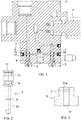
- connection piece 11 which can be used for connecting three fuel pipes of a fuel injection system to each other.
- the connection piece 11 forms part of a fuel injection system of an internal combustion engine.
- the engine is a large piston engine, such as a main or an auxiliary engine of a ship or an engine that is used at a power plant for producing electricity.
- the fuel injection system is configured to inject liquid fuel, such as light fuel oil, marine diesel oil or methanol into the cylinders of the engine.
- the fuel injection system can be, for instance, a common rail fuel injection system.
- the fuel pipes 4 are high-pressure pipes that can supply fuel for instance from a high-pressure pump to fuel injectors.
- Each fuel pipe 4 has a double-wall construction.
- the pressurized fuel is conveyed in an inner pipe and a leakage channel is formed between the inner pipe and an outer pipe. In case there is a leakage in the inner pipe, the leaking fuel is received by the leakage channel.
- the connection piece 11 is provided with a leakage detection arrangement according to an embodiment of the invention.
- the leakage detection arrangement comprises a fluid chamber 1, which is in fluid communication with a leakage channel 2, 3.
- the connection piece 11 of figure 1 comprises a first leakage channel 2 and a second leakage channel 3.
- Each leakage channel 2, 3 of the connection piece 11 is in fluid communication with a leakage channel of a fuel pipe 4.
- the fuel leaking from a fuel pipe 4 is thus received by a leakage channel 2, 3 of the connection piece 11.
- each fuel pipe 4 can be connected to an own leakage channel 2, 3. This makes it easier to locate a leakage.
- several components of the fuel injection system could also be connected to a common leakage channel 2, 3.
- the leakage detection arrangement further comprises an indicator element 5.
- the indicator element 5 is a part, which is movable in the direction of its longitudinal axis.
- the indicator element 5 has a first position and a second position. The first position is a retracted position and the second position is a protruding position.
- the indicator element 5 is put in the retracted position.
- the indicator element 5 is configured to move from the retracted position to the protruding position due to fuel pressure in the fluid chamber 1.
- leaking fuel flows via a leakage channel 2, 3 to the fluid chamber 1, the fuel pressure in the fluid chamber 1 pushes the indicator element 5 to the protruding position.
- the position of the indicator element 5 can be perceived from the outside of the leakage detection arrangement, and a leakage can thus be visually detected.
- the leakage detection arrangement could also be provided with a sensor that monitors the position of the indicator element 5, which would allow automatic leakage monitoring.
- the fuel injection system can be provided with a plurality of leakage detection arrangements. By connecting a leakage detection arrangement only to one or a few leakage channels, the leakages can be easily located.
- the indicator element 5 has a first end and a second end.
- the first end of the indicator element 5 comprises a piston having a piston surface 12, onto which the pressure in the fluid chamber 1 is applied.
- the piston surface 12 delimits the fluid chamber 1.
- An elongated stem 15 is connected to the piston of the indicator element 5.
- the indicator element 5 comprises a first sealing groove 13 and a second sealing groove 14.
- the sealing grooves 13, 14 are circumferential grooves that are arranged close to the first end of the indicator element 5.
- Each of the sealing grooves 13, 14 accommodates an O-ring 16, 17.
- the O-rings 16, 17 are on opposite sides of a drain line 18, which is perpendicular to the longitudinal direction of the indicator element 5.
- the O-ring 16 located in the first sealing groove 13 prevents flow from the leakage channel 2, 3 into the drain line 18.
- the O-ring 17 of the second sealing groove 14 prevents outflow from the drain line 18 past the indicator element 5. In the protruding position of the indicator element 5, flow from the leakage channel 2, 3 into the drain line 18 is allowed.
- the leakage detection arrangement comprises a holding element 8, which limits the movement of the indicator element 5.
- the holding element 8 allows the movement of the indicator element 5 between the retracted position and the protruding position, but prevents the indicator element 5 from falling out of the connection piece 11.
- the holding element is a nut 8, which can be attached to the connection piece 11 by means of threads.
- the holding element 8 could also be a plate or a block or a similar part, which is attached to the connection piece 11 for instance by means of bolts.
- the holding element 8 comprises a bore 10, which can receive the stem 15 of the indicator element 5. In figure 1 , both indicator elements 5 are in the retracted position.
- the second end of the indicator element 5 does not protrude out of the holding element 8.
- the second end protrudes out of the holding element 8 so that it can be easily detected from the outside of the connection piece 11 that the indicator element 5 is in the protruding position.
- the indicator element 5 protrudes out of the holding element 8 also in the retracted position.
- the stem 15 of the indicator element 5 can be provided with a marking which clearly indicates whether the indicator element 5 is in the retracted or in the protruding position.
- the leakage detection arrangement is provided with a retaining element 6.
- the retaining element 6 is engaged with both the indicator element 5 and the holding element 8 and configured to keep the indicator element 5 in the retracted position, unless a longitudinal force applied to the indicator element 5 exceeds a predetermined threshold value. The normal vibrations of the engine do thus not move the indicator element 5, but when the fuel pressure in the fluid chamber 1 is sufficient, the indicator element 5 can move from the retracted position to the protruding position.
- the retaining element 6 is a resilient annular member, such as a snap ring. When the retaining element 6 is not compressed or stretched, the outer diameter of the retaining element 6 is greater than the diameter of the bore 10 of the holding element 8 and the inner diameter of the retaining element 6 is smaller than the diameter of the bore 10.
- the indicator element 5 is provided with a groove 9 for receiving the retaining element 6.
- the groove 9 encircles the stem 15 of the indicator element 5.
- the cross-sectional shape of the groove 9 is rounded.
- the cross-section of the groove 9 can be, for instance, a semicircle.
- the depth of the groove 9 is less than half of the thickness of the retaining element 6 in the radial direction.
- the holding element 8 is provided with a groove 7 for accommodating the retaining element 6.
- the depth of the groove 7 of the holding element 8 is at least the same as the thickness of the retaining element 6 in the radial direction. The retaining element 6 can thus be received completely inside the groove 7 of the holding element 8.
- the retaining element 6 When the indicator element 5 is in the retracted position as shown in figure 1 , the retaining element 6 is engaged both with the groove 9 of the indicator element 5 and the groove 7 of the holding member 8. The retaining element 6 is in a slightly expanded state. When the indicator element 5 is pushed by the fuel pressure towards the protruding position and the force exerted by the fuel pressure exceeds the force that keeps the retaining element 6 in the groove 9 of the indicator element 5, the retaining element 6 jumps out of the groove 9 of the indicator element 5. The form locking between the retaining element 6 and the indicator element 5 is thus released and the indicator element 5 can move towards the protruding position. The groove 7 now receives the retaining element 6 completely.
- the indicator element 5 When the leakage causing the movement of the indicator element 5 has been detected and repaired, the indicator element 5 needs to be put back to the retracted position. This can be done by simply pushing the indicator element 5 towards the retracted position. Since the groove 7 of the holding element 8 holds the retaining element 6, the retaining element 6 is not allowed to move together with the indicator element 5. When the indicator element 5 receives the position where the groove 9 of the indicator element 5 is aligned with the groove 7 of the holding element 8, the retaining element 6 is locked with the groove 9 of the indicator element 5. Due to the groove 7 of the holding element 8, resetting of the leakage detection arrangement is easy and does not require dismounting of any parts.
- One end of the bore 10 of the holding member 8 is provided with a tapered section 10a, which tapers towards the inside of the holding member 8.
- the wider end of the tapered section 10a opens onto an outer surface of the holding member 8.
- the diameter of the tapered section 10a at the wider end is greater than the outer diameter of the retaining element 6. This facilitates the insertion of the retaining element 6 into the groove 7 of the holding element 8, since the retaining element 6 is gradually compressed when being inserted into the groove 7.
- the tapered section 10a is arranged at that end of the bore 10, which faces the fluid chamber 1 of the leakage detection arrangement.
- an end of the stem 15 of the indicator element 5 is tapered.
- the indicator element 5 thus tapers towards the second end of the indicator element 5.
- the indicator element 5 can therefore be easily inserted into the bore 10 of the holding element 8, since the stem 15 of the indicator element 5 gradually expands the retaining element 6 that has been inserted into the groove 7 of the holding element 8.
- the leakage detection arrangement of the figures is arranged in a connection piece, but the leakage detection arrangement could also be, for instance, a separate module, which can be connected to a leakage channel of a fuel pipe or some other component of a fuel injection system.
Landscapes
- Engineering & Computer Science (AREA)
- Chemical & Material Sciences (AREA)
- Combustion & Propulsion (AREA)
- Mechanical Engineering (AREA)
- General Engineering & Computer Science (AREA)
- Fuel-Injection Apparatus (AREA)
- Examining Or Testing Airtightness (AREA)
Claims (6)
- Agencement de détection de fuite pour détecter une fuite dans un système d'injection de carburant d'un moteur à combustion interne, l'agencement comprenant- une chambre de fluide (1) qui peut être agencée en communication fluidique avec un canal de fuite (2, 3) qui est configuré pour recevoir du carburant d'un composant (4) fuyant du système d'injection de carburant,- un élément indicateur (5) ayant une position rétractée et une position en saillie, l'élément indicateur (5) étant configuré pour se déplacer, du fait de la pression du carburant dans la chambre de fluide (1), de la position rétractée à la position en saillie indiquant ainsi une fuite dans le système d'injection de carburant, et- un élément de retenue (6) qui est agencé autour de l'élément indicateur (5) et est configuré pour maintenir l'élément indicateur (5) dans la position rétractée et permettre le mouvement de l'élément indicateur (5) vers la position en saillie lorsque la force appliquée à l'élément indicateur (5) par la pression du carburant dans la chambre de fluide (1) dépasse un seuil prédéterminé,caractérisé en ce que l'agencement est doté d'une rainure (7) qui est agencée dans une partie (8) entourant l'élément indicateur (5) et qui est configurée pour recevoir l'élément de retenue (6), et que l'élément indicateur (5) comprend une rainure (9) qui entoure la circonférence extérieure de l'élément indicateur (5) et qui est configurée pour recevoir l'élément de retenue (6) lorsque l'élément indicateur (5) est dans la position rétractée.
- Agencement selon la revendication 1, dans lequel la rainure (7) est agencée dans un élément de maintien (8) amovible qui permet le montage et le démontage de l'élément indicateur (5).
- Agencement selon la revendication 2, dans lequel l'élément de maintien est un écrou (8).
- Agencement selon la revendication 2 ou 3, dans lequel l'élément de maintien (8) comprend un alésage (10) à travers lequel l'élément indicateur (5) fait saillie et une extrémité de l'alésage (10) est dotée d'une section (10a) qui décroît en direction de l'intérieur de l'élément de maintien (8).
- Agencement selon l'une quelconque des revendications précédentes, dans lequel l'extrémité avant de l'élément indicateur (5) dans la direction de la position rétractée vers la position en saillie décroît en direction de ladite extrémité.
- Agencement selon l'une quelconque des revendications précédentes, dans lequel l'élément de retenue (6) est un circlip.
Applications Claiming Priority (1)
| Application Number | Priority Date | Filing Date | Title |
|---|---|---|---|
| PCT/FI2015/050677 WO2017060561A1 (fr) | 2015-10-09 | 2015-10-09 | Agencement de détection de fuite |
Publications (2)
| Publication Number | Publication Date |
|---|---|
| EP3359801A1 EP3359801A1 (fr) | 2018-08-15 |
| EP3359801B1 true EP3359801B1 (fr) | 2019-07-17 |
Family
ID=54477000
Family Applications (1)
| Application Number | Title | Priority Date | Filing Date |
|---|---|---|---|
| EP15791000.1A Active EP3359801B1 (fr) | 2015-10-09 | 2015-10-09 | Agencement de détection de fuite |
Country Status (4)
| Country | Link |
|---|---|
| EP (1) | EP3359801B1 (fr) |
| KR (1) | KR102068917B1 (fr) |
| CN (1) | CN108368808B (fr) |
| WO (1) | WO2017060561A1 (fr) |
Cited By (1)
| Publication number | Priority date | Publication date | Assignee | Title |
|---|---|---|---|---|
| EP4374059A1 (fr) * | 2021-10-04 | 2024-05-29 | Woodward, Inc. | Vis pare-flammes |
Families Citing this family (1)
| Publication number | Priority date | Publication date | Assignee | Title |
|---|---|---|---|---|
| CN112031970B (zh) * | 2020-08-28 | 2022-03-11 | 广东海洋大学 | 一种具有泄漏监测功能的共轨柴油机高压油管连接装置 |
Family Cites Families (6)
| Publication number | Priority date | Publication date | Assignee | Title |
|---|---|---|---|---|
| GB2060800B (en) * | 1979-08-08 | 1983-07-13 | Giro Eng Ltd | Fitting for double wall tubing |
| JP3918253B2 (ja) * | 1997-09-10 | 2007-05-23 | 三菱ふそうトラック・バス株式会社 | 蓄圧式燃料噴射装置の安全装置 |
| FI119702B (fi) * | 2003-10-17 | 2009-02-13 | Waertsilae Finland Oy | Polttomoottorin laitteisto korkeapaineputken vuotoja varten |
| JP2005344622A (ja) * | 2004-06-03 | 2005-12-15 | Bosch Corp | 燃料噴射弁 |
| EP2011996B1 (fr) * | 2007-07-04 | 2012-03-14 | Caterpillar Motoren GmbH & Co. KG | Système de carburant pour moteur à combustion équipé d'un détecteur de fuites locales |
| FI20115126L (fi) * | 2011-02-09 | 2012-08-10 | Waertsilae Finland Oy | Polttoaineen ruiskutusjärjestelmä |
-
2015
- 2015-10-09 KR KR1020187013076A patent/KR102068917B1/ko active Active
- 2015-10-09 WO PCT/FI2015/050677 patent/WO2017060561A1/fr not_active Ceased
- 2015-10-09 EP EP15791000.1A patent/EP3359801B1/fr active Active
- 2015-10-09 CN CN201580085069.1A patent/CN108368808B/zh active Active
Non-Patent Citations (1)
| Title |
|---|
| None * |
Cited By (1)
| Publication number | Priority date | Publication date | Assignee | Title |
|---|---|---|---|---|
| EP4374059A1 (fr) * | 2021-10-04 | 2024-05-29 | Woodward, Inc. | Vis pare-flammes |
Also Published As
| Publication number | Publication date |
|---|---|
| WO2017060561A1 (fr) | 2017-04-13 |
| KR102068917B1 (ko) | 2020-01-21 |
| CN108368808B (zh) | 2020-06-30 |
| KR20180059942A (ko) | 2018-06-05 |
| CN108368808A (zh) | 2018-08-03 |
| EP3359801A1 (fr) | 2018-08-15 |
Similar Documents
| Publication | Publication Date | Title |
|---|---|---|
| CN101796290B (zh) | 用于内燃机的具有局部泄漏检测的燃料系统 | |
| EP2042691A2 (fr) | Ensemble de tube de lubrifiant pour turbine | |
| CN109555628B (zh) | 燃料分配器 | |
| RU2652856C2 (ru) | Фитинг для системы защиты трубопровода | |
| EP3359801B1 (fr) | Agencement de détection de fuite | |
| EP2584229B1 (fr) | Système et procédé de blindage d'un joint torique | |
| RU2667212C2 (ru) | Структура концевого уплотнения топливной рампы для бензинового двигателя с прямым впрыском топлива | |
| US10030619B2 (en) | Connector for mounting sensor in pressurized fluid system | |
| US9382871B2 (en) | Method for repair of cylinder block including water ferrule | |
| CN108225688B (zh) | 泄漏检测工具 | |
| JP5232435B2 (ja) | 内燃機関の燃料供給装置 | |
| EP2935856B1 (fr) | Agencement d'alimentation en combustible d'un moteur | |
| US20170082517A1 (en) | Leak detection system | |
| KR20180100650A (ko) | 파이프 조립체 및 파이프 조립체의 연결 방법 | |
| CN210919301U (zh) | 一种低速机整体式共轨 | |
| WO2018189415A1 (fr) | Soupape d'arrêt | |
| KR101425301B1 (ko) | 대형 밸브용 실란트 피팅의 이중 결합식 설치구조 | |
| CN106460753A (zh) | 燃料喷射器的燃料供给装置和燃料喷射器 | |
| CN105422348B (zh) | 一种基于康明斯pt喷油器检测实验的密封分流装置 | |
| KR20150092325A (ko) | 엔진을 위한 셧다운 시스템 및 셧다운 시스템을 모니터링하기 위한 방법 | |
| WO2015143431A9 (fr) | Raccord de lubrification/de purgeur | |
| US12546424B1 (en) | Fluid coupler with positive engagement indicator | |
| US7549678B2 (en) | Systems for actuating a pipe connection | |
| US20160265708A1 (en) | Leak check device | |
| KR101471209B1 (ko) | 내연 엔진의 연료 공급 시스템 |
Legal Events
| Date | Code | Title | Description |
|---|---|---|---|
| STAA | Information on the status of an ep patent application or granted ep patent |
Free format text: STATUS: THE INTERNATIONAL PUBLICATION HAS BEEN MADE |
|
| PUAI | Public reference made under article 153(3) epc to a published international application that has entered the european phase |
Free format text: ORIGINAL CODE: 0009012 |
|
| STAA | Information on the status of an ep patent application or granted ep patent |
Free format text: STATUS: REQUEST FOR EXAMINATION WAS MADE |
|
| 17P | Request for examination filed |
Effective date: 20180502 |
|
| AK | Designated contracting states |
Kind code of ref document: A1 Designated state(s): AL AT BE BG CH CY CZ DE DK EE ES FI FR GB GR HR HU IE IS IT LI LT LU LV MC MK MT NL NO PL PT RO RS SE SI SK SM TR |
|
| AX | Request for extension of the european patent |
Extension state: BA ME |
|
| RAP1 | Party data changed (applicant data changed or rights of an application transferred) |
Owner name: WAERTSILAE FINLAND OY |
|
| DAV | Request for validation of the european patent (deleted) | ||
| DAX | Request for extension of the european patent (deleted) | ||
| GRAP | Despatch of communication of intention to grant a patent |
Free format text: ORIGINAL CODE: EPIDOSNIGR1 |
|
| STAA | Information on the status of an ep patent application or granted ep patent |
Free format text: STATUS: GRANT OF PATENT IS INTENDED |
|
| INTG | Intention to grant announced |
Effective date: 20190219 |
|
| GRAS | Grant fee paid |
Free format text: ORIGINAL CODE: EPIDOSNIGR3 |
|
| GRAA | (expected) grant |
Free format text: ORIGINAL CODE: 0009210 |
|
| STAA | Information on the status of an ep patent application or granted ep patent |
Free format text: STATUS: THE PATENT HAS BEEN GRANTED |
|
| AK | Designated contracting states |
Kind code of ref document: B1 Designated state(s): AL AT BE BG CH CY CZ DE DK EE ES FI FR GB GR HR HU IE IS IT LI LT LU LV MC MK MT NL NO PL PT RO RS SE SI SK SM TR |
|
| REG | Reference to a national code |
Ref country code: GB Ref legal event code: FG4D |
|
| REG | Reference to a national code |
Ref country code: CH Ref legal event code: EP |
|
| REG | Reference to a national code |
Ref country code: IE Ref legal event code: FG4D |
|
| REG | Reference to a national code |
Ref country code: DE Ref legal event code: R096 Ref document number: 602015033990 Country of ref document: DE |
|
| REG | Reference to a national code |
Ref country code: AT Ref legal event code: REF Ref document number: 1156062 Country of ref document: AT Kind code of ref document: T Effective date: 20190815 |
|
| REG | Reference to a national code |
Ref country code: NL Ref legal event code: MP Effective date: 20190717 |
|
| REG | Reference to a national code |
Ref country code: NO Ref legal event code: T2 Effective date: 20190717 |
|
| REG | Reference to a national code |
Ref country code: LT Ref legal event code: MG4D |
|
| PG25 | Lapsed in a contracting state [announced via postgrant information from national office to epo] |
Ref country code: FI Free format text: LAPSE BECAUSE OF FAILURE TO SUBMIT A TRANSLATION OF THE DESCRIPTION OR TO PAY THE FEE WITHIN THE PRESCRIBED TIME-LIMIT Effective date: 20190717 Ref country code: LT Free format text: LAPSE BECAUSE OF FAILURE TO SUBMIT A TRANSLATION OF THE DESCRIPTION OR TO PAY THE FEE WITHIN THE PRESCRIBED TIME-LIMIT Effective date: 20190717 Ref country code: HR Free format text: LAPSE BECAUSE OF FAILURE TO SUBMIT A TRANSLATION OF THE DESCRIPTION OR TO PAY THE FEE WITHIN THE PRESCRIBED TIME-LIMIT Effective date: 20190717 Ref country code: BG Free format text: LAPSE BECAUSE OF FAILURE TO SUBMIT A TRANSLATION OF THE DESCRIPTION OR TO PAY THE FEE WITHIN THE PRESCRIBED TIME-LIMIT Effective date: 20191017 Ref country code: SE Free format text: LAPSE BECAUSE OF FAILURE TO SUBMIT A TRANSLATION OF THE DESCRIPTION OR TO PAY THE FEE WITHIN THE PRESCRIBED TIME-LIMIT Effective date: 20190717 Ref country code: NL Free format text: LAPSE BECAUSE OF FAILURE TO SUBMIT A TRANSLATION OF THE DESCRIPTION OR TO PAY THE FEE WITHIN THE PRESCRIBED TIME-LIMIT Effective date: 20190717 Ref country code: PT Free format text: LAPSE BECAUSE OF FAILURE TO SUBMIT A TRANSLATION OF THE DESCRIPTION OR TO PAY THE FEE WITHIN THE PRESCRIBED TIME-LIMIT Effective date: 20191118 |
|
| PG25 | Lapsed in a contracting state [announced via postgrant information from national office to epo] |
Ref country code: ES Free format text: LAPSE BECAUSE OF FAILURE TO SUBMIT A TRANSLATION OF THE DESCRIPTION OR TO PAY THE FEE WITHIN THE PRESCRIBED TIME-LIMIT Effective date: 20190717 Ref country code: GR Free format text: LAPSE BECAUSE OF FAILURE TO SUBMIT A TRANSLATION OF THE DESCRIPTION OR TO PAY THE FEE WITHIN THE PRESCRIBED TIME-LIMIT Effective date: 20191018 Ref country code: AL Free format text: LAPSE BECAUSE OF FAILURE TO SUBMIT A TRANSLATION OF THE DESCRIPTION OR TO PAY THE FEE WITHIN THE PRESCRIBED TIME-LIMIT Effective date: 20190717 Ref country code: LV Free format text: LAPSE BECAUSE OF FAILURE TO SUBMIT A TRANSLATION OF THE DESCRIPTION OR TO PAY THE FEE WITHIN THE PRESCRIBED TIME-LIMIT Effective date: 20190717 Ref country code: IS Free format text: LAPSE BECAUSE OF FAILURE TO SUBMIT A TRANSLATION OF THE DESCRIPTION OR TO PAY THE FEE WITHIN THE PRESCRIBED TIME-LIMIT Effective date: 20191117 Ref country code: RS Free format text: LAPSE BECAUSE OF FAILURE TO SUBMIT A TRANSLATION OF THE DESCRIPTION OR TO PAY THE FEE WITHIN THE PRESCRIBED TIME-LIMIT Effective date: 20190717 |
|
| PG25 | Lapsed in a contracting state [announced via postgrant information from national office to epo] |
Ref country code: TR Free format text: LAPSE BECAUSE OF FAILURE TO SUBMIT A TRANSLATION OF THE DESCRIPTION OR TO PAY THE FEE WITHIN THE PRESCRIBED TIME-LIMIT Effective date: 20190717 |
|
| PG25 | Lapsed in a contracting state [announced via postgrant information from national office to epo] |
Ref country code: DK Free format text: LAPSE BECAUSE OF FAILURE TO SUBMIT A TRANSLATION OF THE DESCRIPTION OR TO PAY THE FEE WITHIN THE PRESCRIBED TIME-LIMIT Effective date: 20190717 Ref country code: PL Free format text: LAPSE BECAUSE OF FAILURE TO SUBMIT A TRANSLATION OF THE DESCRIPTION OR TO PAY THE FEE WITHIN THE PRESCRIBED TIME-LIMIT Effective date: 20190717 Ref country code: EE Free format text: LAPSE BECAUSE OF FAILURE TO SUBMIT A TRANSLATION OF THE DESCRIPTION OR TO PAY THE FEE WITHIN THE PRESCRIBED TIME-LIMIT Effective date: 20190717 Ref country code: RO Free format text: LAPSE BECAUSE OF FAILURE TO SUBMIT A TRANSLATION OF THE DESCRIPTION OR TO PAY THE FEE WITHIN THE PRESCRIBED TIME-LIMIT Effective date: 20190717 |
|
| PG25 | Lapsed in a contracting state [announced via postgrant information from national office to epo] |
Ref country code: SK Free format text: LAPSE BECAUSE OF FAILURE TO SUBMIT A TRANSLATION OF THE DESCRIPTION OR TO PAY THE FEE WITHIN THE PRESCRIBED TIME-LIMIT Effective date: 20190717 Ref country code: IS Free format text: LAPSE BECAUSE OF FAILURE TO SUBMIT A TRANSLATION OF THE DESCRIPTION OR TO PAY THE FEE WITHIN THE PRESCRIBED TIME-LIMIT Effective date: 20200224 Ref country code: SM Free format text: LAPSE BECAUSE OF FAILURE TO SUBMIT A TRANSLATION OF THE DESCRIPTION OR TO PAY THE FEE WITHIN THE PRESCRIBED TIME-LIMIT Effective date: 20190717 Ref country code: MC Free format text: LAPSE BECAUSE OF FAILURE TO SUBMIT A TRANSLATION OF THE DESCRIPTION OR TO PAY THE FEE WITHIN THE PRESCRIBED TIME-LIMIT Effective date: 20190717 Ref country code: CZ Free format text: LAPSE BECAUSE OF FAILURE TO SUBMIT A TRANSLATION OF THE DESCRIPTION OR TO PAY THE FEE WITHIN THE PRESCRIBED TIME-LIMIT Effective date: 20190717 |
|
| REG | Reference to a national code |
Ref country code: CH Ref legal event code: PL |
|
| REG | Reference to a national code |
Ref country code: DE Ref legal event code: R097 Ref document number: 602015033990 Country of ref document: DE |
|
| PLBE | No opposition filed within time limit |
Free format text: ORIGINAL CODE: 0009261 |
|
| STAA | Information on the status of an ep patent application or granted ep patent |
Free format text: STATUS: NO OPPOSITION FILED WITHIN TIME LIMIT |
|
| PG2D | Information on lapse in contracting state deleted |
Ref country code: IS |
|
| PG25 | Lapsed in a contracting state [announced via postgrant information from national office to epo] |
Ref country code: CH Free format text: LAPSE BECAUSE OF NON-PAYMENT OF DUE FEES Effective date: 20191031 Ref country code: LI Free format text: LAPSE BECAUSE OF NON-PAYMENT OF DUE FEES Effective date: 20191031 Ref country code: LU Free format text: LAPSE BECAUSE OF NON-PAYMENT OF DUE FEES Effective date: 20191009 |
|
| 26N | No opposition filed |
Effective date: 20200603 |
|
| REG | Reference to a national code |
Ref country code: BE Ref legal event code: MM Effective date: 20191031 |
|
| PG25 | Lapsed in a contracting state [announced via postgrant information from national office to epo] |
Ref country code: SI Free format text: LAPSE BECAUSE OF FAILURE TO SUBMIT A TRANSLATION OF THE DESCRIPTION OR TO PAY THE FEE WITHIN THE PRESCRIBED TIME-LIMIT Effective date: 20190717 Ref country code: BE Free format text: LAPSE BECAUSE OF NON-PAYMENT OF DUE FEES Effective date: 20191031 |
|
| GBPC | Gb: european patent ceased through non-payment of renewal fee |
Effective date: 20191017 |
|
| PG25 | Lapsed in a contracting state [announced via postgrant information from national office to epo] |
Ref country code: FR Free format text: LAPSE BECAUSE OF NON-PAYMENT OF DUE FEES Effective date: 20191031 Ref country code: GB Free format text: LAPSE BECAUSE OF NON-PAYMENT OF DUE FEES Effective date: 20191017 Ref country code: IE Free format text: LAPSE BECAUSE OF NON-PAYMENT OF DUE FEES Effective date: 20191009 |
|
| PG25 | Lapsed in a contracting state [announced via postgrant information from national office to epo] |
Ref country code: CY Free format text: LAPSE BECAUSE OF FAILURE TO SUBMIT A TRANSLATION OF THE DESCRIPTION OR TO PAY THE FEE WITHIN THE PRESCRIBED TIME-LIMIT Effective date: 20190717 |
|
| REG | Reference to a national code |
Ref country code: AT Ref legal event code: UEP Ref document number: 1156062 Country of ref document: AT Kind code of ref document: T Effective date: 20190717 |
|
| PG25 | Lapsed in a contracting state [announced via postgrant information from national office to epo] |
Ref country code: MT Free format text: LAPSE BECAUSE OF FAILURE TO SUBMIT A TRANSLATION OF THE DESCRIPTION OR TO PAY THE FEE WITHIN THE PRESCRIBED TIME-LIMIT Effective date: 20190717 Ref country code: HU Free format text: LAPSE BECAUSE OF FAILURE TO SUBMIT A TRANSLATION OF THE DESCRIPTION OR TO PAY THE FEE WITHIN THE PRESCRIBED TIME-LIMIT; INVALID AB INITIO Effective date: 20151009 |
|
| PG25 | Lapsed in a contracting state [announced via postgrant information from national office to epo] |
Ref country code: MK Free format text: LAPSE BECAUSE OF FAILURE TO SUBMIT A TRANSLATION OF THE DESCRIPTION OR TO PAY THE FEE WITHIN THE PRESCRIBED TIME-LIMIT Effective date: 20190717 |
|
| PGFP | Annual fee paid to national office [announced via postgrant information from national office to epo] |
Ref country code: DE Payment date: 20251021 Year of fee payment: 11 |
|
| PGFP | Annual fee paid to national office [announced via postgrant information from national office to epo] |
Ref country code: NO Payment date: 20251024 Year of fee payment: 11 |
|
| PGFP | Annual fee paid to national office [announced via postgrant information from national office to epo] |
Ref country code: AT Payment date: 20251022 Year of fee payment: 11 |
|
| PGFP | Annual fee paid to national office [announced via postgrant information from national office to epo] |
Ref country code: IT Payment date: 20251024 Year of fee payment: 11 |