EP3359906B1 - Ölfeldperforator zum entfernen eines hochvolumigen gehäuses - Google Patents
Ölfeldperforator zum entfernen eines hochvolumigen gehäuses Download PDFInfo
- Publication number
- EP3359906B1 EP3359906B1 EP16782370.7A EP16782370A EP3359906B1 EP 3359906 B1 EP3359906 B1 EP 3359906B1 EP 16782370 A EP16782370 A EP 16782370A EP 3359906 B1 EP3359906 B1 EP 3359906B1
- Authority
- EP
- European Patent Office
- Prior art keywords
- wellbore
- shaped charge
- charge
- work string
- detonating cord
- Prior art date
- Legal status (The legal status is an assumption and is not a legal conclusion. Google has not performed a legal analysis and makes no representation as to the accuracy of the status listed.)
- Not-in-force
Links
- 239000002360 explosive Substances 0.000 claims description 12
- 239000000463 material Substances 0.000 claims description 12
- 229910052751 metal Inorganic materials 0.000 claims description 11
- 239000002184 metal Substances 0.000 claims description 11
- 239000012530 fluid Substances 0.000 claims description 9
- 238000000034 method Methods 0.000 claims description 7
- 239000007788 liquid Substances 0.000 claims description 5
- 238000010304 firing Methods 0.000 claims description 4
- 229930195733 hydrocarbon Natural products 0.000 description 5
- 150000002430 hydrocarbons Chemical class 0.000 description 5
- 150000002739 metals Chemical class 0.000 description 5
- 239000007789 gas Substances 0.000 description 4
- 230000015572 biosynthetic process Effects 0.000 description 3
- 239000000203 mixture Substances 0.000 description 3
- 239000004215 Carbon black (E152) Substances 0.000 description 2
- XEEYBQQBJWHFJM-UHFFFAOYSA-N Iron Chemical compound [Fe] XEEYBQQBJWHFJM-UHFFFAOYSA-N 0.000 description 2
- PXHVJJICTQNCMI-UHFFFAOYSA-N Nickel Chemical compound [Ni] PXHVJJICTQNCMI-UHFFFAOYSA-N 0.000 description 2
- 239000011230 binding agent Substances 0.000 description 2
- 238000010276 construction Methods 0.000 description 2
- 238000005474 detonation Methods 0.000 description 2
- 238000005553 drilling Methods 0.000 description 2
- 230000000694 effects Effects 0.000 description 2
- 238000004519 manufacturing process Methods 0.000 description 2
- 230000007246 mechanism Effects 0.000 description 2
- VNWKTOKETHGBQD-UHFFFAOYSA-N methane Chemical compound C VNWKTOKETHGBQD-UHFFFAOYSA-N 0.000 description 2
- 229910000906 Bronze Inorganic materials 0.000 description 1
- RYGMFSIKBFXOCR-UHFFFAOYSA-N Copper Chemical compound [Cu] RYGMFSIKBFXOCR-UHFFFAOYSA-N 0.000 description 1
- ZOKXTWBITQBERF-UHFFFAOYSA-N Molybdenum Chemical compound [Mo] ZOKXTWBITQBERF-UHFFFAOYSA-N 0.000 description 1
- BQCADISMDOOEFD-UHFFFAOYSA-N Silver Chemical compound [Ag] BQCADISMDOOEFD-UHFFFAOYSA-N 0.000 description 1
- 229910000831 Steel Inorganic materials 0.000 description 1
- ATJFFYVFTNAWJD-UHFFFAOYSA-N Tin Chemical compound [Sn] ATJFFYVFTNAWJD-UHFFFAOYSA-N 0.000 description 1
- 229910052770 Uranium Inorganic materials 0.000 description 1
- HCHKCACWOHOZIP-UHFFFAOYSA-N Zinc Chemical compound [Zn] HCHKCACWOHOZIP-UHFFFAOYSA-N 0.000 description 1
- 229910052787 antimony Inorganic materials 0.000 description 1
- WATWJIUSRGPENY-UHFFFAOYSA-N antimony atom Chemical compound [Sb] WATWJIUSRGPENY-UHFFFAOYSA-N 0.000 description 1
- 230000005540 biological transmission Effects 0.000 description 1
- 239000012267 brine Substances 0.000 description 1
- 239000010974 bronze Substances 0.000 description 1
- 229910010293 ceramic material Inorganic materials 0.000 description 1
- 229910017052 cobalt Inorganic materials 0.000 description 1
- 239000010941 cobalt Substances 0.000 description 1
- GUTLYIVDDKVIGB-UHFFFAOYSA-N cobalt atom Chemical compound [Co] GUTLYIVDDKVIGB-UHFFFAOYSA-N 0.000 description 1
- 238000004891 communication Methods 0.000 description 1
- 229910052802 copper Inorganic materials 0.000 description 1
- 239000010949 copper Substances 0.000 description 1
- KUNSUQLRTQLHQQ-UHFFFAOYSA-N copper tin Chemical compound [Cu].[Sn] KUNSUQLRTQLHQQ-UHFFFAOYSA-N 0.000 description 1
- PCHJSUWPFVWCPO-UHFFFAOYSA-N gold Chemical compound [Au] PCHJSUWPFVWCPO-UHFFFAOYSA-N 0.000 description 1
- 229910052737 gold Inorganic materials 0.000 description 1
- 239000010931 gold Substances 0.000 description 1
- 229910052742 iron Inorganic materials 0.000 description 1
- 239000011133 lead Substances 0.000 description 1
- 239000011159 matrix material Substances 0.000 description 1
- 229910052750 molybdenum Inorganic materials 0.000 description 1
- 239000011733 molybdenum Substances 0.000 description 1
- 239000003345 natural gas Substances 0.000 description 1
- 229910052759 nickel Inorganic materials 0.000 description 1
- -1 oil and gas Chemical class 0.000 description 1
- 239000012255 powdered metal Substances 0.000 description 1
- 238000011084 recovery Methods 0.000 description 1
- 230000008054 signal transmission Effects 0.000 description 1
- 229910052709 silver Inorganic materials 0.000 description 1
- 239000004332 silver Substances 0.000 description 1
- HPALAKNZSZLMCH-UHFFFAOYSA-M sodium;chloride;hydrate Chemical compound O.[Na+].[Cl-] HPALAKNZSZLMCH-UHFFFAOYSA-M 0.000 description 1
- 239000007787 solid Substances 0.000 description 1
- 125000006850 spacer group Chemical group 0.000 description 1
- 239000010959 steel Substances 0.000 description 1
- 229910052715 tantalum Inorganic materials 0.000 description 1
- GUVRBAGPIYLISA-UHFFFAOYSA-N tantalum atom Chemical compound [Ta] GUVRBAGPIYLISA-UHFFFAOYSA-N 0.000 description 1
- 229910052718 tin Inorganic materials 0.000 description 1
- 239000011135 tin Substances 0.000 description 1
- WFKWXMTUELFFGS-UHFFFAOYSA-N tungsten Chemical compound [W] WFKWXMTUELFFGS-UHFFFAOYSA-N 0.000 description 1
- 229910052721 tungsten Inorganic materials 0.000 description 1
- 239000010937 tungsten Substances 0.000 description 1
- JFALSRSLKYAFGM-UHFFFAOYSA-N uranium(0) Chemical compound [U] JFALSRSLKYAFGM-UHFFFAOYSA-N 0.000 description 1
- XLYOFNOQVPJJNP-UHFFFAOYSA-N water Substances O XLYOFNOQVPJJNP-UHFFFAOYSA-N 0.000 description 1
- 230000003313 weakening effect Effects 0.000 description 1
- 229910052725 zinc Inorganic materials 0.000 description 1
- 239000011701 zinc Substances 0.000 description 1
Images

Classifications
-
- E—FIXED CONSTRUCTIONS
- E21—EARTH OR ROCK DRILLING; MINING
- E21B—EARTH OR ROCK DRILLING; OBTAINING OIL, GAS, WATER, SOLUBLE OR MELTABLE MATERIALS OR A SLURRY OF MINERALS FROM WELLS
- E21B43/00—Methods or apparatus for obtaining oil, gas, water, soluble or meltable materials or a slurry of minerals from wells
- E21B43/11—Perforators; Permeators
- E21B43/116—Gun or shaped-charge perforators
- E21B43/117—Shaped-charge perforators
-
- E—FIXED CONSTRUCTIONS
- E21—EARTH OR ROCK DRILLING; MINING
- E21B—EARTH OR ROCK DRILLING; OBTAINING OIL, GAS, WATER, SOLUBLE OR MELTABLE MATERIALS OR A SLURRY OF MINERALS FROM WELLS
- E21B31/00—Fishing for or freeing objects in boreholes or wells
- E21B31/002—Destroying the objects to be fished, e.g. by explosive means
-
- E—FIXED CONSTRUCTIONS
- E21—EARTH OR ROCK DRILLING; MINING
- E21B—EARTH OR ROCK DRILLING; OBTAINING OIL, GAS, WATER, SOLUBLE OR MELTABLE MATERIALS OR A SLURRY OF MINERALS FROM WELLS
- E21B43/00—Methods or apparatus for obtaining oil, gas, water, soluble or meltable materials or a slurry of minerals from wells
- E21B43/11—Perforators; Permeators
- E21B43/119—Details, e.g. for locating perforating place or direction
-
- F—MECHANICAL ENGINEERING; LIGHTING; HEATING; WEAPONS; BLASTING
- F42—AMMUNITION; BLASTING
- F42B—EXPLOSIVE CHARGES, e.g. FOR BLASTING, FIREWORKS, AMMUNITION
- F42B1/00—Explosive charges characterised by form or shape but not dependent on shape of container
- F42B1/02—Shaped or hollow charges
- F42B1/028—Shaped or hollow charges characterised by the form of the liner
Definitions
- the present disclosure relates to devices and methods for subsurface perforating.
- Hydrocarbons such as oil and gas
- Hydrocarbons are produced from cased wellbores intersecting one or more hydrocarbon reservoirs in a formation. These hydrocarbons flow into the wellbore through perforations in the cased wellbore.
- a number of wellbore tubulars may be used in a wellbore in addition to casing. Such tubulars including liners, production tubing, and drill pipe. In some situations, it may be desirable to sever a portion of a wellbore tubular. For example, a drill pipe may become stuck in a wellbore. Removal of the drill pipe may require cutting the drill pipe into two sections. In another example, pipe may need to cut during well abandonment.
- CA 1166954 describes a perforator having an elongated support that includes a series of flat-faced sections and explosive charges mounted perpendicular to the flat faces. Detonating cords are connected to the charges to fire them. Each section of the support has two closely spaced attachment holes adapted to receive respectively the rear parts of the two charges mounted in opposite directions on each face of this section.
- the support is made up of a tube flattened transversely so as to form the flat-faced sections. Spacers are disposed between the charges and the support for casings of large diameter.
- the cases of the charges comprise a cover made of ceramic material and an extruded steel body which tends to flare out when the explosive is detonated rather than being broken into pieces.
- the present disclosure addresses the continuing need for perforators useful for subsurface operations that may take place during the construction, completion, workover, and / or de-commissioning of a well.
- the present disclosure provides a perforating tool for perforating a wellbore tubular in a wellbore, comprising: a work string and a charge holder connected to the work string, the perforating tool further comprising a shaped charge fixed in the charge holder, the shaped charge having: a cylindrical case having a bulkhead at a first end, an open mouth at a second end, and an interior volume, wherein the first end includes a post projecting therefrom, the post having a channel; an explosive material disposed in the interior volume; and a metal cap covering the open mouth of the case, the cap having a disk section defined by a separator ring, the separator ring having a structurally weakened zone that encircles the disk section, wherein the structurally weakened zone is formed by a fold; and a detonating cord received in the channel of the post.
- the present disclosure also provides a method for perforating a wellbore tubular in a wellbore, the method comprising forming a work string, connecting a charge holder to the work string, disposing a detonating cord along the work string, and fixing a shaped charge in the charge holder, the shaped charge having: a cylindrical case having a bulkhead at a first end, an open mouth at a second end, and an interior volume, wherein the first end includes a post projecting therefrom, the post having a channel configured to receive the detonating cord; an explosive material disposed in the interior volume; and a metal cap covering the open mouth of the case, the cap having a disk section defined by a separator ring, the separator ring having a structurally weakened zone that encircles the disk section, wherein the structurally weakened zone is formed by a fold; conveying the work string into the wellbore; positioning the shaped charge in the wellbore tubular; and firing the shaped charge by detonating the
- the present disclosure relates to devices and methods related to subsurface activity such as casing perforating, casing removal, completion, fishing operations to remove wellbore tubulars, etc.
- the present disclosure is susceptible to embodiments of different forms. There are shown in the drawings, and herein will be described in detail, specific embodiments of the present disclosure with the understanding that the present disclosure is to be considered an exemplification of the principles of the disclosure, and is not intended to limit the disclosure to that illustrated and described herein.
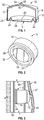
- the shaped charge 10 is designed to generate a large diameter projectile for puncturing, cutting, and / or severing a wellbore structure.
- the shaped charge 10 may include a case 12 and a cap 14 .
- the case 12 may be formed as a cylindrical body 16 with a mouth 18 that is covered by the cap 14 .
- a quantity of explosive material (not shown) may be disposed inside an interior volume 52 of the case 12 , e . g ., RDX, HMX and HNS.
- the cap 14 is configured to generate a large diameter perforator which acts as a projectile that punctures, severs, cuts through, or otherwise perforates an adjacent structure.
- the cap 14 includes a disk section 20 defined by a separator ring 22 .
- An outer circumference 24 of the cap 14 may include a lip 26 in which an edge of the case 12 seats.
- the cap 14 has a face 28 that is formed of the surfaces defining the disk section 20 and the outer circumference 24 .
- the face 28 may be configured to contact the wellbore structure to be cut or have a predetermined stand-off or spacing from an adjacent surface.
- the disk section 20 contains the material which forms the perforator.
- the cap 14 and / or disk section 20 may be formed from a powdered metal mixture that is compressed at high pressures to form a solid mass in the desired shape.
- a high density metal may be included in the mixture in order to achieve the desired effect from the explosive force. Common high density metals used include copper and tungsten, but other high density metals can also be used.
- the mixture of metals typically contains various other ductile metals being combined within the matrix to serve as a binder material. Other binder metals include nickel, lead, silver, gold, zinc, iron, tin, antimony, tantalum, cobalt, bronze, molybdenum and uranium.
- the disk section 20 may be generally flat and circular, but other geometric shapes may also be used ( e . g ., square or triangular). As used herein, the term "flat" is used as a contrast to a conical shape. However, in some embodiments, the flat disk section 20 may use a convex or concave arch to provide pressure integrity.
- the separator ring 22 is a portion of the cap 14 that is defined by a structurally weakened or reduced strength zone 24 that allows the disk section 20 to separate from the cap 14 when the explosives (not shown) inside the case 12 are detonated. A variety of mechanisms may be used to form the separator ring 22 in embodiments where the cap 14 is a single integral body.
- the structurally weakened zone 24 is however formed by a fold.
- the fold may be "V" shaped, "U” shaped, sinusoidal, a square shape, a rectangular, or any other shape having curved or straight sides that are suited for weakening the zone 24 .
- the perforating tool 40 includes a shaped charge 10 fixed in a charge holder 60 and positioned to be in intimate contact with a wellbore tubular 44 .
- the charge holder may be a tube, strip, plate, or other structure that is shaped and configured to point the shaped charge 10 such that the disk section 20 can travel radially outward toward the wellbore tubular 44 .
- intimate contact it is meant that at least a portion of the face 28 ( Fig. 2 ) is in physical contact with the wellbore tubular 44 . In embodiments, it may be desirable to have the face 28 parallel with the surface of the wellbore tubular 44 .
- a majority of the disk section 20 has a surface that is parallel with the surface of the wellbore tubular 44 or, simply, the disk section 20 is substantially parallel with the wellbore tubular 44 .
- a suitable firing system may be used to detonate the shaped charge 10 .
- a detonating cord 46 may be used to detonate the explosive material (not shown) inside the shaped charge 10 .
- the disk section 22 breaks free of the cap 14 along the separator ring 22 and is propelled against the surface of the wellbore tubular 44 . Once free of the cap 14 , the disk section 20 functions as a perforator that cuts through the wellbore tubular 44.
- the perforating tool 40 may be configured such that the shaped charge 10 is in physical contact with wellbore fluids. However, the explosive material inside the case 12 is isolated from contact with such liquids and gases as noted previously.
- the charge holder 60 may be a strip or frame that does not enclose the charge holder 60 .
- the detonating cord 46 may be insulated in a pressure tubing 47 that protects the energetic material of the detonating cord 46 from exposure to the ambient wellbore environment ( e . g ., drilling fluids, fluid pressure, temperature, formation fluids, gases, etc.).
- the explosive material of the detonating cord 46 and the shaped charge 10 do not physically contact fluids in the wellbore such as liquids (e.g., drilling fluids, water, brine, liquid hydrocarbons) or gases (e.g., natural gas, etc.).
- a detonator (not shown) may be used to detonate the detonating cord 46 , which then fires the shaped charge 10 .
- the case 12 may be configured as an encapsulated shaped charge. That is, the case 12 may include an unperforated bulkhead 50 . By “unperforated,” it is meant that there are no openings or passages through the case 12 .
- a post 54 formed at the bulkhead 50 may include a channel 56 for receiving the detonating cord 46 and / or a booster material (not shown).
- the channel 56 may be "blind” in that it does not extend and communicate with the interior 52 .
- the engagement of the outer circumference 24 and the case 12 may also be fluid tight.
- the interior volume 52 of the shaped charge 10 may be hydraulically isolated from the ambient wellbore conditions.
- a conventional case which has a channel, passage, or bore that does communicate with the interior of the case 12 may also be used.
- the facility 100 can include known equipment and structures such as a rig 106 , a wellhead 108 , and casing or other wellbore tubular 44 .
- a work string 112 is suspended within the wellbore 104 from the rig 106 .
- the work string 112 can include drill pipe, coiled tubing, wire line, slick line, or any other known conveyance means.
- the work string 112 can include telemetry lines or other signal/power transmission mediums that establish one-way or two-way telemetric communication.
- a telemetry system may have a surface controller (e.g., a power source) 114 adapted to transmit electrical signals via a cable or signal transmission line 116 disposed in the work string 112 .
- a surface controller e.g., a power source
- the work string 112 may include a downhole tool 120 that as a perforating tool 122 that includes one or more shaped charges according to the present disclosure.
- the perforating tool 122 is positioned at a location 56 such that at least a portion of the face 28 ( Fig. 2 ) of the shaped charge(s) 10 ( Fig. 1 ) is in physical contact with the wellbore tubular 44 .
- the wellbore tubular 44 may be casing, liner, drill string, production tubing, etc.
- a positioning tool 124 may be used to position the perforating tool 122 inside the wellbore tubular 44 .
- the positioning tool 122 may include arms, vanes, or other extendable elements that can contact an adjacent structure and push to the shaped charge 10 ( Fig. 1 ) of the perforating tool 122 into contact with the wellbore tubular 44 .
- the positioning tool 122 may use metal springs, inflatable packers, bladders, hydraulic fluid, or other mechanism to bias the extendable members into the extended position.
- a firing signal from the controller 114 is used to detonate the shaped charge 10 .
- the disk section 20 ( Fig. 2 ) cuts through the wellbore tubular 44 in a manner discussed previously.
Landscapes
- Life Sciences & Earth Sciences (AREA)
- Engineering & Computer Science (AREA)
- Geology (AREA)
- Mining & Mineral Resources (AREA)
- General Life Sciences & Earth Sciences (AREA)
- Fluid Mechanics (AREA)
- Environmental & Geological Engineering (AREA)
- Physics & Mathematics (AREA)
- Geochemistry & Mineralogy (AREA)
- Marine Sciences & Fisheries (AREA)
- General Engineering & Computer Science (AREA)
- Drilling And Exploitation, And Mining Machines And Methods (AREA)
- Perforating, Stamping-Out Or Severing By Means Other Than Cutting (AREA)
- Crushing And Pulverization Processes (AREA)
- Earth Drilling (AREA)
- Pressure Welding/Diffusion-Bonding (AREA)
Claims (7)
- Perforationswerkzeug zum Perforieren eines Bohrlochrohrs in einem Bohrloch, umfassend: einen Arbeitsstrang (112) und eine Sprengladungshülse (60), die mit dem Arbeitsstrang (112) verbunden ist, wobei das Perforationswerkzeug weiterhin Folgendes umfasst:eine Hohlladung (10), die in der Sprengladungshülse (60) fixiert ist, wobei die Hohlladung (10) Folgendes aufweist:- ein zylindrisches Gehäuse (12), das eine Trennwand (50) an einem ersten Ende, eine offene Mündung (18) an einem zweiten Ende und ein Innenvolumen (52) aufweist, wobei das erste Ende eine Säule (54) beinhaltet, die davon hervorragt, wobei die Säule (54) einen Kanal (56) aufweist,- einen Sprengstoff, der in dem Innenvolumen (52) angeordnet ist, und- eine Metallkappe (14), die die offene Mündung (18) des Gehäuses (12) abdeckt, wobei die Kappe (14) einen Scheibenabschnitt (20) aufweist, der durch einen Separatorring (22) definiert ist, wobei der Separatorring (22) eine strukturell geschwächte Zone (24) aufweist, die den Scheibenabschnitt (20) umrandet, wobei die strukturell geschwächte Zone (24) von einer Falz gebildet wird; undeine Detonationszündschnur (46), die in dem Kanal (56) der Säule (54) aufgenommen wird.
- Perforationswerkzeug nach Anspruch 1, weiterhin dadurch gekennzeichnet, dass die Trennwand (50) unperforiert ist und eine fluiddichte Dichtung zwischen der Kappe (14) und dem Gehäuse (12) gebildet ist, um das Innenvolumen (52) des Gehäuses (12) hydraulisch zu isolieren, und wobei die Sprengladungshülse (60) ein Rahmen ist, der die Hohlladung (10) und die Detonationszündschnur (46) gegenüber einer Bohrlochflüssigkeit exponiert.
- Perforationswerkzeug nach Anspruch 1, weiterhin gekennzeichnet durch ein Positionierungswerkzeug, das an dem Arbeitsstrang (112) angeordnet ist, wobei das Positionierungswerkzeug ein ausziehbares Element aufweist, das dazu konfiguriert ist, eine angrenzende Wand zu berühren und die Hohlladung (10) gegen eine Oberfläche des Bohrlochrohrs vorzuspannen.
- Perforationswerkzeug nach Anspruch 1, weiterhin dadurch gekennzeichnet, dass die Falz als eines der folgenden geformt ist: (i) ein "V" und (ii) ein "U".
- Perforationswerkzeug nach Anspruch 1, weiterhin dadurch gekennzeichnet, dass der Scheibenabschnitt (20) flach ist.
- Verfahren zum Perforieren eines Bohrlochrohrs in einem Bohrloch, wobei das Verfahren Folgendes umfasst:Bilden eines Arbeitsstrangs (112), Verbinden einer Sprengladungshülse (60) mit dem Arbeitsstrang (112), Anordnen einer Detonationszündschnur (46) entlang den Arbeitsstrang (112) und Fixieren einer Hohlladung (10) in der Sprengladungshülse (60), wobei die Hohlladung (10) Folgendes aufweist:- ein zylindrisches Gehäuse (12), das eine Trennwand (50) an einem ersten Ende, eine offene Mündung (18) an einem zweiten Ende und ein Innenvolumen (52) aufweist, wobei das erste Ende eine Säule (54) beinhaltet, die davon hervorragt, wobei die Säule (54) einen Kanal (56) aufweist, der dazu konfiguriert ist, die Detonationszündschnur (46) aufzunehmen;- einen Sprengstoff, der in dem Innenvolumen (52) angeordnet ist; und- eine Metallkappe (14), die die offene Mündung (18) des Gehäuses (12) abdeckt, wobei die Kappe (14) einen Scheibenabschnitt (20) aufweist, der durch einen Separatorring (22) definiert ist, wobei der Separatorring (22) eine strukturell geschwächte Zone (24) aufweist, die den Scheibenabschnitt (20) umrandet, wobei die strukturell geschwächte Zone (24) von einer Falz gebildet wird;Befördern des Arbeitsstrangs (112) in das Bohrloch;Positionieren der Hohlladung (10) in dem Bohrlochrohr undZünden der Hohlladung durch Detonieren der Detonationszündschnur (46).
- Verfahren nach Anspruch 6, weiterhin gekennzeichnet durch Exponieren der Hohlladung (10) und der Detonationszündschnur (46) gegenüber einem direkten Kontakt mit einer Flüssigkeit in dem Bohrloch.
Applications Claiming Priority (3)
| Application Number | Priority Date | Filing Date | Title |
|---|---|---|---|
| US201562237302P | 2015-10-05 | 2015-10-05 | |
| US15/285,228 US10240441B2 (en) | 2015-10-05 | 2016-10-04 | Oilfield perforator designed for high volume casing removal |
| PCT/US2016/055482 WO2017062444A1 (en) | 2015-10-05 | 2016-10-05 | Oilfield perforator designed for high volume casing removal |
Publications (2)
| Publication Number | Publication Date |
|---|---|
| EP3359906A1 EP3359906A1 (de) | 2018-08-15 |
| EP3359906B1 true EP3359906B1 (de) | 2019-09-11 |
Family
ID=58447319
Family Applications (1)
| Application Number | Title | Priority Date | Filing Date |
|---|---|---|---|
| EP16782370.7A Not-in-force EP3359906B1 (de) | 2015-10-05 | 2016-10-05 | Ölfeldperforator zum entfernen eines hochvolumigen gehäuses |
Country Status (7)
| Country | Link |
|---|---|
| US (1) | US10240441B2 (de) |
| EP (1) | EP3359906B1 (de) |
| CN (1) | CN108351192B (de) |
| AU (1) | AU2016333891B2 (de) |
| CA (1) | CA3001110C (de) |
| MX (1) | MX2018004097A (de) |
| WO (1) | WO2017062444A1 (de) |
Families Citing this family (16)
| Publication number | Priority date | Publication date | Assignee | Title |
|---|---|---|---|---|
| US9702680B2 (en) | 2013-07-18 | 2017-07-11 | Dynaenergetics Gmbh & Co. Kg | Perforation gun components and system |
| CA3073997C (en) | 2017-09-14 | 2022-06-21 | DynaEnergetics Europe GmbH | Shaped charge liner, shaped charge for high temperature wellbore operations and method of perforating a wellbore using same |
| US10954760B2 (en) | 2017-11-29 | 2021-03-23 | DynaEnergetics Europe GmbH | Closure member and encapsulated slotted shaped charge with closure member |
| US11053782B2 (en) | 2018-04-06 | 2021-07-06 | DynaEnergetics Europe GmbH | Perforating gun system and method of use |
| WO2022084363A1 (en) | 2020-10-20 | 2022-04-28 | DynaEnergetics Europe GmbH | Perforating gun and alignment assembly |
| US12116871B2 (en) | 2019-04-01 | 2024-10-15 | DynaEnergetics Europe GmbH | Retrievable perforating gun assembly and components |
| CA3140643A1 (en) | 2019-05-16 | 2020-11-19 | Schlumberger Canada Limited | Modular perforation tool |
| WO2021185749A1 (en) | 2020-03-16 | 2021-09-23 | DynaEnergetics Europe GmbH | Tandem seal adapter with integrated tracer material |
| USD981345S1 (en) | 2020-11-12 | 2023-03-21 | DynaEnergetics Europe GmbH | Shaped charge casing |
| WO2022104220A1 (en) | 2020-11-13 | 2022-05-19 | Schlumberger Technology Corporation | Oriented-perforation tool |
| NO20230794A1 (en) | 2020-12-21 | 2023-07-17 | DynaEnergetics Europe GmbH | Encapsulated shaped charge |
| WO2022148557A1 (en) | 2021-01-08 | 2022-07-14 | DynaEnergetics Europe GmbH | Perforating gun assembly and components |
| US11499401B2 (en) | 2021-02-04 | 2022-11-15 | DynaEnergetics Europe GmbH | Perforating gun assembly with performance optimized shaped charge load |
| WO2022167297A1 (en) | 2021-02-04 | 2022-08-11 | DynaEnergetics Europe GmbH | Perforating gun assembly with performance optimized shaped charge load |
| US12366142B2 (en) | 2021-03-03 | 2025-07-22 | DynaEnergetics Europe GmbH | Modular perforating gun system |
| US12253339B2 (en) | 2021-10-25 | 2025-03-18 | DynaEnergetics Europe GmbH | Adapter and shaped charge apparatus for optimized perforation jet |
Family Cites Families (29)
| Publication number | Priority date | Publication date | Assignee | Title |
|---|---|---|---|---|
| FR1231003A (fr) | 1946-02-26 | 1960-09-26 | Soc Tech De Rech Ind | Perfectionnements aux engins à charges creuses |
| US2629325A (en) * | 1950-05-20 | 1953-02-24 | William G Sweetman | Jet type perforating unit |
| US2796833A (en) * | 1952-05-10 | 1957-06-25 | William G Sweetman | Perforating devices |
| US3094930A (en) | 1960-05-18 | 1963-06-25 | Schlumberger Well Surv Corp | Expendable perforating apparatus |
| US3233688A (en) | 1963-09-12 | 1966-02-08 | Schlumberger Well Surv Corp | Casing cutter |
| US3245485A (en) | 1963-11-08 | 1966-04-12 | Schlumberger Well Sarveying Co | Tubing cutter |
| US3244101A (en) * | 1964-06-11 | 1966-04-05 | Schlumberger Well Surv Corp | Perforating apparatus |
| US3415321A (en) | 1966-09-09 | 1968-12-10 | Dresser Ind | Shaped charge perforating apparatus and method |
| US4354433A (en) | 1980-03-18 | 1982-10-19 | Pengo Industries, Inc. | Apparatus for cutting pipe |
| US4342261A (en) * | 1980-06-23 | 1982-08-03 | The United States Of America As Represented By The Secretary Of The Army | Shaped charge warhead with mechanical means for preventing rotation |
| IE51385B1 (en) * | 1980-08-12 | 1986-12-10 | Schlumberger Ltd | Well perforating apparatus |
| DE3317352C2 (de) * | 1983-05-13 | 1985-03-07 | Diehl GmbH & Co, 8500 Nürnberg | Einlage für eine projektilbildende Ladung |
| US4627353A (en) * | 1985-10-25 | 1986-12-09 | Dresser Industries, Inc. | Shaped charge perforating apparatus |
| US4881445A (en) * | 1988-09-29 | 1989-11-21 | Goex, Inc. | Shaped charge |
| DE3900269C2 (de) * | 1989-01-07 | 1998-02-26 | Rheinmetall Ind Ag | Gefechtskopf |
| DE3901474A1 (de) * | 1989-01-19 | 1990-07-26 | Rheinmetall Gmbh | Vorrichtung zur befestigung der einlage von hohlladungen oder projektilbildenden ladungen |
| DE4108633C2 (de) | 1991-03-16 | 1999-10-28 | Diehl Stiftung & Co | Verwendung des scharfen Wirkteiles einer Suchzünder-Submunition als Übungsmunition mit reduzierter Reichweite |
| US5460095A (en) * | 1994-12-29 | 1995-10-24 | Western Atlas International, Inc. | Mounting apparatus for expendable bar carrier shaped-charges |
| US5698814A (en) | 1995-03-10 | 1997-12-16 | The United States Of America As Represented By The Secretary Of The Air Force | Hard target penetrator with multi-segmenting casing cutter |
| US6349649B1 (en) * | 1998-09-14 | 2002-02-26 | Schlumberger Technology Corp. | Perforating devices for use in wells |
| US6505559B1 (en) | 2000-09-14 | 2003-01-14 | Owen Oil Tools, Inc. | Well bore cutting and perforating devices and methods of manufacture |
| US6644099B2 (en) | 2001-12-14 | 2003-11-11 | Specialty Completion Products | Shaped charge tubing cutter performance test apparatus and method |
| US6752085B2 (en) * | 2002-05-06 | 2004-06-22 | Lockheed Martin Corporation | Method and apparatus for releasably attaching a closure plate to a casing |
| US6792866B2 (en) | 2002-05-28 | 2004-09-21 | Halliburton Energy Services, Inc. | Circular shaped charge |
| US7661367B2 (en) * | 2004-10-08 | 2010-02-16 | Schlumberger Technology Corporation | Radial-linear shaped charge pipe cutter |
| US8033224B1 (en) | 2009-03-24 | 2011-10-11 | The United States Of America As Represented By The Secretary Of The Air Force | Spiral linear shaped charge jet |
| US8561683B2 (en) | 2010-09-22 | 2013-10-22 | Owen Oil Tools, Lp | Wellbore tubular cutter |
| US9428979B2 (en) | 2014-05-29 | 2016-08-30 | William T. Bell | Shaped charge casing cutter |
| US9574416B2 (en) | 2014-11-10 | 2017-02-21 | Wright's Well Control Services, Llc | Explosive tubular cutter and devices usable therewith |
-
2016
- 2016-10-04 US US15/285,228 patent/US10240441B2/en not_active Expired - Fee Related
- 2016-10-05 WO PCT/US2016/055482 patent/WO2017062444A1/en not_active Ceased
- 2016-10-05 MX MX2018004097A patent/MX2018004097A/es unknown
- 2016-10-05 EP EP16782370.7A patent/EP3359906B1/de not_active Not-in-force
- 2016-10-05 AU AU2016333891A patent/AU2016333891B2/en not_active Ceased
- 2016-10-05 CA CA3001110A patent/CA3001110C/en not_active Expired - Fee Related
- 2016-10-05 CN CN201680065087.8A patent/CN108351192B/zh not_active Expired - Fee Related
Non-Patent Citations (1)
| Title |
|---|
| None * |
Also Published As
| Publication number | Publication date |
|---|---|
| US20170096883A1 (en) | 2017-04-06 |
| EP3359906A1 (de) | 2018-08-15 |
| CA3001110C (en) | 2020-05-05 |
| AU2016333891A1 (en) | 2018-05-10 |
| US10240441B2 (en) | 2019-03-26 |
| CN108351192B (zh) | 2020-11-10 |
| AU2016333891B2 (en) | 2019-01-03 |
| MX2018004097A (es) | 2018-08-01 |
| CA3001110A1 (en) | 2017-04-13 |
| CN108351192A (zh) | 2018-07-31 |
| WO2017062444A1 (en) | 2017-04-13 |
Similar Documents
| Publication | Publication Date | Title |
|---|---|---|
| EP3359906B1 (de) | Ölfeldperforator zum entfernen eines hochvolumigen gehäuses | |
| US8807206B2 (en) | Perforating gun debris retention assembly and method of use | |
| AU2016317927B2 (en) | High shot density perforating gun | |
| US9598941B1 (en) | Detonating cord clip | |
| US6349649B1 (en) | Perforating devices for use in wells | |
| US6675896B2 (en) | Detonation transfer subassembly and method for use of same | |
| US20040216632A1 (en) | Detonating cord interrupt device and method for transporting an explosive device | |
| US10119349B2 (en) | Redundant drill string cutting system | |
| US20170052004A1 (en) | Shaped Charge Having A Radial Momentum Balanced Liner | |
| US20200392820A1 (en) | Energetic perforator fill and delay method | |
| WO2016130162A1 (en) | Mitigated dynamic underbalance | |
| US9085969B2 (en) | Bi-directional shaped charges for perforating a wellbore | |
| EP0136235B1 (de) | Perforator, der in einem Tiefbohrrohrstrang bewegt werden kann | |
| US11519246B2 (en) | Momentum trap | |
| WO2015050765A1 (en) | Sub-caliber shaped charge perforator |
Legal Events
| Date | Code | Title | Description |
|---|---|---|---|
| STAA | Information on the status of an ep patent application or granted ep patent |
Free format text: STATUS: THE INTERNATIONAL PUBLICATION HAS BEEN MADE |
|
| PUAI | Public reference made under article 153(3) epc to a published international application that has entered the european phase |
Free format text: ORIGINAL CODE: 0009012 |
|
| STAA | Information on the status of an ep patent application or granted ep patent |
Free format text: STATUS: REQUEST FOR EXAMINATION WAS MADE |
|
| 17P | Request for examination filed |
Effective date: 20180419 |
|
| AK | Designated contracting states |
Kind code of ref document: A1 Designated state(s): AL AT BE BG CH CY CZ DE DK EE ES FI FR GB GR HR HU IE IS IT LI LT LU LV MC MK MT NL NO PL PT RO RS SE SI SK SM TR |
|
| AX | Request for extension of the european patent |
Extension state: BA ME |
|
| RIN1 | Information on inventor provided before grant (corrected) |
Inventor name: GEERTS, SHAUN Inventor name: KINSEY, JAMES Inventor name: CLAY, MATTHEW C. |
|
| DAV | Request for validation of the european patent (deleted) | ||
| DAX | Request for extension of the european patent (deleted) | ||
| GRAP | Despatch of communication of intention to grant a patent |
Free format text: ORIGINAL CODE: EPIDOSNIGR1 |
|
| STAA | Information on the status of an ep patent application or granted ep patent |
Free format text: STATUS: GRANT OF PATENT IS INTENDED |
|
| RIC1 | Information provided on ipc code assigned before grant |
Ipc: E21B 43/117 20060101ALI20190328BHEP Ipc: F42B 1/028 20060101AFI20190328BHEP |
|
| INTG | Intention to grant announced |
Effective date: 20190424 |
|
| GRAS | Grant fee paid |
Free format text: ORIGINAL CODE: EPIDOSNIGR3 |
|
| GRAA | (expected) grant |
Free format text: ORIGINAL CODE: 0009210 |
|
| STAA | Information on the status of an ep patent application or granted ep patent |
Free format text: STATUS: THE PATENT HAS BEEN GRANTED |
|
| AK | Designated contracting states |
Kind code of ref document: B1 Designated state(s): AL AT BE BG CH CY CZ DE DK EE ES FI FR GB GR HR HU IE IS IT LI LT LU LV MC MK MT NL NO PL PT RO RS SE SI SK SM TR |
|
| REG | Reference to a national code |
Ref country code: GB Ref legal event code: FG4D |
|
| REG | Reference to a national code |
Ref country code: CH Ref legal event code: EP |
|
| REG | Reference to a national code |
Ref country code: AT Ref legal event code: REF Ref document number: 1178995 Country of ref document: AT Kind code of ref document: T Effective date: 20190915 |
|
| REG | Reference to a national code |
Ref country code: DE Ref legal event code: R096 Ref document number: 602016020510 Country of ref document: DE Ref country code: IE Ref legal event code: FG4D |
|
| REG | Reference to a national code |
Ref country code: NO Ref legal event code: T2 Effective date: 20190911 |
|
| REG | Reference to a national code |
Ref country code: NL Ref legal event code: MP Effective date: 20190911 |
|
| REG | Reference to a national code |
Ref country code: LT Ref legal event code: MG4D |
|
| PG25 | Lapsed in a contracting state [announced via postgrant information from national office to epo] |
Ref country code: BG Free format text: LAPSE BECAUSE OF FAILURE TO SUBMIT A TRANSLATION OF THE DESCRIPTION OR TO PAY THE FEE WITHIN THE PRESCRIBED TIME-LIMIT Effective date: 20191211 Ref country code: SE Free format text: LAPSE BECAUSE OF FAILURE TO SUBMIT A TRANSLATION OF THE DESCRIPTION OR TO PAY THE FEE WITHIN THE PRESCRIBED TIME-LIMIT Effective date: 20190911 Ref country code: HR Free format text: LAPSE BECAUSE OF FAILURE TO SUBMIT A TRANSLATION OF THE DESCRIPTION OR TO PAY THE FEE WITHIN THE PRESCRIBED TIME-LIMIT Effective date: 20190911 Ref country code: FI Free format text: LAPSE BECAUSE OF FAILURE TO SUBMIT A TRANSLATION OF THE DESCRIPTION OR TO PAY THE FEE WITHIN THE PRESCRIBED TIME-LIMIT Effective date: 20190911 Ref country code: LT Free format text: LAPSE BECAUSE OF FAILURE TO SUBMIT A TRANSLATION OF THE DESCRIPTION OR TO PAY THE FEE WITHIN THE PRESCRIBED TIME-LIMIT Effective date: 20190911 |
|
| PG25 | Lapsed in a contracting state [announced via postgrant information from national office to epo] |
Ref country code: GR Free format text: LAPSE BECAUSE OF FAILURE TO SUBMIT A TRANSLATION OF THE DESCRIPTION OR TO PAY THE FEE WITHIN THE PRESCRIBED TIME-LIMIT Effective date: 20191212 Ref country code: ES Free format text: LAPSE BECAUSE OF FAILURE TO SUBMIT A TRANSLATION OF THE DESCRIPTION OR TO PAY THE FEE WITHIN THE PRESCRIBED TIME-LIMIT Effective date: 20190911 Ref country code: RS Free format text: LAPSE BECAUSE OF FAILURE TO SUBMIT A TRANSLATION OF THE DESCRIPTION OR TO PAY THE FEE WITHIN THE PRESCRIBED TIME-LIMIT Effective date: 20190911 Ref country code: AL Free format text: LAPSE BECAUSE OF FAILURE TO SUBMIT A TRANSLATION OF THE DESCRIPTION OR TO PAY THE FEE WITHIN THE PRESCRIBED TIME-LIMIT Effective date: 20190911 Ref country code: LV Free format text: LAPSE BECAUSE OF FAILURE TO SUBMIT A TRANSLATION OF THE DESCRIPTION OR TO PAY THE FEE WITHIN THE PRESCRIBED TIME-LIMIT Effective date: 20190911 |
|
| REG | Reference to a national code |
Ref country code: AT Ref legal event code: MK05 Ref document number: 1178995 Country of ref document: AT Kind code of ref document: T Effective date: 20190911 |
|
| PG25 | Lapsed in a contracting state [announced via postgrant information from national office to epo] |
Ref country code: NL Free format text: LAPSE BECAUSE OF FAILURE TO SUBMIT A TRANSLATION OF THE DESCRIPTION OR TO PAY THE FEE WITHIN THE PRESCRIBED TIME-LIMIT Effective date: 20190911 Ref country code: PL Free format text: LAPSE BECAUSE OF FAILURE TO SUBMIT A TRANSLATION OF THE DESCRIPTION OR TO PAY THE FEE WITHIN THE PRESCRIBED TIME-LIMIT Effective date: 20190911 Ref country code: PT Free format text: LAPSE BECAUSE OF FAILURE TO SUBMIT A TRANSLATION OF THE DESCRIPTION OR TO PAY THE FEE WITHIN THE PRESCRIBED TIME-LIMIT Effective date: 20200113 Ref country code: RO Free format text: LAPSE BECAUSE OF FAILURE TO SUBMIT A TRANSLATION OF THE DESCRIPTION OR TO PAY THE FEE WITHIN THE PRESCRIBED TIME-LIMIT Effective date: 20190911 Ref country code: AT Free format text: LAPSE BECAUSE OF FAILURE TO SUBMIT A TRANSLATION OF THE DESCRIPTION OR TO PAY THE FEE WITHIN THE PRESCRIBED TIME-LIMIT Effective date: 20190911 Ref country code: EE Free format text: LAPSE BECAUSE OF FAILURE TO SUBMIT A TRANSLATION OF THE DESCRIPTION OR TO PAY THE FEE WITHIN THE PRESCRIBED TIME-LIMIT Effective date: 20190911 |
|
| PG25 | Lapsed in a contracting state [announced via postgrant information from national office to epo] |
Ref country code: SM Free format text: LAPSE BECAUSE OF FAILURE TO SUBMIT A TRANSLATION OF THE DESCRIPTION OR TO PAY THE FEE WITHIN THE PRESCRIBED TIME-LIMIT Effective date: 20190911 Ref country code: SK Free format text: LAPSE BECAUSE OF FAILURE TO SUBMIT A TRANSLATION OF THE DESCRIPTION OR TO PAY THE FEE WITHIN THE PRESCRIBED TIME-LIMIT Effective date: 20190911 Ref country code: CZ Free format text: LAPSE BECAUSE OF FAILURE TO SUBMIT A TRANSLATION OF THE DESCRIPTION OR TO PAY THE FEE WITHIN THE PRESCRIBED TIME-LIMIT Effective date: 20190911 Ref country code: IS Free format text: LAPSE BECAUSE OF FAILURE TO SUBMIT A TRANSLATION OF THE DESCRIPTION OR TO PAY THE FEE WITHIN THE PRESCRIBED TIME-LIMIT Effective date: 20200224 |
|
| REG | Reference to a national code |
Ref country code: CH Ref legal event code: PL |
|
| REG | Reference to a national code |
Ref country code: DE Ref legal event code: R097 Ref document number: 602016020510 Country of ref document: DE |
|
| PLBE | No opposition filed within time limit |
Free format text: ORIGINAL CODE: 0009261 |
|
| STAA | Information on the status of an ep patent application or granted ep patent |
Free format text: STATUS: NO OPPOSITION FILED WITHIN TIME LIMIT |
|
| PG2D | Information on lapse in contracting state deleted |
Ref country code: IS |
|
| PG25 | Lapsed in a contracting state [announced via postgrant information from national office to epo] |
Ref country code: CH Free format text: LAPSE BECAUSE OF NON-PAYMENT OF DUE FEES Effective date: 20191031 Ref country code: DK Free format text: LAPSE BECAUSE OF FAILURE TO SUBMIT A TRANSLATION OF THE DESCRIPTION OR TO PAY THE FEE WITHIN THE PRESCRIBED TIME-LIMIT Effective date: 20190911 Ref country code: LU Free format text: LAPSE BECAUSE OF NON-PAYMENT OF DUE FEES Effective date: 20191005 Ref country code: LI Free format text: LAPSE BECAUSE OF NON-PAYMENT OF DUE FEES Effective date: 20191031 Ref country code: IS Free format text: LAPSE BECAUSE OF FAILURE TO SUBMIT A TRANSLATION OF THE DESCRIPTION OR TO PAY THE FEE WITHIN THE PRESCRIBED TIME-LIMIT Effective date: 20200112 |
|
| REG | Reference to a national code |
Ref country code: BE Ref legal event code: MM Effective date: 20191031 |
|
| 26N | No opposition filed |
Effective date: 20200615 |
|
| PG25 | Lapsed in a contracting state [announced via postgrant information from national office to epo] |
Ref country code: BE Free format text: LAPSE BECAUSE OF NON-PAYMENT OF DUE FEES Effective date: 20191031 Ref country code: MC Free format text: LAPSE BECAUSE OF FAILURE TO SUBMIT A TRANSLATION OF THE DESCRIPTION OR TO PAY THE FEE WITHIN THE PRESCRIBED TIME-LIMIT Effective date: 20190911 Ref country code: SI Free format text: LAPSE BECAUSE OF FAILURE TO SUBMIT A TRANSLATION OF THE DESCRIPTION OR TO PAY THE FEE WITHIN THE PRESCRIBED TIME-LIMIT Effective date: 20190911 |
|
| PG25 | Lapsed in a contracting state [announced via postgrant information from national office to epo] |
Ref country code: IE Free format text: LAPSE BECAUSE OF NON-PAYMENT OF DUE FEES Effective date: 20191005 |
|
| PG25 | Lapsed in a contracting state [announced via postgrant information from national office to epo] |
Ref country code: CY Free format text: LAPSE BECAUSE OF FAILURE TO SUBMIT A TRANSLATION OF THE DESCRIPTION OR TO PAY THE FEE WITHIN THE PRESCRIBED TIME-LIMIT Effective date: 20190911 |
|
| PG25 | Lapsed in a contracting state [announced via postgrant information from national office to epo] |
Ref country code: HU Free format text: LAPSE BECAUSE OF FAILURE TO SUBMIT A TRANSLATION OF THE DESCRIPTION OR TO PAY THE FEE WITHIN THE PRESCRIBED TIME-LIMIT; INVALID AB INITIO Effective date: 20161005 Ref country code: MT Free format text: LAPSE BECAUSE OF FAILURE TO SUBMIT A TRANSLATION OF THE DESCRIPTION OR TO PAY THE FEE WITHIN THE PRESCRIBED TIME-LIMIT Effective date: 20190911 |
|
| PGFP | Annual fee paid to national office [announced via postgrant information from national office to epo] |
Ref country code: GB Payment date: 20211007 Year of fee payment: 6 Ref country code: NO Payment date: 20211011 Year of fee payment: 6 Ref country code: DE Payment date: 20211005 Year of fee payment: 6 |
|
| PGFP | Annual fee paid to national office [announced via postgrant information from national office to epo] |
Ref country code: IT Payment date: 20211012 Year of fee payment: 6 Ref country code: FR Payment date: 20211018 Year of fee payment: 6 |
|
| PG25 | Lapsed in a contracting state [announced via postgrant information from national office to epo] |
Ref country code: TR Free format text: LAPSE BECAUSE OF FAILURE TO SUBMIT A TRANSLATION OF THE DESCRIPTION OR TO PAY THE FEE WITHIN THE PRESCRIBED TIME-LIMIT Effective date: 20190911 |
|
| PG25 | Lapsed in a contracting state [announced via postgrant information from national office to epo] |
Ref country code: MK Free format text: LAPSE BECAUSE OF FAILURE TO SUBMIT A TRANSLATION OF THE DESCRIPTION OR TO PAY THE FEE WITHIN THE PRESCRIBED TIME-LIMIT Effective date: 20190911 |
|
| REG | Reference to a national code |
Ref country code: DE Ref legal event code: R119 Ref document number: 602016020510 Country of ref document: DE |
|
| REG | Reference to a national code |
Ref country code: NO Ref legal event code: MMEP |
|
| GBPC | Gb: european patent ceased through non-payment of renewal fee |
Effective date: 20221005 |
|
| PG25 | Lapsed in a contracting state [announced via postgrant information from national office to epo] |
Ref country code: NO Free format text: LAPSE BECAUSE OF NON-PAYMENT OF DUE FEES Effective date: 20221031 Ref country code: FR Free format text: LAPSE BECAUSE OF NON-PAYMENT OF DUE FEES Effective date: 20221031 Ref country code: DE Free format text: LAPSE BECAUSE OF NON-PAYMENT OF DUE FEES Effective date: 20230503 |
|
| PG25 | Lapsed in a contracting state [announced via postgrant information from national office to epo] |
Ref country code: IT Free format text: LAPSE BECAUSE OF NON-PAYMENT OF DUE FEES Effective date: 20221005 Ref country code: GB Free format text: LAPSE BECAUSE OF NON-PAYMENT OF DUE FEES Effective date: 20221005 |