EP3360174B1 - Klebstoff mit flüssig aufgetragenem und uv-polymerisiertem vorläufer zur verkapselung von flexiblen elektronischen vorrichtungen, verbesserung des schutzes gegen gasdurchlässigkeit - Google Patents
Klebstoff mit flüssig aufgetragenem und uv-polymerisiertem vorläufer zur verkapselung von flexiblen elektronischen vorrichtungen, verbesserung des schutzes gegen gasdurchlässigkeit Download PDFInfo
- Publication number
- EP3360174B1 EP3360174B1 EP16788170.5A EP16788170A EP3360174B1 EP 3360174 B1 EP3360174 B1 EP 3360174B1 EP 16788170 A EP16788170 A EP 16788170A EP 3360174 B1 EP3360174 B1 EP 3360174B1
- Authority
- EP
- European Patent Office
- Prior art keywords
- adhesive
- meth
- precursor
- flexible
- permeation
- Prior art date
- Legal status (The legal status is an assumption and is not a legal conclusion. Google has not performed a legal analysis and makes no representation as to the accuracy of the status listed.)
- Active
Links
Images


Classifications
-
- H—ELECTRICITY
- H10—SEMICONDUCTOR DEVICES; ELECTRIC SOLID-STATE DEVICES NOT OTHERWISE PROVIDED FOR
- H10K—ORGANIC ELECTRIC SOLID-STATE DEVICES
- H10K30/00—Organic devices sensitive to infrared radiation, light, electromagnetic radiation of shorter wavelength or corpuscular radiation
- H10K30/80—Constructional details
- H10K30/88—Passivation; Containers; Encapsulations
-
- C—CHEMISTRY; METALLURGY
- C09—DYES; PAINTS; POLISHES; NATURAL RESINS; ADHESIVES; COMPOSITIONS NOT OTHERWISE PROVIDED FOR; APPLICATIONS OF MATERIALS NOT OTHERWISE PROVIDED FOR
- C09J—ADHESIVES; NON-MECHANICAL ASPECTS OF ADHESIVE PROCESSES IN GENERAL; ADHESIVE PROCESSES NOT PROVIDED FOR ELSEWHERE; USE OF MATERIALS AS ADHESIVES
- C09J4/00—Adhesives based on organic non-macromolecular compounds having at least one polymerisable carbon-to-carbon unsaturated bond ; adhesives, based on monomers of macromolecular compounds of groups C09J183/00 - C09J183/16
- C09J4/06—Organic non-macromolecular compounds having at least one polymerisable carbon-to-carbon unsaturated bond in combination with a macromolecular compound other than an unsaturated polymer of groups C09J159/00 - C09J187/00
-
- H—ELECTRICITY
- H10—SEMICONDUCTOR DEVICES; ELECTRIC SOLID-STATE DEVICES NOT OTHERWISE PROVIDED FOR
- H10K—ORGANIC ELECTRIC SOLID-STATE DEVICES
- H10K50/00—Organic light-emitting devices
- H10K50/80—Constructional details
- H10K50/84—Passivation; Containers; Encapsulations
- H10K50/844—Encapsulations
-
- H—ELECTRICITY
- H10—SEMICONDUCTOR DEVICES; ELECTRIC SOLID-STATE DEVICES NOT OTHERWISE PROVIDED FOR
- H10K—ORGANIC ELECTRIC SOLID-STATE DEVICES
- H10K85/00—Organic materials used in the body or electrodes of devices covered by this subclass
- H10K85/10—Organic polymers or oligomers
- H10K85/111—Organic polymers or oligomers comprising aromatic, heteroaromatic, or aryl chains, e.g. polyaniline, polyphenylene or polyphenylene vinylene
- H10K85/113—Heteroaromatic compounds comprising sulfur or selene, e.g. polythiophene
-
- H—ELECTRICITY
- H10—SEMICONDUCTOR DEVICES; ELECTRIC SOLID-STATE DEVICES NOT OTHERWISE PROVIDED FOR
- H10K—ORGANIC ELECTRIC SOLID-STATE DEVICES
- H10K85/00—Organic materials used in the body or electrodes of devices covered by this subclass
- H10K85/20—Carbon compounds, e.g. carbon nanotubes or fullerenes
- H10K85/211—Fullerenes, e.g. C60
- H10K85/215—Fullerenes, e.g. C60 comprising substituents, e.g. PCBM
-
- Y—GENERAL TAGGING OF NEW TECHNOLOGICAL DEVELOPMENTS; GENERAL TAGGING OF CROSS-SECTIONAL TECHNOLOGIES SPANNING OVER SEVERAL SECTIONS OF THE IPC; TECHNICAL SUBJECTS COVERED BY FORMER USPC CROSS-REFERENCE ART COLLECTIONS [XRACs] AND DIGESTS
- Y02—TECHNOLOGIES OR APPLICATIONS FOR MITIGATION OR ADAPTATION AGAINST CLIMATE CHANGE
- Y02E—REDUCTION OF GREENHOUSE GAS [GHG] EMISSIONS, RELATED TO ENERGY GENERATION, TRANSMISSION OR DISTRIBUTION
- Y02E10/00—Energy generation through renewable energy sources
- Y02E10/50—Photovoltaic [PV] energy
- Y02E10/549—Organic PV cells
Definitions
- the field of the invention is that of the encapsulation of this type of module and of electronic or optoelectronic devices, in order to protect them against the permeation of gases and in particular of water vapor and oxygen.
- barrier films which are not very permeable to gases, in particular to water vapor and to oxygen, and which must be at least as flexible as the electronic device they protect so as not to become a factor limiting the bending thereof, or which must exhibit a controlled flexibility when, for example, the encapsulation is used to knowingly limit the radius of curvature of the device (and thus avoid its damage).
- photovoltaic panels for the production of electricity currently contain photovoltaic cells based on mono or multi-crystalline silicon, which are therefore relatively rigid and fragile and do not withstand bending or bending at a large radius.
- these cells are electrically interconnected by conductive metal tapes thus forming garlands of photovoltaic cells.
- These garlands are included in an adhesive encapsulating material, and protected, in particular against orthogonal gas permeation, by a front protective sheet (or front face (FAV)) and by a protective sheet on the back of the module (or rear face (FAR) ), which are each placed against each side of the encapsulant.
- the assembly of the modules and the protective sheets is carried out by rolling heat and crosslinking of the encapsulant encompassing the cells.
- the encapsulant, the front and rear faces must have particular properties to ensure effective protection against orthogonal gas permeation.
- the material constituting the polymer film or plate which can be used as a replacement for the glass on the front face of a module does not present flexible in nature within the assembly produced even if it may inherently have a certain flexibility.
- organic photovoltaic devices represent a particularly interesting alternative.
- These devices use organic molecules and polymers as a semiconductor material instead of silicon and include a thin active layer (a few hundred nanometers thick) that is not fragile and that is deposited on a polymer substrate, allowing it to be flexible and shaped by low temperature rolling.
- the gas barrier film is composed of a polymer substrate on which is deposited a gas barrier structure.
- this barrier structure (a few microns at most, in thickness) is to improve the barrier properties of the polymer substrate; the latter being in fact insufficient to protect sensitive devices such as organic electronic devices from gas permeation.
- polymer films have gas permeabilities, often expressed in terms of the permeation flux or WVTR (water vapor transmission rate) of the order of 1 to 100 gm -2 .j -1 (gram / (square meter - day) while the barrier requirements for organic electronics applications are between 10 -3 and 10 -6 gm -2 .d -1 depending on the technology to be protected (encapsulate) and / or the intended lifespan.
- WVTR water vapor transmission rate
- the flexible and transparent barrier structures deposited on a device to be protected and corresponding to the defined requirements can be of very variable nature, but the most effective of them preferably comprise one or more dense inorganic layers, generally made of a metal oxide. such as SiOx, AlOx, Zn / SnOx, etc.), with a typical thickness of a few hundred nanometers.
- the barrier film In order to implement the encapsulation of the device, it is necessary to laminate on either side of the device deposited on the polymer substrate, the barrier film via an adhesive which makes it possible to ensure cohesion with the device.
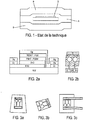
- FIG. 1 A block diagram of a device resting on a plastic support and encapsulated by lamination of a barrier film is shown in Figure figure 1 .
- the gases from the atmosphere from which it is sought to protect the device can reach the device according to orthogonal permeation processes (perpendicular to the plane of the module and thus through barrier films) and according to lateral permeation process (in the plane of the module: through the adhesive from its peripheral free edge, and at the interfaces between the adhesive and the barrier structure).
- the protection of the device against lateral permeation is mainly ensured by the adhesive which constitutes the most permeable link of the structure.
- the adhesives preferably used are of the epoxy family, widely known to the general public and to those skilled in the art and are combined with moisture absorbers of the metal oxide type.
- epoxy adhesives also have drawbacks in the field of the invention due to their poor resistance to aging outdoors, due to photochemical attacks that light, oxygen and humidity can cause on their chemical structure.
- the invention aims to provide an adhesive capable of improving the lateral protection against gas permeation of flexible electronic devices encapsulated between two protective sheets or between two structures. multilayer barriers, while maintaining their flexibility and integrity during the encapasulation process and over time.
- the invention uses an adhesive formulation allowing a significant improvement in the lateral permeation properties of the encapsulation of an electronic device while offering the possibility of preserving as much as possible the flexibility properties of this device when it is provided with it.
- (meth) acrylic as used relates to any type of acrylic or methacrylic monomers.
- PMMA refers to homo- and copolymers of methyl methacrylate (MMA), the weight ratio of MMA in PMMA being at least 50%, preferably at least 55%, so more preferably at least 70% by weight for the MMA copolymer.
- MMA methyl methacrylate
- the term "monomer” as used refers to a single molecule, exhibiting a single repeating unit, with a molar mass of less than 300 g / mole, which can undergo polymerization.
- oligomer refers to a molecule with a molar mass greater than 300 g / mole, and which can undergo polymerization.
- polymerization refers to the process of converting a monomer or a mixture of monomers into a polymer.
- thermoplastic polymer refers to a polymer which turns into a liquid or becomes more liquid or less viscous when heated and which can take on new forms by the application of heat and pressure.
- thermosetting polymer refers to a prepolymer in a soft, solid or viscous state. which irreversibly transforms into an insoluble and infusible polymer network by crosslinking.
- crosslinking refers to the chemical process allowing molecules to bind together to form a three-dimensional network.
- initiator or "initiator” as used refers to a chemical species which reacts with a monomer to form an intermediate compound capable of successfully binding a large number of other monomers or other intermediate compounds. to form a polymeric compound. If the monomers have a sufficient number of reactive functions, for example if the average functionality of at least part of the monomers is greater than or equal to two, a crosslinked system can be obtained.
- the term “flexible” is to be understood as the ability of a material, due to its intrinsic properties and / or its low thickness, to flex, bend or bend easily.
- the adhesive layer used and the protective sheet may advantageously have, by virtue of their mechanical properties (low rigidity) and / or their thickness, a flexibility equal to or greater than that of the flexible substrate on which the flexible electronic element is deposited (possibly organic), typically a PET substrate 10 to 250 microns thick.
- the substrate, the adhesive layer used and the protective sheet can be deformed to have a radius of curvature of 10 cm without undergoing structural or functional degradation.
- extra-fine particles is to be understood as particles having in at least one direction, an average length less than or equal to 20 microns, preferably 10 microns, preferably 6 microns, preferably 1 micron, of preferably at 300 nm, preferably at 100 nm; being greater than or equal to 10 nm, preferably 30 nm. These particles can be in different shapes (spherical, cubic, parallelepiped, lamellar).
- nanoparticles comprise nanoparticles having a lamellar structure defining layers of a size less than or equal to 20 microns, preferably less than or equal to 10 microns, preferably less than or equal to 6 microns; and / or are spherical and have an average diameter less than or equal to 1 micron, preferably less than or equal to 300 nm, preferably less than or equal to 100 nm, preferably less than or equal to 60 nm.
- the dimensions of the extra-fine particles such as their diameters or lengths, can be established by electron microscopy or light scattering.
- ambient temperature designates the temperature of 25 °, unless it is explicitly stated in its use in the text which it designates of a different temperature.
- flexible electronic assembly is understood to mean an assembly including a flexible electronic device comprising an electronic element (of the electronic polymer type or (opto) electronic device comprising thin layers) optionally mounted on a flexible substrate, and protected from permeation to gases by at least one protective sheet against the permemation of gases.
- the flexible assembly can be deformed to have a radius of curvature of 10 cm without undergoing structural or functional degradation.
- compatible with the substrate or the electronic device is understood to mean a compound, monomer, adhesive, adhesive precursor which does not adversely affect or only slightly (less than 20%, preferably 10%, preferably 5%). , the operation of the device (for example the conversion efficiency for a photovoltaic cell).
- Flexible devices encapsulable using the encapsulation method according to the invention include organic photovoltaic devices.
- the figure 1 shows a known configuration of flexible encapsulation of a flexible electronic device or component, comprising two barrier films B, positioned on either side of component D, and an adhesive A making it possible to hold the barrier films on the component and of the 'encapsulate.
- the term “encapsulation scheme” refers to all of the elements deployed to isolate the component from the oxygen and water present in the environment, generally in the form of vapor.
- the adhesive obtained following the polymerization of the precursor according to the invention can be used to secure to the flexible electronic device protective sheets which are particularly suitable for flexible electronic devices.
- This type of sheet is a multilayer structure comprising a substrate and a first stack of a layer of SiO 2 and a layer of material of SiO x N y H z type arranged between the substrate and the layer of SiO 2 such that described in the request for patent WO2013 / 045393 , Where WO2013 / 140101 .
- the adhesive precursor formulations according to the invention are liquid or low viscous, non-solvent, polymerizable at low temperature (for example at room temperature between 15 and 35 ° C), comprise oligomers with reactive double bonds or monomers and polymers. oligomers with reactive double bonds of (meth) acrylic type and are capable of accommodating fillers and additives that are easily dispersible and make it possible to radically modify the mechanical, adhesive and permeation characteristics of the barrier adhesive layer which will ultimately be present in the structure protecting the device.
- the adhesive precursor formulations according to the invention retain the advantage of being liquid at the time of application to the device to be encapsulated, but their polymerizable functions are not of an epoxy chemical nature.
- the monomers / oligomers used in these formulations can comprise functions of a chemical nature (meth) acrylic, and exhibit a high resistance to aging in the exterior while making it possible and easy to modify their rheological (or flow) properties, as well as their adhesive or permeation properties by adding additives therein and / or by choosing the constituent monomers / oligomers of the adhesive precursor.
- the adhesive precursor formulations according to the invention have the advantage of being liquid before polymerization while leading, after polymerization, to adhesives which are resistant to aging on the outside, respecting the flexibility of the electronic device which they encapsulate and also having interesting properties for indoor applications (oled, detectors).
- oligomers with reactive double bonds ensures a "soft" polymerization of the precursor, avoiding or limiting the phenomenon of withdrawal of the adhesive at the end of this. phenomenon, which contributes to its performance in terms of permeability to water and oxygen.
- the formulations according to the invention can easily be adjusted in terms of flow behavior (rheology), including one of the main properties is viscosity and its evolution as a function of the shear rate.
- rheology flow behavior
- the possibility of formulating the adhesives to adapt their rheology to the mode of deposition on the device is of paramount importance for the high speed industrial applications of these adhesives. They can also be adjusted in terms of photochemical resistance according to the intended field of application thanks to the various possible combinations of monomers and oligomers.
- the formulations according to the invention can also accommodate within them additives and fillers which can make it possible to further improve their performance in terms of adhesion, mechanical properties and permeability to water and to oxygen.
- hydrophobic tackifying resins allowing an improvement in adhesion without degrading the permeability performance, can easily be incorporated within the formulations of the invention.
- fillers which are active (called “getters” or water scavengers) or passive (without water scavenging effect) are easily dispersible in the liquid formulations of the invention and can also be combined within them.
- Another advantage of these formulations is that, surprisingly, they lead to adhesives with improved side barrier properties compared to products of the prior art, which are not or which are very little dependent on the thickness, in a thickness range where the performances of the adhesives of the prior art are very dependent on the thickness, as expected, according to aspect 2 of the above list on critical aspects.
- This makes it possible to envisage a good conformation of the devices to be protected, by increasing the thickness of the adhesive layer, without this inevitably leading to a degradation of the permeability as for the adhesives of the prior art.
- an adhesive precursor developed, in accordance with the invention is composed of a mixture of (meth) acrylic monomers, oligomers with reactive double bonds functionalized with (meth) acrylic groups and of photoinitiators.
- the oligomers can comprise a chemical structure based on urethanes, polyamides, polyesters or epoxies and they are functionalized with at least one (meth) acrylic group.
- Photoinitiators can, for example, be formed from a mixture of 1-hydroxy-cyclohexyl-phenyl-ketone and ethyl - 2,4,6 - trimethyl-benzoyl-phenyl-phosphinate.
- photoinitiators make it possible to cause polymerization of the acrylic groups via the absorption of rays of light of the UVA, violet and blue type ( ⁇ 425 nm wavelength).
- the adhesive precursor formulations are liquid or low viscous at room temperature and do not include solvents, the latter aspect being valuable for the compatibility of the adhesive precursor formulation with the device.
- the liquid nature of the adhesives allows easy modification of the formulation with additives, tackifying resins, for example.
- the deposition of the adhesive precursors can be done by several methods because the viscosity can be varied by the addition of additives or by controlling the temperature of the adhesive.
- the adhesive precursors are deposited on a transparent barrier film and / or directly on an electronic device to be encapsulated.
- the device and barrier film are laminated so that the adhesive precursor is located between the device and the barrier film.
- the assembly is then illuminated under a lamp which produces wavelengths including those between 300nm and 425nm.
- the substrate supporting the device and disposed between the adhesive and the lamp is transparent to this range of wavelengths.
- the adhesive can reach its maximum level of polymerization after approximately 5 seconds with a medium pressure mercury lamp, with a broad spectrum or with LEDs (light emitting diodes). ) which have light emission at 400nm wavelength.
- the substrate is not transparent with respect to the polymerization wavelength of the adhesive, to encapsulate the front face, and to polymerize the adhesive, it suffices to turn the device upside down. It is then essential that the barrier film be transparent in the wavelength range considered.
- the water vapor barrier properties were characterized by an optical calcium test. This test uses a metallic calcium deposit on a polymeric substrate that simulates a device. This calcium test piece is then laminated between two transparent barrier films and the adhesive to obtain the following structure: barrier film - adhesive - calcium test tube - adhesive - barrier film.
- the adhesive precursor is cured after lamination and aged at 65 ° C and 85% relative humidity. Pictures are taken periodically to look at the level of calcium breakdown. Calcium, in fact, reacts with water quickly to produce calcium hydroxide which is transparent. Thus, the change in transparency of the calcium in the images allows the calculation of the level of water which has passed through the barrier films and the water permeation by the edges of the sample is calculated by the decrease in the size of the deposit of calcium which is gradually converted into calcium hydroxide.
- compositions of preferred examples, F18 and S3 are Compositions of preferred examples, F18 and S3:
- hydrophobic tackifying resin further decreases the water permeation.
- tackifying resin improves adhesion to multilayer barrier structures.
- An Oike barrier film consists of the multilayer next: 25 micron PET / gas barrier layer / Adhesive / gas barrier layer / PET.
- the gas barrier layer is a thin inorganic layer with a thickness of the order of 100 nm.
- the film used is known under the reference VX-25T-2PO sold by the company Oike.
- the WVTR is 3.10-4 gm -2 .j -1 according to the data sheet for this product.
- adhesive precursors in accordance with the invention can be prepared by a person skilled in the art specializing in the preparation of adhesive precursors by first proceeding with a selection of (metha) crylic monomers compatible with the device. electronic to encapsulate.
- the formulation to be polymerized using ultraviolet (UV) irradiation must take into account the chemical compatibility with the device to be protected
- UV ultraviolet
- the monomers in fact, present the greatest risk of deterioration of the device, since they are small molecules which can act as solvents or react chemically with the different layers of the device and thus affect its performance. To ensure that this is not the case, preliminary tests for chemical compatibility can be carried out.
- the OPV cells tested were of inverted architecture and had the following structure: polyethylene terephatalate (PET) film - tin and indium oxide layer (aglais acronym ITO) - zinc oxide nanoparticle layer (Zn0) - layer active of P3HT: PCBM -PEDOT layer: PSS - conductive layer of silver deposited by evaporation.
- PCBM means an active layer based on a bulk heterojunction consisting of a mixture of poly (3-hexylthiophene) and the methyl ester of phenyl C61 butyric acid.
- PEDOT: PSS is a hole transport layer consisting of a blend of poly (3,4-ethylene dioxythiophene) and polystyrene sulfonate. The monomers were deposited by "spin-coating" on the rear part of the cell, which implies that they have come into contact with the layers of silver and PEDOT: PSS; the possible contact with other layers via lateral penetration cannot however be ruled out
- Formulation F5 was the first to show some adhesion, although this was not sufficient to measure it by a “T” peel test.
- Formulations F6 and F10 also showed some adhesion, but this was at the limit of what could be measured using the "T” peel test. They also exhibited a peeling behavior of the “adhesion-slip” or “stick-slip” type.
- Formulation F9 comprises almost 90% of an oligomer whose homopolymer is at low glass transition temperature or Tg (CN131B), the adhesion promoter SR9050, used only in formulation F15, then a different ratio of the two photoinitiators.
- This formulation also exhibited poor adhesion to the limit of detection by the “T” peel test and behavior of the “stick-slip” type.
- New modifications have been attempted in order to improve the adhesion by the use of oligomers and monomers supposed to promote this type of adhesion, but no good results were obtained before the F13 formulation which showed a measurable adhesion by the "T” peel test; this formulation, however, also exhibited marked behavior of the “stick-slip” type.
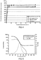
- the F18 formulation exhibited a strong inhibition of the polymerization by oxygen requiring the performance of the UV conversion step between two sheets of plastic substrate, when the conversion is carried out outside a controlled atmosphere glove box (conversions in air atmosphere). This mode of conversion between two substrates is also preferred since it corresponds to what is done during the device encapsulation processes. Tests were carried out using either PET plastic substrates (50 microns thick) or Oike VX 25T-2PO barrier films, since these two plastic films have different light transmission spectra. Both types of lamps (low pressure mercury) and LED have also been tested. Regardless of the conversion process used, the conversion of formulation F18 was carried out in a short time in accordance with the figure 4 . To ensure that all samples converted correctly, exposure times of 30 seconds were used.
- Another adhesive was formulated using a selection procedure similar to that leading to formulation F18.
- the aim was to improve the adhesion of the F18 formulation. This was achieved by replacing the two oligomers of formulation F18 with a different composition of oligomer and monomer. The monomer has also been tested for chemical compatibility with OPV cells.
- Norsolene S95 non-reactive aliphatic tackifying resin was added to the formulation to further promote adhesion.
- S3 of formulation presented in the table above exhibited an adhesion strength of 3.01 N / cm in the "T" peel test on PET, which is significantly greater than 1. , 32 N / cm of formulation F18.
- the liquid adhesive of the invention comprises at least one unsaturated oligomer and at least one photoinitiator.
- the unsaturated oligomer is such that it has at least one reactive (polymerizable) group per molecule chosen from (meth) acryl functions.
- the monomers and oligomers useful for the invention are chosen from mono, di, tri or polyfunctional molecules having a molecular mass of between 30 and 30,000 daltons.
- alcohol (meth) acrylate functions such as: ethanol, propanol, isopropanol, butanol, isobutanol, hexanol, methyl pentanol, iso-octanol, n-octanol, 2-ethylhexanol, iso-decanol, n-decanol, lauryl alcohol, tridecyl alcohol, tetradecyl alcohol, cetyl alcohol, stearyl alcohol behenyl alcohol, cyclohexyl alcohol, 3,3,5-trimethyl cyclohexyl alcohol, cyclic trimethylolpropane formal, 2-phenoxy ethanol, nonyl phenol, isobornol and (metha) cryl esters of diols and polyols such as ethylene glycol, propylene glycol, 1 , 3-propanediol, 1,3-
- (meth) acrylates glycidyl methacrylate diacrylate, glycidyl mono, di or poly (meth) acrylate, glycidyl methacrylate diacrylate, glicydil di (meth) acrylate, mono, di or poly (meth) acrylates of allyl alcohol, or of alkoxylated allyl alcohol, mono, di or poly (meth) acrylate of vinyl alcohol mono, di or poly (meth) acrylates, hydroxyalkyl (meth) acrylates, trimethylol propane triacrylate ethoxylate (Ethoxylated TMPTA), glycerol tri (meth) acrylate or di (meth) acrylate, trimethylol propane tri (meth) acrylate (TMPTA or TMPTMA), hexanediol di (meth) acrylate, bisphenol A diacrylate, phenoxy ethyl (meth) acrylate,
- epoxy (meth) acrylates such as those derived from an ether selected from the group consisting of bisphenol A diglycidyl ether 1, 4-butanediol diglycidyl ether or polypropylene glycol diglycidyl ether, urethane (meth) acrylates such as those derived from an isocyanate selected from the group consisting of toluene diisocyanate, methylene diphenyl diisocyanate, methylene diphenyl hydrogenated di-isocyanate, isophorone diisocyanate, hexamethylene diisocyanate, trimethyl hexamethylene diisocyanate in combination with an active hydrogen compound selected from the group consisting of a polycarbonate, polyetherol or polyether; hydroxyalkyl (meth) acrylate, such as hydroxyethyl (meth) acrylate or polycaprolactone (meth) acrylate; and polyester
- the oligomers can also be high functionality dendritic (meth) acrylates such as those sold by Sartomer (Arkema group), such as CN2301, CN2302, CN2303 and CN2304.
- They may also be multifunctional (meth) acrylic (meth) acrylated oligomers derived from glycidyl (meth) acrylate, such as those derived from partial or total acrylation with acid.
- the glass transition temperature (Tg) of the irradiation crosslinkable polymer is preferably in the range between -60 and + 10 ° C, more particularly in the range between -60 and 0 ° C, or between -55 ° C and -10 ° C, and more preferably between -55 ° C and -20 ° C.
- the glass transition temperature can be determined by usual methods, such as differential thermal analysis or differential scanning calorimetry (DSC).
- inverted “S” or “S” curves (depending on the convention used) during ascending scans in temperature, at constant scanning speed (generally at 10 ° C / min) which provide thermograms or DSC curves where, most often, the heat flow is represented as a function of the temperature ; it is also known to those skilled in the art that these inverted “S” or “S” have three inflection points (the first at the lowest temperature, corresponding to the start of the glass transition, the intermediate point, and the last at the highest temperature, corresponding to the end of the glass transition).
- the values given above for the Tg correspond to those obtained from the first inflection point (lowest temperature, in a temperature rise sweep) of the Heat Flow curve as a function of temperature.
- the equation referred to as the Fox Equation enables those skilled in the art to identify, beforehand, copolymers in the corresponding Tg range, and to prepare them specifically by suitably varying the nature and amount of monomers. According to Fox ( TG Fox, Bull. Am. Phys. Soc. 1956 [Ser. II] 1, page 123 , and in accordance with Ullmann's Encycloischen Chemie, vol.
- Tg values for the homopolymers of the majority of the monomers are known and listed, for example, in the Ullmann's Encyclopedia of Industrial Chemistry, vol. A21, page 169, 5th edition, VCH Weinheim, 1992 ; other sources of homopolymer glass transition temperatures can also be found in J. Brandrup, EH Immergut, Polymer Handbook, 1st edition, J. Wiley, New York 1966 , 2nd edition, J. Wiley, New York 1975 , and 3rd edition, J. Wiley, New York 1989 ).
- This Fox equation can only be used as a guide to start a formulation, especially since the adhesives according to the invention are not necessarily in a situation of low crosslinking rate, but rather on the contrary, in a situation of low crosslinking rate. relatively high crosslinking.
- UV curing acrylate adhesives have all been supplied as monomers, oligomers or mixtures of monomers, oligomers and additives. It was therefore necessary to prepare the formulations before use, by mixing these materials in the appropriate ratios with photoinitiators.
- the solutions were mixed in bottles or glass vials, by magnetic stirring.
- the components were measured by mass and added directly to the main solution. This has been the case because of the tendency for many monomers and oligomers to leave a quantity of residue on the containers and measuring devices with which they were in contact.
- Very high viscosity oligomers have always been added first using a spatula, followed by the remaining monomers and oligomers whose precision was obtained by dropwise addition.
- the solution could always be completely mixed, it could be at least partially before the addition of the photoinitiators. After the photoinitiators were added, the solutions could be completely mixed by magnetic stirring. Several formulations were too high a viscosity to be stirred.
- the magnetic stir plate was heated to 60 ° C to reduce the viscosity of the solution and allow thorough mixing. This heating technique was also used when these solutions had to be deposited with a pipette, to facilitate handling. The absence of changes in the refractive index and particles made it possible to visually verify the homogenization of the mixture.
- the substrates were first cut to the approximate size of the final sample. As with lamination of PSAs, it can be difficult to achieve perfect alignment during the operation; it was therefore considered simpler and more precise to cut the sample to its correct dimensions after rolling.
- the substrates were surface treated as desired (solvent rinsing, solvent sonication, corona treatment), then dried in a vacuum study at 80 ° C / 1-5mbar, for two days, followed by cooling to 30 ° C, always under vacuum.
- the substrates were then quickly placed in the glove box. then coated with adhesive on the inside of the box, as previously described.
- the article to be encapsulated was immediately laminated to a substrate manually coated with adhesive. A second adhesive coated substrate was then laminated on top, again manually.
- the laminated sample was subsequently cured, as required by the adhesive, as explained below. Then, the sample was inverted and cured for a second full cycle, to ensure proper curing of the lower areas of the encapsulated object.
- This class of adhesive also requires the additional step of UV light curing between the substrates.
- Curing of the UV curing (meth) acrylic adhesives was carried out using two different lamps. Cure parameters were confirmed for each lamp separately, but, when validated, the two lamps were used interchangeably and considered to provide equivalent cure.
- This lamp produces a broad spectrum of wavelengths, ranging from approximately 200 to 600 nm. Although the intensity of this lamp cannot be adjusted, decreasing the distance between the latter and the sample increases the intensity on it.
- the second UV lamp using an LED light emitting diode source, was placed inside an inert atmosphere glove box.
- This lamp DELOLUX 20/400, produced a narrow spectrum of wavelengths, with a peak at ⁇ 400nm.
- the structure supporting this lamp did not allow to change the distance between it and the sample, but the control unit allowed the adjustment of the power supplied by the lamp (and therefore, its intensity).
- BASF Lucirin TPO-L is a liquid photoinitiator, activated by longer wavelengths of light than Irgacure 184, consisting of ethyl-2,4,6-trimethylbenzoylphenylphosphinate.
- photoinitiators 2-hydroxy-2-methyl-1-phenyl-propan-1-one, 2,4,6-trimethylbenzoyl-diphenyl-phosphineoxide, 1-hydroxy-cyclohexyl-phenyl-ketone, bis (2,6- dimethoxybenzoyl) -2,4,4-trimethyl-pentyl phosphine oxide, 1- [4- (2-hydroxyethoxy) -phenyl] -2-hydroxy-2-methyl-1-propan-1-one, 2,2 -dimethoxy-1,2-diphenylethan-1-one and 2-methyl-1 [4- (methylthio) phenyl] -2-morpholinopropan-1-one, are nonlimiting examples of said at least one photoinitiator.
- said at least one photoinitiator is reactive in the UV and visible spectra. In certain other embodiments, said at least one photoinitiator, activated by light in the visible spectrum, allows curing when light passes through glass or other UV filtering protective layers.
- Phenylphosphine oxides such as Irgacure 184, manufactured by Ciba, and today, by BASF, and Lucirine TPO, manufactured by BASF, are non-limiting examples of such photoinitiators.
- Nanoparticles capable of having an effect of reducing water permeation can be incorporated the adhesive precursor, in a content preferably between 3 and 20% by weight.
- These nanoparticles comprise extra-fine particles having a lamellar structure defining layers of a size less than or equal to 20 microns, preferably less than or equal to 10 microns, preferably less than or equal to 6 microns, such as phyllosilicates, preferably Cloisite 10A and / or Cloisite 15A; and / or are substantially spherical and have an average diameter less than or equal to 1 micron, preferably less than or equal to 300 nm, preferably less than or equal to 100 nm, preferably less than or equal to 60 nm such as natural synthetic zeolites and / or artificial, preferably zeolites of Linde Type L (LTL) structure.
- LTL Linde Type L
- nanoparticles can also comprise extra-fine particles of an absorbent material, such as crosslinked sodium polyacrylate particles, and for example have sizes less than 100 microns, preferably 10 microns, preferably 1 micron, preferably less than 100 microns. 500 nm, preferably 50 nm.
- an absorbent material such as crosslinked sodium polyacrylate particles
- the figure 5 represents the DMTA curve of F18, in a test carried out with a rising temperature ramp of 3 ° C / min, at a fixed frequency of 1 Hz and at a fixed maximum strain of 0.1%.
- the adhesive exhibited typical behavior of a crosslinked polymer, with a clear glass transition and a rubbery plateau showing a slight and gradual increase in modulus of storage above Tg.
- figure 5 exhibits the rapid drop of the loss modulus, below the detection limit of the equipment, due to the rise to higher temperatures.
- F18 is sufficiently flexible, but increasing its stiffness at colder temperatures raises concerns for its use in the current encapsulation of OPV devices, which can be exposed to winter temperatures in the cold. 'outside. A slightly softer version of this adhesive may be required if the final product is subjected to colder weather conditions.
- Adhesive Pic E "DMTA F18 -20 ° C
- Samples were also prepared using barrier films treated by corona effect, for both adhesives.
- F18 and S3 are mainly characterized by interfacial permeation, it is important to improve the interface.
- the corona effect treatments were intended to improve the adhesion of the two adhesives, and to limit lateral permeation in the optical calcium tests.
- the relationship between the bond strength and the lateral water permeation rate of the corona-treated sample coincides with the trend noted for the samples not treated by this process, as can be seen in the figure 9BIS .
- the assays all used structurally inverted OPV cells, and made in the same way.
- the Figure 2 illustrates the exact architecture of the cells with the image of a complete device before encapsulation.
- the cells consisted of a 17mm x 25mm x 175 ⁇ m PET substrate, with a transparent conductive oxide (acronym TCO) on one surface. Gold coated chromium pads were then deposited sequentially by physical vapor deposition by evaporation, at the ends of the substrates, to allow contact of the electrodes during the measurement of the completed cell.
- the electron transport layer (acronym in English ETL) consisted of nanoparticles of zinc oxide coated by centrifugal deposition in an ambient atmosphere, from a suspension in ethanol.
- the active layer exhibited a heterojunction structure of poly (3-hexylthiopene) (P3HT), as absorber, and phenyl C 61 butyric acid methyl ester (PCBM), as electron acceptor.
- P3HT poly (3-hexylthiopene)
- PCBM phenyl C 61 butyric acid methyl ester
- This active layer was applied by centrifugal deposition on the ETL, from a solution in dichlorobenzene, inside a glove box in an inert atmosphere.
- the hole transport layer (acronym for HTL), consisting of poly (3,4-ethylenedioxythiophene) mixed with poly (styrene sulfonate) (PEDOT: PSS), was deposited by centrifugation on the active layer in air , from an aqueous solution.
- a lower silver electrode was finally applied by physical vapor deposition by evaporation, so as to create two cells per substrate.
- the cells were then measured by J-V characterization and stored inside a glove box in an inert atmosphere. Only cells showing good performance in J-V characterization were used in the encapsulation studies.
- Accelerated aging was carried out according to the ISOS-D-3 standard, at a temperature of 65 ° C and a relative humidity of 85%, without lighting.
- One solution to the problem was to completely encapsulate the cells without lead wires or electrical connections.
- the barrier film can be opened by cutting it over the electrodes.
- 3M Charge-Collecting Solar Tape 3307 interconnect tape was placed over the electrodes prior to encapsulation. This destructive process means that each device can only be measured once after encapsulation, which eliminates the possibility of subsequently measuring the encapsulated cells and tracking the aging of a single cell at predetermined time intervals. This scheme will henceforth be referred to as "direct" encapsulation.
- Another solution to avoiding lead wires is to leave the electrodes unencapsulated.
- This scheme allows for easy and repeated measurement of cells, but also to less monitor the distances between the edge of the encapsulation and the cell. It can also lead to the exposure of the hygroscopic PEDOT: PSS layer to air, in certain regions outside the encapsulation, providing a potential path for water vapor permeation.
- This scheme will henceforth be referred to as "open electrode" encapsulation.
- a final encapsulation scheme used in the present invention, consists of a 3M Charge-Collecting Solar Tape 3307 interconnection tape, used to connect the two cells in parallel, then to exit the encapsulation.
- This diagram ensures good control of the distances between the edge of the encapsulation and the cell, and allows repeated and easy measurement of the cells, even if this causes a problem with the output of electrical connections from the encapsulation, mentioned previously.
- This diagram, presented on figure 3c will be referred to as "tape" encapsulation.
- Accelerated humidity aging tests were carried out at 65 ° C and 85% relative humidity, regardless of the type of sample. These conditions were selected because they correspond to the ISOS-D-3 standard, which uses the same conditions as those described above, for moist heat aging of organic photovoltaic devices, without lighting. These conditions were produced in a humid chamber, using either Dycometal CM-25/48 or Clima Temperatur Systeme C-40/100. Samples were placed on wire rack shelves in both chambers.
Landscapes
- Physics & Mathematics (AREA)
- Optics & Photonics (AREA)
- Electromagnetism (AREA)
- Chemical & Material Sciences (AREA)
- Organic Chemistry (AREA)
- Adhesives Or Adhesive Processes (AREA)
- Adhesive Tapes (AREA)
- Encapsulation Of And Coatings For Semiconductor Or Solid State Devices (AREA)
- Application Of Or Painting With Fluid Materials (AREA)
Claims (7)
- Verfahren zum Verkapseln einer flexiblen elektronischen Vorrichtung mit wenigstens einer flexiblen Schutzfolie gegen die orthogonale Gaspermeation durch einen schützenden Klebstoff gegen die seitliche Gaspermeation, wobei das Verfahren umfasst:- einen Schritt des Aufbringens einer Schicht eines polymerisierbaren Präkursors des schützenden Klebstoffs gegen die seitliche Gaspermeation auf die Oberfläche der Vorrichtung und/oder auf die Oberfläche der flexiblen Gasschutzfolie, wobei der Klebstoffpräkursor Oligomere mit reaktiven Doppelbindungen eines (Meth)acryltyps und einen Polymerisationsinitiator umfasst,- dann einen Schritt der Polymerisation des aufgebrachten Klebstoffpräkursors, während er sich zwischen der Vorrichtung und der Gasschutzfolie befindet, so dass er den Klebstoff bildet, der die Schutzfolie mit der Vorrichtung verbindet, während die Vorrichtung gleichzeitig vor seitlicher Gaspermeation geschützt wird.
- Verfahren nach Anspruch 1, wobei der Klebstoffpräkursor in einem nicht polymerisierten Zustand während des Aufbringens auf die Oberfläche der Vorrichtung und/oder auf die Oberfläche der flexiblen Gasschutzfolie bei einer Schergeschwindigkeit von 1 s-1 eine dynamische Viskosität von 10-3 bis 101 Pa·s, vorzugsweise bei einer Schergeschwindigkeit von 1 s-1 von 10 mPa·s bis 100.000 mPa·s, vorteilhafterweise bei einer Schergeschwindigkeit von 1 s-1 von 50 mPa·s bis 75.000 mPa·s aufweist.
- Verfahren nach Anspruch 1 oder 2, wobei der Klebstoffpräkursor durch UV-Strahlung polymerisierbar ist.
- Verfahren nach einem der vorhergehenden Ansprüche, wobei die Schicht des Klebstoffpräkursors in dem nicht polymerisierten Zustand in einer vorbestimmten Dicke aufgebracht wird, wodurch es ermöglicht wird, den nach der Polymerisation gebildeten Klebstoff mit einer Dicke kleiner als oder gleich 3000 Mikrometer, vorzugsweise kleiner als oder gleich 150 Mikrometer, zu versehen.
- Verfahren nach einem der vorhergehenden Ansprüche, wobei der Klebstoffpräkursor (Meth)acrylmonomere, vorzugsweise ein ethoxyliertes Alkylphenolacrylat, umfasst und die Oligomere mit (Meth)acrylgruppen funktionalisiert sind.
- Verfahren nach einem der vorhergehenden Ansprüche, wobei das Oligomer mit reaktiven Doppelbindungen aus der Familie der aromatischen Epoxy(meth)acrylate, difunktionellen aliphatischen (Meth)acrylate oder einer Mischung davon ausgewählt ist oder wobei das Oligomer mit reaktiven Doppelbindungen ein Oligomer ist, das ein aliphatisches Urethandiacrylat und 10 % 2-(2-Ethoxyethoxy)ethylacrylat umfasst.
- Verfahren nach einem der vorhergehenden Ansprüche, wobei der Polymerisationsinitiator aus Folgenden ausgewählt ist: 2-Hydroxy-2-methyl-1-phenylpropan-1-on, 2,4,6-Trimethylbenzoyldiphenylphosphinoxid, 1-Hydroxycyclohexylphenylketon, bis(2,6-Dimethoxybenzoyl)-2,4,4-trimethylpentylphosphinoxid, 1-[4-(2-Hydroxyethoxy)phenyl]-2-hydroxy-2-methyl-1-propan-1-on, 2,2-Dimethoxy-1,2-diphenylethan-1-on und 2-Methyl-1[4-(methylthio)phenyl]-2-morpholinopropan-1-on.
Applications Claiming Priority (2)
| Application Number | Priority Date | Filing Date | Title |
|---|---|---|---|
| FR1559456A FR3041971B1 (fr) | 2015-10-05 | 2015-10-05 | Adhesif acrylique dont le precurseur est applique sous forme liquide et reticule uv, pour l'encapsulation de dispositifs electroniques flexibles, ameliorant la protection contre la permeabilite aux gaz. |
| PCT/FR2016/052543 WO2017060609A1 (fr) | 2015-10-05 | 2016-10-04 | Adhésif dont le précurseur est appliqué sous forme liquide et polymérisé uv, pour l'encapsulation de dispositifs électroniques flexibles, améliorant la protection contre la perméabilité aux gaz |
Publications (2)
| Publication Number | Publication Date |
|---|---|
| EP3360174A1 EP3360174A1 (de) | 2018-08-15 |
| EP3360174B1 true EP3360174B1 (de) | 2021-12-08 |
Family
ID=55299599
Family Applications (1)
| Application Number | Title | Priority Date | Filing Date |
|---|---|---|---|
| EP16788170.5A Active EP3360174B1 (de) | 2015-10-05 | 2016-10-04 | Klebstoff mit flüssig aufgetragenem und uv-polymerisiertem vorläufer zur verkapselung von flexiblen elektronischen vorrichtungen, verbesserung des schutzes gegen gasdurchlässigkeit |
Country Status (3)
| Country | Link |
|---|---|
| EP (1) | EP3360174B1 (de) |
| FR (1) | FR3041971B1 (de) |
| WO (1) | WO2017060609A1 (de) |
Families Citing this family (2)
| Publication number | Priority date | Publication date | Assignee | Title |
|---|---|---|---|---|
| KR102881522B1 (ko) * | 2020-01-29 | 2025-11-07 | 삼성디스플레이 주식회사 | 표시 장치 및 이의 제조 방법 |
| CN115558443A (zh) * | 2022-10-14 | 2023-01-03 | 合肥德瑞格光电科技有限公司 | 一种偏光片用uv光固化压敏胶及其制备方法 |
Family Cites Families (6)
| Publication number | Priority date | Publication date | Assignee | Title |
|---|---|---|---|---|
| FR2501213A1 (fr) * | 1981-03-05 | 1982-09-10 | Altulor Sa | Prepolymere acrylique et son application a l'encapsulation de photopiles |
| JP5263849B2 (ja) * | 2008-04-09 | 2013-08-14 | エージェンシー フォー サイエンス,テクノロジー アンド リサーチ | 酸素及び/又は水分に敏感な電子デバイスをカプセル封じするための多層膜 |
| CN101993513B (zh) * | 2009-08-17 | 2012-12-12 | 财团法人工业技术研究院 | 封装材料组合物及封装材料的制造方法 |
| WO2011138630A1 (en) * | 2010-05-03 | 2011-11-10 | Arkema France | Uv curable encapsulant |
| EP2882761B1 (de) * | 2012-08-08 | 2017-04-19 | 3M Innovative Properties Company | Harnstoff(multi)-urethan(meth)acrylat-silanzusammensetzungen und artikel damit |
| KR101600653B1 (ko) * | 2012-12-26 | 2016-03-07 | 제일모직주식회사 | 봉지용 조성물, 이를 포함하는 장벽층 및 이를 포함하는 봉지화된 장치 |
-
2015
- 2015-10-05 FR FR1559456A patent/FR3041971B1/fr active Active
-
2016
- 2016-10-04 EP EP16788170.5A patent/EP3360174B1/de active Active
- 2016-10-04 WO PCT/FR2016/052543 patent/WO2017060609A1/fr not_active Ceased
Non-Patent Citations (1)
| Title |
|---|
| None * |
Also Published As
| Publication number | Publication date |
|---|---|
| FR3041971A1 (fr) | 2017-04-07 |
| WO2017060609A1 (fr) | 2017-04-13 |
| EP3360174A1 (de) | 2018-08-15 |
| FR3041971B1 (fr) | 2021-12-03 |
Similar Documents
| Publication | Publication Date | Title |
|---|---|---|
| EP3030530B1 (de) | Substrat mit einer funktionellen beschichtung und einer temporären schutzschicht | |
| JP5216724B2 (ja) | ガスバリアフィルムおよびデバイス | |
| TWI602707B (zh) | Gas barrier film laminate, method of manufacturing the same, and electronic device | |
| EP2557137A1 (de) | Kugelförmiges phosphor, dichtungsmaterial für eine wellenlängenumwandelnde solarbatterie, solarbatteriemodul und herstellungsverfahren dafür | |
| JP6382722B2 (ja) | 光電池のバックシートのための放射線硬化性接着剤組成物 | |
| JP5334900B2 (ja) | ガスバリアフィルムおよびデバイス | |
| JP2015531704A (ja) | バリアアセンブリの製造方法 | |
| CN109476138B (zh) | 阻气膜及太阳能电池以及阻气膜的制造方法 | |
| CN101908572A (zh) | 波长转换片的光学特性控制方法、波长转换片的制造方法、碲化镉系太阳电池用波长转换片及碲化镉系太阳电池 | |
| TW201219462A (en) | Fluorescence conversion solar cell-production in a sheet casting process | |
| EP3360174B1 (de) | Klebstoff mit flüssig aufgetragenem und uv-polymerisiertem vorläufer zur verkapselung von flexiblen elektronischen vorrichtungen, verbesserung des schutzes gegen gasdurchlässigkeit | |
| CN104812869A (zh) | 波长转换聚合物膜 | |
| EP3853910B1 (de) | Flexibles laminat aus fotovoltaischen zellen und zugehöriges herstellungsverfahren | |
| FR3041970B1 (fr) | Encapsulation de dispositifs electroniques flexibles, avec un adhesif incluant des particules extra-fines ameliorant la protection contre la permeabilite aux gaz | |
| CN115103887B (zh) | 带脱模薄膜的粘合片及其制造方法 | |
| CN105684163A (zh) | 波长转换型封装材料组合物、波长转换型封装材料层及使用其的太阳能电池模组 | |
| KR20170090229A (ko) | 경화성 점착제 조성물, 상기 조성물을 포함하는 봉지재층을 포함하는 태양전지 모듈 및 그 제조방법 | |
| FR3065724A1 (fr) | Article destine a etre trempe protege par une couche temporaire | |
| EP0807142B1 (de) | Verfahren und photopolymerisierbare zusammensetzung zum schützen von kunststoffgläsern für kraftfahrzeugscheinwerfer | |
| FR3037963A1 (fr) | Film diffusant pour oled | |
| FR3041972B1 (fr) | Adhesif comprenant des copolymeres a blocs, pour l'encapsulation de dispositifs electroniques flexibles, ameliorant la protection contre la permeabilite aux gaz | |
| EP3672067B1 (de) | Verfahren zur charakterisierung der durchschnittlichen vernetzungsrate einer in einem photovoltaischen modul vorgesehenen encapsulation-schicht | |
| WO2019045936A1 (en) | TWO-STAGE PROCESS FOR FORMING CURED POLYMERIC FILMS FOR ENCAPSULATION OF ELECTRONIC DEVICES | |
| EP4731721A1 (de) | Photopolymerisierbare klebstoffzusammensetzung zur verkapselung elektronischer oder optoelektronischer bauelemente | |
| EP4453117A1 (de) | Photopolymerisierbare klebstoffzusammensetzung zur verkapselung elektronischer oder optoelektronischer bauelemente |
Legal Events
| Date | Code | Title | Description |
|---|---|---|---|
| STAA | Information on the status of an ep patent application or granted ep patent |
Free format text: STATUS: UNKNOWN |
|
| STAA | Information on the status of an ep patent application or granted ep patent |
Free format text: STATUS: THE INTERNATIONAL PUBLICATION HAS BEEN MADE |
|
| PUAI | Public reference made under article 153(3) epc to a published international application that has entered the european phase |
Free format text: ORIGINAL CODE: 0009012 |
|
| STAA | Information on the status of an ep patent application or granted ep patent |
Free format text: STATUS: REQUEST FOR EXAMINATION WAS MADE |
|
| 17P | Request for examination filed |
Effective date: 20180327 |
|
| AK | Designated contracting states |
Kind code of ref document: A1 Designated state(s): AL AT BE BG CH CY CZ DE DK EE ES FI FR GB GR HR HU IE IS IT LI LT LU LV MC MK MT NL NO PL PT RO RS SE SI SK SM TR |
|
| AX | Request for extension of the european patent |
Extension state: BA ME |
|
| DAV | Request for validation of the european patent (deleted) | ||
| DAX | Request for extension of the european patent (deleted) | ||
| STAA | Information on the status of an ep patent application or granted ep patent |
Free format text: STATUS: EXAMINATION IS IN PROGRESS |
|
| 17Q | First examination report despatched |
Effective date: 20191016 |
|
| GRAP | Despatch of communication of intention to grant a patent |
Free format text: ORIGINAL CODE: EPIDOSNIGR1 |
|
| STAA | Information on the status of an ep patent application or granted ep patent |
Free format text: STATUS: GRANT OF PATENT IS INTENDED |
|
| INTG | Intention to grant announced |
Effective date: 20210510 |
|
| GRAS | Grant fee paid |
Free format text: ORIGINAL CODE: EPIDOSNIGR3 |
|
| GRAA | (expected) grant |
Free format text: ORIGINAL CODE: 0009210 |
|
| STAA | Information on the status of an ep patent application or granted ep patent |
Free format text: STATUS: THE PATENT HAS BEEN GRANTED |
|
| AK | Designated contracting states |
Kind code of ref document: B1 Designated state(s): AL AT BE BG CH CY CZ DE DK EE ES FI FR GB GR HR HU IE IS IT LI LT LU LV MC MK MT NL NO PL PT RO RS SE SI SK SM TR |
|
| REG | Reference to a national code |
Ref country code: GB Ref legal event code: FG4D Free format text: NOT ENGLISH |
|
| REG | Reference to a national code |
Ref country code: AT Ref legal event code: REF Ref document number: 1454425 Country of ref document: AT Kind code of ref document: T Effective date: 20211215 Ref country code: CH Ref legal event code: EP |
|
| REG | Reference to a national code |
Ref country code: DE Ref legal event code: R096 Ref document number: 602016067170 Country of ref document: DE |
|
| REG | Reference to a national code |
Ref country code: IE Ref legal event code: FG4D Free format text: LANGUAGE OF EP DOCUMENT: FRENCH |
|
| REG | Reference to a national code |
Ref country code: LT Ref legal event code: MG9D |
|
| REG | Reference to a national code |
Ref country code: NL Ref legal event code: MP Effective date: 20211208 |
|
| PG25 | Lapsed in a contracting state [announced via postgrant information from national office to epo] |
Ref country code: RS Free format text: LAPSE BECAUSE OF FAILURE TO SUBMIT A TRANSLATION OF THE DESCRIPTION OR TO PAY THE FEE WITHIN THE PRESCRIBED TIME-LIMIT Effective date: 20211208 Ref country code: LT Free format text: LAPSE BECAUSE OF FAILURE TO SUBMIT A TRANSLATION OF THE DESCRIPTION OR TO PAY THE FEE WITHIN THE PRESCRIBED TIME-LIMIT Effective date: 20211208 Ref country code: FI Free format text: LAPSE BECAUSE OF FAILURE TO SUBMIT A TRANSLATION OF THE DESCRIPTION OR TO PAY THE FEE WITHIN THE PRESCRIBED TIME-LIMIT Effective date: 20211208 Ref country code: BG Free format text: LAPSE BECAUSE OF FAILURE TO SUBMIT A TRANSLATION OF THE DESCRIPTION OR TO PAY THE FEE WITHIN THE PRESCRIBED TIME-LIMIT Effective date: 20220308 |
|
| REG | Reference to a national code |
Ref country code: AT Ref legal event code: MK05 Ref document number: 1454425 Country of ref document: AT Kind code of ref document: T Effective date: 20211208 |
|
| PG25 | Lapsed in a contracting state [announced via postgrant information from national office to epo] |
Ref country code: SE Free format text: LAPSE BECAUSE OF FAILURE TO SUBMIT A TRANSLATION OF THE DESCRIPTION OR TO PAY THE FEE WITHIN THE PRESCRIBED TIME-LIMIT Effective date: 20211208 Ref country code: NO Free format text: LAPSE BECAUSE OF FAILURE TO SUBMIT A TRANSLATION OF THE DESCRIPTION OR TO PAY THE FEE WITHIN THE PRESCRIBED TIME-LIMIT Effective date: 20220308 Ref country code: LV Free format text: LAPSE BECAUSE OF FAILURE TO SUBMIT A TRANSLATION OF THE DESCRIPTION OR TO PAY THE FEE WITHIN THE PRESCRIBED TIME-LIMIT Effective date: 20211208 Ref country code: HR Free format text: LAPSE BECAUSE OF FAILURE TO SUBMIT A TRANSLATION OF THE DESCRIPTION OR TO PAY THE FEE WITHIN THE PRESCRIBED TIME-LIMIT Effective date: 20211208 Ref country code: GR Free format text: LAPSE BECAUSE OF FAILURE TO SUBMIT A TRANSLATION OF THE DESCRIPTION OR TO PAY THE FEE WITHIN THE PRESCRIBED TIME-LIMIT Effective date: 20220309 Ref country code: ES Free format text: LAPSE BECAUSE OF FAILURE TO SUBMIT A TRANSLATION OF THE DESCRIPTION OR TO PAY THE FEE WITHIN THE PRESCRIBED TIME-LIMIT Effective date: 20211208 |
|
| PG25 | Lapsed in a contracting state [announced via postgrant information from national office to epo] |
Ref country code: NL Free format text: LAPSE BECAUSE OF FAILURE TO SUBMIT A TRANSLATION OF THE DESCRIPTION OR TO PAY THE FEE WITHIN THE PRESCRIBED TIME-LIMIT Effective date: 20211208 |
|
| PG25 | Lapsed in a contracting state [announced via postgrant information from national office to epo] |
Ref country code: SM Free format text: LAPSE BECAUSE OF FAILURE TO SUBMIT A TRANSLATION OF THE DESCRIPTION OR TO PAY THE FEE WITHIN THE PRESCRIBED TIME-LIMIT Effective date: 20211208 Ref country code: SK Free format text: LAPSE BECAUSE OF FAILURE TO SUBMIT A TRANSLATION OF THE DESCRIPTION OR TO PAY THE FEE WITHIN THE PRESCRIBED TIME-LIMIT Effective date: 20211208 Ref country code: RO Free format text: LAPSE BECAUSE OF FAILURE TO SUBMIT A TRANSLATION OF THE DESCRIPTION OR TO PAY THE FEE WITHIN THE PRESCRIBED TIME-LIMIT Effective date: 20211208 Ref country code: PT Free format text: LAPSE BECAUSE OF FAILURE TO SUBMIT A TRANSLATION OF THE DESCRIPTION OR TO PAY THE FEE WITHIN THE PRESCRIBED TIME-LIMIT Effective date: 20220408 Ref country code: EE Free format text: LAPSE BECAUSE OF FAILURE TO SUBMIT A TRANSLATION OF THE DESCRIPTION OR TO PAY THE FEE WITHIN THE PRESCRIBED TIME-LIMIT Effective date: 20211208 Ref country code: CZ Free format text: LAPSE BECAUSE OF FAILURE TO SUBMIT A TRANSLATION OF THE DESCRIPTION OR TO PAY THE FEE WITHIN THE PRESCRIBED TIME-LIMIT Effective date: 20211208 |
|
| PG25 | Lapsed in a contracting state [announced via postgrant information from national office to epo] |
Ref country code: PL Free format text: LAPSE BECAUSE OF FAILURE TO SUBMIT A TRANSLATION OF THE DESCRIPTION OR TO PAY THE FEE WITHIN THE PRESCRIBED TIME-LIMIT Effective date: 20211208 Ref country code: AT Free format text: LAPSE BECAUSE OF FAILURE TO SUBMIT A TRANSLATION OF THE DESCRIPTION OR TO PAY THE FEE WITHIN THE PRESCRIBED TIME-LIMIT Effective date: 20211208 |
|
| REG | Reference to a national code |
Ref country code: DE Ref legal event code: R097 Ref document number: 602016067170 Country of ref document: DE |
|
| PG25 | Lapsed in a contracting state [announced via postgrant information from national office to epo] |
Ref country code: IS Free format text: LAPSE BECAUSE OF FAILURE TO SUBMIT A TRANSLATION OF THE DESCRIPTION OR TO PAY THE FEE WITHIN THE PRESCRIBED TIME-LIMIT Effective date: 20220408 |
|
| PLBE | No opposition filed within time limit |
Free format text: ORIGINAL CODE: 0009261 |
|
| STAA | Information on the status of an ep patent application or granted ep patent |
Free format text: STATUS: NO OPPOSITION FILED WITHIN TIME LIMIT |
|
| PG25 | Lapsed in a contracting state [announced via postgrant information from national office to epo] |
Ref country code: DK Free format text: LAPSE BECAUSE OF FAILURE TO SUBMIT A TRANSLATION OF THE DESCRIPTION OR TO PAY THE FEE WITHIN THE PRESCRIBED TIME-LIMIT Effective date: 20211208 Ref country code: AL Free format text: LAPSE BECAUSE OF FAILURE TO SUBMIT A TRANSLATION OF THE DESCRIPTION OR TO PAY THE FEE WITHIN THE PRESCRIBED TIME-LIMIT Effective date: 20211208 |
|
| RAP2 | Party data changed (patent owner data changed or rights of a patent transferred) |
Owner name: COMMISSARIAT A L'ENERGIE ATOMIQUE ET AUX ENERGIES ALTERNATIVES |
|
| 26N | No opposition filed |
Effective date: 20220909 |
|
| REG | Reference to a national code |
Ref country code: DE Ref legal event code: R079 Ref document number: 602016067170 Country of ref document: DE Free format text: PREVIOUS MAIN CLASS: H01L0051520000 Ipc: H10K0050800000 |
|
| PG25 | Lapsed in a contracting state [announced via postgrant information from national office to epo] |
Ref country code: SI Free format text: LAPSE BECAUSE OF FAILURE TO SUBMIT A TRANSLATION OF THE DESCRIPTION OR TO PAY THE FEE WITHIN THE PRESCRIBED TIME-LIMIT Effective date: 20211208 |
|
| PG25 | Lapsed in a contracting state [announced via postgrant information from national office to epo] |
Ref country code: MC Free format text: LAPSE BECAUSE OF FAILURE TO SUBMIT A TRANSLATION OF THE DESCRIPTION OR TO PAY THE FEE WITHIN THE PRESCRIBED TIME-LIMIT Effective date: 20211208 |
|
| REG | Reference to a national code |
Ref country code: CH Ref legal event code: PL |
|
| REG | Reference to a national code |
Ref country code: BE Ref legal event code: MM Effective date: 20221031 |
|
| PG25 | Lapsed in a contracting state [announced via postgrant information from national office to epo] |
Ref country code: LU Free format text: LAPSE BECAUSE OF NON-PAYMENT OF DUE FEES Effective date: 20221004 |
|
| PG25 | Lapsed in a contracting state [announced via postgrant information from national office to epo] |
Ref country code: LI Free format text: LAPSE BECAUSE OF NON-PAYMENT OF DUE FEES Effective date: 20221031 Ref country code: CH Free format text: LAPSE BECAUSE OF NON-PAYMENT OF DUE FEES Effective date: 20221031 |
|
| PG25 | Lapsed in a contracting state [announced via postgrant information from national office to epo] |
Ref country code: BE Free format text: LAPSE BECAUSE OF NON-PAYMENT OF DUE FEES Effective date: 20221031 |
|
| PG25 | Lapsed in a contracting state [announced via postgrant information from national office to epo] |
Ref country code: IE Free format text: LAPSE BECAUSE OF NON-PAYMENT OF DUE FEES Effective date: 20221004 |
|
| PGFP | Annual fee paid to national office [announced via postgrant information from national office to epo] |
Ref country code: GB Payment date: 20231020 Year of fee payment: 8 |
|
| PGFP | Annual fee paid to national office [announced via postgrant information from national office to epo] |
Ref country code: IT Payment date: 20231026 Year of fee payment: 8 Ref country code: DE Payment date: 20231020 Year of fee payment: 8 |
|
| PG25 | Lapsed in a contracting state [announced via postgrant information from national office to epo] |
Ref country code: HU Free format text: LAPSE BECAUSE OF FAILURE TO SUBMIT A TRANSLATION OF THE DESCRIPTION OR TO PAY THE FEE WITHIN THE PRESCRIBED TIME-LIMIT; INVALID AB INITIO Effective date: 20161004 |
|
| PG25 | Lapsed in a contracting state [announced via postgrant information from national office to epo] |
Ref country code: CY Free format text: LAPSE BECAUSE OF FAILURE TO SUBMIT A TRANSLATION OF THE DESCRIPTION OR TO PAY THE FEE WITHIN THE PRESCRIBED TIME-LIMIT Effective date: 20211208 |
|
| PG25 | Lapsed in a contracting state [announced via postgrant information from national office to epo] |
Ref country code: MK Free format text: LAPSE BECAUSE OF FAILURE TO SUBMIT A TRANSLATION OF THE DESCRIPTION OR TO PAY THE FEE WITHIN THE PRESCRIBED TIME-LIMIT Effective date: 20211208 |
|
| PG25 | Lapsed in a contracting state [announced via postgrant information from national office to epo] |
Ref country code: TR Free format text: LAPSE BECAUSE OF FAILURE TO SUBMIT A TRANSLATION OF THE DESCRIPTION OR TO PAY THE FEE WITHIN THE PRESCRIBED TIME-LIMIT Effective date: 20211208 |
|
| PG25 | Lapsed in a contracting state [announced via postgrant information from national office to epo] |
Ref country code: MT Free format text: LAPSE BECAUSE OF FAILURE TO SUBMIT A TRANSLATION OF THE DESCRIPTION OR TO PAY THE FEE WITHIN THE PRESCRIBED TIME-LIMIT Effective date: 20211208 |
|
| PGFP | Annual fee paid to national office [announced via postgrant information from national office to epo] |
Ref country code: FR Payment date: 20241030 Year of fee payment: 9 |
|
| REG | Reference to a national code |
Ref country code: DE Ref legal event code: R119 Ref document number: 602016067170 Country of ref document: DE |
|
| GBPC | Gb: european patent ceased through non-payment of renewal fee |
Effective date: 20241004 |
|
| PG25 | Lapsed in a contracting state [announced via postgrant information from national office to epo] |
Ref country code: DE Free format text: LAPSE BECAUSE OF NON-PAYMENT OF DUE FEES Effective date: 20250501 |
|
| PG25 | Lapsed in a contracting state [announced via postgrant information from national office to epo] |
Ref country code: GB Free format text: LAPSE BECAUSE OF NON-PAYMENT OF DUE FEES Effective date: 20241004 |
|
| PG25 | Lapsed in a contracting state [announced via postgrant information from national office to epo] |
Ref country code: IT Free format text: LAPSE BECAUSE OF NON-PAYMENT OF DUE FEES Effective date: 20241004 |