EP3360328B1 - Mehrfachansichtscodierung und -decodierung - Google Patents
Mehrfachansichtscodierung und -decodierung Download PDFInfo
- Publication number
- EP3360328B1 EP3360328B1 EP16785246.6A EP16785246A EP3360328B1 EP 3360328 B1 EP3360328 B1 EP 3360328B1 EP 16785246 A EP16785246 A EP 16785246A EP 3360328 B1 EP3360328 B1 EP 3360328B1
- Authority
- EP
- European Patent Office
- Prior art keywords
- view
- current
- decoding
- decoded
- image
- Prior art date
- Legal status (The legal status is an assumption and is not a legal conclusion. Google has not performed a legal analysis and makes no representation as to the accuracy of the status listed.)
- Active
Links
Images







Classifications
-
- H—ELECTRICITY
- H04—ELECTRIC COMMUNICATION TECHNIQUE
- H04N—PICTORIAL COMMUNICATION, e.g. TELEVISION
- H04N19/00—Methods or arrangements for coding, decoding, compressing or decompressing digital video signals
- H04N19/50—Methods or arrangements for coding, decoding, compressing or decompressing digital video signals using predictive coding
- H04N19/597—Methods or arrangements for coding, decoding, compressing or decompressing digital video signals using predictive coding specially adapted for multi-view video sequence encoding
-
- H—ELECTRICITY
- H04—ELECTRIC COMMUNICATION TECHNIQUE
- H04N—PICTORIAL COMMUNICATION, e.g. TELEVISION
- H04N19/00—Methods or arrangements for coding, decoding, compressing or decompressing digital video signals
- H04N19/10—Methods or arrangements for coding, decoding, compressing or decompressing digital video signals using adaptive coding
- H04N19/102—Methods or arrangements for coding, decoding, compressing or decompressing digital video signals using adaptive coding characterised by the element, parameter or selection affected or controlled by the adaptive coding
- H04N19/103—Selection of coding mode or of prediction mode
- H04N19/105—Selection of the reference unit for prediction within a chosen coding or prediction mode, e.g. adaptive choice of position and number of pixels used for prediction
-
- H—ELECTRICITY
- H04—ELECTRIC COMMUNICATION TECHNIQUE
- H04N—PICTORIAL COMMUNICATION, e.g. TELEVISION
- H04N19/00—Methods or arrangements for coding, decoding, compressing or decompressing digital video signals
- H04N19/10—Methods or arrangements for coding, decoding, compressing or decompressing digital video signals using adaptive coding
- H04N19/134—Methods or arrangements for coding, decoding, compressing or decompressing digital video signals using adaptive coding characterised by the element, parameter or criterion affecting or controlling the adaptive coding
- H04N19/136—Incoming video signal characteristics or properties
- H04N19/137—Motion inside a coding unit, e.g. average field, frame or block difference
-
- H—ELECTRICITY
- H04—ELECTRIC COMMUNICATION TECHNIQUE
- H04N—PICTORIAL COMMUNICATION, e.g. TELEVISION
- H04N19/00—Methods or arrangements for coding, decoding, compressing or decompressing digital video signals
- H04N19/10—Methods or arrangements for coding, decoding, compressing or decompressing digital video signals using adaptive coding
- H04N19/169—Methods or arrangements for coding, decoding, compressing or decompressing digital video signals using adaptive coding characterised by the coding unit, i.e. the structural portion or semantic portion of the video signal being the object or the subject of the adaptive coding
- H04N19/17—Methods or arrangements for coding, decoding, compressing or decompressing digital video signals using adaptive coding characterised by the coding unit, i.e. the structural portion or semantic portion of the video signal being the object or the subject of the adaptive coding the unit being an image region, e.g. an object
- H04N19/172—Methods or arrangements for coding, decoding, compressing or decompressing digital video signals using adaptive coding characterised by the coding unit, i.e. the structural portion or semantic portion of the video signal being the object or the subject of the adaptive coding the unit being an image region, e.g. an object the region being a picture, frame or field
Definitions
- the present invention relates generally to the field of 3D image processing, and more specifically to the coding and decoding of multi-view images and sequences of multi-view images.
- the invention can in particular, but not exclusively, apply to the video coding implemented in the current AVC and HEVC video coders and their extensions (MVC, 3D-AVC, MV-HEVC, 3D-HEVC, etc.), and to the corresponding video decoding.
- a multi-view image is conventionally obtained by multiplexing, at a current instant t, of a set N of views which each represent the same 3D scene according to a specific angular viewing position.
- N is small (typically less than 10), it is called a multi-view image.
- N is larger, it is called a super multi-view image.
- a multi-view image will be considered as comprising N views, with N>1.
- a corresponding decoding of the coded multi-view image sequence is then implemented in order to be able to play this sequence on the screen of a terminal, such as for example a tablet, a mobile phone, a smartphone ("smart phone ”), a personal computer, a television receiver, etc.
- a terminal such as for example a tablet, a mobile phone, a smartphone ("smart phone ”), a personal computer, a television receiver, etc.
- the corresponding decoding method is very restrictive. Indeed, when the user requests the display of a view of a multi-view image captured at time t in the sequence, the decoder is obliged to systematically decode beforehand all the views of the image multi-view at time t, and also the set of views of the other multi-view images preceding time t in the sequence. The computational complexity of the decoder therefore turns out to be very high. The same applies to the latency between the moment when the user requested the display of a view and the moment when the requested view is actually displayed. Given these constraints, such a decoding method is clearly not suitable for free navigation between the views of a sequence of multi-view images, in particular in the case where the number N of views is greater than 10 .
- the terminal transmits to the server, at regular time intervals, the views in which the user has navigated within the sequence at the instants preceding the current instant. Only the views of the multi-view image which are likely to be selected by the user at the following time interval are encoded.
- Such dialogue techniques between the terminal containing the decoder and a server are relatively cumbersome and costly to implement. In addition, they entail a non-negligible consumption of network bandwidth, which makes them difficult to be realistic, in particular when the user navigates numerous times in the sequence of multi-view images.
- An example of a multi-view coding method is described in the document A. Dricot et al: "Full parallax super multi-view video coding", 2014 IEEE International Conference on Image Processing (ICIP), October 1, 2014 (2014-10-01), pages 135-139 . It is also known from the document US 2017/121722 a method of multi-view decoding, in which only certain views of the multi-view image are selected to decode the current view.
- One of the aims of the invention is to remedy the drawbacks of the aforementioned state of the art.
- the particular embodiment defined in claim 3 makes it possible to optimize the reduction of the complexity of the decoder and to increase its decoding speed, during the decoding of the current view. Furthermore, it allows a reduction in the cost of storing the decoded views at the decoder.
- the particular embodiment defined in claim 4 makes it possible, when the current view must be decoded with respect to views situated at different time instants, to search, in order to decode the current view, at least one view which has been decoded independently of other views, in order to maximize the reconstruction quality of the current view.
- the particular embodiment defined in claim 7 allows the decoder to select a current view other than the one to be decoded, in the case where the determination of the course of views necessary for the decoding of the current view is not adapted to certain constraints of decoding.
- One of these constraints is for example of the material type.
- the decoder can in particular be limited in the number of decoded views to be used to decode the current view. Thus, in the case where the determined path uses a number of decoded views greater than this number, the decoder will not be able to decode the current view.
- the particular embodiment defined in claim 8 enables the decoder, thanks to the determination of the order of browsing of the decoded and available views, to delete the decoded views, and, where applicable, the multi-view images to which they belong, as they are used along the route. Consequently, the management of the buffer memory of the decoder is significantly improved.
- the computer program defined in claim 10 or claim 14 may use any programming language, and be in the form of source code, object code, or intermediate code between source code and object code, such as in a partially compiled form, or in any other desirable form.
- the recording medium defined in claim 11 can be any entity or device capable of storing the program.
- the medium may comprise a storage means, such as a ROM, for example a CD ROM or a microelectronic circuit ROM, or else a magnetic recording means, for example a USB key or a hard disk.
- the recording medium can be a transmissible medium such as an electrical or optical signal, which can be conveyed via an electrical or optical cable, by radio or by other means.
- the program according to the invention can in particular be downloaded from an Internet-type network.
- the recording medium may be an integrated circuit in which the program is incorporated, the circuit being adapted to execute or to be used in the execution of the aforementioned coding or decoding method.
- the invention mainly proposes a technique for decoding at least one current view of a current multi-view image which has been previously coded and whose coded data is contained in a data signal, said decoding technique proposing to decode only the view(s) actually necessary for decoding the at least one current view.
- the view necessary for decoding the at least one current view is a view which has not yet been decoded and which is therefore not available to the instant when the at least one current view is decoded.
- a view not yet decoded can belong to the current multi-view image and therefore represent a scene according to an angular viewing position different from that of the at least one current view.
- Such a view not yet decoded can also belong to a multi-view image which is different from the current multi-view image, that is to say located, in a sequence of multi-view images, at another instant than the current multi-view image.
- the view necessary for decoding the current image may be a view representing the scene according to the same angular viewing position as the at least one current view or else according to an angular viewing position different from that of the at least a current view.
- the decoding technique according to the invention is based on a conventional multi-view image coding method, as implemented in a coder conforming to any one of the video coding standards current or future.
- the coding method in accordance with the first embodiment is represented in the form of an algorithm comprising steps C1a) to C3a) as represented in Figure 1A .
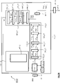
- the coding method is implemented in a coding device or coder CO1 shown in figure 2A .
- the code instructions of the computer program PG_C1 are for example loaded into a RAM memory, MR_C1, before being executed by the processing circuit CT_C1.
- the coding process represented on the Figure 1A applies to any current multi-view image IMV j fixed or forming part of a sequence of multi-view images IMV 1 , ..., IMV j ,..., IMV K (1 ⁇ j ⁇ K) to code.
- a current multi-view image IMV j at a current instant t j is composed of N different views V 1 , j , V 2,j,...., V u,j ,..., V N,j which each represent the same scene according to a corresponding angular viewing position, such that N>1 and 1 ⁇ u ⁇ N.
- a sequence of multi-view images comprises a plurality K of multi-view images IMV 1 , IMV 2 ,..., IMV j, ,..., IMV K , such that 1 ⁇ j ⁇ K, which respectively follow the instants t1, t2,...,tj,..., tK.
- the multi-view image IMV 1 is made up of N different views V 1,1 , V 2,1,...., V u,1 ,..., V N,1 which represent each a same scene according to a corresponding angular viewing position.
- the multi-view image IMV 2 is made up of N different views V 1.2 , V 2.2,...., V u,2 ,..., V N,2 which represent each a same scene according to a corresponding angular viewing position.
- the multi-view image IMV j is made up of N different views V 1,j , V 2,j,...., Vu ,j ,..., V N,j which each represent the same scene according to a corresponding angular viewing position.
- the multi-view image IMV K is composed of N different views V 1 , K , V 2,K,...., V u,K ,..., V N,K which represent each a same scene according to a corresponding angular viewing position.
- step C1a) is implemented by a view coding device MCV_C1 as represented on the figure 2A , which device is controlled by the processor PROC_C1.
- the predictor view used to predict the at least one current view V u , j is a view which has already been coded and then decoded. Such a predictor view is stored beforehand in the buffer memory MT_C1 of the coder CO1 as shown in figure 2A .
- an optimal predictive view Vp u,j is obtained following competition between said predetermined prediction modes, for example by minimizing a well-known throughput distortion criterion of the skilled in the art.
- the optimal predictive view is considered as an approximation of the at least one current view V u,j considered.
- Such a sub-step C11a) is implemented by the prediction device PRED_C1 represented on the figure 2A .
- the coding step C1a) also comprises a sub-step C12a) during which the difference between the at least one current view V u,j and the optimal predictive view Vp u,j which has been selected at the end of sub-step C11a).
- a residual view Vr u,j is then obtained at the end of sub-step C12a).
- Such a sub-step C12a) is implemented by the calculation module CAL_C1 represented on the figure 2A .
- the coding step C1a) also comprises a sub-step C13a) during which the residual view Vr u,j is conventionally transformed according to a conventional direct transformation operation such as for example a DCT type transformation , DST or DWT, to produce a transformed view, designated by the reference Vt u,j .
- a conventional direct transformation operation such as for example a DCT type transformation , DST or DWT
- Such an operation is performed by the device MT_C1 represented on the figure 2A .
- the coding step C1a) also comprises a sub-step C14a) during which the transformed view Vt u,j is quantized conventionally according to a conventional quantization operation, such as for example a scalar or vector quantization .
- a conventional quantization operation such as for example a scalar or vector quantization .
- a set Vq u,j of quantized coefficients is then obtained at the end of this sub-step.
- Such a sub-step C14a) is performed by means of the quantization device MQ_C1 as shown in figure 2A .
- the coding step C1a) also comprises a sub-step C15a) during which the set Vq u,j of coefficients is conventionally encoded according to a predetermined order, such as in particular the “raster scan” order. .
- a set Vcq u,j of coded data is then obtained at the end of sub-step C15a).
- Such an entropy coding sub-step C15a) is implemented by the entropy coding module MCE_C1 represented on the figure 2A .
- Such a signal is then delivered via the SOR_C1 output of the CO1 encoder of the figure 2A , then transmitted by a communication network (not shown), to a remote terminal.
- This comprises a decoder which will be described in more detail in the remainder of the description.
- Step C2a) of producing such a signal is implemented by the data signal generation module MGF1, as shown in figure figure 2A .
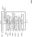
- the portion of the signal F'1 advantageously comprises a field CH 10 containing first information, designated for example by the symbol ⁇ , and representative of the fact that the first view VR 1 of the subsets of views of the sequence of images considered has been coded intra, the index pR 2 of at least the view VpR 2 which was used to predict the view VR 2 , the index pR W of at least the view VpR W which was used for the prediction of the view VR W , the index R W of at least the predictor view VR W which was used for the prediction of said at least one current view V u,j .
- step C2a it is then proceeded, during step C2a) represented on the Figure 1A , in the production of a portion of the data signal F'1, specifically associated with the coding of said at least one current view V u,j .
- such an elaboration further consists in adding to the signal F'1, in the field CH 10 , the index R W of at least the predictive view VR W which was used for the prediction of said at least a current view V u,j , in addition to the indices pR 2 , ..., pR W of predictive views already present in the field CH 10 .
- the addition of the index R W is not necessary in the case where it is already present in the field CH 10 .
- the field CH 10 has been supplemented by all the indices of the views predicting the views of the subset of views considered, prior to the coding of these views.
- the coding dependencies associated with said at least one current view V u,j are indicated in a grouped manner in the signal F'1 and will thus be made accessible quickly and directly during the decoding of said at least one least one current view V u,j .
- Such a step C3a) is implemented by a view decoding device MDV_C1 as represented on the figure 2A .
- Such an entropy decoding sub-step C31a) is implemented by the entropy decoding device MDE_C1 represented on the figure 2A .
- the coding step C3a) also comprises a sub-step C32a) during which the digital information obtained following the sub-step C31a) is dequantized according to a conventional dequantization operation which is the inverse operation of the quantization implemented in sub-step C14a). A set VDq u,j of dequantized coefficients is then obtained at the end of this sub-step.
- a sub-step C32a) is implemented by the dequantization device MQ -1 _C1 as shown in figure 2A .
- the coding step C3a) also comprises a sub-step C33a) during which a transformation is carried out of the set VDq u,j of quantized coefficients which is of the DCT -1 , DST -1 or DWT - type. 1 .
- This transformation is the inverse operation of the transformation performed in sub-step C13a).
- a decoded residual view is obtained, as designated by the reference VDr u,j .
- Such an operation is performed by the device MT -1 _C1 represented on the figure 2A .
- the coding step C3a) also comprises a sub-step C34a) of predicting said at least one current view V u,j to be decoded, by selection, in the buffer memory MT_C1 of the figure 2A , of the at least one optimal predictive view Vp u,j obtained following the aforementioned sub-step C11a), which is associated with the index decoded at the end of the sub-step C31a).
- Such a sub-step C34a) is implemented by the prediction device PRED -1 _C1 represented on the figure 2A .
- the coding step C3a) also comprises a calculation sub-step C35a), during which the at least one decoded view VD u,j is constructed (otherwise called inverse prediction) by adding to the at at least one decoded residual view VDr u,j obtained at the end of sub-step C33a), at least the predictive view Vp u,j which was identified at the aforementioned sub-step C31a).
- a calculation sub-step C35a during which the at least one decoded view VD u,j is constructed (otherwise called inverse prediction) by adding to the at at least one decoded residual view VDr u,j obtained at the end of sub-step C33a), at least the predictive view Vp u,j which was identified at the aforementioned sub-step C31a).
- Such a sub-step C35a) is implemented by the calculation device CAL -1 _C1 represented on the figure 2A .
- the current multi-view image IMV j is the fourth image IMV 4 of a sequence of multi-view images, each multi-view image comprising for example six views.
- the at least one coded current view which is considered in this example is for example the third view V 3.4 starting from the left, of the current multi-view image IMV 4 .
- View V 3.4 is shown in bold on the figure 5A .
- the current view V 3.4 is coded in Inter mode from the view V 3.3 of the multi-view image IMV3.
- View V 3.3 was itself coded in Inter with respect to view V 3.2 of multi-view image IMV2.
- the view V 3.2 was itself coded in Inter with respect to the view V 3.1 of the multi-view image IMV1.
- View V 3.1 was itself coded in Intra, this mode being represented by hatching on the figure 5A .
- the coding dependencies from one view to another are represented by arrows on the figure 5A .
- the current view V 3.4 is coded according to a coding tree structure comprising the view V 3.1 , the view V 3.2 and the view V 3.3 . Such a tree structure is represented in bold on the figure 5A .
- a first embodiment of the invention will now be described, in which the decoding method is used to decode at least one current view belonging to a multi-view image which has been previously coded in accordance with the method for coding the Figure 1A and whose coded data are contained in the data signal F1 or F'1.
- the at least one current view is capable of being decoded by a decoder conforming to any one of the current or future video decoding standards.
- the decoding method according to the first embodiment of the invention is for example implemented in software or hardware by modifications of such a decoder.
- the decoding method according to the invention is represented in the form of an algorithm comprising steps D1a) to D2a) as represented in Figure 6A .
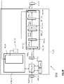
- the decoding method according to the invention is implemented in a decoding device or decoder DO1 shown in Figure 7A .
- the code instructions of the computer program PG_D1 are for example loaded into a RAM memory, MR_D1, before being executed by the processing circuit CT_D1.
- the decoding process represented on the Figure 6A applies to any current view V u,j of a current multi-view image IMV j fixed or forming part of a sequence of multi-view images IMV 1 , ..., IMV j ,..., IMV K (1 ⁇ j ⁇ K).
- the identification step D1a) is implemented by a signal analysis device MI_D1, as shown in Figure 7A .
- step D1a the process is carried out, during a step D2a) represented in Figure 6A , to the decoding of the at least one entropically coded current view V u,j .
- step D2a) is implemented by a view decoding device MDV_D1 as represented on the Figure 7A .
- a plurality of digital information items are obtained associated with the quantized data which have been coded during the entropy coding step C15a) of the Figure 1A .
- Such an entropy decoding sub-step D21a) is implemented by an entropy decoding device MDE_D1 of the view decoding device MDV_D1 of the Figure 7A .
- the index of the at least one predictor view Vp u,j which was used to predict the at least one current view V u,j during the substep C11a) of the Figure 1A is a view which has already been decoded or not. If the at least one predictor view Vp u,j has been decoded, it is stored beforehand in the buffer memory MT_D1 of the decoder DO1 of the Figure 7A . Otherwise, it is decoded from one or more views already decoded on the decoding path determined in a following step.
- the decoding step D2a) also comprises a sub-step D22a) during which the digital information obtained following the sub-step D21a) is dequantized according to a conventional dequantization operation which is the inverse operation of the quantization implemented during the quantization sub-step C14a) of the Figure 1A .
- a set VDq u,j of dequantized coefficients is then obtained at the end of sub-step D22a).
- Such a sub-step D22a) is implemented by a dequantization device MQ -1 _D1 of the view decoding device MDV_D1 of the Figure 7A .
- the decoding step D2a) also comprises a sub-step D23a) during which a transformation is carried out of the set VDq u,j of dequantized coefficients which is of the DCT -1 , DST -1 or DWT - type. 1 .
- This transformation is the inverse operation of the transformation performed in sub-step C13a) of the Figure 1A .
- Such an operation is performed by a Mr 1 _D1 reverse transformation device of the DCT -1 type (English abbreviation of "Discrete Cosine Transform"), DST -1 (English abbreviation of "Discrete Sine Transform”), DWT -1 (English abbreviation English version of “Discrete Wavelet Transform”).
- the transformation device MT -1 _D1 belongs to the view decoding device MDV_D1 of the Figure 7A .
- a sub-step D24a) of determination is carried out, in a set of views which belong to the current multi-view image IMV j or else to a another multi-view image of the sequence, of at least one view path necessary for decoding said at least one current view V u,j .
- Said at least one path comprises at least one view not yet decoded, designated by the reference Vnd i .
- Such an operation is performed by a calculation device CAL1_D1 belonging to the view decoding device MDV_D1 of the Figure 7A .
- the at least one not yet decoded view Vnd i located on the determined route is decoded.
- the construction (otherwise called inverse prediction) of the at least one decoded current view VD u,j is carried out by adding to the at least one decoded current residual view VDr u,j obtained at the end of the sub-step D23a), the at least one decoded view VDnd i which was obtained in the aforementioned sub-step D25a).
- Such a sub-step D26a) is implemented by a calculation device CAL2_D1 belonging to the view decoding device MDV_D1 of the Figure 7A .
- the at least one decoded current view VD u,j is then delivered by the output SOR_D1 of the decoder DO1, then is stored in the buffer memory MT_D1 so as to be used for the decoding of a next view to be decoded.
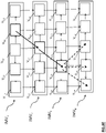
- FIG 8A is shown an example of decoding of at least one current view V u,j as coded with reference to the figure 5A .
- View V 6.1 is decoded with reference to view V 5.1 previously decoded.
- View V 5.2 is decoded with reference to view V 5.1 previously decoded.
- the current view V 4.3 is then decoded with reference to the decoded views V 4.2 and V 3.3 .
- the view V 4.3 is stored in the memory MT_D1 of the decoder of the Figure 7A , to be used for decoding future views.
- e) Let us now consider the fifth current view V 3.4 to be decoded. This view is decoded with reference to view V 3.3 which is itself decoded with reference to view V 3.2 which is itself decoded with reference to view V 3.1 . However, views V 3.1 and V 3.2 have already been decoded previously. The decoding method according to the invention therefore does not apply for the current view V 3.4 considered.
- the V 3.4 view is stored in the MT_D1 memory of the decoder of the Figure 7A , to be used for decoding future views.
- the decoding technique according to the invention is based on an innovative multi-view image coding method, as implemented by modifications of a coder conforming to any of the standards current or future video coding methods.
- the coding method in accordance with the second embodiment is represented in the form of an algorithm comprising steps C1b) to C3b) as represented in figure 1B .
- the coding method is implemented in a coding device or CO2 coder shown in figure 2B .
- the code instructions of the computer program PG_C2 are for example loaded into a RAM memory, MR_C2, before being executed by the processing circuit CT_C2.
- the coding process represented on the figure 1B applies to any current multi-view image IMV j fixed as represented in Figure 3A or forming part of a sequence of multi-view images IMV 1 , ..., IMV j ,..., IMV K (1 ⁇ j ⁇ K) to be coded, as shown in Figure 3B .
- step C1b) shown in figure 1B for a current multi-view image IMV j , said at least one view V u,j is coded.
- Such a step C1b) is implemented by a view coding device MCV_C2 as represented on the figure 2B .
- the at least two predictor views used to predict said at least one current view V u , j are views which have already been coded and then decoded.
- the at least two predictor views are stored beforehand in the buffer memory MT_C2 of the CO2 encoder as shown in figure 2B .
- At least two optimal predictive views Vp1 u,j and Vp2 u,j are obtained following competition between said predetermined prediction modes, for example by minimizing a bitrate distortion criterion well known to those skilled in the art.
- Each of the at least two optimal predictor views Vp1 u,j and Vp2 u,j is considered as the same approximation of said at least one current view V u,j considered.
- Such a sub-step C11b) is implemented by the prediction device PRED_C2 represented on the figure 2B .
- the coding step C1b) also comprises a sub-step C12b) during which the difference between said at least one view is calculated V u,j and, according to the invention, each of the at least two optimal predictive views Vp1 u,j and Vp2 u,j which have been selected at the end of sub-step C11b).
- At least two residual views Vr1 u,j and Vr2 u,j are then obtained at the end of sub-step C12b).
- Such a sub-step C12b) is implemented by the calculation device CAL_C2 represented on the figure 2B .
- the coding step C1b) also comprises a sub-step C13b) during which the at least two residual views Vr1 u,j and Vr2 u,j are transformed according to a conventional direct transformation operation such as by example a transformation of the DCT, DST or DWT type, to produce according to the invention at least two transformed views, designated respectively by the references Vt1 u,j and Vt2 u,j .
- a conventional direct transformation operation such as by example a transformation of the DCT, DST or DWT type
- the coding step C1b) also comprises a sub-step C14b) during which the at least two transformed views Vt1 u,j and Vt2 u,j are quantized according to a conventional quantization operation, such as by example a scalar or vector quantization. According to the invention, at least two sets Vq1 u,j and Vq2 u,j of quantized coefficients are then obtained at the end of this sub-step.
- a sub-step C14b) is implemented by means of the quantization device MQ_C2 as shown in figure 2B .
- the coding step C1b) also comprises a sub-step C15b) during which the at least two sets Vq1 u,j and Vq2 u,j of coefficients are conventionally coded, according to a predetermined order. According to the invention, at least two sets Vcq1 u,j and Vcq2 u,j of coded data are then obtained at the end of sub-step C15b).
- Such an entropy coding sub-step C15b) is implemented by the entropy coding device MCE_C2 represented on the figure 2B .
- Such a signal is then delivered via the SOR_C2 output of the CO2 encoder of the figure 2B , then transmitted by a communication network (not shown), to a remote terminal.
- This comprises a decoder which will be described in more detail in the remainder of the description.
- Step C2b) of producing such a signal is implemented by the data signal generation device MGF2, as shown in figure figure 2B .
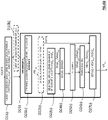
- the portion of the signal F'2 advantageously comprises a field CH' 101 containing first information, designated for example by the symbol ⁇ , and representative of the fact that the first view VR 1 of the subsets of views of the considered image sequence has been coded intra, the pR 2 index of at least the VpR view 2 which was used to predict the VR 2 view, the pR W1 index of at least the VpR view W1 which was used to predict the view VR W1 , the index pR W2 of at least the view VpR W2 which was used to predict the view VR W2 , the index R W1 of said first predictive view VR W1 which can be used to predict said at least one current view V u,j , the index R W2 of said at least second predictor view VR W2 which can be used to predict said at least one current view V u,j .
- first information designated for example by the symbol ⁇
- the indices R W1 and R W2 are grouped together in the field CH' 101 and separated by the symbol "/" to indicate that only one of them is selected according to the choice of the predictor view VR W1 or VR W2 which is implemented to predict said at least one current view V u,j .
- step C2b it is then proceeded, during step C2b) represented on the figure 1B , in the development of a portion of the data signal F'2 specifically associated with the coding of said at least one current view V u,j .
- such an elaboration further consists in adding to the signal F'2, in the field CH' 101 , in addition to the indices pR 2 , ..., pR W1 , pR W2 of predictive views already present in the field CH' 101 , the index R W1 of the first predictor view VR W1 which was used to predict said at least one current view V u,j and the index R W2 of the at least second predictor view VR W2 which was used to predict said at least one current view V u,j .
- the addition of the indices R W1 and R W2 is not necessary in the case where these indices are already present in the field CH′ 101 .
- the field CH′ 101 has been supplemented by all the indices of the views predicting the views of the subset of views considered, prior to the coding of these views.
- the coding dependencies associated with said at least one current view V u,j are indicated in a grouped manner in the signal F'2 and will thus be made accessible quickly and directly during the decoding of said at least one current view V u,j .
- Such a step C3b) is implemented by a view decoding device MDV_C2 as represented on the figure 2B .
- a plurality of associated digital information items according to the invention are obtained with at least two sets of quantized data Vcq1 u,j and Vcq2 u,j which have been coded during the aforementioned step C15b).
- Such an entropy decoding sub-step C31b) is implemented by the entropy decoding device MDE_C2 represented on the figure 2B .
- the index of the first predictor view Vp1 u,j and of the at least second predictor view Vp2 u,j which were used to predict said at least one current view is also decoded V u , j in sub-step C11b) of the figure 1B .
- the coding step C3b) also comprises a sub-step C32b) during which the digital information obtained following the sub-step C31b) is dequantized according to a conventional dequantization operation which is the inverse operation of the quantization implemented in sub-step C14b). At least two sets VDq1 u,j and VDq2 u,j of dequantized coefficients are then obtained at the end of this sub-step.
- a sub-step C32b) is implemented by the dequantization device MQ -1 _C2 as shown in figure 2B .
- the coding step C3b) also comprises a sub-step C33b) during which a transformation is carried out of each of the at least two sets VDq1 u,j and VDq2 u,j of dequantized coefficients, which is of the DCT type -1 , DST -1 or DWT -1 .
- This transformation is the inverse operation of the transformation performed in sub-step C13b).
- at least two decoded residual views are obtained, as designated respectively by the references VDr1 u,j and VDr2 u,j .
- Such an operation is performed by the device MT -1 _C2 represented on the figure 2B .
- the coding step C3b) also comprises a sub-step C34b) of predicting said at least one current view V u,j to be decoded, by selection, in the buffer memory MT_C2 of the figure 2B , of one or the other of the at least two optimal predictive views Vp1 u,j and Vp2 u,j which were obtained following the aforementioned sub-step C11b) and which are respectively associated with the two indices decoded at the end of sub-step C31b).
- Such a sub-step C34b) is implemented by the prediction device PRED -1 _C2 represented on the figure 2B .
- the coding step C3b) also comprises a calculation sub-step C35b), during which the construction (otherwise called inverse prediction) of said at least one decoded view VD u,j is carried out by adding to the one or the other of the at least two decoded residual views VDr1 u,j and VDr2 u,j obtained at the end of the sub-step C33b), respectively one or the other of the at least two predictive views Vp1 u ,j and Vp2 u,j which were identified in sub-step C31b) above.
- Such a sub-step C35b) is implemented by the calculation device CAL -1 _C2 represented on the figure 2B .
- the current multi-view image IMV j is the fourth image IMV 4 of a sequence of multi-view images, each multi-view image comprising for example six views.
- the at least one coded current view which is considered in this example is for example the third view V 3.4 of the current multi-view image IMV 4 .
- View V 3.4 is shown in bold on the figure 5B .
- the coding dependencies from one view to another are represented by arrows on the figure 5B .
- a second embodiment of the invention will now be described, in which the decoding method is used to decode at least one current view belonging to a multi-view image which has been previously coded in accordance with the method for coding the figure 1B and whose coded data are contained in the data signal F2 or F'2.
- Said at least one current view is capable of being decoded by a decoder conforming to any one of the current or future video decoding standards.
- the decoding method according to the second embodiment of the invention is for example implemented in software or hardware by modifications of such a decoder.
- the decoding method according to the invention is represented in the form of an algorithm comprising steps D1b) to D2b) as represented in figure 6B .
- the decoding method according to the invention is implemented in a decoding device or DO2 decoder shown in figure 7B .
- the code instructions of the computer program PG_D2 are for example loaded into a RAM memory, MR_D2, before being executed by the processing circuit CT_D2.
- the decoding process represented on the figure 6B applies to any current view V u,j of a current multi-view image IMV j fixed or forming part of a sequence of multi-view images IMV 1 , ..., IMV j ,..., IMV K (1 ⁇ j ⁇ K).
- the identification step D1b) is implemented by a signal analysis device MI_D2, as shown in figure 7B .
- step D1b the process is carried out, during a step D2b) represented in figure 6B , on decoding said at least one entropically coded view V u,j .
- step D2b) is implemented by a view decoding device MDV_D2 as represented on the figure 7B .
- a sub-step D21b) of determination is carried out, in a set of views which belong to the current multi-view image IMV j or else to a another multi-view image of the sequence, of at least one path PR' u,j of reference views necessary for decoding said at least one current view V u,j which, given the alternative coding trees implemented on coding, contains one of the first or at least second predictor views Vp1 u,j and Vp2 u,j .
- said at least one path PR′ u,j only contains one or more already decoded reference views.
- said at least one path PR′ u,j comprises at least one view not yet decoded, designated by the reference V′nd i .
- Such a route determination operation is performed by a calculation device CAL1_D2 belonging to the view decoding device MDV_D2 of the figure 7B .
- a substep is carried out D23b) for selecting one of the sets of entropically coded data Vcq1 u,j or Vcq2 u,j associated with said at least one view V u , j to be decoded.
- Such a sub-step D23b) is implemented by a selection device MS_D2 of the view decoding device MDV_D2 of the figure 7B .
- a plurality of digital information items associated with the set of entropically coded data Vcq1 u,j or Vcq2 u,j which has been selected is obtained.
- Such an entropy decoding sub-step D24b) is implemented by an entropy decoding device MDE_D2 of the view decoding device MDV_D2 of the figure 7B .
- the index of the predictive view Vp1 u,j or Vp2 u,j which was used to predict said at least one view is also decoded.
- the predictor view Vp1 u,j or Vp2 u,j is a view which has already been decoded or not. If the predictor view Vp1 u,j or Vp2 u,j has been decoded, it is stored beforehand in the buffer memory MT_D2 of the decoder DO2 of the figure 7B . Otherwise, it is decoded from one or more views already decoded on the determined route PR′ u,j .
- the decoding step D2b) also comprises a sub-step D25b) during which the digital information obtained following the sub-step D24b) is dequantized according to a conventional dequantization operation which is the inverse operation of the quantization implemented during the quantization sub-step C14b) of the figure 1B .
- a set VDq1 u,j or VDq2 u,j of dequantized coefficients is then obtained at the end of sub-step D25b).
- Such a sub-step D25b) is implemented by a dequantization device MQ -1 _D2 of the view decoding device MDV_D2 of the figure 7B .
- the decoding step D2b) also comprises a sub-step D26b) during which a transformation is carried out of the set VDq1 u,j or VDq2 u,j of dequantized coefficients, which is of the DCT -1 type, DST- 1 or DWT- 1 .
- This transformation is the inverse operation of the transformation performed in sub-step C13b) of the figure 1B .
- the at least one decoded current residual view is obtained, designated by the reference VDr1 u,j or VDr2 u,j .
- Such an operation is performed by an inverse transformation device MT -1 _D2 of DCT -1 , DST -1 , DWT -1 type.
- the transformation device MT -1 _D2 belongs to the view decoding device MDV_D2 of the figure 7B .
- the construction (otherwise called inverse prediction) of said at least one decoded view VD u,j is carried out by adding to the at least one decoded current residual view VDr1 u,j or VDr2 u,j obtained at the end of sub-step D26b), said at least one decoded view VD'nd i which was obtained in sub-step D22b) above.
- Such a sub-step D27b) is implemented by a calculation device CAL2_D2 belonging to the view decoding device MDV_D2 of the figure 7B .
- Said at least one decoded view VD u,j is then delivered by the output SOR_D2 of the decoder DO2, then is stored in the buffer memory MT_D2 so as to be used for the decoding of a next view to be decoded.
- the decoding method according to the second embodiment can be implemented independently of the decoding method according to the first embodiment of the Figure 6A or be implemented in combination with the latter.
- each current view considered is the one that a user chooses to request successively during his navigation from one view to another in the sequence of multi-view images IMV 1 to IMV 4 .
- these are views V 5,i , V 6.2 , V 5.3 , V 4.3 then V 3.4 .
- Such a navigation route is represented in bold on the figure 8B .
- the at least one current view to be decoded which is considered in this example is for example the first view V 5.1 that the user wishes to view.
- view V 5.1 can only be decoded from view V 4.1 which is not yet decoded.
- View V 4.1 is therefore first of all decoded intra (represented by hatching on the figure 8B ), then stored in the buffer memory MT_D2 of the figure 7B to be used for decoding future views.
- the view V 5.1 is then decoded in turn with reference to the view V 4.1 previously decoded, then stored in the buffer memory MT_D2 of the figure 7B to be used for decoding future views.
- the at least one current view to be decoded which is considered in this example is for example the second view V 6.2 that the user wishes to view.
- the view V 6.2 can be decoded from the view V 5.1 or from the view V 6.1 . Since the user has previously viewed view V 5.1 which has therefore been decoded for this purpose and which is therefore available in the buffer memory MT_D2 of the figure 7B , it is the view V 5.1 which is preferentially chosen to decode the view V 6.2 .
- the at least one current view to be decoded which is considered in this example is for example the third view V 5.3 that the user wishes to view.
- view V 5.3 can be decoded from view V 4.2 , view V 5.2 or view V 6.2 . Since the user has previously viewed view V 6.2 which has therefore been decoded for this purpose and which is therefore available in the buffer memory MT_D2 of the figure 7B , it is view V 6.2 which is preferentially chosen to decode view V 5.3 .
- the at least one current view to be decoded which is considered in this example is for example the fourth view V 4.3 that the user wishes to view.
- the view V 4.3 can be decoded from the view V 4.2 or from the view V 5.2 . Since the V 4.1 view was previously decoded and is therefore available in the MT_D2 buffer of the figure 7B , it is chosen to decode view V 4.2 with respect to view V 4.1 then to decode view V 4.3 with respect to view V 4.2 .
- the at least one current view to be decoded which is considered in this example is for example the fifth view V 3.4 that the user wishes to view.
- the view V 3.4 can be decoded from the view V 2.3 or from the view V 3.3 , the views V 2.3 and V 3.3 not having yet been decoded. It is chosen for example to decode the view V 2.3 .
- the view V 2.3 can be decoded from the view V 1.2 , V 2.2 or V 3.2 , the views V 1.2 , V 2.2 and V 3, 2 have not yet been decoded. It is chosen for example to decode the view V 1,2 .
- view V 1.2 can be decoded from view V 1.1 or V 2.1 , views V 1.1 , V 2.1 have not yet been decoded. It is chosen for example to decode the view V 1,1 .
- the decoding path of the current view V 3.4 determined from among several possible paths therefore includes, in the order of decoding to be implemented, the views not yet decoded V 1.1 , V 1.2 and V 2.3 .
- the view V 1.1 is decoded in Intra (represented by hatching on the figure 8B ).
- the view V 1,1 is stored in the memory MT_D2 of the decoder of the figure 7B , to be used for decoding future views.
- the view V 1.2 is then decoded with reference to the view V 1.1 previously decoded, then is stored in the memory MT_D2 of the decoder of the figure 7B , to be used for decoding future views.
- the view V 2.3 is then decoded with reference to the view V 1.2 previously decoded, then is stored in the memory MT_D2 of the decoder of the figure 7B , to be used for decoding future views.
- the view V 3.4 is decoded with reference to the view V 2.3 decoded previously, then is stored in the memory MT_D2 of the decoder of the figure 7B , to be used for decoding future views.
- the user has the possibility of navigating laterally from one view to another, at each time instant.
- a variant of the coding method of the figure 6B may allow less flexibility, while remaining realistic from a practical point of view.
- FIG. 8C An example of decoding of at least one current view V u,j according to this variant is represented on the Fig. 8C .
- said at least one current view is view V 2.4
- a single prediction residue symbolized by the arrow between view V 2.3 and view V 2.4
- three different prediction residues could for example be used alternately to reconstruct this view (symbolized respectively by the arrow between view V 1.3 and view V 2.4 , the arrow between view V 2.3 and view V 2.4 and the arrow between view V 3.3 and view V 2.4 ).
- each multi-view image comprises for example six views.
- each current view considered is the one that a user chooses to request successively during his navigation from one view to another in the sequence of multi-view images IMV 1 to IMV 4 .
- these are views V 5.1 , V 6.2 , V 5 .3 , then V 4.4 .
- Such a navigation route is represented in bold on the figure 8D .
- the views V 5.1 , V 6.2 , V 5.3 have been decoded in the same way as at the figure 8B and that the at least one current view to be decoded which is considered is for example the view V 4.4 that the user wishes to view.
- the decoding path of view V 4.4 which uses a minimum number of additional views to decode is that which consists in decoding the current view V 4.4 directly from view V 5.3 , which was viewed by the user at the previous instant t3 and has, therefore, already been decoded and therefore made available in the buffer memory MT_D2 of the figure 7B .
- the decoding path is greatly optimized since it does not contain any additional view to be decoded.
- Such an optimized decoding path is determined by taking into account the views already decoded on the navigation path from one view to another already carried out by the user, which is made possible given the proposed decoding tree which can be selected from several possible alternative trees.
- the second mode of determination which has just been described thus makes it possible to reduce the artefacts which tend to accumulate and to propagate during the decoding of one view with respect to the other in accordance with a non-intra prediction mode.
- the course of views necessary for decoding said at least one current view which was determined at the end of sub-step D24a) of the method for decoding the Figure 6A or at the end of sub-step D21b) of the method for decoding the figure 6B , does not make it possible to decode said at least one current view V u , j due to at least one decoding constraint, the at least one current view is replaced by another view of the multi-view image at the instant current tj, which is capable of being decoded, said other view being the closest spatially to the at least one current view.
- the decoder when determining the course of views necessary for decoding said at least one current view, the decoder is not able to decode the latter.
- Such a situation can for example occur when the decoder is subject to hardware constraints, such as in particular a maximum number NB max of views that can be decoded, and the view path necessary for decoding said at least one current view requires the decoding of a number of views greater than the number NB max .
- the at least one current view will then be replaced by the view which is closest to it spatially and which is decodable in accordance with the constraints of the decoder.
- the path of views necessary for decoding said at least one current view V u,j which is determined during the aforementioned determination sub-step D24a) or D21b) contains a view on which depends at least one view likely to be decoded at least one instant following or preceding the current instant tj.
- the current multi-view image IMV j is the third image IMV 3 of a sequence of multi-view images, each multi-view image comprising for example five views.
- the at least one current view to be decoded which is considered in this example is for example the third view V 2.3 of the current multi-view image IMV 3 .
- the image V 3.1 is decoded intra, this decoding mode being represented by hatching.
- An example of a navigation path from one view to another is represented in bold on the figure 8E . It contains, in order, views V 4.1 , V 3.2 , V 2.3 . Apart from these three views and view V 3.1 , all the other views represented have not yet been decoded.
- the course of views necessary for the decoding of the latter consists in taking into account either the view V 2.2 which has not yet been decoded, or the view V 3.3 which n also has not been decoded yet.
- the user could wish to view a view at a time preceding the current time t3, time t1 for example.
- the determination of the view path necessary for decoding said at least one current view is implemented by calculating the probability that such and such a view at at least one instant following or preceding the instant current is required to be decoded.
- a calculation can be determined according to the statistics related to the way the user navigates in the sequence of multi-view images.
- a probability model for the user's choice of views can be predefined or else be initialized equiprobably and continuously updated during decoding.
- the path selected will then be the one which "has the best chance" of being optimal afterwards, that is to say for example by the fact of containing a minimum number of additional views to be decoded in order to decode said at least one current view .
- Another way of predicting that such and such a view at least one instant following or preceding the current instant is required to be decoded consists in anticipating the fact that the user keeps the same direction of movement between two views viewed consecutively, these two views that can be located at the same time or at two different times.
- priority must be given to each of them.
- the route will be optimized as a priority by assessing the smallest distance between the at least one current view to be decoded and a view of the multi-view image sequence which was decoded intra.
- priority will be given to minimizing the number of views to be decoded.
- the second priority determination mode is then selected.
- Step D10a) is implemented by a management device MG_D1 represented on the Figure 7A .
- Step D10b) is implemented by a management device MG_D2 represented on the figure 7B .
- Such an arrangement advantageously saves the resources of the buffer memory MT_D1 or MT_D2 which are limited. It also makes it possible to have desynchronized buffer memories between the coder and the decoder, such desynchronization being made possible thanks to the implementation of the step of determining the path of views necessary for the decoding of said at least one current view and the decoding of the view(s) not yet decoded which have been identified on the determined route.
- the stored views furthest from the at least one current view will be the first to leave the buffer memory.
- the stored views furthest from the at least one current view will be the first to leave the buffer memory.
Landscapes
- Engineering & Computer Science (AREA)
- Multimedia (AREA)
- Signal Processing (AREA)
- Compression Or Coding Systems Of Tv Signals (AREA)
Claims (14)
- Verfahren zur Decodierung mindestens einer aktuellen Ansicht (Vu,j), die zu einem Bild mit Mehrfachansicht (IMVj) gehört, die zuvor codiert wurde und deren codierte Daten in einem Datensignal enthalten sind, wobei die mindestens eine aktuelle Ansicht eine gegebene Perspektive einer Szene darstellt, wobei das Datensignal einen Satz codierter Daten beinhaltet, die für mindestens einen Unterschied zwischen der mindestens einen aktuellen Ansicht und mindestens einer anderen Ansicht (Vpu,j; Vp1u,j, Vp2u,j) des Bildes mit Mehrfachansicht oder eines anderen Bildes mit Mehrfachansicht repräsentativ sind, wobei die mindestens eine andere Ansicht zur Vorhersage der mindestens einen aktuellen Ansicht gedient hat, wobei das Decodierungsverfahren Folgendes beinhaltet:- Bestimmung (D24a); D21b)), in dem Datensignal oder in einem anderen Datensignal, das für ein anderes Bild mit Mehrfachansicht repräsentativ ist, von codierten Daten, die mit mindestens einer Ansicht assoziiert sind, die zur Decodierung der mindestens einen aktuellen Ansicht erforderlich ist und die noch nicht decodiert wurde, wobei die mindestens eine Ansicht, die zur Decodierung der mindestens einen aktuellen Ansicht erforderlich ist, selber dazu bestimmt ist, decodiert zu werden, entweder unabhängig oder aber mit Bezug auf mindestens eine andere Ansicht, die bereits decodiert wurde oder nicht, wobei die mindestens eine Ansicht, die zur Decodierung der mindestens einen aktuellen Ansicht erforderlich ist, eine Ansicht darstellt, die sich in mindestens einem Verlauf (PRu,j; PR'u,j) von Ansichten befindet, die zur Decodierung der mindestens einen aktuellen Ansicht erforderlich sind, wobei der mindestens eine Verlauf einem Navigationsverlauf von einer Ansicht zur nächsten entspricht, der von einem Benutzer vorgenommen wird, um die aktuelle Ansicht zu erreichen,- Decodierung (D25a); D22b)) der mindestens einen, noch nicht decodierten Ansicht, die sich in dem mindestens einen Verlauf befindet,wobei das Decodierungsverfahren dadurch gekennzeichnet ist, dass es Folgendes beinhaltet:- Identifikation (D1b)), in dem Datensignal:- von ersten codierten Daten (Vcq1u,j), die für einen Unterschied zwischen der mindestens einen aktuellen Ansicht und einer ersten Ansicht des Bildes mit Mehrfachansicht oder eines anderen Bildes mit Mehrfachansicht repräsentativ sind,- von mindestens zweiten codierten Daten (Vcq2u,j), die für einen Unterschied zwischen der mindestens einen aktuellen Ansicht und einer zweiten Ansicht des Bildes mit Mehrfachansicht oder eines anderen Bildes mit Mehrfachansicht repräsentativ sind,- Auswahl (D23b)) entweder der ersten codierten Daten oder der mindestens zweiten codierten Daten, wobei die Auswahl in Abhängigkeit von dem vorgenommenen Navigationsverlauf umgesetzt wird,- Decodierung (D2b)) der mindestens einen aktuellen Ansicht ausgehend von der mindestens einen decodierten Ansicht in dem mindestens einen Verlauf und ausgehend von denen der ersten und mindestens zweiten codierten Daten, die ausgewählt wurden.
- Decodierungsverfahren nach Anspruch 1, beinhaltend eine Bestimmung des mindestens einen Verlaufs durch das Lesen, in dem Datensignal, von Informationen, die für den mindestens einen Verlauf repräsentativ sind.
- Decodierungsverfahren nach einem der Ansprüche 1 bis 2, wobei die Bestimmung des mindestens einen Verlaufs von Ansichten, die zur Decodierung der mindestens einen aktuellen Ansicht erforderlich sind, gemäß einem Kriterium zur Minimierung der Anzahl von Ansichten, die sich in dem mindestens einen Verlauf befinden, umgesetzt wird.
- Decodierungsverfahren nach einem der Ansprüche 1 bis 2, wobei die Bestimmung des mindestens einen Verlaufs von Ansichten, die zur Decodierung der mindestens einen aktuellen Ansicht erforderlich sind, gemäß einem Kriterium zur Minimierung des Abstands zwischen mindestens einer Ansicht, die ohne Bezug auf andere Ansichten decodiert wurde, und der mindestens einen aktuellen Ansicht umgesetzt wird.
- Decodierungsverfahren nach einem der Ansprüche 1 bis 4, wobei der mindestens eine bestimmte Verlauf eine Ansicht enthält, von der mindestens eine Ansicht abhängt, die zu mindestens einem Zeitpunkt, der dem aktuellen Zeitpunkt folgt oder ihm vorausgeht, decodiert werden kann.
- Decodierungsverfahren nach einem der Ansprüche 1 bis 4, wobei die Bestimmung des mindestens einen Verlaufs umgesetzt wird, indem mit Hilfe einer Wahrscheinlichkeitsberechnung mindestens eine Ansicht ermittelt wird, die zu mindestens einem Zeitpunkt, der dem aktuellen Zeitpunkt folgt oder ihm vorausgeht, decodiert werden kann.
- Decodierungsverfahren nach einem der Ansprüche 1 bis 6, wobei, wenn es der mindestens eine Verlauf von Ansichten, die zur Decodierung der mindestens einen aktuellen Ansicht erforderlich sind, aufgrund mindestens einer Decodierungsbeschränkung nicht gestattet, die mindestens eine aktuelle Ansicht zu decodieren, die mindestens eine aktuelle Ansicht durch eine andere Ansicht des Bildes mit Mehrfachansicht zu dem aktuellen Zeitpunkt ersetzt wird, die dazu fähig ist, decodiert zu werden, wobei die andere Ansicht der mindestens einen aktuellen Ansicht räumlich am nächsten ist.
- Decodierungsverfahren nach einem der Ansprüche 1 bis 7, wobei die decodierten und verfügbaren Ansichten in einem Speicher gespeichert werden, wobei der Speicher in Abhängigkeit von dem zeitlichen Abstand, der diese von der mindestens einen zu decodierenden aktuellen Ansicht trennt, aktualisiert wird, oder aber dann, wenn alle Ansichten eines Bildes mit Mehrfachansicht, das dem Bild mit Mehrfachansicht zu dem aktuellen Zeitpunkt vorausgeht, decodiert sind.
- Vorrichtung zur Decodierung mindestens einer aktuellen Ansicht (Vu,j), die zu einem Bild mit Mehrfachansicht (IMVj) gehört, die zuvor codiert wurde und deren codierte Daten in einem Datensignal enthalten sind, wobei die mindestens eine aktuelle Ansicht eine gegebene Perspektive einer Szene darstellt, wobei das Datensignal einen Satz codierter Daten beinhaltet, die für mindestens einen Unterschied zwischen der mindestens einen aktuellen Ansicht und mindestens einer anderen Ansicht des Bildes mit Mehrfachansicht oder eines anderen Bildes mit Mehrfachansicht repräsentativ sind, wobei die mindestens eine andere Ansicht zur Vorhersage der mindestens einen aktuellen Ansicht gedient hat,
wobei die Decodierungsvorrichtung eine Verarbeitungsschaltung (CT_D1; CT_D2) beinhaltet, die dazu angeordnet ist, Folgendes umzusetzen:- Bestimmung, in dem Datensignal oder in einem anderen Datensignal, das für ein anderes Bild mit Mehrfachansicht repräsentativ ist, von codierten Daten, die mit mindestens einer Ansicht assoziiert sind, die zur Decodierung der mindestens einen aktuellen Ansicht erforderlich ist und die noch nicht decodiert wurde, wobei die mindestens eine Ansicht, die zur Decodierung der mindestens einen aktuellen Ansicht erforderlich ist, selber dazu bestimmt ist, decodiert zu werden, entweder unabhängig oder aber mit Bezug auf mindestens eine andere Ansicht, die bereits decodiert wurde oder nicht, wobei die mindestens eine Ansicht, die zur Decodierung der mindestens einen aktuellen Ansicht erforderlich ist, eine Ansicht darstellt, die sich in mindestens einem Verlauf (PRu,j; PR'u,j) von Ansichten befindet, die zur Decodierung der mindestens einen aktuellen Ansicht erforderlich sind, wobei der mindestens eine Verlauf einem Navigationsverlauf von einer Ansicht zur nächsten entspricht, der von einem Benutzer vorgenommen wird, um die aktuelle Ansicht zu erreichen,- Decodierung der mindestens einen, noch nicht decodierten Ansicht, die sich in dem mindestens einen Verlauf befindet,wobei die Decodierungsvorrichtung dadurch gekennzeichnet ist, dass die Verarbeitungsschaltung dazu angeordnet ist, Folgendes umzusetzen:- Identifikation, in dem Datensignal:- von ersten codierten Daten (Vcq1u,j), die für einen Unterschied zwischen der mindestens einen aktuellen Ansicht und einer ersten Ansicht des Bildes mit Mehrfachansicht oder eines anderen Bildes mit Mehrfachansicht repräsentativ sind,- von mindestens zweiten codierten Daten (Vcq2u,j), die für einen Unterschied zwischen der mindestens einen aktuellen Ansicht und einer zweiten Ansicht des Bildes mit Mehrfachansicht oder eines anderen Bildes mit Mehrfachansicht repräsentativ sind,- Auswahl entweder der ersten codierten Daten oder der mindestens zweiten codierten Daten, wobei die Auswahl in Abhängigkeit von dem vorgenommenen Navigationsverlauf umgesetzt wird,- Decodierung der mindestens einen aktuellen Ansicht, die ausgehend von der mindestens einen decodierten Ansicht in dem mindestens einen Verlauf und ausgehend von denen der ersten und mindestens zweiten codierten Daten, die ausgewählt wurden, umgesetzt wird. - Computerprogramm, das Programmcodeanweisungen zur Ausführung der Schritte des Decodierungsverfahrens nach einem der Ansprüche 1 bis 8 beinhaltet, wenn es auf einem Computer ausgeführt wird.
- Computerlesbares Aufzeichnungsmedium, auf dem ein Computerprogramm aufgezeichnet ist, das Programmcodeanweisungen zur Ausführung der Schritte des Decodierungsverfahrens nach einem der Ansprüche 1 bis 8 beinhaltet, wenn es auf einem Computer ausgeführt wird.
- Verfahren zur Codierung mindestens eines Bildes mit Mehrfachansicht (IMVj), bei dem die Codierung mindestens einer aktuellen Ansicht (Vu,j) des Bildes mit Mehrfachansicht umgesetzt wird, wobei die mindestens eine aktuelle Ansicht eine gegebene Perspektive einer Szene darstellt, beinhaltend:- die Codierung eines Satzes Daten, die für mindestens einen Unterschied zwischen der mindestens einen aktuellen Ansicht und mindestens einer anderen Ansicht (Vpu,j; Vplu,j, Vp2u,j) des Bildes mit Mehrfachansicht oder eines anderen Bildes mit Mehrfachansicht repräsentativ sind, wobei die mindestens eine andere Ansicht zur Vorhersage der mindestens einen aktuellen Ansicht gedient hat,- die Codierung von codierten Daten, die mit mindestens einer Ansicht assoziiert sind, die zur Codierung der mindestens einen aktuellen Ansicht erforderlich ist und die nicht decodiert ist, wobei die mindestens eine Ansicht, die zur Codierung der mindestens einen aktuellen Ansicht erforderlich ist, selber dazu bestimmt ist, codiert zu werden, entweder unabhängig oder aber mit Bezug auf mindestens eine andere Ansicht, die bereits decodiert wurde oder nicht, wobei die mindestens eine Ansicht, die zur Codierung der mindestens einen aktuellen Ansicht erforderlich ist, eine Ansicht darstellt, die sich in mindestens einem Verlauf (PRu,j; PR'u,j) von Ansichten befindet, die zur Codierung der mindestens einen aktuellen Ansicht erforderlich sind, wobei der mindestens eine Verlauf einem Navigationsverlauf von einer Ansicht zur nächsten bis zur aktuellen Ansicht entspricht, der von einem Benutzer bei der Decodierung vorgenommen werden kann,wobei das Codierungsverfahren dadurch gekennzeichnet ist, dass es Folgendes umsetzt:- eine erste Vorhersage (C12b)) der mindestens einen aktuellen Ansicht mit Bezug auf eine erste Ansicht (Vp1u,j) des Bildes mit Mehrfachansicht oder eines anderen Bildes mit Mehrfachansicht, was einen ersten Satz vorhergesagter Daten ergibt,- mindestens eine zweite Vorhersage (C12b)) der mindestens einen aktuellen Ansicht mit Bezug auf eine zweite Ansicht (Vp2u,j) des Bildes mit Mehrfachansicht oder eines anderen Bildes mit Mehrfachansicht, was mindestens einen zweiten Satz vorhergesagter Daten ergibt,- eine Codierung (C15b)) des ersten und des mindestens zweiten Satzes vorhergesagter Daten,- eine Erstellung (C2b)) eines Datensignals, das den Satz codierter Daten sowie den ersten und mindestens zweiten Satz codierter Daten beinhaltet,wobei einer von dem ersten und mindestens zweiten Satz codierter Daten dazu fähig ist, in Abhängigkeit von dem vorgenommenen Navigationsverlauf zur Decodierung der mindestens einen aktuellen Ansicht verwendet zu werden.
- Vorrichtung zur Codierung mindestens eines Bildes mit Mehrfachansicht (IMVj), beinhaltend eine Verarbeitungsschaltung (CT_C2), die dazu angeordnet ist, die Codierung mindestens einer aktuellen Ansicht des Bildes mit Mehrfachansicht umzusetzen, wobei die mindestens eine aktuelle Ansicht eine gegebene Perspektive einer Szene darstellt, wobei die Verarbeitungsschaltung die Codierung eines Satz Daten umsetzt, die für mindestens einen Unterschied zwischen der mindestens einen aktuellen Ansicht und mindestens einer anderen Ansicht (Vpu,j; Vp1u,j, Vp2u,j) des Bildes mit Mehrfachansicht oder eines anderen Bildes mit Mehrfachansicht repräsentativ sind, wobei die mindestens eine andere Ansicht zur Vorhersage der mindestens einen aktuellen Ansicht gedient hat,- die Codierung von codierten Daten, die mit mindestens einer Ansicht assoziiert sind, die zur Codierung der mindestens einen aktuellen Ansicht erforderlich ist und die nicht decodiert ist, wobei die mindestens eine Ansicht, die zur Codierung der mindestens einen aktuellen Ansicht erforderlich ist, selber dazu bestimmt ist, codiert zu werden, entweder unabhängig oder aber mit Bezug auf mindestens eine andere Ansicht, die bereits decodiert wurde oder nicht, wobei die mindestens eine Ansicht, die zur Codierung der mindestens einen aktuellen Ansicht erforderlich ist, eine Ansicht darstellt, die sich in mindestens einem Verlauf (PRu,j; PR'u,j) von Ansichten befindet, die zur Codierung der mindestens einen aktuellen Ansicht erforderlich sind, wobei der mindestens eine Verlauf einem Navigationsverlauf von einer Ansicht zur nächsten bis zur aktuellen Ansicht entspricht, der von einem Benutzer bei der Decodierung genommen werden kann,wobei die Codierungsvorrichtung dadurch gekennzeichnet ist, dass die Verarbeitungsschaltung ferner dazu angeordnet ist, Folgendes umzusetzen:- eine erste Vorhersage der mindestens einen aktuellen Ansicht mit Bezug auf eine erste Ansicht des Bildes mit Mehrfachansicht oder eines anderen Bildes mit Mehrfachansicht, was einen ersten Satz vorhergesagter Daten ergibt,- mindestens eine zweite Vorhersage der mindestens einen aktuellen Ansicht mit Bezug auf eine zweite Ansicht des Bildes mit Mehrfachansicht oder eines anderen Bildes mit Mehrfachansicht, was mindestens einen zweiten Satz vorhergesagter Daten ergibt,- eine Codierung des ersten und des mindestens zweiten Satzes vorhergesagter Daten,- eine Erstellung eines Datensignals, das den Satz codierter Daten sowie den ersten und mindestens zweiten Satz codierter Daten beinhaltet,wobei einer von dem ersten und mindestens zweiten Satz codierter Daten dazu fähig ist, in Abhängigkeit von dem genommenen Navigationsverlauf zur Decodierung der mindestens einen aktuellen Ansicht verwendet zu werden.
- Computerprogramm, das Programmcodeanweisungen zur Ausführung der Schritte des Codierungsverfahrens nach Anspruch 12 beinhaltet, wenn es auf einem Computer ausgeführt wird.
Applications Claiming Priority (2)
| Application Number | Priority Date | Filing Date | Title |
|---|---|---|---|
| FR1559592A FR3042368A1 (fr) | 2015-10-08 | 2015-10-08 | Procede de codage et de decodage multi-vues, dispositif de codage et de decodage multi-vues et programmes d'ordinateur correspondants |
| PCT/FR2016/052475 WO2017060587A1 (fr) | 2015-10-08 | 2016-09-29 | Codage et décodage multi-vues |
Publications (2)
| Publication Number | Publication Date |
|---|---|
| EP3360328A1 EP3360328A1 (de) | 2018-08-15 |
| EP3360328B1 true EP3360328B1 (de) | 2022-06-08 |
Family
ID=55236523
Family Applications (1)
| Application Number | Title | Priority Date | Filing Date |
|---|---|---|---|
| EP16785246.6A Active EP3360328B1 (de) | 2015-10-08 | 2016-09-29 | Mehrfachansichtscodierung und -decodierung |
Country Status (6)
| Country | Link |
|---|---|
| US (1) | US10893295B2 (de) |
| EP (1) | EP3360328B1 (de) |
| CN (1) | CN108293134B (de) |
| ES (1) | ES2926702T3 (de) |
| FR (1) | FR3042368A1 (de) |
| WO (1) | WO2017060587A1 (de) |
Families Citing this family (2)
| Publication number | Priority date | Publication date | Assignee | Title |
|---|---|---|---|---|
| JP7168848B2 (ja) * | 2018-11-21 | 2022-11-10 | 日本電信電話株式会社 | 評価装置、評価方法、及びプログラム。 |
| CN117396914A (zh) * | 2021-05-26 | 2024-01-12 | Oppo广东移动通信有限公司 | 使用特征全景图的全景视图重建 |
Family Cites Families (7)
| Publication number | Priority date | Publication date | Assignee | Title |
|---|---|---|---|---|
| US7903737B2 (en) * | 2005-11-30 | 2011-03-08 | Mitsubishi Electric Research Laboratories, Inc. | Method and system for randomly accessing multiview videos with known prediction dependency |
| WO2008084443A1 (en) * | 2007-01-09 | 2008-07-17 | Nokia Corporation | System and method for implementing improved decoded picture buffer management for scalable video coding and multiview video coding |
| KR101301181B1 (ko) * | 2007-04-11 | 2013-08-29 | 삼성전자주식회사 | 다시점 영상의 부호화, 복호화 방법 및 장치 |
| JP4837772B2 (ja) * | 2009-12-15 | 2011-12-14 | パナソニック株式会社 | 多視点動画像復号装置、多視点動画像復号方法、プログラム及び集積回路 |
| WO2013072484A1 (en) * | 2011-11-18 | 2013-05-23 | Fraunhofer-Gesellschaft zur Förderung der angewandten Forschung e.V. | Multi-view coding with efficient residual handling |
| WO2014166096A1 (en) * | 2013-04-11 | 2014-10-16 | Mediatek Singapore Pte. Ltd. | Reference view derivation for inter-view motion prediction and inter-view residual prediction |
| CN104768015B (zh) * | 2014-01-02 | 2018-10-26 | 寰发股份有限公司 | 视频编码方法及装置 |
-
2015
- 2015-10-08 FR FR1559592A patent/FR3042368A1/fr not_active Withdrawn
-
2016
- 2016-09-29 WO PCT/FR2016/052475 patent/WO2017060587A1/fr not_active Ceased
- 2016-09-29 CN CN201680067867.6A patent/CN108293134B/zh active Active
- 2016-09-29 US US15/766,992 patent/US10893295B2/en active Active
- 2016-09-29 ES ES16785246T patent/ES2926702T3/es active Active
- 2016-09-29 EP EP16785246.6A patent/EP3360328B1/de active Active
Also Published As
| Publication number | Publication date |
|---|---|
| CN108293134A (zh) | 2018-07-17 |
| EP3360328A1 (de) | 2018-08-15 |
| ES2926702T3 (es) | 2022-10-27 |
| US10893295B2 (en) | 2021-01-12 |
| CN108293134B (zh) | 2022-07-05 |
| FR3042368A1 (fr) | 2017-04-14 |
| US20180302648A1 (en) | 2018-10-18 |
| WO2017060587A1 (fr) | 2017-04-13 |
Similar Documents
| Publication | Publication Date | Title |
|---|---|---|
| EP2991351B1 (de) | Verfahren zur dekodierung von bildern | |
| EP2777269B1 (de) | Verfahren zur codierung und decodierung von bildern, codierungs- und decodierungsvorrichtung sowie entsprechende computerprogramme | |
| EP3061246B1 (de) | Verfahren zur codierung und decodierung von bildern, vorrichtung zur codierung und decodierung von bildern und entsprechende computerprogramme | |
| FR2894421A1 (fr) | Procede et dispositif de decodage d'un flux video code suivant un codage hierarchique | |
| EP2443835B1 (de) | Bewegungsvektorkodierung durch wettbewerb zwischen verschiedenen prediktoren | |
| EP2449783A1 (de) | Vorhersage eines bewegungsvektors einer aktuellen bildpartition in zeigeposition auf eine mehrere referenzbildpartitionen abdeckende referenzzone sowie codierung und decodierung mit einer derartigen vorhersage | |
| EP3649778B1 (de) | Verfahren zur kodierung und dekodierung von bildern, kodierungs- und dekodierungsvorrichtung, und korrespondierende computerprogramme | |
| EP3360328B1 (de) | Mehrfachansichtscodierung und -decodierung | |
| EP2716045B1 (de) | Verfahren, vorrichtung und computerprogramme zur enkodierung und dekodierung von bildern | |
| EP3198876B1 (de) | Erzeugung und codierung von integralen restbildern | |
| EP2761871B1 (de) | Dekoder-seitige bewegungschätzung durch mustervergleich | |
| FR3040578A1 (fr) | Procede de codage et de decodage d'images, dispositif de codage et de decodage d'images et programmes d'ordinateur correspondants | |
| EP3542533B1 (de) | Verfahren und vorrichtung zur codierung und decodierung von mehrfachansichtssequenzen | |
| EP3409016A1 (de) | Verfahren zur codierung und decodierung von daten, vorrichtung zur codierung und decodierung von daten und entsprechende computerprogramme | |
| EP3529987A1 (de) | Methode für die kodierung und dekodierung von bildparametern, vorrichtung für die kodierung und dekodierung von bildparametern und zugehörige computerprogramme | |
| EP3158749B1 (de) | Verfahren zur codierung und decodierung von bildern, vorrichtung zur codierung und decodierung von bildern und entsprechende computerprogramme | |
| EP3050298B1 (de) | Videocodierung und -decodierung durch vererbung eines feldes von bewegungsvektoren | |
| EP3259909B1 (de) | Bildcodierungs- und decodierungsverfahren, codierungs- und decodierungsvorrichtung sowie entsprechende computerprogramme | |
| EP2962459B1 (de) | Dispartitätsbewegungsvektorherleitung und 3d videokodierung und -dekodierung, die eine solche herleitung benutzen | |
| FR2832582A1 (fr) | Procede et dispositif de determination d'au moins un parametre de codage de donnees multimedia | |
| FR2927494A1 (fr) | Procede de decodage et codage d'une sequence d'images avec compensation de mouvement |
Legal Events
| Date | Code | Title | Description |
|---|---|---|---|
| STAA | Information on the status of an ep patent application or granted ep patent |
Free format text: STATUS: UNKNOWN |
|
| STAA | Information on the status of an ep patent application or granted ep patent |
Free format text: STATUS: THE INTERNATIONAL PUBLICATION HAS BEEN MADE |
|
| PUAI | Public reference made under article 153(3) epc to a published international application that has entered the european phase |
Free format text: ORIGINAL CODE: 0009012 |
|
| STAA | Information on the status of an ep patent application or granted ep patent |
Free format text: STATUS: REQUEST FOR EXAMINATION WAS MADE |
|
| 17P | Request for examination filed |
Effective date: 20180409 |
|
| AK | Designated contracting states |
Kind code of ref document: A1 Designated state(s): AL AT BE BG CH CY CZ DE DK EE ES FI FR GB GR HR HU IE IS IT LI LT LU LV MC MK MT NL NO PL PT RO RS SE SI SK SM TR |
|
| AX | Request for extension of the european patent |
Extension state: BA ME |
|
| DAV | Request for validation of the european patent (deleted) | ||
| DAX | Request for extension of the european patent (deleted) | ||
| STAA | Information on the status of an ep patent application or granted ep patent |
Free format text: STATUS: EXAMINATION IS IN PROGRESS |
|
| 17Q | First examination report despatched |
Effective date: 20190508 |
|
| RAP1 | Party data changed (applicant data changed or rights of an application transferred) |
Owner name: ORANGE |
|
| GRAP | Despatch of communication of intention to grant a patent |
Free format text: ORIGINAL CODE: EPIDOSNIGR1 |
|
| STAA | Information on the status of an ep patent application or granted ep patent |
Free format text: STATUS: GRANT OF PATENT IS INTENDED |
|
| INTG | Intention to grant announced |
Effective date: 20201117 |
|
| GRAJ | Information related to disapproval of communication of intention to grant by the applicant or resumption of examination proceedings by the epo deleted |
Free format text: ORIGINAL CODE: EPIDOSDIGR1 |
|
| STAA | Information on the status of an ep patent application or granted ep patent |
Free format text: STATUS: EXAMINATION IS IN PROGRESS |
|
| GRAS | Grant fee paid |
Free format text: ORIGINAL CODE: EPIDOSNIGR3 |
|
| STAA | Information on the status of an ep patent application or granted ep patent |
Free format text: STATUS: GRANT OF PATENT IS INTENDED |
|
| INTC | Intention to grant announced (deleted) | ||
| GRAP | Despatch of communication of intention to grant a patent |
Free format text: ORIGINAL CODE: EPIDOSNIGR1 |
|
| INTG | Intention to grant announced |
Effective date: 20210407 |
|
| GRAJ | Information related to disapproval of communication of intention to grant by the applicant or resumption of examination proceedings by the epo deleted |
Free format text: ORIGINAL CODE: EPIDOSDIGR1 |
|
| GRAL | Information related to payment of fee for publishing/printing deleted |
Free format text: ORIGINAL CODE: EPIDOSDIGR3 |
|
| STAA | Information on the status of an ep patent application or granted ep patent |
Free format text: STATUS: EXAMINATION IS IN PROGRESS |
|
| RAP3 | Party data changed (applicant data changed or rights of an application transferred) |
Owner name: ORANGE |
|
| GRAP | Despatch of communication of intention to grant a patent |
Free format text: ORIGINAL CODE: EPIDOSNIGR1 |
|
| STAA | Information on the status of an ep patent application or granted ep patent |
Free format text: STATUS: GRANT OF PATENT IS INTENDED |
|
| INTC | Intention to grant announced (deleted) | ||
| INTG | Intention to grant announced |
Effective date: 20210818 |
|
| GRAJ | Information related to disapproval of communication of intention to grant by the applicant or resumption of examination proceedings by the epo deleted |
Free format text: ORIGINAL CODE: EPIDOSDIGR1 |
|
| GRAL | Information related to payment of fee for publishing/printing deleted |
Free format text: ORIGINAL CODE: EPIDOSDIGR3 |
|
| STAA | Information on the status of an ep patent application or granted ep patent |
Free format text: STATUS: EXAMINATION IS IN PROGRESS |
|
| INTC | Intention to grant announced (deleted) | ||
| GRAP | Despatch of communication of intention to grant a patent |
Free format text: ORIGINAL CODE: EPIDOSNIGR1 |
|
| STAA | Information on the status of an ep patent application or granted ep patent |
Free format text: STATUS: GRANT OF PATENT IS INTENDED |
|
| INTG | Intention to grant announced |
Effective date: 20220120 |
|
| GRAA | (expected) grant |
Free format text: ORIGINAL CODE: 0009210 |
|
| STAA | Information on the status of an ep patent application or granted ep patent |
Free format text: STATUS: THE PATENT HAS BEEN GRANTED |
|
| AK | Designated contracting states |
Kind code of ref document: B1 Designated state(s): AL AT BE BG CH CY CZ DE DK EE ES FI FR GB GR HR HU IE IS IT LI LT LU LV MC MK MT NL NO PL PT RO RS SE SI SK SM TR |
|
| REG | Reference to a national code |
Ref country code: GB Ref legal event code: FG4D Free format text: NOT ENGLISH |
|
| REG | Reference to a national code |
Ref country code: AT Ref legal event code: REF Ref document number: 1497734 Country of ref document: AT Kind code of ref document: T Effective date: 20220615 Ref country code: CH Ref legal event code: EP |
|
| REG | Reference to a national code |
Ref country code: DE Ref legal event code: R096 Ref document number: 602016072713 Country of ref document: DE |
|
| REG | Reference to a national code |
Ref country code: IE Ref legal event code: FG4D Free format text: LANGUAGE OF EP DOCUMENT: FRENCH |
|
| REG | Reference to a national code |
Ref country code: LT Ref legal event code: MG9D |
|
| REG | Reference to a national code |
Ref country code: NL Ref legal event code: MP Effective date: 20220608 |
|
| REG | Reference to a national code |
Ref country code: ES Ref legal event code: FG2A Ref document number: 2926702 Country of ref document: ES Kind code of ref document: T3 Effective date: 20221027 |
|
| PG25 | Lapsed in a contracting state [announced via postgrant information from national office to epo] |
Ref country code: SE Free format text: LAPSE BECAUSE OF FAILURE TO SUBMIT A TRANSLATION OF THE DESCRIPTION OR TO PAY THE FEE WITHIN THE PRESCRIBED TIME-LIMIT Effective date: 20220608 Ref country code: NO Free format text: LAPSE BECAUSE OF FAILURE TO SUBMIT A TRANSLATION OF THE DESCRIPTION OR TO PAY THE FEE WITHIN THE PRESCRIBED TIME-LIMIT Effective date: 20220908 Ref country code: LT Free format text: LAPSE BECAUSE OF FAILURE TO SUBMIT A TRANSLATION OF THE DESCRIPTION OR TO PAY THE FEE WITHIN THE PRESCRIBED TIME-LIMIT Effective date: 20220608 Ref country code: HR Free format text: LAPSE BECAUSE OF FAILURE TO SUBMIT A TRANSLATION OF THE DESCRIPTION OR TO PAY THE FEE WITHIN THE PRESCRIBED TIME-LIMIT Effective date: 20220608 Ref country code: GR Free format text: LAPSE BECAUSE OF FAILURE TO SUBMIT A TRANSLATION OF THE DESCRIPTION OR TO PAY THE FEE WITHIN THE PRESCRIBED TIME-LIMIT Effective date: 20220909 Ref country code: FI Free format text: LAPSE BECAUSE OF FAILURE TO SUBMIT A TRANSLATION OF THE DESCRIPTION OR TO PAY THE FEE WITHIN THE PRESCRIBED TIME-LIMIT Effective date: 20220608 Ref country code: BG Free format text: LAPSE BECAUSE OF FAILURE TO SUBMIT A TRANSLATION OF THE DESCRIPTION OR TO PAY THE FEE WITHIN THE PRESCRIBED TIME-LIMIT Effective date: 20220908 |
|
| REG | Reference to a national code |
Ref country code: AT Ref legal event code: MK05 Ref document number: 1497734 Country of ref document: AT Kind code of ref document: T Effective date: 20220608 |
|
| PG25 | Lapsed in a contracting state [announced via postgrant information from national office to epo] |
Ref country code: RS Free format text: LAPSE BECAUSE OF FAILURE TO SUBMIT A TRANSLATION OF THE DESCRIPTION OR TO PAY THE FEE WITHIN THE PRESCRIBED TIME-LIMIT Effective date: 20220608 Ref country code: LV Free format text: LAPSE BECAUSE OF FAILURE TO SUBMIT A TRANSLATION OF THE DESCRIPTION OR TO PAY THE FEE WITHIN THE PRESCRIBED TIME-LIMIT Effective date: 20220608 |
|
| PG25 | Lapsed in a contracting state [announced via postgrant information from national office to epo] |
Ref country code: NL Free format text: LAPSE BECAUSE OF FAILURE TO SUBMIT A TRANSLATION OF THE DESCRIPTION OR TO PAY THE FEE WITHIN THE PRESCRIBED TIME-LIMIT Effective date: 20220608 |
|
| PG25 | Lapsed in a contracting state [announced via postgrant information from national office to epo] |
Ref country code: SM Free format text: LAPSE BECAUSE OF FAILURE TO SUBMIT A TRANSLATION OF THE DESCRIPTION OR TO PAY THE FEE WITHIN THE PRESCRIBED TIME-LIMIT Effective date: 20220608 Ref country code: SK Free format text: LAPSE BECAUSE OF FAILURE TO SUBMIT A TRANSLATION OF THE DESCRIPTION OR TO PAY THE FEE WITHIN THE PRESCRIBED TIME-LIMIT Effective date: 20220608 Ref country code: RO Free format text: LAPSE BECAUSE OF FAILURE TO SUBMIT A TRANSLATION OF THE DESCRIPTION OR TO PAY THE FEE WITHIN THE PRESCRIBED TIME-LIMIT Effective date: 20220608 Ref country code: PT Free format text: LAPSE BECAUSE OF FAILURE TO SUBMIT A TRANSLATION OF THE DESCRIPTION OR TO PAY THE FEE WITHIN THE PRESCRIBED TIME-LIMIT Effective date: 20221010 Ref country code: EE Free format text: LAPSE BECAUSE OF FAILURE TO SUBMIT A TRANSLATION OF THE DESCRIPTION OR TO PAY THE FEE WITHIN THE PRESCRIBED TIME-LIMIT Effective date: 20220608 Ref country code: CZ Free format text: LAPSE BECAUSE OF FAILURE TO SUBMIT A TRANSLATION OF THE DESCRIPTION OR TO PAY THE FEE WITHIN THE PRESCRIBED TIME-LIMIT Effective date: 20220608 Ref country code: AT Free format text: LAPSE BECAUSE OF FAILURE TO SUBMIT A TRANSLATION OF THE DESCRIPTION OR TO PAY THE FEE WITHIN THE PRESCRIBED TIME-LIMIT Effective date: 20220608 |
|
| PG25 | Lapsed in a contracting state [announced via postgrant information from national office to epo] |
Ref country code: PL Free format text: LAPSE BECAUSE OF FAILURE TO SUBMIT A TRANSLATION OF THE DESCRIPTION OR TO PAY THE FEE WITHIN THE PRESCRIBED TIME-LIMIT Effective date: 20220608 Ref country code: IS Free format text: LAPSE BECAUSE OF FAILURE TO SUBMIT A TRANSLATION OF THE DESCRIPTION OR TO PAY THE FEE WITHIN THE PRESCRIBED TIME-LIMIT Effective date: 20221008 |
|
| REG | Reference to a national code |
Ref country code: DE Ref legal event code: R097 Ref document number: 602016072713 Country of ref document: DE |
|
| PG25 | Lapsed in a contracting state [announced via postgrant information from national office to epo] |
Ref country code: AL Free format text: LAPSE BECAUSE OF FAILURE TO SUBMIT A TRANSLATION OF THE DESCRIPTION OR TO PAY THE FEE WITHIN THE PRESCRIBED TIME-LIMIT Effective date: 20220608 |
|
| PLBE | No opposition filed within time limit |
Free format text: ORIGINAL CODE: 0009261 |
|
| STAA | Information on the status of an ep patent application or granted ep patent |
Free format text: STATUS: NO OPPOSITION FILED WITHIN TIME LIMIT |
|
| PG25 | Lapsed in a contracting state [announced via postgrant information from national office to epo] |
Ref country code: MC Free format text: LAPSE BECAUSE OF FAILURE TO SUBMIT A TRANSLATION OF THE DESCRIPTION OR TO PAY THE FEE WITHIN THE PRESCRIBED TIME-LIMIT Effective date: 20220608 Ref country code: DK Free format text: LAPSE BECAUSE OF FAILURE TO SUBMIT A TRANSLATION OF THE DESCRIPTION OR TO PAY THE FEE WITHIN THE PRESCRIBED TIME-LIMIT Effective date: 20220608 |
|
| REG | Reference to a national code |
Ref country code: CH Ref legal event code: PL |
|
| 26N | No opposition filed |
Effective date: 20230310 |
|
| REG | Reference to a national code |
Ref country code: BE Ref legal event code: MM Effective date: 20220930 |
|
| PG25 | Lapsed in a contracting state [announced via postgrant information from national office to epo] |
Ref country code: SI Free format text: LAPSE BECAUSE OF FAILURE TO SUBMIT A TRANSLATION OF THE DESCRIPTION OR TO PAY THE FEE WITHIN THE PRESCRIBED TIME-LIMIT Effective date: 20220608 |
|
| PG25 | Lapsed in a contracting state [announced via postgrant information from national office to epo] |
Ref country code: LU Free format text: LAPSE BECAUSE OF NON-PAYMENT OF DUE FEES Effective date: 20220929 |
|
| PG25 | Lapsed in a contracting state [announced via postgrant information from national office to epo] |
Ref country code: LI Free format text: LAPSE BECAUSE OF NON-PAYMENT OF DUE FEES Effective date: 20220930 Ref country code: IE Free format text: LAPSE BECAUSE OF NON-PAYMENT OF DUE FEES Effective date: 20220929 Ref country code: CH Free format text: LAPSE BECAUSE OF NON-PAYMENT OF DUE FEES Effective date: 20220930 |
|
| PG25 | Lapsed in a contracting state [announced via postgrant information from national office to epo] |
Ref country code: BE Free format text: LAPSE BECAUSE OF NON-PAYMENT OF DUE FEES Effective date: 20220930 |
|
| PG25 | Lapsed in a contracting state [announced via postgrant information from national office to epo] |
Ref country code: HU Free format text: LAPSE BECAUSE OF FAILURE TO SUBMIT A TRANSLATION OF THE DESCRIPTION OR TO PAY THE FEE WITHIN THE PRESCRIBED TIME-LIMIT; INVALID AB INITIO Effective date: 20160929 |
|
| PG25 | Lapsed in a contracting state [announced via postgrant information from national office to epo] |
Ref country code: CY Free format text: LAPSE BECAUSE OF FAILURE TO SUBMIT A TRANSLATION OF THE DESCRIPTION OR TO PAY THE FEE WITHIN THE PRESCRIBED TIME-LIMIT Effective date: 20220608 |
|
| PG25 | Lapsed in a contracting state [announced via postgrant information from national office to epo] |
Ref country code: MK Free format text: LAPSE BECAUSE OF FAILURE TO SUBMIT A TRANSLATION OF THE DESCRIPTION OR TO PAY THE FEE WITHIN THE PRESCRIBED TIME-LIMIT Effective date: 20220608 |
|
| PG25 | Lapsed in a contracting state [announced via postgrant information from national office to epo] |
Ref country code: TR Free format text: LAPSE BECAUSE OF FAILURE TO SUBMIT A TRANSLATION OF THE DESCRIPTION OR TO PAY THE FEE WITHIN THE PRESCRIBED TIME-LIMIT Effective date: 20220608 |
|
| PG25 | Lapsed in a contracting state [announced via postgrant information from national office to epo] |
Ref country code: MT Free format text: LAPSE BECAUSE OF FAILURE TO SUBMIT A TRANSLATION OF THE DESCRIPTION OR TO PAY THE FEE WITHIN THE PRESCRIBED TIME-LIMIT Effective date: 20220608 |
|
| PG25 | Lapsed in a contracting state [announced via postgrant information from national office to epo] |
Ref country code: BG Free format text: LAPSE BECAUSE OF FAILURE TO SUBMIT A TRANSLATION OF THE DESCRIPTION OR TO PAY THE FEE WITHIN THE PRESCRIBED TIME-LIMIT Effective date: 20220608 |
|
| PG25 | Lapsed in a contracting state [announced via postgrant information from national office to epo] |
Ref country code: BG Free format text: LAPSE BECAUSE OF FAILURE TO SUBMIT A TRANSLATION OF THE DESCRIPTION OR TO PAY THE FEE WITHIN THE PRESCRIBED TIME-LIMIT Effective date: 20220608 |
|
| PGFP | Annual fee paid to national office [announced via postgrant information from national office to epo] |
Ref country code: DE Payment date: 20250820 Year of fee payment: 10 |
|
| PGFP | Annual fee paid to national office [announced via postgrant information from national office to epo] |
Ref country code: IT Payment date: 20250820 Year of fee payment: 10 |
|
| PGFP | Annual fee paid to national office [announced via postgrant information from national office to epo] |
Ref country code: GB Payment date: 20250822 Year of fee payment: 10 |
|
| PGFP | Annual fee paid to national office [announced via postgrant information from national office to epo] |
Ref country code: FR Payment date: 20250820 Year of fee payment: 10 |
|
| PGFP | Annual fee paid to national office [announced via postgrant information from national office to epo] |
Ref country code: ES Payment date: 20251001 Year of fee payment: 10 |