EP3360422B1 - Machine de fabrication et de distribution de produits liquides ou semi-liquides - Google Patents
Machine de fabrication et de distribution de produits liquides ou semi-liquides Download PDFInfo
- Publication number
- EP3360422B1 EP3360422B1 EP18155301.7A EP18155301A EP3360422B1 EP 3360422 B1 EP3360422 B1 EP 3360422B1 EP 18155301 A EP18155301 A EP 18155301A EP 3360422 B1 EP3360422 B1 EP 3360422B1
- Authority
- EP
- European Patent Office
- Prior art keywords
- machine
- configuration
- exchanger
- connecting unit
- selective connecting
- Prior art date
- Legal status (The legal status is an assumption and is not a legal conclusion. Google has not performed a legal analysis and makes no representation as to the accuracy of the status listed.)
- Active
Links
Images



Classifications
-
- A—HUMAN NECESSITIES
- A23—FOODS OR FOODSTUFFS; TREATMENT THEREOF, NOT COVERED BY OTHER CLASSES
- A23G—COCOA; COCOA PRODUCTS, e.g. CHOCOLATE; SUBSTITUTES FOR COCOA OR COCOA PRODUCTS; CONFECTIONERY; CHEWING GUM; ICE-CREAM; PREPARATION THEREOF
- A23G9/00—Frozen sweets, e.g. ice confectionery, ice-cream; Mixtures therefor
- A23G9/04—Production of frozen sweets, e.g. ice-cream
- A23G9/045—Production of frozen sweets, e.g. ice-cream of slush-ice, e.g. semi-frozen beverage
-
- A—HUMAN NECESSITIES
- A23—FOODS OR FOODSTUFFS; TREATMENT THEREOF, NOT COVERED BY OTHER CLASSES
- A23G—COCOA; COCOA PRODUCTS, e.g. CHOCOLATE; SUBSTITUTES FOR COCOA OR COCOA PRODUCTS; CONFECTIONERY; CHEWING GUM; ICE-CREAM; PREPARATION THEREOF
- A23G9/00—Frozen sweets, e.g. ice confectionery, ice-cream; Mixtures therefor
- A23G9/04—Production of frozen sweets, e.g. ice-cream
- A23G9/08—Batch production
- A23G9/12—Batch production using means for stirring the contents in a non-moving container
-
- A—HUMAN NECESSITIES
- A23—FOODS OR FOODSTUFFS; TREATMENT THEREOF, NOT COVERED BY OTHER CLASSES
- A23G—COCOA; COCOA PRODUCTS, e.g. CHOCOLATE; SUBSTITUTES FOR COCOA OR COCOA PRODUCTS; CONFECTIONERY; CHEWING GUM; ICE-CREAM; PREPARATION THEREOF
- A23G9/00—Frozen sweets, e.g. ice confectionery, ice-cream; Mixtures therefor
- A23G9/04—Production of frozen sweets, e.g. ice-cream
- A23G9/14—Continuous production
- A23G9/18—Continuous production the products being on the outer wall of a cooled body, e.g. drum or endless band
-
- A—HUMAN NECESSITIES
- A23—FOODS OR FOODSTUFFS; TREATMENT THEREOF, NOT COVERED BY OTHER CLASSES
- A23G—COCOA; COCOA PRODUCTS, e.g. CHOCOLATE; SUBSTITUTES FOR COCOA OR COCOA PRODUCTS; CONFECTIONERY; CHEWING GUM; ICE-CREAM; PREPARATION THEREOF
- A23G9/00—Frozen sweets, e.g. ice confectionery, ice-cream; Mixtures therefor
- A23G9/04—Production of frozen sweets, e.g. ice-cream
- A23G9/20—Production of frozen sweets, e.g. ice-cream the products being mixed with gas, e.g. soft-ice
-
- A—HUMAN NECESSITIES
- A23—FOODS OR FOODSTUFFS; TREATMENT THEREOF, NOT COVERED BY OTHER CLASSES
- A23G—COCOA; COCOA PRODUCTS, e.g. CHOCOLATE; SUBSTITUTES FOR COCOA OR COCOA PRODUCTS; CONFECTIONERY; CHEWING GUM; ICE-CREAM; PREPARATION THEREOF
- A23G9/00—Frozen sweets, e.g. ice confectionery, ice-cream; Mixtures therefor
- A23G9/04—Production of frozen sweets, e.g. ice-cream
- A23G9/22—Details, component parts or accessories of apparatus insofar as not peculiar to a single one of the preceding groups
- A23G9/222—Freezing drums
-
- A—HUMAN NECESSITIES
- A23—FOODS OR FOODSTUFFS; TREATMENT THEREOF, NOT COVERED BY OTHER CLASSES
- A23G—COCOA; COCOA PRODUCTS, e.g. CHOCOLATE; SUBSTITUTES FOR COCOA OR COCOA PRODUCTS; CONFECTIONERY; CHEWING GUM; ICE-CREAM; PREPARATION THEREOF
- A23G9/00—Frozen sweets, e.g. ice confectionery, ice-cream; Mixtures therefor
- A23G9/04—Production of frozen sweets, e.g. ice-cream
- A23G9/22—Details, component parts or accessories of apparatus insofar as not peculiar to a single one of the preceding groups
- A23G9/224—Agitators or scrapers
-
- A—HUMAN NECESSITIES
- A23—FOODS OR FOODSTUFFS; TREATMENT THEREOF, NOT COVERED BY OTHER CLASSES
- A23G—COCOA; COCOA PRODUCTS, e.g. CHOCOLATE; SUBSTITUTES FOR COCOA OR COCOA PRODUCTS; CONFECTIONERY; CHEWING GUM; ICE-CREAM; PREPARATION THEREOF
- A23G9/00—Frozen sweets, e.g. ice confectionery, ice-cream; Mixtures therefor
- A23G9/04—Production of frozen sweets, e.g. ice-cream
- A23G9/22—Details, component parts or accessories of apparatus insofar as not peculiar to a single one of the preceding groups
- A23G9/228—Arrangement and mounting of control or safety devices
-
- A—HUMAN NECESSITIES
- A23—FOODS OR FOODSTUFFS; TREATMENT THEREOF, NOT COVERED BY OTHER CLASSES
- A23G—COCOA; COCOA PRODUCTS, e.g. CHOCOLATE; SUBSTITUTES FOR COCOA OR COCOA PRODUCTS; CONFECTIONERY; CHEWING GUM; ICE-CREAM; PREPARATION THEREOF
- A23G9/00—Frozen sweets, e.g. ice confectionery, ice-cream; Mixtures therefor
- A23G9/04—Production of frozen sweets, e.g. ice-cream
- A23G9/22—Details, component parts or accessories of apparatus insofar as not peculiar to a single one of the preceding groups
- A23G9/28—Details, component parts or accessories of apparatus insofar as not peculiar to a single one of the preceding groups for portioning or dispensing
-
- A—HUMAN NECESSITIES
- A23—FOODS OR FOODSTUFFS; TREATMENT THEREOF, NOT COVERED BY OTHER CLASSES
- A23G—COCOA; COCOA PRODUCTS, e.g. CHOCOLATE; SUBSTITUTES FOR COCOA OR COCOA PRODUCTS; CONFECTIONERY; CHEWING GUM; ICE-CREAM; PREPARATION THEREOF
- A23G9/00—Frozen sweets, e.g. ice confectionery, ice-cream; Mixtures therefor
- A23G9/04—Production of frozen sweets, e.g. ice-cream
- A23G9/22—Details, component parts or accessories of apparatus insofar as not peculiar to a single one of the preceding groups
- A23G9/30—Cleaning; Keeping clean; Sterilisation
-
- B—PERFORMING OPERATIONS; TRANSPORTING
- B67—OPENING, CLOSING OR CLEANING BOTTLES, JARS OR SIMILAR CONTAINERS; LIQUID HANDLING
- B67D—DISPENSING, DELIVERING OR TRANSFERRING LIQUIDS, NOT OTHERWISE PROVIDED FOR
- B67D1/00—Apparatus or devices for dispensing beverages on draught
- B67D1/08—Details
- B67D1/0857—Cooling arrangements
- B67D1/0858—Cooling arrangements using compression systems
Definitions
- This innovation relates to a machine for making and dispensing a liquid or semi-liquid food product, in particular cold products such as slushes, sorbets, cold creams, soft ice cream, etc.
- a need keenly felt in the sector in question is that of particularly quickly bringing the product from the icy or semi-icy state to the liquid state, when it must be completely removed from the processing tank for cleaning / product substitution.
- the icy product In light of this, the icy product must be rendered liquid in order to be able to completely remove it from the tank in a fast, easy way.
- the aim of this innovation is therefore to meet the above-mentioned requirements by providing a machine for making and dispensing a liquid or semi-liquid food product (hereinafter also defined as a cold or ice beverage), in particular but not limited to products such as slushes, sorbets, cold creams, soft ice cream, etc.
- a liquid or semi-liquid food product hereinafter also defined as a cold or ice beverage
- products such as slushes, sorbets, cold creams, soft ice cream, etc.
- the aim of this innovation is to provide a machine for making a liquid or semi-liquid food product (cold or ice beverage), in particular but not limited to products such as slushes, sorbets, creams, soft ice cream, etc., that allows the icy product present in the tank to be quickly and easily extracted.
- a liquid or semi-liquid food product cold or ice beverage
- products such as slushes, sorbets, creams, soft ice cream, etc.
- Document EP1980156 discloses a method for pasteurising and restoring the refrigerant cycle in a freezing machine for making crushed-ice drinks and the like comprises a pasteurising step during which a predetermined maximum temperature is reached and a step of restoring the refrigerant cycle, during which a predetermined freezing temperature is reached; the step of restoring the refrigerant cycle comprises a sub-step of rapid cooling of the pasteurising temperature with a first thermal excursion with passage from the temperature to a temperature and a sub-step of slow cooling from the temperature to the freezing temperature with a second thermal excursion, in which the first thermal excursion is greater than the second thermal excursion.
- Document EP0059330 shows a method of pasteurizing alimentary products or mixtures and of sterilizing the elements contacting such products and mixtures in the machines for making ice--cream products and/or for pasteurizing alimentary liquid mixtures and provided with a gas-compression refrigerating unit comprising a condenser connected at one side to the delivery of a refrigerant fluid from said compressor, and at the other side to the inlet of an evaporator which is in heat-exchange relationship with a chamber for treating and/or containing said products or mixtures, an expansion valve being interposed therebetween.
- Document EP2856888 shows a machine for the thermal treatment of liquid and semi-liquid food products which comprises: at least two tanks for containing respective products to be subjected to the thermal treatment, at least one dispenser for dispensing the product contained in said tanks, at least one stirrer mounted inside each tank for mixing the product contained therein, thermal treatment means operatively acting on the products contained in the containers.
- the thermal treatment means comprise at least one circuit for circulation of an operating fluid and at least two first heat exchangers operating according to a thermodynamic cycle; each of the two first heat exchangers being associated with a respective tank; said thermal treatment means being configured in such a way as to implement at least one operating mode of removing heat from the respective tank by means of one first heat exchanger and simultaneously transferring heat to the respective tank by means of the other first heat exchanger.
- Document US2002/033021 shows a method of operating a frozen beverage machine is disclosed that utilizes a short "burst" heating of the beverage machine's freezing chamber.
- the method includes monitoring a beverage mixture within the freezing chamber of the frozen beverage machine, and heating the freezing chamber for a predetermined time period in response to the beverage mixture reaching a first predetermined state.
- the freezing chamber is then refrigerated until the beverage mixture reaches a second predetermined state.
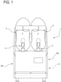
- the numeral 1 denotes a machine for making cold products (that is to say, products suitable for being made at a temperature below 0°C) such as slushes, sorbets, creams, soft ice cream, cold creams, etc.
- the machine 1 is adapted to make and dispense cold or ice beverages.
- the machine 1 for making and dispensing cold or ice beverages comprises at least:
- the machine 1 preferably comprises a containment compartment 13 at least for the second heat exchanger 7 and the compressor 11.
- the machine 1 further and preferably comprises, according to another aspect, at least one first airflow intake cavity 14A in fluid communication with said containment compartment 13 and with the outside environment and at least one second airflow release cavity 14B in fluid communication with said containment compartment 13 and with the outside environment.
- said second release cavity 14B is located above the first intake cavity 14A (that is to say, higher up), so as to create an airflow with a component moving from the bottom upwards.
- first intake cavity 14A and the second release cavity 14B are at two different heights means that it is possible to create an airflow that passes through the inner compartment 13.
- the airflow has a vertical (ascending) component and a horizontal component (directed from the front part of the machine 1 to the back part of it).
- stirrer 12 is a helical stirrer.
- the thermal treatment cylinder 8 comprises a longitudinal inner cavity (not illustrated), in which a motion transmission shaft passes freely.
- the motion transmission shaft (not illustrated) is coupled to the stirrer 12, preferably to the front portion of the stirrer 12.
- the machine 1 also comprises an electronic control and drive unit U.
- the machine 1 comprises a selection interface I, operatively acting on said electronic control and drive unit U for adjusting the operation of one or more elements of the machine 1.
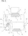
- the machine 1 comprises, downstream of said compressor 11 (with reference to the direction of normal circulation of the refrigerant fluid), a selective connecting unit 21.
- the selective connecting unit 21 is configured for alternately connecting the outfeed 11B of the compressor 11 to the infeed 6A of the first exchanger 6 or to the infeed 7A of the second exchanger 7.
- the selective connecting unit 21 is adapted to operate between a first configuration, in which it connects the outfeed 11B of the compressor to the infeed 6A of the first exchanger, and a second configuration in which it connects the outfeed 11B of the compressor to the infeed 7A of the second exchanger 7.
- control unit U is operatively connected to the selective connecting unit 21, for controlling it in such a way as to switch it to the two configurations, that is to say, the first configuration and the second configuration.
- the selective connecting unit 21 is a multi-way valve, with one infeed and two outfeeds.
- the selective connecting unit 21 is equipped with one infeed and two outfeeds.
- the valve or more generally the selective connecting unit 21, is configured to, selectively and alternately, put its own infeed 21A in fluid communication with one or the other of its own outfeeds (21B, 21C).
- the control unit U controls the selective connecting unit 21.
- the selective connecting unit 21 is normally in the first configuration when the machine 1 is in a production mode: in this mode the first exchanger 6 removes heat from the product in the tank 2, that is to say, a thermodynamic cooling cycle is carried out (preferably with vapour compression).
- the refrigerating plant 10 comprises a circuit in which a thermal carrier fluid is present, circulating in the compressor 11, first exchanger 6, second exchanger 7 and pressure reducing (i.e.: throttling) unit 16.
- the selective connecting unit 21 is normally in the second configuration when the machine 1 is in a defrost mode: in this mode the first exchanger 6 transfers heat to the surface of the cylinder 8 located in the tank 2.
- the plant 10 implements a "hot gas” technique, in which the first exchanger 6 transfers heat into the tank; in use, the refrigerant fluid, in the form of a gas is made to recirculate between the compressor and the first exchanger 6.
- the refrigerant fluid in the form of a gas heats up and transfers heat to the cylinder 8.
- the selection interface I comprises at least one control I1 for setting the configuration of the selective connecting unit 21 (between the first and the second operating modes), that is to say, for switching between the two configurations.
- the plant 10 comprises, at the outfeed 7B of the second exchanger 7, that is to say, downstream of the second exchanger 7, the pressure reducing unit 16.
- the outfeed 7B of the second exchanger 7 is connected to the infeed 16A of the pressure reducing unit 16.
- the infeed 7A of the second exchanger 7 is connected to an outfeed 21C of the connecting unit 21.
- Said pressure reducing unit 16 is preferably a throttle (expansion) valve.
- the outfeed 16B of the pressure reducing unit 16 is connected to the infeed 6A of the first exchanger 6.
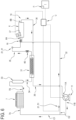
- Figure 6 shows a thermal treatment plant 10 for a tank 2, that is to say, adapted to cool the product in a tank 2.
- the thermal treatment plant 10 preferably comprises a first pipe 36 connecting the first exchanger 6 to the compressor 11, in particular a pipe 36 connecting the outfeed 6B of the first exchanger 6 to the infeed 11A of the compressor 11.
- the selective connecting unit 21 comprises at least one first valve 41, associated with the first circuit for closing it / opening it and at least one second valve 51, associated with the second circuit for closing it / opening it.
- first and second circuits share several components and pipes, whilst from the outfeed 11B of the compressor to the infeed 6A of the first exchanger said first and second circuits have two pipes C1,C2 (branches of the circuit) that are separate and parallel.
- the selective connecting unit 21 is operatively active on each of said two pipes C1,C2 (branches of the circuit) that are separate and parallel.
- first valve 41 is active on the pipe C1 whilst the second valve is active on the pipe C2.
- the first valve 41 and the second valve 51 are switched simultaneously.
- control unit is configured for controlling the first valve 41 and the second valve 51 in such a way as to switch them simultaneously. More precisely, when the first valve 41 is open and the second valve 51 is closed, and vice versa.
- the second valve 51 is located downstream of said compressor 11 (with reference to the direction of normal circulation of the refrigerant fluid), for closing a pipe 32 (which is part of the plant 10).
- the pipe 32 connects the outfeed 11B of the compressor with the infeed 6A of the first exchanger 6.
- Said valve 51 allows the pipe 32 to be opened or closed, that is to say, it may be switched between a closed configuration of the pipe 32 and an open configuration of the pipe 32.
- the thermal carrier fluid passes through the second exchanger 7, the auxiliary exchanger 31, the pressure reducing unit 16, the first exchanger 6 and the compressor 11, that is to say, it circulates along the entire first circuit.
- the first valve 41 and the second valve 51 are located on parallel branches C1, C2 which connect, respectively, the outfeed 11B of the compressor 11 with the infeed 6A of the first exchanger 6.
- the thermal plant 10 allows a vapour-compression thermodynamic cycle to be carried out (the fluid flows in the first circuit, performing a vapour-compression thermodynamic cycle between the various components).
- the first heat exchanger 6 absorbs heat from the liquid or semi-liquid product in the tank 2, cooling the liquid or semi-liquid product.
- the thermal carrier fluid flows through the first exchanger 6, the compressor 11, the pipe 32 and the further exchanger 31, that is to say, along the second circuit.
- the thermal plant 10 carries out a hot gas thermodynamic cycle.
- the first heat exchanger 6 transfers heat to the liquid or semi-liquid product in the tank 2, defrosting the liquid or semi-liquid product.
- control unit U controls the selective connecting device 21.
- the selective connecting device 21 is normally in the first configuration when the machine 1 is in a production mode: in this mode the first exchanger 6 removes heat from the product in the tank 2, that is to say, a thermodynamic cooling cycle is carried out (preferably a vapour-compression thermodynamic cycle).
- the selective connecting unit 21 is normally in the second heating configuration when the machine 1 is in a defrost mode: in this mode the first exchanger 6 transfers heat to the surface of the cylinder 8 located in the tank 2.
- the plant 10 implements a "hot gas” technique, in which the first exchanger 6 transfers heat into the tank; in use, the refrigerant fluid, in the form of a gas is made to recirculate between the compressor 11 and the first exchanger 6.
- the refrigerant fluid in the form of a gas heats up and transfers heat to the cylinder 8 due to circulation in the second circuit and in particular due to heating in the compressor 11.
- switching between the first and second configurations of the selective connecting unit 21 may occur at any time, when production, maintenance or cleaning require the switch to one or the other configuration (first or second).
- the selection interface I comprises at least one control I1 for setting the configuration of the selective connecting unit 21 (between the first and the second configuration), that is to say, for switching between the two configurations.
- the plant 10 comprises, at the outfeed 7B of the second exchanger 7, that is to say, downstream of the second exchanger 7, the pressure reducing unit 16.
- the second exchanger 7 is connected to the further exchanger 31 by means of a pipe 33.
- the further exchanger 31 is connected to the first exchanger 6 by means of a pipe 35.
- Said throttling unit 16 is preferably a throttle valve.
- the outfeed 16B of the throttling unit 16 is connected to the infeed 6A of the first exchanger 6.
- outfeed 6B of the first exchanger is connected to the infeed 11A of the compressor by means of a pipe 36 (that pipe 36 is shared by the first and second circuit).
- said pipe 36 affects the further exchanger 31.
- the plant 10 comprises an additional pressure reducing element 46, located in the pipe 35 upstream of the pressure reducing unit 16 (more precisely between the additional exchanger 31 and the pressure reducing unit 16).
- Said additional pressure reducing element 46 is part of the first circuit. There follows a description of further aspects relating to the machine 1.
- Said parameter may be, for example, one or more of the following: the quantity of ice, the dimensions (medium or maximum) of the ice crystals, etc.
- control unit U is configured for adjusting one or more components of the thermal treatment plant 10 based on the signal of said sensor 37, in particular when the selective connecting unit 21 is in the first cooling configuration (that is to say, the machine 1 is in the production mode).
- control unit U is configured for adjusting the power (in particular the speed) of the compressor 11.
- control unit U is configured for automatically switching the selective connecting unit 21 from the first cooling configuration to the second heating configuration (that is to say, for automatically switching from the production mode to the defrost mode).
- control unit U is configured for automatically switching the selective connecting unit 21 from the first cooling configuration to the second heating configuration based on a machine operating parameter.
- said machine operating parameter comprises a parameter that is one or more of the following: product temperature in the tank 2, temperature of the outside environment, product consistency, stirrer motor absorption, etc.
- control unit U is electrically connected to said one or more sensors for automatically switching the selective connecting unit 21 from the first cooling configuration to the second heating configuration based on a machine operating parameter detected by said one or more sensors.
- defrosting occurs as follows.
- Defrosting comprises an initial heating step.
- the selective connecting unit 21 is first switched from the first cooling configuration to the second heating configuration, so as to heat the product, that is to say, product residues, in the tank 2.
- defrosting comprises a step of switching the selective connecting unit 21 from the second heating configuration to the first cooling configuration.
- Figure 7 shows a machine 1 with two tanks and a single thermal treatment plant 10 (which allows thermal treatment of the product in both tanks 2).
- each tank 2 may be kept in production, defrosting, or inactive independently of the other.
- the embodiment of the thermal treatment plant 10 in Figure 7 is a single thermal treatment plant 10 for both tanks 2.
- defrosting may be carried out by means of manual activation.
- thermodynamic heat preferably the compressor 11 and the second exchanger 11
- the machine 1 is energy efficient, since the cooling flow that is established by the arrangement of the first airflow intake cavity 14A and the second airflow release cavity 14B is optimum for extremely rapid removal of the heat from the second exchanger 7, thereby maximising the energy efficiency of the machine 1.
- the containment compartment 13 is formed by a front wall 15A, by a rear wall 15B, by an upper wall 15C, by a lower wall 15D, and by a pair of lateral walls (15E, 15F), right and left.
- the containment compartment 13 is located below the containment tank 2.
- the machine 1 comprises a frame 17 and one or more of the front wall 15A, the rear wall 15B, the upper wall 15C, the lower wall 15D, and the pair of lateral walls (15E, 15F), right and left, are removable relative to the frame 17.
- said frame 17 is formed by one or more vertical members.
- the compressor 11 is located above the lower wall 15D.
- the second exchanger 7 is located above the lower wall 15D.
- the airflow (natural or with forced circulation) strikes the second exchanger 7; more preferably, said airflow also strikes the compressor 11.
- the machine 1 is equipped with a lid 18 hinged to the containment tank 2, for allowing loading of the basic product to be processed.
- the first intake cavity 14A is made in the lower wall 15D.
- the first intake cavity 14A is made in the front wall 15A.
- the first intake cavity 14A is made in one of the lateral walls (15E, 15F).
- the second release cavity 14B is made in the rear wall 15B.
- the second release cavity 14B is made in one of the lateral walls (15E, 15F).
- the machine 1 may comprise a plurality of first intake cavities 14A, and a plurality of second release cavities 14B.
- the first intake cavities 14A are made in the front and/or lower wall, and/or in the lateral walls, whilst the second release cavities 14B are made in the rear wall and/or in the lateral walls.
- Said intake cavity 14A and/or release cavity 14B may be made in the form of an opening or of a slit or of any interruption (including absence) of one of the walls of the containment compartment 13.
- the machine 1 may comprise a fan, located in said containment compartment 13, for generating a forced (ascending) cooling airflow.
- That machine is equipped with two product processing and dispensing units, each comprising:
- the double machine 1 may comprise two independent refrigerating plants, each adapted to cool and/or heat the products in one tank 2 or a single, shared thermal treatment plant.
- the machine 1 comprises two first heat exchangers 6, each associated with one of the thermal treatment cylinders 8.
Landscapes
- Engineering & Computer Science (AREA)
- Life Sciences & Earth Sciences (AREA)
- Chemical & Material Sciences (AREA)
- Food Science & Technology (AREA)
- Polymers & Plastics (AREA)
- Manufacturing & Machinery (AREA)
- Confectionery (AREA)
- Devices That Are Associated With Refrigeration Equipment (AREA)
Claims (13)
- Machine (1) de fabrication et de distribution de boissons froides ou glacées telles que des boissons fraîches, des barbotines, des sorbets et similaires, comprenant au moins :- un réservoir de contenance et de traitement (2), pour le produit à distribuer, comportant une cloison antérieure (3) étant équipée à sa base d'une bouche de distribution (5) pour distribuer la boisson,- un distributeur (4), situé en correspondance de la bouche de distribution de la boisson (5) et pouvant être activé ou désactivé pour permettre à la boisson d'être distribuée ;- un cylindre (8) de traitement thermique situé à l'intérieur du réservoir de contenance (2) ;- un agitateur (12) situé à l'extérieur d'une surface extérieure dudit cylindre (8) de traitement thermique et adapté pour tourner autour d'un axe de rotation (X1) respectif ;- une installation de traitement thermique (10) comprenant un premier circuit de refroidissement et un second circuit de chauffage, le premier circuit de refroidissement étant défini au moins par un premier échangeur (6) associé au cylindre de traitement thermique (8), par un second échangeur de chaleur (7), par un échangeur auxiliaire (31), par une unité de réduction de pression (16), par un compresseur (11) et par des conduites respectives (36, 35), et le second circuit étant défini au moins par le premier échangeur (6) associé au cylindre de traitement thermique (8), par l'échangeur auxiliaire (31), par le compresseur (11) et par des conduites respectives (32, 30), l'installation de traitement thermique (10) comprenant également une unité de connexion sélective (21) configurée pour mettre en marche, dans une première configuration de refroidissement, le premier circuit de refroidissement, pour appliquer un cycle de refroidissement thermodynamique au produit dans le réservoir (2), ou pour mettre en marche, dans une seconde configuration de chauffage, le second circuit de chauffage, pour appliquer un cycle de chauffage thermodynamique à gaz chaud au produit dans le réservoir (2), comprenant également une unité électronique de commande et d'entraînement (U) connectée de manière opérationnelle à l'unité de connexion sélective (21), pour la commander de manière à la commuter vers les deux configurations, c'est-à-dire entre la première configuration et la seconde configuration et une interface de sélection (I), agissant de manière opérationnelle sur ladite unité électronique de commande et d'entraînement (U) et comprenant au moins une commande (11) pour régler la configuration de l'unité de connexion sélective (21), entre la première et la seconde configuration de fonctionnement.
- Machine (1) selon la revendication précédente, dans laquelle l'unité de connexion sélective (21) comprend au moins une première vanne (41), associée au premier circuit pour le fermer/l'ouvrir et au moins une seconde vanne (51), associée au second circuit pour le fermer/ l'ouvrir.
- Machine (1) selon l'une quelconque des revendications précédentes, comprenant, en aval dudit compresseur (11), une unité de connexion sélective (21), configurée pour connecter alternativement la sortie (11B) du compresseur (11) à une entrée (6A) du premier échangeur (6), selon une première configuration de l'unité de connexion sélective (21), ou pour connecter la sortie (11B) du compresseur à une entrée (7A) du second échangeur (7), selon une seconde configuration de l'unité de connexion sélective (21).
- Machine (1) selon la revendication 3, dans laquelle l'unité de connexion sélective (21) est équipée d'une entrée (21A) et de deux sorties (21B, 21C).
- Machine (1) selon la revendication précédente, dans laquelle l'unité de connexion sélective (21) est définie par une vanne à plusieurs voies, avec une entrée (21A) et deux sorties (21B, 21C).
- Machine (1) selon l'une quelconque des revendications précédentes, dans laquelle l'unité de connexion sélective (21) est placée dans la seconde configuration de sorte que le premier échangeur (6) transfère de la chaleur à une surface extérieure du cylindre (8), cette surface extérieure étant située à l'intérieur du réservoir (2).
- Machine (1) selon l'une quelconque des revendications précédentes, dans laquelle l'unité de commande (U) est connectée de manière opérationnelle à l'unité de connexion sélective (21), pour la commander de manière à la commuter automatiquement vers les deux configurations, c'est-à-dire entre la première configuration et la seconde configuration.
- Machine (1) selon la revendication précédente, comprenant un capteur adapté pour détecter au moins un paramètre de fonctionnement et/ou de machine et dans laquelle l'unité de commande (U) est connectée de manière opérationnelle audit capteur pour détecter un signal relatif audit au moins un paramètre de fonctionnement et/ou de machine susmentionné, et est configurée pour commander l'unité de connexion sélective (21) de manière à la commuter en fonction dudit signal relatif audit au moins un paramètre de fonctionnement et/ou de machine susmentionné.
- Machine (1) selon la revendication précédente, dans laquelle l'unité de commande (U) commande l'unité de connexion sélective (21) pour la faire passer de la première configuration de refroidissement à la seconde configuration de chauffage si ledit signal relatif à l'au moins un paramètre de fonctionnement et/ou de machine susmentionné est supérieur à une valeur prédéterminée.
- Machine (1) selon l'une des revendications 8 ou 9, dans laquelle le capteur est adapté pour détecter un paramètre de fonctionnement qui est représentatif de la consistance du produit dans le réservoir (2).
- Machine (1) selon les revendications 8 à 10, comprenant un moteur connecté à l'agitateur (12) pour entraîner sa rotation et dans laquelle le capteur est adapté pour détecter une absorption dudit moteur et ladite unité de commande (U) commande l'unité de connexion sélective (21) pour la faire passer de la première configuration de refroidissement à la seconde configuration de chauffage si ladite absorption est supérieure à une valeur prédéterminée.
- Machine (1) selon l'une quelconque des revendications précédentes, comprenant un capteur adapté pour détecter un paramètre qui est représentatif de la forme, de la taille ou des propriétés quantitatives de la glace dans le réservoir (2).
- Machine (1) selon la revendication précédente, dans laquelle l'unité de connexion sélective (21) commande un ou plusieurs composants de l'installation de traitement thermique (10) sur la base du signal du capteur adapté pour détecter un paramètre qui est représentatif de la forme, de la taille ou des propriétés quantitatives de la glace dans le réservoir (2).
Applications Claiming Priority (1)
| Application Number | Priority Date | Filing Date | Title |
|---|---|---|---|
| IT202017000016373U IT201700016373U1 (it) | 2017-02-14 | 2017-02-14 | Macchina per la produzione e l'erogazione di un prodotto liquido o semiliquido. |
Publications (3)
| Publication Number | Publication Date |
|---|---|
| EP3360422A1 EP3360422A1 (fr) | 2018-08-15 |
| EP3360422C0 EP3360422C0 (fr) | 2025-05-21 |
| EP3360422B1 true EP3360422B1 (fr) | 2025-05-21 |
Family
ID=61167972
Family Applications (1)
| Application Number | Title | Priority Date | Filing Date |
|---|---|---|---|
| EP18155301.7A Active EP3360422B1 (fr) | 2017-02-14 | 2018-02-06 | Machine de fabrication et de distribution de produits liquides ou semi-liquides |
Country Status (6)
| Country | Link |
|---|---|
| US (1) | US10674744B2 (fr) |
| EP (1) | EP3360422B1 (fr) |
| JP (1) | JP3217286U (fr) |
| KR (1) | KR200497319Y1 (fr) |
| CN (1) | CN208458364U (fr) |
| IT (1) | IT201700016373U1 (fr) |
Families Citing this family (25)
| Publication number | Priority date | Publication date | Assignee | Title |
|---|---|---|---|---|
| US20220205712A1 (en) * | 2018-08-17 | 2022-06-30 | Coldsnap, Corp. | Rapidly Cooling Food and Drinks |
| IT201900000511A1 (it) * | 2019-01-11 | 2020-07-11 | Ali Group Srl Carpigiani | Dispositivo agitatore di una macchina per la produzione di prodotti alimentari liquidi o semiliquidi. |
| CN109938153A (zh) * | 2019-02-21 | 2019-06-28 | 湖北广绅电器股份有限公司 | 一种冰淇淋机的口感维持方法 |
| USD985331S1 (en) | 2020-12-31 | 2023-05-09 | Sharkninja Operating Llc | Housing for a micro puree machine |
| US11871765B2 (en) | 2020-12-31 | 2024-01-16 | Sharkninja Operating Llc | Micro puree machine |
| US12016496B2 (en) | 2020-12-31 | 2024-06-25 | Sharkninja Operating Llc | Micro puree machine |
| US11641978B2 (en) | 2020-12-31 | 2023-05-09 | Sharkninja Operating Llc | Micro puree machine |
| USD985334S1 (en) | 2020-12-31 | 2023-05-09 | Sharkninja Operating Llc | Nested bowl for a micro puree machine |
| US11154163B1 (en) | 2020-12-31 | 2021-10-26 | Sharkninja Operating Llc | Micro puree machine |
| USD983603S1 (en) | 2020-12-31 | 2023-04-18 | Sharkninja Operating Llc | Blade for a micro puree machine |
| US11925298B2 (en) | 2020-12-31 | 2024-03-12 | Sharkninja Operating Llc | Micro puree machine |
| US12064056B2 (en) | 2020-12-31 | 2024-08-20 | Sharkninja (Hong Kong) Company Limited | Micro puree machine |
| US12016493B2 (en) | 2020-12-31 | 2024-06-25 | Sharkninja Operating Llc | Micro puree machine |
| US12575698B2 (en) | 2021-07-12 | 2026-03-17 | Sharkninja Operating Llc | Micro puree machine with selectable food processing routines and automated motor control |
| CA3176684A1 (fr) * | 2021-09-30 | 2023-03-30 | Bunn-O-Matic Corporation | Systeme de chauffage pour un appareil de breuvage froid et methodes d'utilisation |
| EP4530185B1 (fr) * | 2023-09-27 | 2026-04-01 | B/E Aerospace, Inc. | Système de traitement à froid d'insert d'office |
| US12279629B1 (en) | 2024-01-18 | 2025-04-22 | Sharkninja Operating Llc | Mixing vessel baffles for a drink maker |
| US20250236504A1 (en) * | 2024-01-18 | 2025-07-24 | Sharkninja Operating Llc | Temperature-controlled drink maker |
| US20250235039A1 (en) * | 2024-01-18 | 2025-07-24 | Sharkninja Operating Llc | Temperature-controlled drink maker |
| USD1076580S1 (en) | 2024-01-18 | 2025-05-27 | Sharkninja Operating Llc | Drink maker dasher |
| US20250234886A1 (en) | 2024-01-18 | 2025-07-24 | Sharkninja Operating Llc | Removeable collection tray for a drink maker |
| US12593855B2 (en) * | 2024-01-18 | 2026-04-07 | Sharkninja Operating Llc | Drink maker with detachably connectable mixing vessel |
| US12520857B1 (en) | 2025-01-09 | 2026-01-13 | Sharkninja Operating Llc | Multi-stage dispenser assembly |
| US12514262B1 (en) | 2025-01-10 | 2026-01-06 | Sharkninja Operating Llc | Feature for preventing material buildup in a mixing vessel of a drink maker |
| US12414578B1 (en) | 2025-03-14 | 2025-09-16 | Sharkninja Operating Llc | Shared output connector assembly for two drink maker dispenser assemblies |
Family Cites Families (4)
| Publication number | Priority date | Publication date | Assignee | Title |
|---|---|---|---|---|
| IT1145915B (it) * | 1981-02-27 | 1986-11-12 | Carpigiani Bruto Mach | Metodo per la pastorizzazione di prodotti o miscele alimentari e per la sterilizzazione delle parti a contatto con tali prodotti o miscele nelle macchine per la fabbricazione di gelati e o nelle macchine per la pastorizzazione di miscele liquide alimentari munite di gruppi relative macchine |
| US6513578B2 (en) | 2000-07-20 | 2003-02-04 | Jimmy I. Frank | Frozen beverage machine control system and method |
| ITBO20060815A1 (it) | 2006-11-30 | 2008-06-01 | Ali Spa | Metodo di pastorizzazione e di ripristino del ciclo frigorigeno in una macchina frigorifera per la produzione di granite e simili e macchina per l'esecuzione di tale metodo. |
| ITBO20130551A1 (it) | 2013-10-07 | 2015-04-08 | Carpigiani Group Ali Spa | Macchina e metodo di trattamento termico di prodotti alimentari liquidi e semiliquidi. |
-
2017
- 2017-02-14 IT IT202017000016373U patent/IT201700016373U1/it unknown
-
2018
- 2018-01-25 US US15/880,341 patent/US10674744B2/en active Active
- 2018-02-06 EP EP18155301.7A patent/EP3360422B1/fr active Active
- 2018-02-09 CN CN201820239836.0U patent/CN208458364U/zh active Active
- 2018-02-13 KR KR2020180000699U patent/KR200497319Y1/ko active Active
- 2018-02-14 JP JP2018000516U patent/JP3217286U/ja active Active
Also Published As
| Publication number | Publication date |
|---|---|
| CN208458364U (zh) | 2019-02-01 |
| EP3360422A1 (fr) | 2018-08-15 |
| KR20180002532U (ko) | 2018-08-22 |
| IT201700016373U1 (it) | 2018-08-14 |
| EP3360422C0 (fr) | 2025-05-21 |
| JP3217286U (ja) | 2018-08-02 |
| KR200497319Y1 (ko) | 2023-10-06 |
| US10674744B2 (en) | 2020-06-09 |
| US20180228180A1 (en) | 2018-08-16 |
Similar Documents
| Publication | Publication Date | Title |
|---|---|---|
| EP3360422B1 (fr) | Machine de fabrication et de distribution de produits liquides ou semi-liquides | |
| EP3360421B1 (fr) | Machine de fabrication et de distribution d'un produit liquide ou semi-liquide | |
| EP3718409B1 (fr) | Machine et procédé de traitement thermique de produits alimentaires liquides ou semi-liquides | |
| EP3473950B1 (fr) | Système thermodynamique, machine comprenant le système thermodynamique et procédé de traitement thermique | |
| US10561158B2 (en) | Machine for making and dispensing liquid or semi-liquid products | |
| EP3159632B1 (fr) | Machine pour fabriquer des produits liquides et semi-liquides comprenant un système thermodynamique | |
| EP0059330B1 (fr) | Procédé de pasteurisation de produits alimentaires dans des appareils munis de circuits réfrigérants à gaz comprimé | |
| EP3384781B1 (fr) | Évaporateur noyé | |
| EP2232170B1 (fr) | Machine à glaçons pour réfrigérateur | |
| EP2856888B1 (fr) | Machine et procédé pour le traitement thermique de produits alimentaires liquides ou semi-liquides | |
| EP1980156B1 (fr) | Procédé de pasteurisation et de restauration du cycle réfrigérant dans un appareil de congélation pour fabriquer des boissons à base de glace pilée et similaires et machine pour mettre en oeuvre le procédé | |
| US20110120163A1 (en) | Semi-Frozen Product Dispenser | |
| US3961494A (en) | Soft food mix dispensing apparatus and method | |
| US11644228B2 (en) | Ice making system for creating clear ice and associated method | |
| US5987912A (en) | Low temperature air convection cooling/freezing apparatus | |
| CN118960278B (zh) | 颗粒冰高速制造装置 | |
| JP2000316482A (ja) | 菓子製造装置 | |
| JPH05308906A (ja) | 冷菓製造機内残存ミックスの再使用方法 | |
| JPH04271753A (ja) | 冷菓製造装置の殺菌方法 | |
| JP2001252023A (ja) | 冷菓製造装置 | |
| JP2001252024A (ja) | 冷菓製造装置 | |
| JPH04370065A (ja) | 冷菓製造装置 |
Legal Events
| Date | Code | Title | Description |
|---|---|---|---|
| PUAI | Public reference made under article 153(3) epc to a published international application that has entered the european phase |
Free format text: ORIGINAL CODE: 0009012 |
|
| STAA | Information on the status of an ep patent application or granted ep patent |
Free format text: STATUS: THE APPLICATION HAS BEEN PUBLISHED |
|
| AK | Designated contracting states |
Kind code of ref document: A1 Designated state(s): AL AT BE BG CH CY CZ DE DK EE ES FI FR GB GR HR HU IE IS IT LI LT LU LV MC MK MT NL NO PL PT RO RS SE SI SK SM TR |
|
| AX | Request for extension of the european patent |
Extension state: BA ME |
|
| RAP1 | Party data changed (applicant data changed or rights of an application transferred) |
Owner name: ALI GROUP S.R.L. - CARPIGIANI |
|
| STAA | Information on the status of an ep patent application or granted ep patent |
Free format text: STATUS: REQUEST FOR EXAMINATION WAS MADE |
|
| 17P | Request for examination filed |
Effective date: 20190208 |
|
| RBV | Designated contracting states (corrected) |
Designated state(s): AL AT BE BG CH CY CZ DE DK EE ES FI FR GB GR HR HU IE IS IT LI LT LU LV MC MK MT NL NO PL PT RO RS SE SI SK SM TR |
|
| GRAP | Despatch of communication of intention to grant a patent |
Free format text: ORIGINAL CODE: EPIDOSNIGR1 |
|
| STAA | Information on the status of an ep patent application or granted ep patent |
Free format text: STATUS: GRANT OF PATENT IS INTENDED |
|
| INTG | Intention to grant announced |
Effective date: 20241213 |
|
| GRAS | Grant fee paid |
Free format text: ORIGINAL CODE: EPIDOSNIGR3 |
|
| GRAA | (expected) grant |
Free format text: ORIGINAL CODE: 0009210 |
|
| STAA | Information on the status of an ep patent application or granted ep patent |
Free format text: STATUS: THE PATENT HAS BEEN GRANTED |
|
| RAP1 | Party data changed (applicant data changed or rights of an application transferred) |
Owner name: ALI GROUP S.R.L. |
|
| AK | Designated contracting states |
Kind code of ref document: B1 Designated state(s): AL AT BE BG CH CY CZ DE DK EE ES FI FR GB GR HR HU IE IS IT LI LT LU LV MC MK MT NL NO PL PT RO RS SE SI SK SM TR |
|
| REG | Reference to a national code |
Ref country code: GB Ref legal event code: FG4D |
|
| REG | Reference to a national code |
Ref country code: CH Ref legal event code: EP |
|
| REG | Reference to a national code |
Ref country code: DE Ref legal event code: R096 Ref document number: 602018082058 Country of ref document: DE |
|
| REG | Reference to a national code |
Ref country code: IE Ref legal event code: FG4D |
|
| U01 | Request for unitary effect filed |
Effective date: 20250619 |
|
| U07 | Unitary effect registered |
Designated state(s): AT BE BG DE DK EE FI FR IT LT LU LV MT NL PT RO SE SI Effective date: 20250630 |
|
| PG25 | Lapsed in a contracting state [announced via postgrant information from national office to epo] |
Ref country code: ES Free format text: LAPSE BECAUSE OF FAILURE TO SUBMIT A TRANSLATION OF THE DESCRIPTION OR TO PAY THE FEE WITHIN THE PRESCRIBED TIME-LIMIT Effective date: 20250521 |
|
| PG25 | Lapsed in a contracting state [announced via postgrant information from national office to epo] |
Ref country code: NO Free format text: LAPSE BECAUSE OF FAILURE TO SUBMIT A TRANSLATION OF THE DESCRIPTION OR TO PAY THE FEE WITHIN THE PRESCRIBED TIME-LIMIT Effective date: 20250821 Ref country code: GR Free format text: LAPSE BECAUSE OF FAILURE TO SUBMIT A TRANSLATION OF THE DESCRIPTION OR TO PAY THE FEE WITHIN THE PRESCRIBED TIME-LIMIT Effective date: 20250822 |
|
| PG25 | Lapsed in a contracting state [announced via postgrant information from national office to epo] |
Ref country code: PL Free format text: LAPSE BECAUSE OF FAILURE TO SUBMIT A TRANSLATION OF THE DESCRIPTION OR TO PAY THE FEE WITHIN THE PRESCRIBED TIME-LIMIT Effective date: 20250521 |
|
| PG25 | Lapsed in a contracting state [announced via postgrant information from national office to epo] |
Ref country code: HR Free format text: LAPSE BECAUSE OF FAILURE TO SUBMIT A TRANSLATION OF THE DESCRIPTION OR TO PAY THE FEE WITHIN THE PRESCRIBED TIME-LIMIT Effective date: 20250521 |
|
| PG25 | Lapsed in a contracting state [announced via postgrant information from national office to epo] |
Ref country code: RS Free format text: LAPSE BECAUSE OF FAILURE TO SUBMIT A TRANSLATION OF THE DESCRIPTION OR TO PAY THE FEE WITHIN THE PRESCRIBED TIME-LIMIT Effective date: 20250821 |
|
| PG25 | Lapsed in a contracting state [announced via postgrant information from national office to epo] |
Ref country code: IS Free format text: LAPSE BECAUSE OF FAILURE TO SUBMIT A TRANSLATION OF THE DESCRIPTION OR TO PAY THE FEE WITHIN THE PRESCRIBED TIME-LIMIT Effective date: 20250921 |
|
| PG25 | Lapsed in a contracting state [announced via postgrant information from national office to epo] |
Ref country code: SM Free format text: LAPSE BECAUSE OF FAILURE TO SUBMIT A TRANSLATION OF THE DESCRIPTION OR TO PAY THE FEE WITHIN THE PRESCRIBED TIME-LIMIT Effective date: 20250521 |
|
| PG25 | Lapsed in a contracting state [announced via postgrant information from national office to epo] |
Ref country code: CZ Free format text: LAPSE BECAUSE OF FAILURE TO SUBMIT A TRANSLATION OF THE DESCRIPTION OR TO PAY THE FEE WITHIN THE PRESCRIBED TIME-LIMIT Effective date: 20250521 |
|
| PG25 | Lapsed in a contracting state [announced via postgrant information from national office to epo] |
Ref country code: SK Free format text: LAPSE BECAUSE OF FAILURE TO SUBMIT A TRANSLATION OF THE DESCRIPTION OR TO PAY THE FEE WITHIN THE PRESCRIBED TIME-LIMIT Effective date: 20250521 |
|
| PLBE | No opposition filed within time limit |
Free format text: ORIGINAL CODE: 0009261 |
|
| STAA | Information on the status of an ep patent application or granted ep patent |
Free format text: STATUS: NO OPPOSITION FILED WITHIN TIME LIMIT |
|
| U20 | Renewal fee for the european patent with unitary effect paid |
Year of fee payment: 9 Effective date: 20260224 |
|
| REG | Reference to a national code |
Ref country code: CH Ref legal event code: L10 Free format text: ST27 STATUS EVENT CODE: U-0-0-L10-L00 (AS PROVIDED BY THE NATIONAL OFFICE) Effective date: 20260402 |
|
| 26N | No opposition filed |
Effective date: 20260224 |