EP3360437A1 - Verfahren zur herstellung einer flüssigkeitsgefüllten kammer mit zugelement - Google Patents
Verfahren zur herstellung einer flüssigkeitsgefüllten kammer mit zugelement Download PDFInfo
- Publication number
- EP3360437A1 EP3360437A1 EP18162205.1A EP18162205A EP3360437A1 EP 3360437 A1 EP3360437 A1 EP 3360437A1 EP 18162205 A EP18162205 A EP 18162205A EP 3360437 A1 EP3360437 A1 EP 3360437A1
- Authority
- EP
- European Patent Office
- Prior art keywords
- material layer
- tensile element
- strand
- spacing structure
- chamber
- Prior art date
- Legal status (The legal status is an assumption and is not a legal conclusion. Google has not performed a legal analysis and makes no representation as to the accuracy of the status listed.)
- Granted
Links
Images


Classifications
-
- B—PERFORMING OPERATIONS; TRANSPORTING
- B29—WORKING OF PLASTICS; WORKING OF SUBSTANCES IN A PLASTIC STATE IN GENERAL
- B29D—PRODUCING PARTICULAR ARTICLES FROM PLASTICS OR FROM SUBSTANCES IN A PLASTIC STATE
- B29D35/00—Producing footwear
- B29D35/12—Producing parts thereof, e.g. soles, heels, uppers, by a moulding technique
- B29D35/14—Multilayered parts
- B29D35/142—Soles
-
- A—HUMAN NECESSITIES
- A43—FOOTWEAR
- A43B—CHARACTERISTIC FEATURES OF FOOTWEAR; PARTS OF FOOTWEAR
- A43B13/00—Soles; Sole-and-heel integral units
- A43B13/14—Soles; Sole-and-heel integral units characterised by the constructive form
- A43B13/18—Resilient soles
- A43B13/20—Pneumatic soles filled with a compressible fluid, e.g. air, gas
-
- A—HUMAN NECESSITIES
- A43—FOOTWEAR
- A43B—CHARACTERISTIC FEATURES OF FOOTWEAR; PARTS OF FOOTWEAR
- A43B21/00—Heels; Top-pieces or top-lifts
- A43B21/24—Heels; Top-pieces or top-lifts characterised by the constructive form
- A43B21/26—Resilient heels
- A43B21/28—Pneumatic heels filled with a compressible fluid, e.g. air, gas
-
- B—PERFORMING OPERATIONS; TRANSPORTING
- B29—WORKING OF PLASTICS; WORKING OF SUBSTANCES IN A PLASTIC STATE IN GENERAL
- B29D—PRODUCING PARTICULAR ARTICLES FROM PLASTICS OR FROM SUBSTANCES IN A PLASTIC STATE
- B29D35/00—Producing footwear
-
- B—PERFORMING OPERATIONS; TRANSPORTING
- B29—WORKING OF PLASTICS; WORKING OF SUBSTANCES IN A PLASTIC STATE IN GENERAL
- B29D—PRODUCING PARTICULAR ARTICLES FROM PLASTICS OR FROM SUBSTANCES IN A PLASTIC STATE
- B29D35/00—Producing footwear
- B29D35/12—Producing parts thereof, e.g. soles, heels, uppers, by a moulding technique
- B29D35/122—Soles
-
- B—PERFORMING OPERATIONS; TRANSPORTING
- B29—WORKING OF PLASTICS; WORKING OF SUBSTANCES IN A PLASTIC STATE IN GENERAL
- B29D—PRODUCING PARTICULAR ARTICLES FROM PLASTICS OR FROM SUBSTANCES IN A PLASTIC STATE
- B29D35/00—Producing footwear
- B29D35/12—Producing parts thereof, e.g. soles, heels, uppers, by a moulding technique
- B29D35/124—Heels
-
- B—PERFORMING OPERATIONS; TRANSPORTING
- B29—WORKING OF PLASTICS; WORKING OF SUBSTANCES IN A PLASTIC STATE IN GENERAL
- B29D—PRODUCING PARTICULAR ARTICLES FROM PLASTICS OR FROM SUBSTANCES IN A PLASTIC STATE
- B29D35/00—Producing footwear
- B29D35/12—Producing parts thereof, e.g. soles, heels, uppers, by a moulding technique
- B29D35/14—Multilayered parts
- B29D35/144—Heels
-
- B—PERFORMING OPERATIONS; TRANSPORTING
- B32—LAYERED PRODUCTS
- B32B—LAYERED PRODUCTS, i.e. PRODUCTS BUILT-UP OF STRATA OF FLAT OR NON-FLAT, e.g. CELLULAR OR HONEYCOMB, FORM
- B32B27/00—Layered products comprising a layer of synthetic resin
- B32B27/06—Layered products comprising a layer of synthetic resin as the main or only constituent of a layer, which is next to another layer of the same or of a different material
- B32B27/08—Layered products comprising a layer of synthetic resin as the main or only constituent of a layer, which is next to another layer of the same or of a different material of synthetic resin
-
- D—TEXTILES; PAPER
- D05—SEWING; EMBROIDERING; TUFTING
- D05B—SEWING
- D05B15/00—Machines for sewing leather goods
- D05B15/02—Shoe sewing machines
- D05B15/04—Shoe sewing machines for lock-stitch work
-
- B—PERFORMING OPERATIONS; TRANSPORTING
- B29—WORKING OF PLASTICS; WORKING OF SUBSTANCES IN A PLASTIC STATE IN GENERAL
- B29C—SHAPING OR JOINING OF PLASTICS; SHAPING OF MATERIAL IN A PLASTIC STATE, NOT OTHERWISE PROVIDED FOR; AFTER-TREATMENT OF THE SHAPED PRODUCTS, e.g. REPAIRING
- B29C65/00—Joining or sealing of preformed parts, e.g. welding of plastics materials; Apparatus therefor
- B29C65/02—Joining or sealing of preformed parts, e.g. welding of plastics materials; Apparatus therefor by heating, with or without pressure
- B29C65/18—Joining or sealing of preformed parts, e.g. welding of plastics materials; Apparatus therefor by heating, with or without pressure using heated tools
-
- B—PERFORMING OPERATIONS; TRANSPORTING
- B29—WORKING OF PLASTICS; WORKING OF SUBSTANCES IN A PLASTIC STATE IN GENERAL
- B29C—SHAPING OR JOINING OF PLASTICS; SHAPING OF MATERIAL IN A PLASTIC STATE, NOT OTHERWISE PROVIDED FOR; AFTER-TREATMENT OF THE SHAPED PRODUCTS, e.g. REPAIRING
- B29C65/00—Joining or sealing of preformed parts, e.g. welding of plastics materials; Apparatus therefor
- B29C65/56—Joining or sealing of preformed parts, e.g. welding of plastics materials; Apparatus therefor using mechanical means or mechanical connections, e.g. form-fits
- B29C65/62—Stitching
-
- B—PERFORMING OPERATIONS; TRANSPORTING
- B29—WORKING OF PLASTICS; WORKING OF SUBSTANCES IN A PLASTIC STATE IN GENERAL
- B29C—SHAPING OR JOINING OF PLASTICS; SHAPING OF MATERIAL IN A PLASTIC STATE, NOT OTHERWISE PROVIDED FOR; AFTER-TREATMENT OF THE SHAPED PRODUCTS, e.g. REPAIRING
- B29C65/00—Joining or sealing of preformed parts, e.g. welding of plastics materials; Apparatus therefor
- B29C65/72—Joining or sealing of preformed parts, e.g. welding of plastics materials; Apparatus therefor by combined operations or combined techniques, e.g. welding and stitching
-
- B—PERFORMING OPERATIONS; TRANSPORTING
- B29—WORKING OF PLASTICS; WORKING OF SUBSTANCES IN A PLASTIC STATE IN GENERAL
- B29C—SHAPING OR JOINING OF PLASTICS; SHAPING OF MATERIAL IN A PLASTIC STATE, NOT OTHERWISE PROVIDED FOR; AFTER-TREATMENT OF THE SHAPED PRODUCTS, e.g. REPAIRING
- B29C66/00—General aspects of processes or apparatus for joining preformed parts
- B29C66/40—General aspects of joining substantially flat articles, e.g. plates, sheets or web-like materials; Making flat seams in tubular or hollow articles; Joining single elements to substantially flat surfaces
- B29C66/41—Joining substantially flat articles ; Making flat seams in tubular or hollow articles
- B29C66/43—Joining a relatively small portion of the surface of said articles
-
- B—PERFORMING OPERATIONS; TRANSPORTING
- B29—WORKING OF PLASTICS; WORKING OF SUBSTANCES IN A PLASTIC STATE IN GENERAL
- B29K—INDEXING SCHEME ASSOCIATED WITH SUBCLASSES B29B, B29C OR B29D, RELATING TO MOULDING MATERIALS OR TO MATERIALS FOR MOULDS, REINFORCEMENTS, FILLERS OR PREFORMED PARTS, e.g. INSERTS
- B29K2105/00—Condition, form or state of moulded material or of the material to be shaped
- B29K2105/04—Condition, form or state of moulded material or of the material to be shaped cellular or porous
-
- B—PERFORMING OPERATIONS; TRANSPORTING
- B29—WORKING OF PLASTICS; WORKING OF SUBSTANCES IN A PLASTIC STATE IN GENERAL
- B29K—INDEXING SCHEME ASSOCIATED WITH SUBCLASSES B29B, B29C OR B29D, RELATING TO MOULDING MATERIALS OR TO MATERIALS FOR MOULDS, REINFORCEMENTS, FILLERS OR PREFORMED PARTS, e.g. INSERTS
- B29K2713/00—Use of textile products or fabrics for preformed parts, e.g. for inserts
-
- B—PERFORMING OPERATIONS; TRANSPORTING
- B32—LAYERED PRODUCTS
- B32B—LAYERED PRODUCTS, i.e. PRODUCTS BUILT-UP OF STRATA OF FLAT OR NON-FLAT, e.g. CELLULAR OR HONEYCOMB, FORM
- B32B38/00—Ancillary operations in connection with laminating processes
- B32B2038/0052—Other operations not otherwise provided for
- B32B2038/008—Sewing, stitching
-
- B—PERFORMING OPERATIONS; TRANSPORTING
- B32—LAYERED PRODUCTS
- B32B—LAYERED PRODUCTS, i.e. PRODUCTS BUILT-UP OF STRATA OF FLAT OR NON-FLAT, e.g. CELLULAR OR HONEYCOMB, FORM
- B32B2250/00—Layers arrangement
- B32B2250/24—All layers being polymeric
-
- B—PERFORMING OPERATIONS; TRANSPORTING
- B32—LAYERED PRODUCTS
- B32B—LAYERED PRODUCTS, i.e. PRODUCTS BUILT-UP OF STRATA OF FLAT OR NON-FLAT, e.g. CELLULAR OR HONEYCOMB, FORM
- B32B2437/00—Clothing
- B32B2437/02—Gloves, shoes
-
- B—PERFORMING OPERATIONS; TRANSPORTING
- B32—LAYERED PRODUCTS
- B32B—LAYERED PRODUCTS, i.e. PRODUCTS BUILT-UP OF STRATA OF FLAT OR NON-FLAT, e.g. CELLULAR OR HONEYCOMB, FORM
- B32B37/00—Methods or apparatus for laminating, e.g. by curing or by ultrasonic bonding
- B32B37/0076—Methods or apparatus for laminating, e.g. by curing or by ultrasonic bonding characterised in that the layers are not bonded on the totality of their surfaces
-
- B—PERFORMING OPERATIONS; TRANSPORTING
- B32—LAYERED PRODUCTS
- B32B—LAYERED PRODUCTS, i.e. PRODUCTS BUILT-UP OF STRATA OF FLAT OR NON-FLAT, e.g. CELLULAR OR HONEYCOMB, FORM
- B32B37/00—Methods or apparatus for laminating, e.g. by curing or by ultrasonic bonding
- B32B37/04—Methods or apparatus for laminating, e.g. by curing or by ultrasonic bonding characterised by the partial melting of at least one layer
Definitions
- Articles of footwear generally include two primary elements, an upper and a sole structure.
- the upper is formed from a variety of material elements (e.g., textiles, foam, leather, and synthetic leather) that are stitched or adhesively bonded together to form a void on the interior of the footwear for comfortably and securely receiving a foot.
- An ankle opening through the material elements provides access to the void, thereby facilitating entry and removal of the foot from the void.
- a lace is utilized to modify the dimensions of the void and secure the foot within the void.
- the sole structure is located adjacent to a lower portion of the upper and is generally positioned between the foot and the ground.
- the sole structure generally incorporates an insole, a midsole, and an outsole.
- the insole which may be located within the void and adjacent to a lower surface of the void, is a thin compressible member that enhances footwear comfort.
- the midsole which may be secured to a lower surface of the upper and extends downward from the upper, forms a middle layer of the sole structure. In addition to attenuating ground reaction forces (i.e., providing cushioning for the foot), the midsole may limit foot motions or impart stability, for example.
- the outsole which may be secured to a lower surface of the midsole, forms at least part of the ground-contacting portion of the footwear and is usually fashioned from a durable and wear-resistant material that includes texturing to improve traction.
- the midsole is primarily formed from a foamed polymer material, such as polyurethane or ethylvinylacetate, that extends throughout a length and width of the footwear.
- the midsole may include a variety of additional footwear elements that enhance the comfort or performance of the footwear, including plates, moderators, fluid-filled chambers, lasting elements, or motion control members.
- any of these additional footwear elements may be located between the midsole and either of the upper and the outsole, may be embedded within the midsole, or may be encapsulated by the foamed polymer material of the midsole, for example.
- many midsoles are primarily formed from a foamed polymer material, fluid-filled chambers or other non-foam structures may form part of or a majority of some midsole configurations.
- thermoforming technique two separate polymer sheets are bonded together at specific locations.
- the thermoforming technique is similar to the two-film technique in that two polymer sheets are bonded together, but also includes utilizing a heated mold to form or otherwise shape the polymer sheets.
- blowmolding technique a parison formed from a molten or otherwise softened polymer material is placed within a mold having a cavity with the desired configuration of the chamber. Pressurized air induces the polymer material to conform to surfaces of the cavity. The polymer material then cools and retains the shape of the cavity, thereby forming the chamber.
- the chambers are pressurized. That is, a pressurized fluid is injected into the chambers and then sealed within the chambers.
- One method of pressurization involves forming inflation conduits in residual portions of the polymer sheets or the parison. In order to pressurize the chambers, the fluid is injected through the inflation conduits, which are then sealed. The residual portions of the polymer sheets or the parison, including the inflation conduits, are then trimmed or otherwise removed to substantially complete manufacture of the chambers.
- a method of manufacturing a fluid-filled chamber comprises steps of stacking, stitching, positioning, securing, and pressurizing.
- the method includes stacking a first material layer, a second material layer, and a spacing structure having a plurality of support portions.
- the method includes stitching between the support portions with a strand to join the first material layer to the second material layer and to form a tensile element from the first material layer, the second material layer, and the strand.
- the method includes positioning the tensile element within an outer barrier.
- the method includes securing the first material layer and the second material layer to opposite interior surfaces of the outer barrier.
- the method includes pressurizing the outer barrier to place the strand in tension.
- a method of manufacturing a fluid-filled chamber comprises steps of locating, stitching, positioning, heating and compressing, sealing, and pressurizing.
- the method includes locating a spacing structure between a first material layer and a second material layer, the spacing structure having a plurality of support portions separated by a plurality of gaps.
- the method includes stitching through the gaps with at least one strand to join the first material layer to the second material layer and to form a tensile element from the first material layer, the second material layer, and the strand.
- the tensile element has a plurality of segments of the strand that extend between the first material layer and the second material layer.
- the method includes positioning the tensile element between a first polymer sheet and a second polymer sheet.
- the method includes heating and compressing the first polymer sheet and the second polymer sheet to secure the first polymer sheet to the first material layer and to secure the second polymer sheet to the second material layer.
- the method includes sealing the first polymer sheet to the second polymer sheet to create a peripheral bond and an interior void.
- the method includes pressurizing the interior void to place the segments of the strand in tension.
- a method of manufacturing a fluid-filled chamber comprises steps of locating, stitching, removing, spacing, incorporating, and pressurizing.
- the method includes locating a first material layer between a spacing structure and a second material layer, the first material layer being in contact with the second material layer, and the spacing structure having a plurality of support portions.
- the method includes stitching with at least one strand both between the support portions and over at least one support portion to join the first material layer to the second material layer and to form a tensile element from the first material layer, the second material layer, and the strand.
- the method includes removing the spacing structure.
- the method includes spacing the first material layer from the second material layer to position a plurality of segments of the strand to extend between the first material layer and the second material layer.
- the method includes incorporating the tensile element into an interior void of a barrier.
- the method includes pressurizing the interior void of the barrier to place the segments of the strand in tension.
- chambers are disclosed with reference to footwear having a configuration that is suitable for running, concepts associated with the chambers may be applied to a wide range of athletic footwear styles, including basketball shoes, cross-training shoes, football shoes, golf shoes, hiking shoes and boots, ski and snowboarding boots, soccer shoes, tennis shoes, and walking shoes, for example.
- Concepts associated with the chambers may also be utilized with footwear styles that are generally considered to be non-athletic, including dress shoes, loafers, and sandals.
- the chambers may be incorporated into other types of apparel and athletic equipment, including helmets, gloves, and protective padding for sports such as football and hockey. Similar chambers may also be incorporated into cushions and other compressible structures utilized in household goods and industrial products. Accordingly, chambers incorporating the concepts disclosed herein may be utilized with a variety of products.
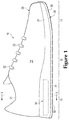
- FIG. 1-3 An article of footwear 10 is depicted in Figures 1-3 as including an upper 20 and a sole structure 30.
- footwear 10 may be divided into three general regions: a forefoot region 11, a midfoot region 12, and a heel region 13.
- Forefoot region 11 generally includes portions of footwear 10 corresponding with the toes and the joints connecting the metatarsals with the phalanges.
- Midfoot region 12 generally includes portions of footwear 10 corresponding with the arch area of the foot.
- Heel region 13 generally includes portions of footwear 10 corresponding with rear portions of the foot, including the calcaneus bone.
- Regions 11-13 are not intended to demarcate precise areas of footwear 10. Rather, regions 11-13 are intended to represent general areas of footwear 10 to aid in the following discussion. In addition to being applied to footwear 10, regions 11-13 may also be applied to upper 20, sole structure 30, and individual elements thereof.
- Footwear 10 also includes a lateral side 14 and a medial side 15. More particularly, lateral side 14 corresponds with an outside area of the foot (i.e. the surface that faces away from the other foot), and medial side 15 corresponds with an inside area of the foot (i.e., the surface that faces toward the other foot). Lateral side 14 and medial side 15 also extend through each of regions 11-13 and correspond with opposite sides of footwear 10. As with regions 11-13, sides 14 and 15 represent general areas of footwear 10 to aid in the following discussion, and may also be applied to upper 20, sole structure 30, and individual elements thereof, in addition to being applied to footwear 10.
- Upper 20 is depicted as having a substantially conventional configuration incorporating a plurality of material elements (e.g., textile, foam, leather, and synthetic leather) that are stitched, adhered, bonded, or otherwise joined together to form an interior void for securely and comfortably receiving a foot.
- the material elements may be selected and located with respect to upper 20 in order to selectively impart various properties to upper 20, such as durability, air-permeability, wear-resistance, flexibility, and comfort.
- An ankle opening 21 in heel region 13 provides access to the interior void.
- upper 20 may include a lace 22 that is utilized in a conventional manner to modify the dimensions of the interior void, thereby securing the foot within the interior void and facilitating entry and removal of the foot from the interior void.
- Lace 22 may extend through apertures in upper 20, and a tongue portion of upper 20 may extend between the interior void and lace 22.
- Upper 20 may also incorporate a sockliner 23 that is located within the void in upper 20 and adjacent a plantar (i.e., lower) surface of the foot to enhance the comfort of footwear 10.
- a plantar (i.e., lower) surface of the foot to enhance the comfort of footwear 10.
- upper 20 may exhibit the general configuration discussed above or the general configuration of practically any other conventional or non-conventional upper. Accordingly, the overall structure of upper 20 may vary significantly.
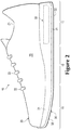
- Sole structure 30 is secured to upper 20 and has a configuration that extends between upper 20 and the ground. In effect, therefore, sole structure 30 is positioned to extend between the foot and the ground. In addition to attenuating ground reaction forces (such as by providing cushioning for the foot), sole structure 30 may provide traction, impart stability, and limit various foot motions, such as pronation.
- midsole 31 may incorporate a polymer foam material, such as polyurethane or ethylvinylacetate.
- Midsole 31 may also incorporate a fluid-filled chamber 33.
- midsole 31 may incorporate one or more other footwear elements that enhance the comfort, performance, or ground reaction force attenuation properties of footwear 10, including plates, moderators, lasting elements, or motion control members.
- Outsole 32 which may be absent in some configurations of footwear 10, is depicted as being secured to a lower surface of midsole 31 and forms at least part of a ground-contacting surface of footwear 10.
- Outsole 32 may be formed from a rubber material that provides a durable and wear-resistant surface for engaging the ground.
- outsole 32 may also be textured to enhance the traction (i.e., friction) properties between footwear 10 and the ground.
- outsole 32 may be secured to the polymer foam material alone, to chamber 33 alone, or to both the polymer foam material and chamber 33. In some configurations, outsole 32 may be absent from footwear 10.
- Chamber 33 is depicted as having a shape that fits within a perimeter of midsole 31 and is depicted as being primarily located in heel region 13. Accordingly, when the foot is located within upper 20, chamber 33 extends under a heel area of the foot (for example, under a calcaneus bone of the wearer) in order to attenuate ground reaction forces that are generated when sole structure 30 is compressed between the foot and the ground during various ambulatory activities, such as running and walking.
- chamber 33 may extend through alternate portions of footwear 10.
- chamber 33 may extend only through forefoot region 11, or only through midfoot region 12, or through substantially all of footwear 10 (i.e., from forefoot region 11 to heel region 13 and also from lateral side 14 to medial side 15).
- chamber 33 may extend only through lateral side 14 of footwear 10, or only through medial side 15 of footwear 10.
- Chamber 33 may also extend through any combination of regions and sides. In other words, in various configurations, chamber 33 may extend through any portion or portions of footwear 10.
- Chamber 33 is also depicted as being substantially surrounded by or entirely encapsulated within a polymer foam material of midsole 31 and secured to the polymer foam material.
- midsole 31 may otherwise incorporate chamber 33.
- chamber 33 may be partially encapsulated within the polymer foam material of midsole 31, or may be above the polymer foam material, or may be below the polymer foam material, or may be between layers or regions of one or more polymer foam materials.
- portions of chamber 33 may form an upper or lower surface of midsole 31.
- the polymer foam material of midsole 31 may be absent and chamber 33 may be secured to both upper 20 and outsole 32.
- a sidewall of midsole 31 is depicted as being formed substantially entirely by the polymer foam material of midsole 31, the sidewall may be otherwise formed in various other configurations of footwear 10.
- the sidewall of midsole 31 may be formed partially by the polymer foam material of midsole 31 and partially by portions of chamber 33. That is, one or more portions of chamber 33 may be exposed on sides 14 and 15 to form one or more portions of the sidewall.
- the sidewall of midsole 31 may be substantially entirely formed by exposed portions of chamber 33.
- chamber 33 may contact or be secured to one or more other footwear elements within midsole 31, such as plates, moderators, lasting elements, or motion control members. Accordingly, the overall shape of chamber 33 and the manner in which chamber 33 is incorporated into footwear 10 may vary significantly.
- chamber 33 may also be a component of a fluid system within footwear 10. More particularly, pumps, conduits, and valves may be joined with chamber 33 to provide a fluid system that pressurizes chamber 33 with air from the exterior of footwear 10 or a reservoir within footwear 10.
- chamber 33 may incorporate a valve or other structure that permits an individual, such as a wearer, to adjust the pressure of the fluid.
- chamber 33 may be utilized in combination with any of the fluid systems disclosed in U.S. Patent Number 7,210,249 to Passke, et al. and U.S. Patent Number 7,409,779 to Dojan, et al , including fluid systems that vary the pressure within chamber 33 depending upon, for example, the running style or weight of the wearer.
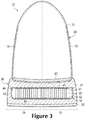
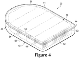
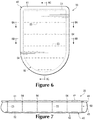
- Chamber 33 is depicted individually in Figures 4-8C as having a substantially flat configuration that is suitable for footwear applications.
- the primary elements of chamber 33 are a barrier 40 and a tensile element 50.
- Barrier 40 (a) forms an exterior of chamber 33, (b) defines an interior void that receives both a pressurized fluid and tensile element 50, and (c) provides a durable sealed barrier for retaining the pressurized fluid within chamber 33.
- An exterior surface of barrier 40 forms an outer surface of chamber 33, and an interior surface of barrier 40 defines the interior void.
- the polymer material of barrier 40 includes (a) a first barrier portion 41 oriented toward upper 20, which may form an upper portion of barrier 40, and (b) an opposite second barrier portion 42 oriented toward outsole 32, which may form a lower portion of barrier 40.
- Barrier 40 also includes a peripheral edge 43 that extends around a periphery of chamber 33 and between barrier portions 41 and 42, and a peripheral bond 44 that joins a periphery of first barrier portion 41 to a periphery of second barrier portion 42.
- Tensile element 50 is located within the interior void and between first barrier portion 41 and second barrier portion 42 and is accordingly incorporated into the interior void.
- Tensile element 50 includes (a) a first material layer 51, which may be an upper layer oriented toward upper 20, (b) an opposite second material layer 52, which may be a lower layer oriented toward the ground, and (c) a plurality of strand segments 53 in a plurality of rows 54.
- Material layers 51 and 52 are secured to the interior surface of barrier 40. More particularly, first material layer 51 is secured to a part of an interior surface of barrier 40 formed by first barrier portion 41, and second material layer 52 is secured to a part of the interior surface of barrier 40 formed by second barrier portion 42.
- tensile element 50 may be secured to barrier 40 in various ways, including thermobonding, adhesive bonding, or both.
- Strand segments 53 are portions of one or more strands (i.e., lengths of material having a generally one-dimensional structure) used to stitch, sew together, or otherwise join first material layer 51 to second material layer 52, as is discussed in greater detail below. Some strand segments 53 extend between material layers 51 and 52, thereby extending across the interior void. Other strand segments 53 extend (a) across a surface of first material layer 51 facing first barrier portion 41, and (b) across a surface of second material layer 52 facing second barrier portion 42. That is, various pluralities of strand segments 53 may extend (a) between first barrier portion 41 and first material layer 51, and (b) between second barrier portion 42 and second material layer 52.
- barrier 40 A wide range of polymer materials may be utilized for barrier 40. In selecting materials for barrier 40, engineering properties of the materials (e.g., tensile strength, stretch properties, fatigue characteristics, dynamic modulus, and loss tangent) as well as the ability of the materials to prevent the diffusion of the fluid contained by barrier 40 may be considered.
- barrier 40 When formed of thermoplastic urethane, for example, barrier 40 may have a thickness of approximately 1.0 millimeter, but the thickness may range from less than 0.25 to more than 2.0 millimeters, for example.
- examples of polymer materials that may be suitable for barrier 40 include polyurethane, polyester, polyester polyurethane, and polyether polyurethane.
- Barrier 40 may also be formed from a material that includes alternating layers of thermoplastic polyurethane and ethylene-vinyl alcohol copolymer, as disclosed in U.S. Patent Numbers 5,713,141 and 5,952,065 to Mitchell, et al. A variation upon this material may also be utilized, wherein a center layer is formed of ethylene-vinyl alcohol copolymer, layers adjacent to the center layer are formed of thermoplastic polyurethane, and outer layers are formed of a regrind material of thermoplastic polyurethane and ethylene-vinyl alcohol copolymer.
- Another suitable material for barrier 40 is a flexible microlayer membrane that includes alternating layers of a gas barrier material and an elastomeric material, as disclosed in U.S.
- chamber 33 may be formed from various sheets of a polymer material, each of the sheets including multiple layers of different polymer materials. Additional suitable materials are disclosed in U.S. Patent Numbers 4,183,156 and 4,219,945 to Rudy . Further suitable materials include thermoplastic films containing a crystalline material, as disclosed in U.S. Patent Numbers 4,936,029 and 5,042,176 to Rudy , and polyurethane including a polyester polyol, as disclosed in U.S. Patent Numbers 6,013,340 , 6,203,868 , and 6,321,465 to Bonk, et al.
- a variety of processes may be utilized to manufacture chamber 33.
- the manufacturing processes involve (a) securing a pair of polymer sheets, which form barrier portions 41 and 42 as well as peripheral edge 43, to tensile element 50 and (b) forming peripheral bond 44 to extend around peripheral edge 43 and join the polymer sheets.
- Peripheral bond 44 is depicted as being adjacent to the upper surface of chamber 33, but in various other configurations it may be positioned between the upper and lower surfaces of chamber 33, or it may be adjacent to the lower surface of chamber 33.
- the manufacturing process may also position tensile element 50 within chamber 33 and bond tensile element 50 to barrier portions 41 and 42.
- substantially all of the thermoforming process may be performed with a mold, as described in greater detail below, each of the various parts or steps of the process may be performed separately in forming chamber 33. That is, a variety of other methods may be utilized to form chamber 33.
- a supplemental polymer material may be added to or incorporated within tensile element 50.
- the supplemental polymer material may soften, melt, or otherwise begin to change state so that contact with barrier portions 41 and 42 induces material from barrier 40 to intermingle or otherwise join with the supplemental polymer material.
- the supplemental polymer material may be permanently joined with barrier 40, thereby joining tensile element 50 with barrier 40.
- thermoplastic threads or strips may be present within tensile element 50 to facilitate bonding with barrier 40, as disclosed, for example, in U.S. Patent Number 7,070,845 to Thomas, et al. , or an adhesive may be utilized to secure barrier 40 and tensile element 50.
- a fluid may be injected into the interior void and pressurized between zero and three-hundred-fifty kilopascals (i.e., approximately fifty-one pounds per square inch) or more.
- the pressurized fluid exerts an outward force upon barrier 40, which tends to separate barrier portions 41 and 42.
- tensile element 50 being secured to each of barrier portions 41 and 42, operates to retain the intended shape of chamber 33 when pressurized. More particularly, strand segments 53 extending across the interior void are placed in tension by the outward force of the pressurized fluid upon barrier 40, thereby preventing barrier 40 from expanding outward and causing chamber 33 to retain an intended shape.
- tensile element 50 prevents barrier 40 from expanding outward or otherwise distending due to the pressure of the fluid. That is, tensile element 50 effectively limits the expansion of chamber 33 to retain an intended shape of barrier portions 41 and 42.
- FIG. 9 depicts a spacing structure 100 suitable for use in forming tensile element 50.
- Spacing structure 100 includes a first surface 101, which may be an upper surface, and an opposite second surface 102, which may be a lower surface. In addition, a number of side surfaces 103 that extend between first surface 101 and second surface 102.
- Spacing structure 100 includes a plurality of support portions 104 separated by a plurality of gaps 105. In some configurations, as depicted in Figure 9 , spacing structure 100 may have a comb-like configuration, with support portions 104 extending in a substantially aligned and parallel direction that resembles the fingers of a comb.
- first material layer 51, second material layer 52, and spacing structure 100 may be stacked.
- a stitching step which may be performed by a sewing or stitching machine, by hand, or by another method of forming stitches
- one or more strands of material that form strand segments 53 may be used to join the first material layer to the second material layer, thereby forming tensile element 50 from first material layer 51, second material layer 52, and the strand or strands.
- spacing structure 100 may be removed after the stitching step, and first material layer 51 may be spaced from second material layer 52.
- various pluralities of strand segments 53 are positioned throughout tensile element 50.
- Strand segments 53 are segments of the material strand or strands stitched through material layers 51 and 52. Some strand segments 53 extend between material layers 51 and 52. Other strand segments 53 extend across outwardly-facing surfaces of material layers 51 and 52.
- a plurality of rows 54 of strand segments 53 are positioned throughout tensile element 50.
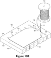
- Figures 10A-10D schematically depict steps in a process for manufacturing tensile element 50.
- material layers 51 and 52 and spacing structure 100 are stacked such that spacing structure 100 is located between first material layer 51 and second material layer 52.
- a needle 111 stitches, sews, or otherwise draws a strand 110 from a spool 120, through first material layer 51, through a gap 105 between support portions 104, and through second material layer 52.
- Strand 110 is then stitched, sewn, or otherwise drawn back through second material layer 52, gap 105, and first material layer 51.
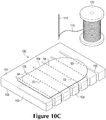
- Needle 111 is then moved to a nearby position on first material layer 51 and drawn in another loop, course, or stitch back through material layers 51 and 52, and so on, until a row 54 of strand segments 53 extends across tensile element 50, as depicted in Figure 10B .
- First material layer 51 and second material layer 52 may accordingly be joined by a row 54 of strand segments 53 or stitches.
- strand 110 may be stitched in a direction substantially perpendicular to or angled with respect to the direction in which support portions 104 and gaps 105 extend. That is, rows 54 may extend across one or more support portions 104 and through a plurality of gaps 105.
- each of rows 54 may be formed from a separate or distinct portion of strand 110.
- strand 110 may extend across a support portion 104 at the end of one row 54 and form the beginning of another row 54, such that some or all of rows 54 may be formed from a single, contiguous portion of strand 110.
- spacing structure 100 is removed, and tensile element 50 is provided with a plurality of strand segments 53 that extend between material layers 51 and 52.
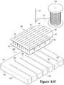
- Figures 11A-11F schematically depict steps in another process for manufacturing tensile element 50.
- first material layer 51 and second material layer 52 are stacked, with first material layer 51 being in contact with second material layer 52.
- Material layers 51 and 52 are then stacked with spacing structure 100 such that first material layer 51 is located between second material layer 52 and spacing structure 100, i.e., such that both material layers 51 and 52 are on the same side of spacing structure 100.
- Needle 111 then stitches, sews, or otherwise draws strand 110 from spool 120, through a gap 105 between support portions 104, through first material layer 51, and through second material layer 52.
- Strand 110 is then stitched, sewn, or otherwise drawn back through second material layer 52, first material layer 51, and the gap 105, creating a stitch joining first material layer 51 and second material layer 52, as depicted in Figure 11B .
- Needle 111 is then moved over a support portion 104, positioned at an adjacent gap 105, and drawn in another loop, course, or stitch back through material layers 51 and 52 and over another support portion 104, and so on, until a row 54 of strand segments 53 or stitches extends across a plurality of support portions 104, as depicted in Figure 11C .
- Strand 110 has been stitched in a direction substantially perpendicular to the direction in which support portions 104 and gaps 105 extend. That is, rows 54 primarily extend through a plurality of gaps 105 and a plurality of support portions 104.
- each of rows 54 may be formed from a separate or distinct portion of strand 110, or some or all of rows 54 may be formed from a single, contiguous portion of strand 110.
- spacing structure 100 is removed. At this stage, portions of strand 110 form loops.
- First material layer 51 is then spaced from second material layer 52, as depicted in Figure 11F , to provide tensile element 50 with a plurality of strand segments 53 positioned to extend between material layers 51 and 52.
- Strand 110 (and, in turn, portions of strand 110 such as strand segments 53) may be formed to include any of a variety of materials and may have any of a variety of generally one-dimensional structures.
- the term "one-dimensional structure" or variants thereof is intended to encompass generally elongate structures exhibiting a length that is substantially greater than a width and a thickness.
- the thickness of strand 110 may vary significantly to range from less than 0.03 millimeters to more than 5 millimeters, for example.
- one-dimensional structures will often have a cross-section where width and thickness are substantially equal (e.g., a round or square cross-section)
- some one-dimensional structures may have a width that is greater than a thickness (e.g., a rectangular, oval, or otherwise elongate cross-section).
- a structure may be considered one-dimensional if a length of the structure is substantially greater than a width and a thickness of the structure.
- Suitable materials for strand 110 include rayon, nylon, polyester, polyacrylic, silk, cotton, carbon, glass, aramids (e.g., para-aramid fibers and meta-aramid fibers), ultra high molecular weight polyethylene, liquid crystal polymer, copper, aluminum, and steel.
- Suitable generally one-dimensional structures for strand 110 include filaments, fibers, yarns, threads, cables, or rope. Whereas filaments have an indefinite length and may be utilized individually as strands, fibers have a relatively short length and generally go through spinning or twisting processes to produce a strand of suitable length.
- An individual filament utilized in strand 110 may be formed form a single material (i.e., a monocomponent filament) or from multiple materials (i.e., a bicomponent filament). In addition, different filaments may be formed from different materials. As an example, yarns utilized as strand 110 may include filaments that are each formed from a common material, may include filaments that are each formed from two or more different materials, or may include filaments that are each formed from two or more different materials. Yarns utilized as strand 110 may also include individual fibers formed from a single material, individual fibers formed from multiple materials, or different fibers formed from different materials. Similar concepts also apply to threads, cables, or ropes.
- Material layers 51 and 52 may be formed of, or may be formed to include, a variety of materials.
- Material layers 51 and 52 may be formed to include various types of textiles, such as knitted textiles, woven textiles, non-woven textiles, spacer textiles, or mesh textiles, and may include various types of materials, such as rayon, nylon, polyester, polyacrylic, elastane, cotton, wool, or silk.
- the textiles may be substantially non-stretch, or may exhibit significant one-dimensional stretch, or may exhibit significant multi-directional stretch.
- Material layers 51 and 52 may also be formed to include supplemental polymer layers, polymer sheets, or synthetic leather, for example. Additionally, either of material layers 51 and 52 could be formed of combinations of materials, such as composite layers including both a textile material or layer and a polymer material or sheet.
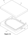
- a mold 60 that may be utilized in the thermoforming process is depicted as including a first mold portion 61 and a second mold portion 62. Mold 60 is utilized to form chamber 33 from a pair of polymer sheets that are molded and bonded to define barrier portions 41 and 42 as well as peripheral edge 43, and the thermoforming process secures tensile element 50 within barrier 40.
- mold 60 (a) imparts shape to one of the polymer sheets in order to form first barrier portion 41, (b) imparts shape to the other of the polymer sheets in order to form second barrier portion 42, (c) imparts shape to one or both of the polymer sheets in order to form peripheral edge 43, (d) joins and seals the polymer sheets at peripheral bond 44, and (e) bonds tensile element 50 to each of barrier portions 41 and 42.
- various components forming chamber 33 may be obtained and organized.
- tensile element 50 may be formed and, if necessary, cut to a shape generally corresponding with the shapes of various features of mold portions 61 and 62.
- a first polymer sheet 71 and a second polymer sheet 72 may be used to form barrier 40.
- Tensile element 50 may be positioned between first polymer sheet 71 and second polymer sheet 72.
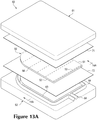
- the various components of chamber 33 are located between mold portions 61 and 62, as depicted in Figures 13A and 14A .
- a shuttle frame or other device may be utilized.
- the various components of chamber 33 are heated to a temperature that facilitates bonding between the components.
- suitable temperatures may range from 120 to 200 degrees Celsius (248 to 392 degrees Fahrenheit) or more.
- Various radiant heaters or other devices may be utilized to heat the various components of chamber 33.
- mold 60 may be heated such that contact between mold 60 and the various components of chamber 33 raises the temperature of the components to a level that facilitates bonding.
- the various components of chamber 33 such as one or more of polymer sheets 71 and 72 and tensile element 50, may be heated before being located between mold portions 61 and 62.
- mold portions 61 and 62 translate toward each other and begin to close upon the components such that (a) first mold portion 61 contacts first polymer sheet 71, and (b) ridge 64 of second mold portion 62 contacts second polymer sheet 72.
- first polymer sheet 71 may be brought closer to first material layer 51 of tensile element 50
- polymer layer 72 may be brought closer to second material layer 52 of tensile element 50.
- Air may then be partially evacuated from the area around polymer sheets 71 and 72 through various vacuum ports in mold portions 61 and 62.
- the purpose of evacuating the air is to draw polymer sheets 71 and 72 into contact with the various contours of mold 60. This ensures that polymer sheets 71 and 72 are properly shaped in accordance with the contours of mold 60.
- polymer sheets 71 and 72 may stretch in order to extend around tensile element 50 and into mold 60.
- the thickness of polymer sheets 71 and 72 before being compressed between mold portions 61 and 62 may be greater than the thickness of the corresponding portions of barrier 40 after the manufacture of chamber 33 has been completed. This difference between the original thicknesses of polymer sheets 71 and 72 and the resulting thickness of barrier 40 may occur as a result of the stretching taking place at this stage of the thermoforming process.
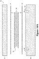
- Mold portions 61 and 62 may compress and place a specific degree of pressure upon the components, thereby bonding and securing polymer sheets 71 and 72 to opposite surfaces of tensile element 50. More specifically, first polymer sheet 71 may be thermobonded to first material layer 51 of tensile element 50. Similarly, second polymer sheet 72 may be thermobonded to second material layer 52 of tensile element 50. Second mold portion 62 includes a peripheral cavity 63 that forms peripheral edge 43 from second polymer layer 72. As depicted in Figures 12-14D , polymer sheets 71 and 72 are thermobonded to tensile element 50, but in other manufacturing processes, polymer sheets 71 and 72 may at least partially be otherwise secured to tensile element 50. For example, polymer sheets 71 and 72 may at least partially be secured to tensile element 50 by an adhesive, or by use of thermoplastic threads or strips, as disclosed in U.S. Patent Number 7,070,845 to Thomas, et al.
- thermobonding or variants thereof is defined as a securing technique between two elements that involves a softening or melting of a thermoplastic polymer material within at least one of the elements such that the materials of the elements are secured to each other when cooled.
- thermobond or variants thereof is defined as the bond, link, or structure that joins two elements through a process that involves a softening or melting of a thermoplastic polymer material within at least one of the elements such that the materials of the elements are secured to each other when cooled.
- Thermobonding may involve, for example, the melting or softening of thermoplastic materials within each of two or more elements to join the elements. Accordingly, thermobonding may create a polymer bond (i.e., a thermobond between a polymer material of one element and a polymer material of another element).
- Thermobonding does not generally involve the use of stitching or adhesives, but involves directly bonding elements to each other with heat. In some situations, however, stitching or adhesives may be utilized to supplement the thermobond or the joining of elements through thermobonding. For example, as an alternative to thermobonding, or in addition to thermobonding, an adhesive, a thermally-activated adhesive, or other securing structure may be utilized in joining the elements.
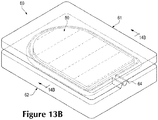
- first mold portion 61 and ridge 64 bond first polymer sheet 71 to second polymer sheet 72, as depicted in Figures 13B and 14B , thereby forming peripheral bond 44 and an interior void between polymer sheets 71 and 72. Furthermore, portions of ridge 64 that extend away from tensile element 50 form a bond between other areas of polymer sheets 71 and 72, contributing to the formation of an inflation conduit 73.
- the area between polymer sheets 71 and 72 and proximal to tensile element 50 may be pressurized.
- an injection needle may be located between polymer sheets 71 and 72, and the injection needle may be located such that ridge 64 envelops the injection needle when mold 60 closes.
- a gas may then be ejected from the injection needle such that polymer sheets 71 and 72 engage ridge 64.
- Inflation conduit 73 may thereby be formed between polymer sheets 71 and 72 (see Figure 13C ).
- the gas may then pass through inflation conduit 73, thereby entering and pressurizing the area proximal to tensile element 50 and between polymer sheets 71 and 72.
- the internal pressure ensures that polymer sheets 71 and 72 contact the various surfaces of mold 60.
- a supplemental layer of a polymer material or thermoplastic threads may be added to or incorporated within tensile element 50 in order to facilitate bonding between tensile element 50 and barrier 40.
- the pressure exerted upon the components by mold portions 61 and 62 may ensure that the supplemental layer or thermoplastic threads form a bond with polymer sheets 71 and 72.
- mold 60 is opened and the various components of chamber 33 and excess portions of polymer sheets 71 and 72 are permitted to cool, as depicted in Figures 13C and 14C .
- a fluid may be injected into the interior void through an inflation needle and inflation conduit 73.
- tensile element 50 remains in a compressed configuration.
- the various components of chamber 33 are pressurized, however, the fluid places an outward force upon barrier 40, which tends to separate barrier portions 41 and 42, thereby placing tensile element 50 in tension. More specifically, strand segments 53 extending between first material layer 51 and second material layer 52 are placed in tension, as is the portion of strand 110 comprising all the strand segments 53 of a particular row 54.
- chamber 33 is described above and depicted in Figures 4-8C , and although various exemplary processes for manufacturing tensile element 50 are described above and depicted in Figure 9-11F , these configurations of chamber 33 and processes for manufacturing tensile element 50 are initial configurations. Other configurations are possible.
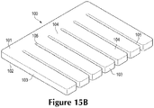
- spacing structure 100 and tensile element 50 may have a range of configurations.
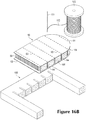
- spacing structure 100 may have any of a variety of heights, such as the relatively taller height depicted in Figure 15A , or the relatively shorter height depicted in Figure 15B .
- spacing structure 100 may have any of a range of widths or lengths, including a width shorter than or substantially equal to the width of material layer 51 or 52, or a length shorter than or substantially equal to the length of material layer 51 or 52.
- spacing structure 100 is depicted in Figures 9-11F as having a comb-like structure bounded by a substantially rectangular shape. In various other configurations, spacing structure 100 may be bounded by any of a range of shapes, including regular geometric shapes such as squares, circles, triangles, and hexagons, as well as any other shape, regular or irregular, including shapes corresponding with alternate portions of a foot. Similarly, although depicted as having a shape similar to heel region 13 of footwear 10, material layers 51 and 52 may have any of a range of shapes, including regular geometric shapes as well as any other shape, regular or irregular, including shapes corresponding with alternate portions of a foot.
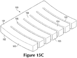
- spacing structure 100 has support portions 104 and gaps 105 that are substantially linear and have substantially uniform width.
- support portions 104 and gaps 105 may be otherwise configured.
- support portions 104 and gaps 105 may be substantially curved.
- support portions 104 and gaps 105 may have non-uniform width, such that their width near one side of spacing structure 100 is substantially greater than their width near an opposite side of spacing structure 100.
- spacing structure 100 In the comb-like structure depicted in Figures 9-11F , all the support portions 104 of spacing structure 100 extend away from a side of spacing structure 100, such that spacing structure 100 has a unitary or one-piece configuration.
- Other configurations of spacing structure 100 are possible.
- spacing structure 100 in Figure 15E has a two-piece configuration including two portions resembling comb-like structures having interlocking fingers.
- some support portions 104 of spacing structure 100 may be part of one unitary or one-piece portion of spacing structure 100, whereas other support portions 104 of spacing structure 100 may be part of another unitary or one-piece portion of spacing structure 100.
- support portions 104 of spacing structure 100 may include any number of unitary or one-piece portions.
- spacing structure 100 includes support portions 104 that extend away from a side of a unitary or one-piece portion of spacing structure 100, and spacing structure 100 also includes a plurality of support portions 104 that are self-contained unitary or one-piece portions of spacing structure 100.
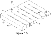
- spacing structure 100 as well as support portions 104 and gaps 105 may have non-uniform heights that may impart a non-uniform contour to spacing structure 100, and may accordingly also impart a non-uniform structure to tensile element 50.
- spacing structure 100 has a greater height at a first end than at a second end, and substantially linearly decreases in height from the first end to the second end, which imparts a substantially linear decrease in height to support portions 104 and gaps 105.
- spacing structure 100 may impart a tapered configuration to tensile element 50.
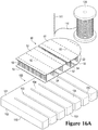
- spacing structure 100 includes two one-piece or unitary portions, each portion having a comb-like configuration, and the fingers of the two comb-like portions extending away from a side of each portion and toward each other.
- the two comb-like portions of spacing structure 100 cooperatively define a depression within first surface 101 of spacing structure 100.
- spacing structure 100 may impart a heel cup to tensile element 50, as depicted in cross-section in Figure 17A .
- first surface 101, second surface 102, and side surfaces 103 of spacing structure 100 may have any of a variety of non-planar contours, which may in turn impart corresponding non-planar contours to tensile element 50.
- Figures 9-11F depict each of material layers 51 and 52 as having unitary or one-piece configurations.
- material layers 51 and 52 may be otherwise configured to have any number of unitary or one-piece portions.
- first material layer 51 is depicted as having two one-piece portions
- second material layer 52 is depicted as having three one-piece portions.
- either material layer 51 or 52 may have any of a number of one-piece portions, each of which may have any of a range of shapes, including regular geometric shapes as well as any other shape, regular or irregular.
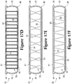
- Figure 10D depicts spacing structure 100 as having been removed, portions of spacing structure 100, or all of spacing structure 100, may remain within tensile element 50.
- a plurality of remainder portions 106 of spacing structure 100 (which has been formed to include a foam material) have been left within tensile element 50.
- Figure 16C depicts alternate remainder portions 106 that have been left within tensile element 50, each remainder portion 106 being a peripheral or outer part of each of support portions 104.
- tensile element 50 has strand segments 53 configured to extend between first material layer 51 and second material layer 52 in a particular way.
- strand segments 53 may extend between material layers 51 and 52 in other ways.
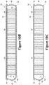
- strand segments 53 within a particular row 54 may be relatively less densely packed, as depicted in Figure 17B , or may be relatively more densely packed, as depicted in Figure 17C .
- Figures 4-8C depict five rows 54 of strand segments 53 spanning tensile element 50, different numbers of rows 54 may span tensile element 50.
- Figure 18A depicts three relatively less densely packed rows 54 spanning tensile element 50
- Figure 18B depicts nineteen relatively more densely packed rows 54 spanning tensile element 50.
- FIGS 9-11F depict tensile element 50 as being formed using a relatively simple stitching technique, such as a running stitch technique.
- a relatively simple stitching technique such as a running stitch technique.
- stitching or sewing techniques may be employed, by hand or by machine, such as a double running stitching technique, a lockstitching technique, an overlock stitching technique, or any other stitching technique.
- more than one strand 110 or portion of strand 110 may be used to form the stitches in a particular row 54.
- two portions of strand 110 are used to form row 54 of stitches, an additional strand 110 forms stitches that complement the first strand 110.
- both strands 110 are in tension, and each strand 110 extends through both first material layer 51 and second material layer 52.
- one strand 110 extends through only first material layer 51, and another strand 110 extends through only second material layer 52. Both strands 110 are interlocked with each other in the interior void of chamber 33, between material layers 51 and 52, and may thereby be placed in tension upon pressurization of chamber 33.
- Various stitching techniques are also possible in other configurations of the manufacturing process.
- Figure 17F depicts an alternate simple stitching or sewing technique
- Figure 17G depicts a technique in which first material layer 51 is joined to second material layer 52 with a plurality of strands, and a separate strand is used to form each of a plurality of stitches.
- tensile element 50 and barrier 40 are depicted as being separate elements, they may be more integrally related in some configurations of the manufacturing process.
- the material used for first material layer 51 is first polymer sheet 71
- the material used for second material layer 52 is second polymer sheet 72.
- part or all of first barrier portion 41 is first material layer 51
- part or all of second barrier portion 42 is second material layer 52.
- various pluralities of strand segments 53 may extend (a) across an outward-facing surface of first barrier portion 41, and (b) across an outward-facing surface of second barrier portion 42.
Landscapes
- Engineering & Computer Science (AREA)
- Mechanical Engineering (AREA)
- Textile Engineering (AREA)
- Footwear And Its Accessory, Manufacturing Method And Apparatuses (AREA)
- Filling Or Discharging Of Gas Storage Vessels (AREA)
- Pressure Vessels And Lids Thereof (AREA)
Applications Claiming Priority (3)
| Application Number | Priority Date | Filing Date | Title |
|---|---|---|---|
| US13/839,747 US9339080B2 (en) | 2013-03-15 | 2013-03-15 | Method of manufacturing a fluid-filled chamber with a tensile element |
| EP14731409.0A EP2967196B1 (de) | 2013-03-15 | 2014-03-13 | Verfahren zur herstellung einer flüssigkeitsgefüllten kammer mit zugelement |
| PCT/US2014/025178 WO2014151186A2 (en) | 2013-03-15 | 2014-03-13 | Method of manufacturing a fluid-filled chamber with a tensile element |
Related Parent Applications (2)
| Application Number | Title | Priority Date | Filing Date |
|---|---|---|---|
| EP14731409.0A Division EP2967196B1 (de) | 2013-03-15 | 2014-03-13 | Verfahren zur herstellung einer flüssigkeitsgefüllten kammer mit zugelement |
| EP14731409.0A Division-Into EP2967196B1 (de) | 2013-03-15 | 2014-03-13 | Verfahren zur herstellung einer flüssigkeitsgefüllten kammer mit zugelement |
Publications (2)
| Publication Number | Publication Date |
|---|---|
| EP3360437A1 true EP3360437A1 (de) | 2018-08-15 |
| EP3360437B1 EP3360437B1 (de) | 2021-01-13 |
Family
ID=50977043
Family Applications (2)
| Application Number | Title | Priority Date | Filing Date |
|---|---|---|---|
| EP18162205.1A Active EP3360437B1 (de) | 2013-03-15 | 2014-03-13 | Verfahren zur herstellung einer flüssigkeitsgefüllten kammer mit zugelement |
| EP14731409.0A Active EP2967196B1 (de) | 2013-03-15 | 2014-03-13 | Verfahren zur herstellung einer flüssigkeitsgefüllten kammer mit zugelement |
Family Applications After (1)
| Application Number | Title | Priority Date | Filing Date |
|---|---|---|---|
| EP14731409.0A Active EP2967196B1 (de) | 2013-03-15 | 2014-03-13 | Verfahren zur herstellung einer flüssigkeitsgefüllten kammer mit zugelement |
Country Status (4)
| Country | Link |
|---|---|
| US (4) | US9339080B2 (de) |
| EP (2) | EP3360437B1 (de) |
| CN (2) | CN105120700B (de) |
| WO (1) | WO2014151186A2 (de) |
Families Citing this family (25)
| Publication number | Priority date | Publication date | Assignee | Title |
|---|---|---|---|---|
| US11039662B2 (en) * | 2009-12-03 | 2021-06-22 | Nike, Inc. | Tethered fluid-filled chamber with multiple tether configurations |
| US9339080B2 (en) | 2013-03-15 | 2016-05-17 | Nike, Inc. | Method of manufacturing a fluid-filled chamber with a tensile element |
| US9427043B2 (en) | 2013-10-31 | 2016-08-30 | Nike, Inc. | Fluid-filled chamber with stitched tensile member |
| USD767263S1 (en) * | 2015-02-17 | 2016-09-27 | Austin J. Reiser | Fillable shoe sole |
| USD765361S1 (en) * | 2015-03-16 | 2016-09-06 | Nike, Inc. | Shoe midsole |
| US10441027B2 (en) | 2015-10-02 | 2019-10-15 | Nike, Inc. | Footwear plate |
| KR102208854B1 (ko) | 2015-10-02 | 2021-01-28 | 나이키 이노베이트 씨.브이. | 신발류를 위한 발포체를 갖는 플레이트 |
| JP7240876B2 (ja) | 2015-10-02 | 2023-03-16 | ナイキ イノベイト シーブイ | 履物のための板 |
| USD798553S1 (en) * | 2015-12-18 | 2017-10-03 | Nike, Inc. | Shoe midsole |
| USD793680S1 (en) * | 2015-12-18 | 2017-08-08 | Nike, Inc. | Shoe midsole |
| WO2018017885A1 (en) | 2016-07-20 | 2018-01-25 | Nike Innovate C.V. | Footwear plate |
| CN113261746B (zh) * | 2016-07-20 | 2023-02-17 | 耐克创新有限合伙公司 | 鞋板 |
| US10524538B2 (en) | 2016-09-08 | 2020-01-07 | Nike, Inc. | Flexible fluid-filled chamber with tensile member |
| KR102295998B1 (ko) * | 2017-05-23 | 2021-09-02 | 나이키 이노베이트 씨.브이. | 단계화된 압축 강도를 갖는 돔형 중창 |
| EP3654797B1 (de) | 2018-04-16 | 2023-08-02 | NIKE Innovate C.V. | Laufsohlenplatte |
| US11344078B2 (en) | 2018-04-16 | 2022-05-31 | Nike, Inc. | Outsole plate |
| USD856646S1 (en) * | 2018-05-17 | 2019-08-20 | Nike, Inc. | Shoe |
| US20200121022A1 (en) | 2018-10-19 | 2020-04-23 | Nike, Inc. | Footwear sole structure having a composite element and methods for manufacturing same |
| USD929100S1 (en) * | 2021-01-13 | 2021-08-31 | Nike, Inc. | Cushioning device for footwear |
| USD929725S1 (en) * | 2021-01-13 | 2021-09-07 | Nike, Inc. | Cushioning device for footwear |
| USD929723S1 (en) * | 2021-01-13 | 2021-09-07 | Nike, Inc. | Cushioning device for footwear |
| USD929724S1 (en) * | 2021-01-13 | 2021-09-07 | Nike, Inc. | Cushioning device for footwear |
| USD929726S1 (en) * | 2021-01-13 | 2021-09-07 | Nike, Inc. | Cushioning device for footwear |
| US12179411B2 (en) | 2021-10-15 | 2024-12-31 | Nike, Inc. | System and method for forming textured bladder |
| CN119173169A (zh) * | 2022-05-11 | 2024-12-20 | 耐克创新有限合伙公司 | 具有外部增强流体填充囊的鞋类 |
Citations (14)
| Publication number | Priority date | Publication date | Assignee | Title |
|---|---|---|---|---|
| US4183156A (en) | 1977-01-14 | 1980-01-15 | Robert C. Bogert | Insole construction for articles of footwear |
| DE2855268A1 (de) * | 1978-12-21 | 1980-07-10 | Metzeler Kautschuk | Aufblasbares element fuer eine schuhsohle |
| US4219945A (en) | 1978-06-26 | 1980-09-02 | Robert C. Bogert | Footwear |
| US4936029A (en) | 1989-01-19 | 1990-06-26 | R. C. Bogert | Load carrying cushioning device with improved barrier material for control of diffusion pumping |
| US5042176A (en) | 1989-01-19 | 1991-08-27 | Robert C. Bogert | Load carrying cushioning device with improved barrier material for control of diffusion pumping |
| US5475904A (en) * | 1991-07-03 | 1995-12-19 | Le Roy; Guy | Method and device for producing composite laps and composites thereby obtained |
| US5713141A (en) | 1994-08-31 | 1998-02-03 | Nike, Inc. | Cushioning device with improved flexible barrier membrane |
| US6013340A (en) | 1995-06-07 | 2000-01-11 | Nike, Inc. | Membranes of polyurethane based materials including polyester polyols |
| US6082025A (en) | 1998-09-11 | 2000-07-04 | Nike, Inc. | Flexible membranes |
| US6127026A (en) | 1998-09-11 | 2000-10-03 | Nike, Inc. | Flexible membranes |
| US6321465B1 (en) | 1995-06-07 | 2001-11-27 | Nike, Inc. | Membranes of polyurethane based materials including polyester polyols |
| US7070845B2 (en) | 2003-08-18 | 2006-07-04 | Nike, Inc. | Fluid-filled bladder for an article of footwear |
| US7210249B2 (en) | 2001-06-21 | 2007-05-01 | Nike, Inc. | Footwear with bladder filter |
| US7409779B2 (en) | 2005-10-19 | 2008-08-12 | Nike, Inc. | Fluid system having multiple pump chambers |
Family Cites Families (33)
| Publication number | Priority date | Publication date | Assignee | Title |
|---|---|---|---|---|
| US2968105A (en) | 1959-03-03 | 1961-01-17 | Olympio C Rizzo | Pneumatic jump boot construction |
| US3526199A (en) * | 1967-12-22 | 1970-09-01 | Borg Warner | Inflatable structure |
| GB1394824A (en) * | 1971-06-09 | 1975-05-21 | Ici Ltd | Production of laminated products |
| US4462331A (en) | 1983-01-31 | 1984-07-31 | The United States Of America As Represented By The Secretary Of The Navy | Inflatable bottom construction for inflatable boat |
| US5083361A (en) * | 1988-02-05 | 1992-01-28 | Robert C. Bogert | Pressurizable envelope and method |
| CA1338369C (en) | 1988-02-24 | 1996-06-11 | Jean-Pierre Vermeulen | Shock absorbing system for footwear application |
| US4914836A (en) * | 1989-05-11 | 1990-04-10 | Zvi Horovitz | Cushioning and impact absorptive structure |
| US5118555A (en) | 1989-05-11 | 1992-06-02 | Zvi Horovitz | Composite article |
| US5022109A (en) * | 1990-06-11 | 1991-06-11 | Dielectrics Industries | Inflatable bladder |
| CA2120030C (en) | 1991-09-26 | 2002-01-22 | Joseph J. Skaja | Shoe sole component and shoe sole component construction method |
| DE69521311D1 (de) * | 1995-07-27 | 2001-07-19 | Zodiac International Issy Les | Wahrnehmbar steifes, thermisch isolierendes Paneel, sowie Verfahren zu seiner Herstellung |
| US5836357A (en) * | 1995-10-26 | 1998-11-17 | Bay Mills Ltd. | Pressure-expandable conduit liner |
| US20020121031A1 (en) | 1998-01-30 | 2002-09-05 | Steven Smith | 2a improvements |
| DE10026405B4 (de) * | 1999-05-31 | 2008-02-21 | Cetex Chemnitzer Textilmaschinenentwicklung Ggmbh | Abstandsgewirke und Vorrichtung zu seiner Herstellung |
| US6519797B1 (en) | 1999-08-10 | 2003-02-18 | Dynamic Contours Llc | Self adjusting, contouring cushioning system |
| US6402879B1 (en) | 2000-03-16 | 2002-06-11 | Nike, Inc. | Method of making bladder with inverted edge seam |
| US6385864B1 (en) | 2000-03-16 | 2002-05-14 | Nike, Inc. | Footwear bladder with controlled flex tensile member |
| US20050167029A1 (en) * | 2001-11-26 | 2005-08-04 | Nike, Inc. | Method of thermoforming a fluid-filled bladder |
| US6837951B2 (en) | 2001-11-26 | 2005-01-04 | Nike, Inc. | Method of thermoforming a bladder structure |
| US20030097767A1 (en) | 2001-11-28 | 2003-05-29 | Perkinson Jermaine Derelle | 4-E.V.A system |
| GB0316192D0 (en) * | 2003-07-11 | 2003-08-13 | Univ Leeds | Hydro link spacer fabrics |
| US20060086003A1 (en) | 2004-10-22 | 2006-04-27 | Yu-Sheng Tseng | Shoe sole with air cushion |
| US7451554B2 (en) | 2005-10-19 | 2008-11-18 | Nike, Inc. | Fluid system having an expandable pump chamber |
| KR100808475B1 (ko) | 2006-04-13 | 2008-03-03 | 김월성 | 에어 매트리스 |
| TW200940415A (en) * | 2008-03-21 | 2009-10-01 | Chieh-Hua Liao | Air sealed object without thermal resistant material and manufacturing method thereof |
| US8943709B2 (en) * | 2008-11-06 | 2015-02-03 | Nike, Inc. | Article of footwear with support columns having fluid-filled bladders |
| GB0822110D0 (en) * | 2008-12-03 | 2009-01-07 | Angiomed Ag | Catheter sheath for implant delivery |
| WO2010114194A1 (ko) * | 2009-03-31 | 2010-10-07 | 코오롱글로텍주식회사 | 건축용 섬유 내외장재 |
| US8425712B2 (en) * | 2010-04-07 | 2013-04-23 | Nike, Inc. | Method of manufacturing cushioning elements for apparel and other products |
| JP5341961B2 (ja) * | 2011-08-08 | 2013-11-13 | 株式会社ゴタリオ | 縫製品、及び生地の縫製方法 |
| US9339080B2 (en) * | 2013-03-15 | 2016-05-17 | Nike, Inc. | Method of manufacturing a fluid-filled chamber with a tensile element |
| WO2016164551A1 (en) * | 2015-04-08 | 2016-10-13 | Nike Innovate C.V. | Method of manufacturing a bladder element with an etched feature and article having a bladder element with an etched feature |
| DE102016225335B4 (de) * | 2016-12-16 | 2020-02-06 | Adidas Ag | Sohle für einen Schuh, Verfahren und Vorrichtung zu deren Herstellung sowie Schuh mit einer solchen Sohle |
-
2013
- 2013-03-15 US US13/839,747 patent/US9339080B2/en active Active
-
2014
- 2014-03-13 EP EP18162205.1A patent/EP3360437B1/de active Active
- 2014-03-13 CN CN201480014409.7A patent/CN105120700B/zh active Active
- 2014-03-13 CN CN201710696722.9A patent/CN107618200B/zh active Active
- 2014-03-13 WO PCT/US2014/025178 patent/WO2014151186A2/en not_active Ceased
- 2014-03-13 EP EP14731409.0A patent/EP2967196B1/de active Active
-
2016
- 2016-04-20 US US15/133,342 patent/US10065383B2/en active Active
-
2018
- 2018-08-21 US US16/107,800 patent/US10807336B2/en active Active
-
2020
- 2020-10-06 US US17/063,966 patent/US11554564B2/en active Active
Patent Citations (17)
| Publication number | Priority date | Publication date | Assignee | Title |
|---|---|---|---|---|
| US4183156A (en) | 1977-01-14 | 1980-01-15 | Robert C. Bogert | Insole construction for articles of footwear |
| US4219945A (en) | 1978-06-26 | 1980-09-02 | Robert C. Bogert | Footwear |
| US4219945B1 (en) | 1978-06-26 | 1993-10-19 | Robert C. Bogert | Footwear |
| DE2855268A1 (de) * | 1978-12-21 | 1980-07-10 | Metzeler Kautschuk | Aufblasbares element fuer eine schuhsohle |
| US4936029A (en) | 1989-01-19 | 1990-06-26 | R. C. Bogert | Load carrying cushioning device with improved barrier material for control of diffusion pumping |
| US5042176A (en) | 1989-01-19 | 1991-08-27 | Robert C. Bogert | Load carrying cushioning device with improved barrier material for control of diffusion pumping |
| US5475904A (en) * | 1991-07-03 | 1995-12-19 | Le Roy; Guy | Method and device for producing composite laps and composites thereby obtained |
| US5952065A (en) | 1994-08-31 | 1999-09-14 | Nike, Inc. | Cushioning device with improved flexible barrier membrane |
| US5713141A (en) | 1994-08-31 | 1998-02-03 | Nike, Inc. | Cushioning device with improved flexible barrier membrane |
| US6013340A (en) | 1995-06-07 | 2000-01-11 | Nike, Inc. | Membranes of polyurethane based materials including polyester polyols |
| US6203868B1 (en) | 1995-06-07 | 2001-03-20 | Nike, Inc. | Barrier members including a barrier layer employing polyester polyols |
| US6321465B1 (en) | 1995-06-07 | 2001-11-27 | Nike, Inc. | Membranes of polyurethane based materials including polyester polyols |
| US6082025A (en) | 1998-09-11 | 2000-07-04 | Nike, Inc. | Flexible membranes |
| US6127026A (en) | 1998-09-11 | 2000-10-03 | Nike, Inc. | Flexible membranes |
| US7210249B2 (en) | 2001-06-21 | 2007-05-01 | Nike, Inc. | Footwear with bladder filter |
| US7070845B2 (en) | 2003-08-18 | 2006-07-04 | Nike, Inc. | Fluid-filled bladder for an article of footwear |
| US7409779B2 (en) | 2005-10-19 | 2008-08-12 | Nike, Inc. | Fluid system having multiple pump chambers |
Also Published As
| Publication number | Publication date |
|---|---|
| US9339080B2 (en) | 2016-05-17 |
| CN105120700A (zh) | 2015-12-02 |
| US10807336B2 (en) | 2020-10-20 |
| EP2967196B1 (de) | 2018-04-25 |
| US20180354217A1 (en) | 2018-12-13 |
| US20160229143A1 (en) | 2016-08-11 |
| CN107618200B (zh) | 2020-04-07 |
| US10065383B2 (en) | 2018-09-04 |
| US11554564B2 (en) | 2023-01-17 |
| WO2014151186A3 (en) | 2014-11-20 |
| US20140259462A1 (en) | 2014-09-18 |
| CN105120700B (zh) | 2017-09-15 |
| US20210016532A1 (en) | 2021-01-21 |
| EP3360437B1 (de) | 2021-01-13 |
| CN107618200A (zh) | 2018-01-23 |
| WO2014151186A2 (en) | 2014-09-25 |
| EP2967196A2 (de) | 2016-01-20 |
Similar Documents
| Publication | Publication Date | Title |
|---|---|---|
| US11554564B2 (en) | Method of manufacturing a fluid-filled chamber with a tensile element | |
| US11259594B2 (en) | Contoured fluid-filled chamber with tensile structures | |
| US11484094B2 (en) | Fluid-filled chamber with a stacked tensile member | |
| EP3111793B1 (de) | Fluidgefüllte kammer mit textilem zugelement | |
| EP2303054B1 (de) | Nachgeformte fluidgefüllte kammer mit zugglied | |
| US8869430B2 (en) | Method of manufacturing a contoured fluid-filled chamber with tensile structures | |
| US8747593B2 (en) | Methods for manufacturing fluid-filled chambers incorporating spacer textile materials | |
| US20150208759A1 (en) | Fluid-filled chamber with a tensile member |
Legal Events
| Date | Code | Title | Description |
|---|---|---|---|
| PUAI | Public reference made under article 153(3) epc to a published international application that has entered the european phase |
Free format text: ORIGINAL CODE: 0009012 |
|
| STAA | Information on the status of an ep patent application or granted ep patent |
Free format text: STATUS: THE APPLICATION HAS BEEN PUBLISHED |
|
| AC | Divisional application: reference to earlier application |
Ref document number: 2967196 Country of ref document: EP Kind code of ref document: P |
|
| AK | Designated contracting states |
Kind code of ref document: A1 Designated state(s): AL AT BE BG CH CY CZ DE DK EE ES FI FR GB GR HR HU IE IS IT LI LT LU LV MC MK MT NL NO PL PT RO RS SE SI SK SM TR |
|
| STAA | Information on the status of an ep patent application or granted ep patent |
Free format text: STATUS: REQUEST FOR EXAMINATION WAS MADE |
|
| 17P | Request for examination filed |
Effective date: 20190214 |
|
| RBV | Designated contracting states (corrected) |
Designated state(s): AL AT BE BG CH CY CZ DE DK EE ES FI FR GB GR HR HU IE IS IT LI LT LU LV MC MK MT NL NO PL PT RO RS SE SI SK SM TR |
|
| GRAP | Despatch of communication of intention to grant a patent |
Free format text: ORIGINAL CODE: EPIDOSNIGR1 |
|
| STAA | Information on the status of an ep patent application or granted ep patent |
Free format text: STATUS: GRANT OF PATENT IS INTENDED |
|
| INTG | Intention to grant announced |
Effective date: 20200803 |
|
| GRAS | Grant fee paid |
Free format text: ORIGINAL CODE: EPIDOSNIGR3 |
|
| GRAA | (expected) grant |
Free format text: ORIGINAL CODE: 0009210 |
|
| STAA | Information on the status of an ep patent application or granted ep patent |
Free format text: STATUS: THE PATENT HAS BEEN GRANTED |
|
| AC | Divisional application: reference to earlier application |
Ref document number: 2967196 Country of ref document: EP Kind code of ref document: P |
|
| AK | Designated contracting states |
Kind code of ref document: B1 Designated state(s): AL AT BE BG CH CY CZ DE DK EE ES FI FR GB GR HR HU IE IS IT LI LT LU LV MC MK MT NL NO PL PT RO RS SE SI SK SM TR |
|
| REG | Reference to a national code |
Ref country code: GB Ref legal event code: FG4D |
|
| REG | Reference to a national code |
Ref country code: CH Ref legal event code: EP |
|
| REG | Reference to a national code |
Ref country code: DE Ref legal event code: R096 Ref document number: 602014074321 Country of ref document: DE |
|
| REG | Reference to a national code |
Ref country code: IE Ref legal event code: FG4D |
|
| REG | Reference to a national code |
Ref country code: AT Ref legal event code: REF Ref document number: 1353881 Country of ref document: AT Kind code of ref document: T Effective date: 20210215 |
|
| REG | Reference to a national code |
Ref country code: AT Ref legal event code: MK05 Ref document number: 1353881 Country of ref document: AT Kind code of ref document: T Effective date: 20210113 |
|
| REG | Reference to a national code |
Ref country code: NL Ref legal event code: MP Effective date: 20210113 |
|
| REG | Reference to a national code |
Ref country code: LT Ref legal event code: MG9D |
|
| PG25 | Lapsed in a contracting state [announced via postgrant information from national office to epo] |
Ref country code: NO Free format text: LAPSE BECAUSE OF FAILURE TO SUBMIT A TRANSLATION OF THE DESCRIPTION OR TO PAY THE FEE WITHIN THE PRESCRIBED TIME-LIMIT Effective date: 20210413 Ref country code: PT Free format text: LAPSE BECAUSE OF FAILURE TO SUBMIT A TRANSLATION OF THE DESCRIPTION OR TO PAY THE FEE WITHIN THE PRESCRIBED TIME-LIMIT Effective date: 20210513 Ref country code: GR Free format text: LAPSE BECAUSE OF FAILURE TO SUBMIT A TRANSLATION OF THE DESCRIPTION OR TO PAY THE FEE WITHIN THE PRESCRIBED TIME-LIMIT Effective date: 20210414 Ref country code: FI Free format text: LAPSE BECAUSE OF FAILURE TO SUBMIT A TRANSLATION OF THE DESCRIPTION OR TO PAY THE FEE WITHIN THE PRESCRIBED TIME-LIMIT Effective date: 20210113 Ref country code: HR Free format text: LAPSE BECAUSE OF FAILURE TO SUBMIT A TRANSLATION OF THE DESCRIPTION OR TO PAY THE FEE WITHIN THE PRESCRIBED TIME-LIMIT Effective date: 20210113 Ref country code: BG Free format text: LAPSE BECAUSE OF FAILURE TO SUBMIT A TRANSLATION OF THE DESCRIPTION OR TO PAY THE FEE WITHIN THE PRESCRIBED TIME-LIMIT Effective date: 20210413 Ref country code: LT Free format text: LAPSE BECAUSE OF FAILURE TO SUBMIT A TRANSLATION OF THE DESCRIPTION OR TO PAY THE FEE WITHIN THE PRESCRIBED TIME-LIMIT Effective date: 20210113 |
|
| PG25 | Lapsed in a contracting state [announced via postgrant information from national office to epo] |
Ref country code: AT Free format text: LAPSE BECAUSE OF FAILURE TO SUBMIT A TRANSLATION OF THE DESCRIPTION OR TO PAY THE FEE WITHIN THE PRESCRIBED TIME-LIMIT Effective date: 20210113 Ref country code: LV Free format text: LAPSE BECAUSE OF FAILURE TO SUBMIT A TRANSLATION OF THE DESCRIPTION OR TO PAY THE FEE WITHIN THE PRESCRIBED TIME-LIMIT Effective date: 20210113 Ref country code: PL Free format text: LAPSE BECAUSE OF FAILURE TO SUBMIT A TRANSLATION OF THE DESCRIPTION OR TO PAY THE FEE WITHIN THE PRESCRIBED TIME-LIMIT Effective date: 20210113 Ref country code: RS Free format text: LAPSE BECAUSE OF FAILURE TO SUBMIT A TRANSLATION OF THE DESCRIPTION OR TO PAY THE FEE WITHIN THE PRESCRIBED TIME-LIMIT Effective date: 20210113 Ref country code: SE Free format text: LAPSE BECAUSE OF FAILURE TO SUBMIT A TRANSLATION OF THE DESCRIPTION OR TO PAY THE FEE WITHIN THE PRESCRIBED TIME-LIMIT Effective date: 20210113 |
|
| PG25 | Lapsed in a contracting state [announced via postgrant information from national office to epo] |
Ref country code: IS Free format text: LAPSE BECAUSE OF FAILURE TO SUBMIT A TRANSLATION OF THE DESCRIPTION OR TO PAY THE FEE WITHIN THE PRESCRIBED TIME-LIMIT Effective date: 20210513 |
|
| REG | Reference to a national code |
Ref country code: DE Ref legal event code: R097 Ref document number: 602014074321 Country of ref document: DE |
|
| PG25 | Lapsed in a contracting state [announced via postgrant information from national office to epo] |
Ref country code: SM Free format text: LAPSE BECAUSE OF FAILURE TO SUBMIT A TRANSLATION OF THE DESCRIPTION OR TO PAY THE FEE WITHIN THE PRESCRIBED TIME-LIMIT Effective date: 20210113 Ref country code: CZ Free format text: LAPSE BECAUSE OF FAILURE TO SUBMIT A TRANSLATION OF THE DESCRIPTION OR TO PAY THE FEE WITHIN THE PRESCRIBED TIME-LIMIT Effective date: 20210113 Ref country code: EE Free format text: LAPSE BECAUSE OF FAILURE TO SUBMIT A TRANSLATION OF THE DESCRIPTION OR TO PAY THE FEE WITHIN THE PRESCRIBED TIME-LIMIT Effective date: 20210113 Ref country code: MC Free format text: LAPSE BECAUSE OF FAILURE TO SUBMIT A TRANSLATION OF THE DESCRIPTION OR TO PAY THE FEE WITHIN THE PRESCRIBED TIME-LIMIT Effective date: 20210113 |
|
| REG | Reference to a national code |
Ref country code: CH Ref legal event code: PL |
|
| PLBE | No opposition filed within time limit |
Free format text: ORIGINAL CODE: 0009261 |
|
| STAA | Information on the status of an ep patent application or granted ep patent |
Free format text: STATUS: NO OPPOSITION FILED WITHIN TIME LIMIT |
|
| PG25 | Lapsed in a contracting state [announced via postgrant information from national office to epo] |
Ref country code: DK Free format text: LAPSE BECAUSE OF FAILURE TO SUBMIT A TRANSLATION OF THE DESCRIPTION OR TO PAY THE FEE WITHIN THE PRESCRIBED TIME-LIMIT Effective date: 20210113 Ref country code: SK Free format text: LAPSE BECAUSE OF FAILURE TO SUBMIT A TRANSLATION OF THE DESCRIPTION OR TO PAY THE FEE WITHIN THE PRESCRIBED TIME-LIMIT Effective date: 20210113 Ref country code: RO Free format text: LAPSE BECAUSE OF FAILURE TO SUBMIT A TRANSLATION OF THE DESCRIPTION OR TO PAY THE FEE WITHIN THE PRESCRIBED TIME-LIMIT Effective date: 20210113 |
|
| REG | Reference to a national code |
Ref country code: BE Ref legal event code: MM Effective date: 20210331 |
|
| 26N | No opposition filed |
Effective date: 20211014 |
|
| PG25 | Lapsed in a contracting state [announced via postgrant information from national office to epo] |
Ref country code: LU Free format text: LAPSE BECAUSE OF NON-PAYMENT OF DUE FEES Effective date: 20210313 Ref country code: LI Free format text: LAPSE BECAUSE OF NON-PAYMENT OF DUE FEES Effective date: 20210331 Ref country code: IE Free format text: LAPSE BECAUSE OF NON-PAYMENT OF DUE FEES Effective date: 20210313 Ref country code: AL Free format text: LAPSE BECAUSE OF FAILURE TO SUBMIT A TRANSLATION OF THE DESCRIPTION OR TO PAY THE FEE WITHIN THE PRESCRIBED TIME-LIMIT Effective date: 20210113 Ref country code: CH Free format text: LAPSE BECAUSE OF NON-PAYMENT OF DUE FEES Effective date: 20210331 Ref country code: ES Free format text: LAPSE BECAUSE OF FAILURE TO SUBMIT A TRANSLATION OF THE DESCRIPTION OR TO PAY THE FEE WITHIN THE PRESCRIBED TIME-LIMIT Effective date: 20210113 |
|
| PG25 | Lapsed in a contracting state [announced via postgrant information from national office to epo] |
Ref country code: SI Free format text: LAPSE BECAUSE OF FAILURE TO SUBMIT A TRANSLATION OF THE DESCRIPTION OR TO PAY THE FEE WITHIN THE PRESCRIBED TIME-LIMIT Effective date: 20210113 |
|
| PG25 | Lapsed in a contracting state [announced via postgrant information from national office to epo] |
Ref country code: IT Free format text: LAPSE BECAUSE OF FAILURE TO SUBMIT A TRANSLATION OF THE DESCRIPTION OR TO PAY THE FEE WITHIN THE PRESCRIBED TIME-LIMIT Effective date: 20210113 |
|
| PG25 | Lapsed in a contracting state [announced via postgrant information from national office to epo] |
Ref country code: IS Free format text: LAPSE BECAUSE OF FAILURE TO SUBMIT A TRANSLATION OF THE DESCRIPTION OR TO PAY THE FEE WITHIN THE PRESCRIBED TIME-LIMIT Effective date: 20210513 |
|
| PG25 | Lapsed in a contracting state [announced via postgrant information from national office to epo] |
Ref country code: BE Free format text: LAPSE BECAUSE OF NON-PAYMENT OF DUE FEES Effective date: 20210331 |
|
| P01 | Opt-out of the competence of the unified patent court (upc) registered |
Effective date: 20230515 |
|
| PG25 | Lapsed in a contracting state [announced via postgrant information from national office to epo] |
Ref country code: NL Free format text: LAPSE BECAUSE OF NON-PAYMENT OF DUE FEES Effective date: 20210113 Ref country code: CY Free format text: LAPSE BECAUSE OF FAILURE TO SUBMIT A TRANSLATION OF THE DESCRIPTION OR TO PAY THE FEE WITHIN THE PRESCRIBED TIME-LIMIT Effective date: 20210113 |
|
| PG25 | Lapsed in a contracting state [announced via postgrant information from national office to epo] |
Ref country code: HU Free format text: LAPSE BECAUSE OF FAILURE TO SUBMIT A TRANSLATION OF THE DESCRIPTION OR TO PAY THE FEE WITHIN THE PRESCRIBED TIME-LIMIT; INVALID AB INITIO Effective date: 20140313 |
|
| PG25 | Lapsed in a contracting state [announced via postgrant information from national office to epo] |
Ref country code: MK Free format text: LAPSE BECAUSE OF FAILURE TO SUBMIT A TRANSLATION OF THE DESCRIPTION OR TO PAY THE FEE WITHIN THE PRESCRIBED TIME-LIMIT Effective date: 20210113 |
|
| PG25 | Lapsed in a contracting state [announced via postgrant information from national office to epo] |
Ref country code: TR Free format text: LAPSE BECAUSE OF FAILURE TO SUBMIT A TRANSLATION OF THE DESCRIPTION OR TO PAY THE FEE WITHIN THE PRESCRIBED TIME-LIMIT Effective date: 20210113 |
|
| PG25 | Lapsed in a contracting state [announced via postgrant information from national office to epo] |
Ref country code: MT Free format text: LAPSE BECAUSE OF FAILURE TO SUBMIT A TRANSLATION OF THE DESCRIPTION OR TO PAY THE FEE WITHIN THE PRESCRIBED TIME-LIMIT Effective date: 20210113 |
|
| PGFP | Annual fee paid to national office [announced via postgrant information from national office to epo] |
Ref country code: FR Payment date: 20251231 Year of fee payment: 13 |
|
| PGFP | Annual fee paid to national office [announced via postgrant information from national office to epo] |
Ref country code: GB Payment date: 20260106 Year of fee payment: 13 |
|
| PGFP | Annual fee paid to national office [announced via postgrant information from national office to epo] |
Ref country code: DE Payment date: 20260102 Year of fee payment: 13 |