EP3360458A1 - Panneau de commande pour appareil électroménager et appareil électroménager comportant un panneau de commande - Google Patents
Panneau de commande pour appareil électroménager et appareil électroménager comportant un panneau de commande Download PDFInfo
- Publication number
- EP3360458A1 EP3360458A1 EP18155480.9A EP18155480A EP3360458A1 EP 3360458 A1 EP3360458 A1 EP 3360458A1 EP 18155480 A EP18155480 A EP 18155480A EP 3360458 A1 EP3360458 A1 EP 3360458A1
- Authority
- EP
- European Patent Office
- Prior art keywords
- selector
- household appliance
- magnet
- control
- shaft
- Prior art date
- Legal status (The legal status is an assumption and is not a legal conclusion. Google has not performed a legal analysis and makes no representation as to the accuracy of the status listed.)
- Withdrawn
Links
- 230000007246 mechanism Effects 0.000 claims description 10
- 238000005406 washing Methods 0.000 claims description 4
- 230000008859 change Effects 0.000 description 5
- 238000004519 manufacturing process Methods 0.000 description 3
- 230000003993 interaction Effects 0.000 description 2
- 238000003466 welding Methods 0.000 description 2
- 238000004364 calculation method Methods 0.000 description 1
- 238000004590 computer program Methods 0.000 description 1
- 230000003750 conditioning effect Effects 0.000 description 1
- 230000001419 dependent effect Effects 0.000 description 1
- 238000005516 engineering process Methods 0.000 description 1
- 238000000034 method Methods 0.000 description 1
- 238000012544 monitoring process Methods 0.000 description 1
- 238000004321 preservation Methods 0.000 description 1
- 230000008569 process Effects 0.000 description 1
- 230000003068 static effect Effects 0.000 description 1
- 238000011282 treatment Methods 0.000 description 1
Images


Classifications
-
- F—MECHANICAL ENGINEERING; LIGHTING; HEATING; WEAPONS; BLASTING
- F24—HEATING; RANGES; VENTILATING
- F24C—DOMESTIC STOVES OR RANGES ; DETAILS OF DOMESTIC STOVES OR RANGES, OF GENERAL APPLICATION
- F24C7/00—Stoves or ranges heated by electric energy
- F24C7/08—Arrangement or mounting of control or safety devices
- F24C7/082—Arrangement or mounting of control or safety devices on ranges, e.g. control panels, illumination
-
- A—HUMAN NECESSITIES
- A47—FURNITURE; DOMESTIC ARTICLES OR APPLIANCES; COFFEE MILLS; SPICE MILLS; SUCTION CLEANERS IN GENERAL
- A47L—DOMESTIC WASHING OR CLEANING; SUCTION CLEANERS IN GENERAL
- A47L15/00—Washing or rinsing machines for crockery or tableware
- A47L15/42—Details
- A47L15/4293—Arrangements for programme selection, e.g. control panels; Indication of the selected programme, programme progress or other parameters of the programme, e.g. by using display panels
-
- D—TEXTILES; PAPER
- D06—TREATMENT OF TEXTILES OR THE LIKE; LAUNDERING; FLEXIBLE MATERIALS NOT OTHERWISE PROVIDED FOR
- D06F—LAUNDERING, DRYING, IRONING, PRESSING OR FOLDING TEXTILE ARTICLES
- D06F34/00—Details of control systems for washing machines, washer-dryers or laundry dryers
- D06F34/28—Arrangements for program selection, e.g. control panels therefor; Arrangements for indicating program parameters, e.g. the selected program or its progress
-
- D—TEXTILES; PAPER
- D06—TREATMENT OF TEXTILES OR THE LIKE; LAUNDERING; FLEXIBLE MATERIALS NOT OTHERWISE PROVIDED FOR
- D06F—LAUNDERING, DRYING, IRONING, PRESSING OR FOLDING TEXTILE ARTICLES
- D06F34/00—Details of control systems for washing machines, washer-dryers or laundry dryers
- D06F34/28—Arrangements for program selection, e.g. control panels therefor; Arrangements for indicating program parameters, e.g. the selected program or its progress
- D06F34/30—Arrangements for program selection, e.g. control panels therefor; Arrangements for indicating program parameters, e.g. the selected program or its progress characterised by mechanical features, e.g. buttons or rotary dials
Definitions
- the present invention relates to a control panel for household appliances comprising electromagnetic selector and to the relative household appliance.
- household appliance by household appliance it is meant a device such as for example a washing machine, a dishwasher, an over, a drier, hob, a hood, or devices such as boilers, conditioning devices, etc., all adapted to be used in a domestic environment.
- Control panels for household appliances comprising a knob designed to rotate around its own axis so as to select a particular function or configuration of the household appliance.
- Said knob usually is associated with a selector device, which is manufactured with a sliding contact technology.
- This type of selector in order to meet safety and operation requirements provided for by law and/or established by market needs, must be able to ensure the preservation of its electric/mechanical features for the selection of the different functions even after a large number of rotations of the selector, for example more than a million revolutions.
- These operation specifications require special treatments of the contacts in order to maintain their electric conductivity features unchanged over time, even if the device has been subjected to numerous revolutions.
- Sliding contact selectors have a further technical limitation due to the small number of possible positions that can be assumed by the device; positions which can be associated with the same number of specific functions of the household appliance. This limit is basically caused by the existence of numerous mechanical restrictions for their manufacturing.
- the object of the present invention is to solve the aforesaid technical problems providing a control panel comprising an electromagnetic selector.
- An aspect of the present invention relates to a control panel having the features set forth in appended claim 1.
- a further aspect of the present invention relates to a household appliance having the features set forth in appended claim 10.
- reference number 3 indicates the control panel as a whole; whereas, hereinafter, reference number 2 indicates a generic household appliance of the type mentioned above.
- Control panel 3 is especially adapted to be associated with household appliances 2.
- Control panel 3 comprises: a support structure 31, which is adapted to be fixed to an outer casing 21 of a household appliance 2; control elements 4, which are adapted to at least partly permit the control of household appliance 2 with which control panel 3 can be associated.
- Said control elements 4 comprising: at least one selector 5 associated with a knob 50; and at least one key 45.
- the key is comprised in the functions of selector 5 itself.
- Said support structure 31 comprises a first surface 31F, adapted to be visible by a user, for example panel 3 being positioned on a side of household appliance 2 which is accessible and/or visible by a user.
- Said control elements 4 are positioned in suitable housings 32 obtained in said support structure 31 of panel 3.
- control elements 4 is at least partly projecting from said first surface 31F.
- control elements 4, such as for example selector 5 and/or one or more keys 45 are at least partly visible relative to support structure 31 as they protrude, for example since they at least partly project from said first surface 31F.
- Said at least one selector 5 is electromagnetic.
- Said electromagnetic selector 5 comprises, in turn: a magnet 53, for example a permanent magnet or an electromagnet; and an integrated circuit 56, adapted to detect and determine the variations of a magnetic field, in particular the magnetic field of magnet 53.
- control panel 3 can be considered as a user interface of a household appliance 2. Indeed, through control elements 4, the user can send commands to household appliance 2 and/or, if necessary, receive information of the operation of household appliance 2 itself.
- support structure 31 comprises, besides said first surface 31F, a second surface 31B.
- control elements 4 are fixed to said second surface 31B.
- the mechanisms and the circuits of control elements 4 are fixed to the second surfaces 31B in the most suitable ways.
- the movable parts of control elements 4 are fixed so that they can move relative to support structure 31, whereas the electric or printed circuits, where the electric and/or electronic circuits are comprised, are fixed to said second surface 31B in a static manner.
- Said second surface 31B usually is invisible to the user during the normal operation of household appliance 2.
- said second surface 31B is substantially parallel to said first surface 31F, thus being invisible.
- said selector 5 comprises: a covering element 51; a shaft 52, and a body 55.
- Said shaft 52 at one end, is connected to knob 50; whereas, at the opposite end, it comprises abutment elements 522.
- Said body 55 comprises, in turn, a mechanism 552, adapted to interact with said abutment elements 522 of shaft 52.
- mechanism 552 and abutment elements 522 allows the user perceive, in particular in quantitative terms, the rotation to which selector 5 is subjected.
- Said covering element 51 is arranged above said body 55, so as to enclose the components of selector 5.
- Said shaft 52 projects beyond said body 55 and said covering element 51, as you can clearly see in the accompanying figures.
- Said shaft 52 is at least capable of rotation around and axis "K".
- Said axis "K” substantially is the longitudinal axis of shaft 52 itself.
- said magnet 53 is a permanent magnet.
- said magnet 53 is fixed to said shaft 52.
- Said magnet 53 is fixed to shaft 52 so as to move with it in an integral manner. In this way, the rotation of shaft 52 consequently leads to a rotation of magnet 53.
- the rotation of magnet 53 causes a change in the magnetic field in its vicinity, in particular in the direction of the magnetic field lines.
- said integrated circuit 56 is capable of determining every movement of magnet 53, which moves with shaft 52 in an integral manner. Therefore, a rotation of selector 5 and, in particular, of shaft 52 causes integrated circuit 56 to generate an electronic signal, which will be a function of the change of position undergone by magnet 53.
- said selector 5 is fixed to a printed circuit 6.
- Said printed circuit 6 comprises electronic circuits adapted for the operation at least of said selector 5.
- said printed circuit 6 is adapted to be electrically connected to a control unit 22 of household appliance 2.
- said integrated circuit 56 is electrically connected to said printed circuit 6; preferably, said integrated circuit 56 is fixed, through welding, to printed circuit 6. Above integrated circuit 56 there is placed the mechanical part of selector 5, which is mechanically fixed to printed circuit 6.
- said covering element 51, said shaft 52 and said body 55 are made of plastic materials. In this way, the manufacturing costs of selector 5 are significantly reduced.
- selector 5 comprises an elastic element 54.
- Said elastic element 54 for example a spring, is adapted to permit variations of position of shaft 52 along said axis "K".
- the variation of position along the axis "K" of shaft 52 will lead to a variation also of the position of magnet 53, as well, since said magnet 53 is fixed to said shaft 52.
- said elastic element 54 positioned in body 55, exerts a pushing force upon shaft 52, which is held by covering element 51, which, in turn, is fixed to body 55. Therefore, said shaft 52, by moving along said longitudinal axis "K", can move close to or and away from said body 55 and/or said covering element 51. In this way, magnet 53 will be able to change its distance relative to said integrated circuit 56. Therefore, integrated circuit 56 will detect a variation of the magnetic field and, in particular, a variation of the intensity of the magnetic field.
- said integrated circuit 56 is capable of determining both variations of the position of the field lines, caused by the rotation of magnet 53 associated with shaft 52, and variations of the intensity of the field, for example caused by the movement of shaft 52 along said axis "K".
- selector 5 is capable of permitting the selection of a specific function both following the rotation of shaft 52 and following a movement along the axis "K", hence also fulfilling the function of a switch.
- selector 5 fulfills both its classic function of selector and that of a key associated with a pushbutton. Therefore, this solution allows you to increase the functions of control elements 4 comprised in control panel 3 according to the present invention.
- control panel 3 and/or household appliance 2 comprise a processing unit 65.
- Said processing unit 65 is adapted to determine the axial position and the absolute angular position of magnet 53, based on the data obtained from integrated circuit 56.
- said processing unit 65 can be an independent integrated circuit, which is electrically connected to printed circuit 6, to which said selector 5 is also connected.
- said processing unit 65 is integrated in said integrated circuit 56 of selector 5. This embodiment involves an integrated circuit 56 having greater calculation and processing abilities.
- said processing unit 65 is comprised in control unit 22 of household appliance 2.
- processing unit 65 is comprised in control panel 3 and processing unit 65 can be electrically connected to said control unit 22 of household appliance 2.
- said shaft 52 comprises, at its end where there are said abutment elements 522, a housing. Said housing is centered relative to said axis "K", along which and/or around which said shaft 52 moves.
- said magnet 53 is positioned in said housing obtained in shaft 52. In this way, magnet 53 is perfectly centered relative to any movement of shaft 52.
- Selector 5 comprised in control panel 3 according to the invention, is free from contactless sliding electrical contacts, as there are no sliding electrical contacts and/or electrical contacts that are in contact with one another. Indeed, selector 5 used the magnetic field variations generated by magnet 53 in order to determine the movements of shaft 52.
- Control panel 3 is especially adapted to be comprised in a household appliance 2.
- Said household appliance 2 comprises, in turn: an outer casing 21; a control unit 22; and a control panel 3 according to the invention.
- Said household appliance 2 preferably is a washing machine, a dishwasher, an oven, a drier, a hob, a hood, or a boiler.
- said household appliance 2 can comprise actuators 23 and/or sensors 24.
- Said actuators 23 are, for example, motors, pumps, etc., all adapted to permit the execution of typical functions of household appliance 2. Said actuators 23 will not be described any further, as they are already known to a person skilled in the art.
- Said sensors 24 are, for example, temperature, pressure, humidity sensors, etc., adapted to control operating parameters of household appliance 2. Said sensors 24 will not be described any further, as they are already known to a person skilled in the art.
- FIG. 1A shows panel 3 in an axonometric view.
- Said control panel 3 substantially is an instrument board where you can find different control elements 4, such as for example a selector and a plurality of keys 45.
- the embodiment shown herein reveals, in particular and by mere way of non-limiting example, an instrument board of a washing machine.
- the figure shows an explanatory embodiment of the conformation of board 3.
- the shape of support structure 31 will be determined by the shape of household appliance 2 with which panel 3 can be associated.
- This figure shows how this embodiment comprises both a pushbutton switch function and a rotary selection function.
- Figure 1A substantially shows panel 3, which can act as a user interface.
- Figure 1B shows panel 3 of figure 1A in an exploded view; wherein you can see control panel 3 in an exploded view.
- the figure reveals knob 50, support structure 31 and printed circuit 6 with which selector 5 is associated, in particular through welding, in order to permit the electronic connection.
- Figure 1B shows part of housing 32 where said control elements 4 are positioned, in particular you can see housing 32 where selector 5 is placed when it is associated with control panel 3.
- Figure 2A shows selector 5 in an exploded view- Figure 2A reveals the following parts of selector 5: covering element 51, shaft 52 comprising abutment elements 522, a magnet 53, preferably a permanent magnet, an elastic element 54, and a body 55.
- said elastic element 54 for example a helical spring, is adapted to be compressed.
- body 55 comprises a mechanism 552.
- Said abutment elements 522 and said mechanism 552 when coupled to one another, create a rotation perceiving system for the user.
- the figure further shows printed circuit 6 or PCB to which integrated circuit 56 is connected.
- Said integrated circuit 56 is adapted to detect the position of magnet 53, in particular both the angular position and the axial distance, along said axis "K" .
- Figure 2B shows a sectional view of selector 5, where you can see the interaction between abutment elements 522 and mechanism 552, so as to create the rotation perceiving system.
- the figure clearly reveals that shaft 52 is capable of rotating relative to body 55 in both rotation direction.
- Figure 2B also shows how shaft 52 projects beyond covering element 51.
- the projecting part of shaft 52 is adapted to be coupled to knob 50.
- Body 55 further comprises retaining elements, adapted to be mechanically fixed to a support, such as for example printed circuit 6.
- Figure 2B further shows the arrangement of integrated circuit 56 relative to magnet 53.
- Said magnet 53 is fixed to said shaft 52 and moves with it in an integral manner.
- said magnet 53 is positioned in a housing obtained in shaft 52.
- selector 5 requires spring 54 to allow shaft 52 to move along the axis "K", as indicated by the arrows. Therefore, magnet 53 can change its distance from integrated circuit 56.
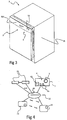
- Figure 3 shows a household appliance comprising a control panel 3 according to the present invention.
- the embodiment shown reveals a dishwasher comprising a control panel 3 according to the invention.
- control panel 3 The position of control panel 3 relative to household appliance 2 depends on the conformation of household appliance 2 itself.
- FIG. 4 schematically shows the electric interconnection between control panel 3 and household appliance 2.
- control unit 22 of household appliance 2 besides monitoring said sensors 24 and controlling actuators 23, is capable of communicating with said control panel 3.
- processing unit 65 adapted to process the data generated by control elements 4 of control panel 3, can be comprised in control panel 3 itself and/or in said control unit 22.
- the figure further reveals how the number of sensors and actuators can change based on the features of household appliance 2.
- Control panel 3 has a longer useful life, thanks to the fact that it comprises an electromagnetic selector 5 with the features described above. Indeed, selector 5 is free from sliding contacts, as sliding contacts are more likely to be subjected to faults due to wear.
- Panel 3 according to the invention increases the functions that can be implemented by a household appliance 2, with the same number of control elements 4.
- selector 5 allows you to implement both the rotation function and the pushbutton function.
- selector 5 allows you to increase the number of positions in its rotation, thus increasing the number of different functions that can be selected. Thanks to selector 5 according to the invention, there are no more electronic/mechanical limitations to the creation of the different positions of the selector, as the electronic functionality can be implemented tanks to a customizable computer program, without the mechanical restrictions present in the solution of the prior art.
- selector 5 also acts an an encoder, since it has a very high resolution.
- /EB NUMERICAL REFERENCES Household appliance 2 Outer casing 21
- Control unit 22 Actuators 23 Sensors 24
- Control panel 3 Support structure 31 First surface 31F Second surface 31B Housings 32
- Selector 5 Knob 50 Covering element 51 Shaft 52 Abutment elements 522 Magnet 53
- Elastic element 54 Body 55
- Processing unit 65 Axis "K"
Landscapes
- Engineering & Computer Science (AREA)
- Textile Engineering (AREA)
- Chemical & Material Sciences (AREA)
- Combustion & Propulsion (AREA)
- Mechanical Engineering (AREA)
- General Engineering & Computer Science (AREA)
- Switches With Compound Operations (AREA)
- Push-Button Switches (AREA)
- Cookers (AREA)
- Selective Calling Equipment (AREA)
- Vending Machines For Individual Products (AREA)
Applications Claiming Priority (1)
| Application Number | Priority Date | Filing Date | Title |
|---|---|---|---|
| IT102017000014858A IT201700014858A1 (it) | 2017-02-10 | 2017-02-10 | Pannello di controllo per dispositivi elettrodomestici e relativo dispositivo elettrodomestico. |
Publications (1)
| Publication Number | Publication Date |
|---|---|
| EP3360458A1 true EP3360458A1 (fr) | 2018-08-15 |
Family
ID=59297207
Family Applications (1)
| Application Number | Title | Priority Date | Filing Date |
|---|---|---|---|
| EP18155480.9A Withdrawn EP3360458A1 (fr) | 2017-02-10 | 2018-02-07 | Panneau de commande pour appareil électroménager et appareil électroménager comportant un panneau de commande |
Country Status (2)
| Country | Link |
|---|---|
| EP (1) | EP3360458A1 (fr) |
| IT (1) | IT201700014858A1 (fr) |
Citations (6)
| Publication number | Priority date | Publication date | Assignee | Title |
|---|---|---|---|---|
| EP0600780A1 (fr) * | 1992-12-04 | 1994-06-08 | Société SCHOLTES | Commutateur de commande pour appareil de cuisson domestique |
| EP0844325A2 (fr) * | 1996-11-22 | 1998-05-27 | Siemens Aktiengesellschaft | Dispositif d'actionnement et d'affichage |
| EP0867792A1 (fr) * | 1997-03-26 | 1998-09-30 | Siemens Aktiengesellschaft | Dispositif de commande avec sécurité contre une utilisation non desirée |
| DE10319132A1 (de) * | 2003-04-28 | 2004-11-18 | BSH Bosch und Siemens Hausgeräte GmbH | Drehwähler mit Druckfunktion |
| EP2149960A1 (fr) * | 2008-07-31 | 2010-02-03 | Electrolux Home Products Corporation N.V. | Appareil électrique à efficacité améliorée |
| EP2458287A1 (fr) * | 2010-11-30 | 2012-05-30 | Vestel Beyaz Esya Sanayi Ve Ticaret A.S. | Panneau de commande d'un appareil de cuisson |
-
2017
- 2017-02-10 IT IT102017000014858A patent/IT201700014858A1/it unknown
-
2018
- 2018-02-07 EP EP18155480.9A patent/EP3360458A1/fr not_active Withdrawn
Patent Citations (6)
| Publication number | Priority date | Publication date | Assignee | Title |
|---|---|---|---|---|
| EP0600780A1 (fr) * | 1992-12-04 | 1994-06-08 | Société SCHOLTES | Commutateur de commande pour appareil de cuisson domestique |
| EP0844325A2 (fr) * | 1996-11-22 | 1998-05-27 | Siemens Aktiengesellschaft | Dispositif d'actionnement et d'affichage |
| EP0867792A1 (fr) * | 1997-03-26 | 1998-09-30 | Siemens Aktiengesellschaft | Dispositif de commande avec sécurité contre une utilisation non desirée |
| DE10319132A1 (de) * | 2003-04-28 | 2004-11-18 | BSH Bosch und Siemens Hausgeräte GmbH | Drehwähler mit Druckfunktion |
| EP2149960A1 (fr) * | 2008-07-31 | 2010-02-03 | Electrolux Home Products Corporation N.V. | Appareil électrique à efficacité améliorée |
| EP2458287A1 (fr) * | 2010-11-30 | 2012-05-30 | Vestel Beyaz Esya Sanayi Ve Ticaret A.S. | Panneau de commande d'un appareil de cuisson |
Also Published As
| Publication number | Publication date |
|---|---|
| IT201700014858A1 (it) | 2018-08-10 |
Similar Documents
| Publication | Publication Date | Title |
|---|---|---|
| EP3232294B1 (fr) | Ensemble de codeur pour un bouton d'appareil ménager | |
| CN110832156B (zh) | 电磁门锁 | |
| CN101364496B (zh) | 旋转式选择器 | |
| US10466736B2 (en) | Self-centering spring return mechanism for an appliance knob | |
| US10113885B2 (en) | Method and rotational angle sensor for measuring an angular position of a rotatable signal-inducing unit | |
| US20180206309A1 (en) | Lighting Control Console Having A Tactile Sensor System | |
| US20190317544A1 (en) | Haptic knob, in particular for an electric or electronic apparatus, for example a household appliance | |
| WO2013159067A1 (fr) | Commutateurs à champ magnétique | |
| US7609138B2 (en) | Rotary selector | |
| US10423231B2 (en) | Miniature printed circuit board mounted haptic device | |
| EP3002562B1 (fr) | Codeur capacitif absolu | |
| JP6633678B2 (ja) | 位置指示用のキーパッド又は類似機構を使用する回転スイッチ | |
| JP2015026613A (ja) | 電気器具を切替え及び制御するための装置 | |
| KR101756744B1 (ko) | 전자식 조이스틱 장치 | |
| CN109690712B (zh) | 转换操作元件 | |
| CN111262569A (zh) | 触控开关及触控开关的操作方法 | |
| IT201700014858A1 (it) | Pannello di controllo per dispositivi elettrodomestici e relativo dispositivo elettrodomestico. | |
| CN223576784U (zh) | 一种旋钮组件 | |
| KR20070080071A (ko) | 세탁기 | |
| US12595611B2 (en) | Clothes treatment apparatus | |
| US12467187B2 (en) | Clothing treatment device | |
| WO2024076547A1 (fr) | Ensemble capteur à effet hall destiné à être utilisé avec des joysticks de manette de jeu | |
| KR20180023682A (ko) | 디스플레이가 내장된 전기밥솥의 조그 다이얼 구조체 | |
| CN111916293A (zh) | 用于对家用器具进行功能控制的操作设备 | |
| SE542315C2 (en) | Control knob |
Legal Events
| Date | Code | Title | Description |
|---|---|---|---|
| PUAI | Public reference made under article 153(3) epc to a published international application that has entered the european phase |
Free format text: ORIGINAL CODE: 0009012 |
|
| STAA | Information on the status of an ep patent application or granted ep patent |
Free format text: STATUS: THE APPLICATION HAS BEEN PUBLISHED |
|
| AK | Designated contracting states |
Kind code of ref document: A1 Designated state(s): AL AT BE BG CH CY CZ DE DK EE ES FI FR GB GR HR HU IE IS IT LI LT LU LV MC MK MT NL NO PL PT RO RS SE SI SK SM TR |
|
| AX | Request for extension of the european patent |
Extension state: BA ME |
|
| STAA | Information on the status of an ep patent application or granted ep patent |
Free format text: STATUS: THE APPLICATION IS DEEMED TO BE WITHDRAWN |
|
| 18D | Application deemed to be withdrawn |
Effective date: 20190216 |