EP3360595A1 - Respiratorisches ventil für ventilator - Google Patents
Respiratorisches ventil für ventilator Download PDFInfo
- Publication number
- EP3360595A1 EP3360595A1 EP16852977.4A EP16852977A EP3360595A1 EP 3360595 A1 EP3360595 A1 EP 3360595A1 EP 16852977 A EP16852977 A EP 16852977A EP 3360595 A1 EP3360595 A1 EP 3360595A1
- Authority
- EP
- European Patent Office
- Prior art keywords
- valve
- port
- inhaling
- respiratory
- cavity
- Prior art date
- Legal status (The legal status is an assumption and is not a legal conclusion. Google has not performed a legal analysis and makes no representation as to the accuracy of the status listed.)
- Granted
Links
Images


Classifications
-
- A—HUMAN NECESSITIES
- A61—MEDICAL OR VETERINARY SCIENCE; HYGIENE
- A61M—DEVICES FOR INTRODUCING MEDIA INTO, OR ONTO, THE BODY; DEVICES FOR TRANSDUCING BODY MEDIA OR FOR TAKING MEDIA FROM THE BODY; DEVICES FOR PRODUCING OR ENDING SLEEP OR STUPOR
- A61M16/00—Devices for influencing the respiratory system of patients by gas treatment, e.g. ventilators; Tracheal tubes
- A61M16/20—Valves specially adapted to medical respiratory devices
- A61M16/201—Controlled valves
- A61M16/206—Capsule valves, e.g. mushroom, membrane valves
-
- A—HUMAN NECESSITIES
- A61—MEDICAL OR VETERINARY SCIENCE; HYGIENE
- A61M—DEVICES FOR INTRODUCING MEDIA INTO, OR ONTO, THE BODY; DEVICES FOR TRANSDUCING BODY MEDIA OR FOR TAKING MEDIA FROM THE BODY; DEVICES FOR PRODUCING OR ENDING SLEEP OR STUPOR
- A61M16/00—Devices for influencing the respiratory system of patients by gas treatment, e.g. ventilators; Tracheal tubes
- A61M16/08—Bellows; Connecting tubes ; Water traps; Patient circuits
- A61M16/0816—Joints or connectors
-
- A—HUMAN NECESSITIES
- A61—MEDICAL OR VETERINARY SCIENCE; HYGIENE
- A61M—DEVICES FOR INTRODUCING MEDIA INTO, OR ONTO, THE BODY; DEVICES FOR TRANSDUCING BODY MEDIA OR FOR TAKING MEDIA FROM THE BODY; DEVICES FOR PRODUCING OR ENDING SLEEP OR STUPOR
- A61M16/00—Devices for influencing the respiratory system of patients by gas treatment, e.g. ventilators; Tracheal tubes
- A61M16/08—Bellows; Connecting tubes ; Water traps; Patient circuits
- A61M16/0816—Joints or connectors
- A61M16/0841—Joints or connectors for sampling
- A61M16/0858—Pressure sampling ports
-
- A—HUMAN NECESSITIES
- A61—MEDICAL OR VETERINARY SCIENCE; HYGIENE
- A61M—DEVICES FOR INTRODUCING MEDIA INTO, OR ONTO, THE BODY; DEVICES FOR TRANSDUCING BODY MEDIA OR FOR TAKING MEDIA FROM THE BODY; DEVICES FOR PRODUCING OR ENDING SLEEP OR STUPOR
- A61M16/00—Devices for influencing the respiratory system of patients by gas treatment, e.g. ventilators; Tracheal tubes
- A61M16/20—Valves specially adapted to medical respiratory devices
- A61M16/201—Controlled valves
- A61M16/202—Controlled valves electrically actuated
- A61M16/203—Proportional
- A61M16/205—Proportional used for exhalation control
-
- A—HUMAN NECESSITIES
- A61—MEDICAL OR VETERINARY SCIENCE; HYGIENE
- A61M—DEVICES FOR INTRODUCING MEDIA INTO, OR ONTO, THE BODY; DEVICES FOR TRANSDUCING BODY MEDIA OR FOR TAKING MEDIA FROM THE BODY; DEVICES FOR PRODUCING OR ENDING SLEEP OR STUPOR
- A61M16/00—Devices for influencing the respiratory system of patients by gas treatment, e.g. ventilators; Tracheal tubes
- A61M16/20—Valves specially adapted to medical respiratory devices
- A61M16/208—Non-controlled one-way valves, e.g. exhalation, check, pop-off non-rebreathing valves
Definitions
- the present invention relates to the technical field of ventilators, and in particular to a respiratory valve for a ventilator.
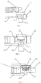
- a mechanical PEEP valve is externally connected at an exhalation port of a respiratory valve, a typical structure of which is as shown in Figs. 1 and 2 .
- the mechanical PEEP valve is mounted at a mechanical PEEP port 312 on a respiratory valve 3
- a valve cover 33 matched with the mechanical PEEP valve is mounted at the top of the respiratory valve 3 for the use of patients to expirate.
- an airflow with pressure provided by a built-in electronic PEEP valve of the ventilator host can be controlled using a software, to offer control gas with different pressures so as to maintain a respective PEEP value.
- a typical structure is as shown in Fig.
- existing respiratory valves may also be divided into two types, that is, a respiratory valve equipped with mechanical PEEP and a respiratory valve equipped with electronic PEEP.
- a respiratory valve equipped with mechanical PEEP As limited by their own structures, each type of respiratory valves is only applicable to the foregoing corresponding type of ventilators and cannot be used universally.
- a hospital or ventilator manufacturer is stocked with various types of ventilators which, further, are equipped with different respiratory valves, thereby causing confusion.
- it is adverse to efficient management and storage.
- An object of the present invention is to solve such a technical problem that an existing respiratory valve cannot be used universally for all ventilators due to its structural limitation.
- the present invention provides a respiratory valve for a ventilator, with which ventilators having different types of PEEP valves can be used universally.
- a respiratory valve for a ventilator comprises an inhaling pipeline port, a patient end port, a pressure sampling port and a valve port; and is characterized in that, the respiratory valve further comprises a dual purpose port; the inhaling pipeline port, the patient end port, the pressure sampling port, the valve port and the dual purpose port are in communication with each other through a first cavity provided at the center of the respiratory valve; the dual purpose port is connected to a mechanical PEEP valve, and the valve port is connected to a valve cover matched with the mechanical PEEP valve, or the dual purpose port is directly used as an exhalation port, and the valve port is connected to a valve cover matched with an electronic PEEP valve.
- a radial cross section of the inhaling pipeline port is covered with a first one-way membrane thereon, the first one-way membrane being mounted on a first support with an air vent which is provided at the end of the inhaling pipeline port, and used for preventing gas within the first cavity from flowing back into the inhaling pipeline port.
- a secure inhaling port is further comprised, one end of the secure inhaling port being in communication with the atmosphere, and the other end thereof being in communication with the first cavity.
- a radial cross section of the secure inhaling port is covered with a second one-way membrane thereon, the second one-way membrane being mounted on a second support with an air vent which is provided at the end of the secure inhaling port, and used for preventing gas within the first cavity from flowing back to the atmosphere through the secure inhaling port.
- an edge of the secure inhaling port at an end close to the atmosphere is provided with an anti-blocking notch.
- valve port faces upwards
- valve cover is fastened above the valve port and isolated from the first cavity by a respiratory membrane covering the valve port, whereby a second cavity is formed.
- the exhalation membrane moves along a vertical direction under the mutual action of air pressures at both sides
- an outer wall of the valve port is circumferentially provided with an annular air hole
- a bottom of the annular air hole is in communication with the dual purpose port
- gas within the first cavity flows through a gap formed between the exhalation membrane moving upward and the valve port, into the annular air hole, and flows out via the dual purpose port.
- a control gas channel is provided on a side wall of the inhaling pipeline port, a first annular slot is provided at the end of the control gas channel, a circular hole is provided at an edge of the exhalation membrane, and a lower surface of the circular hole is connected to the first annular slot.
- an inner surface of the valve cover matched with the mechanical PEEP valve is provided with a second annular slot and a gas-guiding slot, and an upper surface of the circular hole is connected to the second annular slot, so that gas of the inhaling pipeline port flows through the control gas channel, the first annular slot and the circular hole in sequence, to the second annular slot, and gas within the second annular slot is directed to the second cavity by the gas-guiding slot.
- valve cover matched with the electronic PEEP valve seals an upper surface of the circular hole, and a top of the valve cover matched with the electronic PEEP valve is provided with an electronic PEEP control port, via which the electronic PEEP valve is connected to the second cavity so that an air pressure within the second cavity is controlled at a set value of the electronic PEEP valve.
- an outer edge of the annular air hole is circumferentially unevenly distributed with three bosses, and the three bosses are matched with three arc notches provided at an inner surface of the valve cover matched with a respective PEEP valve.
- An outer surface of the valve cover is provided with a long slot at a position opposite to each arc notch, a protrusion being provided at the middle of one of the long slots for clamping the boss which rotates into the long slot.
- the respiratory valve of the present invention enables itself to be used with both a mechanical PEEP valve and an electronic PEEP valve by a dual purpose port provided.
- a valve cover matched with a various PEEP valve needs to be changed to realize a universal usage of different ventilators, thereby increasing an applicable scope and work efficiency of the respiratory valve.
- a respiratory valve for a ventilator comprises: an inhaling pipeline port, a patient end port, a pressure sampling port, a valve port and a dual purpose port.
- the dual purpose port is connected to a mechanical PEEP valve, and the valve port is connected to a valve cover matched with the mechanical PEEP valve, or the dual purpose port is directly used as an exhalation port, and the valve port is connected to a valve cover matched with an electronic PEEP valve.
- a respiratory valve based on the foregoing structure such as a respiratory valve equipped with a mechanical PEEP valve as shown in Figs. 5 and 6 specifically comprises: an inhaling pipeline port 315, a patient end port 2, a pressure sampling port 311, a valve port 319 and a dual purpose port 314.
- the inhaling pipeline port 315, the patient end port 2, the pressure sampling port 311, the valve port 319 and the dual purpose port 314 are in communication with each other through a first cavity 316 provided at the center of the respiratory valve.
- the dual purpose port 314 is connected to the mechanical PEP valve, and the valve port 319 is connected to a valve cover 33 matched with the mechanical PEEP valve.
- a radial cross section of the inhaling pipeline port 315 is covered with a first one-way membrane 34 thereon, and the first one-way membrane 34 is mounted on a first support 10 with an air vent which is provided at the end of the inhaling pipeline port 315, and is used for preventing gas within the first cavity 316 from flowing back into the inhaling pipeline port 315.
- the valve port 319 faces upwards, and the valve cover is fastened above the valve port 319 and isolated from the first cavity 316 by an exhalation membrane 35 covering the valve port 319, whereby a second cavity 36 is formed.
- the exhalation membrane 35 moves along a vertical direction under the mutual action of air pressures at both sides.
- an outer wall of the valve port 319 is circumferentially provided with an annular air hole 11, and a bottom of the annular air hole 11 is in communication with the dual purpose port 314. Gas within the first cavity 316 flows through a gap formed between the exhalation membrane 35 moving upward and the valve port 319, into the annular air hole 11, and flows out via the dual purpose port 314.
- a control gas channel 318 is provided on a side wall of the inhaling pipeline port 315, a first annular slot 317 is provided at the end of the control gas channel 318, an edge of the exhalation membrane 35 is provided with a circular hole 351, and a lower surface of the circular hole 351 is connected to the first annular slot 317.
- a second annular slot 331 and a gas-guiding slot 332 are provided on an inner surface of the valve cover 33 matched with the mechanical PEEP valve.
- An upper surface of the circular hole 351 is connected to the second annular slot 331 so that gas of the inhaling pipeline port 315 flows through the control gas channel 318, the first annular slot 317 and the circular hole 351 in sequence, to the second annular slot 331, and gas within the second annular slot 331 is directed to the second cavity 36 by the gas-guiding slot 332.
- the respiratory valve may further comprise a secure inhaling port 37, one end of the secure inhaling port 37 is in communication with the atmosphere, and the other end thereof is in communication with the first cavity 316.
- a radial cross section of the secure inhaling port 37 is covered with a second one-way membrane 38 thereon, and the second one-way membrane 38 is mounted on a second support 39 with an air vent which is provided at the end of the secure inhaling port 37, and used for preventing gas within the first cavity 316 from flowing back to the atmosphere through the secure inhaling port 37.
- An edge of the secure inhaling port 37 at an end close to the atmosphere is provided with an anti-blocking notch 371 for preventing the secure inhaling port 37 from being blocked by a quilt or clothing for negligence.
- the valve cover 33 matched with the mechanical PEEP valve is used with the valve body 31 as a complete set, and the mechanical PEEP valve is mounted on the dual purpose port 314.
- the inhaling pipeline port 315 is connected to an inhaling pipeline 1, and the pressure sampling port 311 is connected to a pressure sampling pipe 4.
- the ventilator When the ventilator inhales normally, the ventilator supplies a gas mixture of air and oxygen into the first cavity 316 via the inhaling pipeline port 315 and the first one-way membrane 34, wherein the first one-way membrane 34 is mounted on the first support 10 which is provided with an air vent at the end of the inhaling pipeline port 315.
- a portion of gas within the inhaling pipeline port 315 goes through the control gas channel 318 on the valve body 31, upward through a circular hole 351 on the exhalation membrane 35 and the second annular slot 331 on the valve cover 33 matched with the mechanical PEEP valve, and then through the gas-guiding slot 332 into the second cavity 36.
- a top of the control gas channel 318 is in communication with the first annular slot 317 at the top of the valve body 31.
- Such a design may avoid the risk that gas cannot pass through due to non-concentricity of the circular hole 351 of the exhalation membrane 35 and the control gas channel 318. That is, no matter how the exhalation membrane 35 is mounted, the gas mixture of air and oxygen may circulate to the circular hole 351 on the exhalation membrane 35 via the first annular slot 317.
- the second annular slot 331 provided on the valve cover 33 matched with the mechanical PEEP valve serves the same purpose as the first annular slot 317, i.e. avoiding the risk that the circular hole 315 cannot be connected to the gas-guiding slot 332 when the circular hole 315 deviates from a preset position.
- the exhalation membrane 35 is closely attached to the valve port 319 of the valve body 31 to effect a sealing function.
- the membrane at the secure inhaling port 37 is attached, under the pressure within the first cavity, to the second support 39 which is provided with an air vent at the end of the secure inhaling port 37 to affect a sealing function.
- a portion of the gas mixture of air and oxygen enters the pressure sampling port 311 to effect gas channel pressure sampling, and the rest of the gas mixture of air and oxygen enters a patient end port 2 to be supplied to a patient.
- An outer surface of the patient end port 2 is an outer conical structure 21 for connecting with a mask, and an inner surface thereof is an inner conical structure 22 for connecting with a tracheal cannula.
- a gas pressure within the second cavity 36 is also equal to the atmospheric pressure, thus the first one-way membrane 34 is attached, under the pressure of gas in the first cavity 316, to the first support 10 to effect a sealing function so as to prevent the gas exhaled by the patient from flowing back to and contaminating the ventilator via the inhaling pipeline port 315.
- the exhalation membrane 35 is driven to move upward, at which point a gap appears between the exhalation membrane 35 and the valve port 319. Gas within the first cavity 316 is discharged through this gap, into the dual purpose port 314, and then into the atmosphere via the mechanical PEEP valve.
- a valve cover 32 matched with the electronic PEEP valve is used with the valve body 31 as a complete set, and the dual purpose port 314 is not connected with any other device but is only used as an exhalation port. If a one-way gas check membrane is provided inside the ventilator host, optionally the first one-way membrane 34 shown in Fig. 5 may not be mounted.
- the respiratory valve in the present embodiment differs from the respiratory valve in Embodiment I in structure in that, the valve cover 32 matched with the electronic PEEP valve is no longer provided with an annular slot thereon but firmly presses an edge of an exhalation membrane 35 to seal the circular hole 351 on the exhalation membrane 35. Under this state of use, neither the control gas channel 318 on the valve body 31 nor the circular hole 351 on the exhalation membrane 35 takes effect.
- a top of the valve cover 32 matched with the electronic PEEP valve is provided with an electronic PEEP control port 321, via which the PEEP control gas pipeline 5 is connected to the second cavity 36 so that the gas pressure within the second cavity 36 is controlled at a set value of the electronic PEEP valve.
- the pressure on the upper surface of the exhalation membrane 35 comes from the gas pressure given at the electronic PEEP control port 321, and this gas pressure is controlled by the electronic PEEP valve within the ventilator host.
- the exhalation membrane 35 is closely attached to the valve port 319 of the valve body 31 under a force to effect a sealing function, and the gas mixture of air and oxygen enters the first cavity 316 via the inhaling pipeline port 315 and then flows into the patient end port 2 to be supplied to the patient.
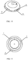
- the electronic PEEP control port 321 and the inhaling pipeline port 315 are generally rotated to the same direction, which requires the valve body 31 and the valve cover 32 matched with the electronic PEEP valve have a stopping function, so that after the valve cover 32 matched with the electronic PEEP valve rotates in place, the electronic PEEP control port 321 and the inhaling pipeline port 315 are fixed in the same direction. Therefore, with reference to Figs. 9 to 11 , a design is made in this embodiment as below:
- An outer edge of the annular air hole 11 at the top of the valve body 31 are circumferentially designed with three unevenly distributed and protruded bosses 6, while three arc notches 7 with the same shape are provided at respective positions at the bottom of the valve cover 32 matched with an electronic PEEP.
- the bosses 6 are matched with the three arc notches 7 provided at an inner surface of the valve cover 32 matched with the electronic PEEP valve.
- An outer surface of the valve cover 32 matched with the electronic PEEP valve is provided with a long slot 8 at a position opposite to each arc notch 7, whereby three long notches 8 are formed.
- the valve cover 32 matched with the electronic PEEP valve and the valve body 31 can only be mounted in a top-to-down direction due to intervention from other directions. Then, the valve cover is rotated. After the bosses 6 slide into the long slots 8, according to the designed dimension, when the bosses 6 reach the end of the long slots 8, the electronic PEEP control port 321 and the inhaling pipeline port 315 are exactly in the same direction.
- a plane where bases of any of the long slots 3 are located may be selected to be designed with a protrusion 9 used for clamping the boss 6 on the valve body to prevent the valve cover 32 matched with the electronic PEEP valve from rotating circumferentially and loosening.
- the valve cover matched with the mechanical PEEP may be provided thereon with respective arc notches, long slots and protrusions, so that the arc notches are fitted with the bosses and the valve cover matched with the mechanical PEEP is fixed to the valve port by the protrusions.
- the secure inhaling port may be provided with the arc-like anti-blocking notch 371.
- a supporting edge 372 without any notch plays a supporting role, so that the anti-blocking notch 371 remains in a suspended state all the time, ensuring that air can smoothly circulate into the respiratory valve.
Landscapes
- Health & Medical Sciences (AREA)
- Life Sciences & Earth Sciences (AREA)
- Public Health (AREA)
- Engineering & Computer Science (AREA)
- Anesthesiology (AREA)
- Biomedical Technology (AREA)
- Heart & Thoracic Surgery (AREA)
- Pulmonology (AREA)
- Animal Behavior & Ethology (AREA)
- Hematology (AREA)
- General Health & Medical Sciences (AREA)
- Emergency Medicine (AREA)
- Veterinary Medicine (AREA)
- Respiratory Apparatuses And Protective Means (AREA)
- Check Valves (AREA)
- External Artificial Organs (AREA)
Applications Claiming Priority (2)
| Application Number | Priority Date | Filing Date | Title |
|---|---|---|---|
| CN201510644880.0A CN106563199B (zh) | 2015-10-08 | 2015-10-08 | 一种用于呼吸机的呼吸阀 |
| PCT/CN2016/079345 WO2017059667A1 (zh) | 2015-10-08 | 2016-04-15 | 一种用于呼吸机的呼吸阀 |
Publications (3)
| Publication Number | Publication Date |
|---|---|
| EP3360595A1 true EP3360595A1 (de) | 2018-08-15 |
| EP3360595A4 EP3360595A4 (de) | 2018-09-05 |
| EP3360595B1 EP3360595B1 (de) | 2019-07-03 |
Family
ID=58487298
Family Applications (1)
| Application Number | Title | Priority Date | Filing Date |
|---|---|---|---|
| EP16852977.4A Active EP3360595B1 (de) | 2015-10-08 | 2016-04-15 | Respiratorisches ventil für ventilator |
Country Status (4)
| Country | Link |
|---|---|
| EP (1) | EP3360595B1 (de) |
| CN (1) | CN106563199B (de) |
| EA (1) | EA035572B1 (de) |
| WO (1) | WO2017059667A1 (de) |
Cited By (4)
| Publication number | Priority date | Publication date | Assignee | Title |
|---|---|---|---|---|
| CN109908449A (zh) * | 2019-04-22 | 2019-06-21 | 濡新(北京)科技发展有限公司 | 一种呼气阀 |
| WO2023280710A1 (de) * | 2021-07-06 | 2023-01-12 | Hamilton Medical Ag | Exspirationsventil-baugruppe und atemgas-leitungsbaugruppe mit einer solchen |
| CN116447363A (zh) * | 2023-05-12 | 2023-07-18 | 南京工业大学 | 一种阻火呼吸阀 |
| EP3956004B1 (de) * | 2019-04-15 | 2024-02-28 | imtmedical ag | Gasventil zur belüftung, schaltung für ein belüftungssystem und verfahren zur bestimmung eines abgebenden gasstroms |
Families Citing this family (14)
| Publication number | Priority date | Publication date | Assignee | Title |
|---|---|---|---|---|
| JP6622688B2 (ja) * | 2016-12-26 | 2019-12-18 | 本田技研工業株式会社 | 熱交換器 |
| DE102017010485A1 (de) * | 2017-04-27 | 2018-10-31 | Weinmann Emergency Medical Technology Gmbh + Co. Kg | Vorrichtung zur Beatmung mit Patientenventil |
| CN110404147B (zh) * | 2018-04-27 | 2024-12-31 | 瑞炯医疗器械(上海)有限公司 | 一种提高双气压呼吸机性能的呼吸阀及其呼吸装置 |
| US20210275763A1 (en) * | 2018-07-06 | 2021-09-09 | Löwenstein Medical Technology S.A. | Gas control device for a ventilator |
| CN109027361B (zh) * | 2018-08-27 | 2019-10-22 | 珠海格力电器股份有限公司 | 安装结构、下出水水箱及空气处理装置 |
| CN113195025B (zh) * | 2019-01-22 | 2023-02-28 | 深圳迈瑞生物医疗电子股份有限公司 | 通气配件及患者通气接口 |
| CN109758153B (zh) * | 2019-01-30 | 2024-04-02 | 上海长征医院 | 全鼻腔气压检测设备及其应用方法 |
| TWI681788B (zh) * | 2019-03-14 | 2020-01-11 | 許定洋 | 呼吸器 |
| WO2021211679A1 (en) * | 2020-04-15 | 2021-10-21 | Vortran Medical Technology 1, Inc. | Fixed and adjustable peep valves for ventilators |
| CN111905226B (zh) * | 2020-09-16 | 2025-04-22 | 合肥九研医药科技开发有限公司 | 一种提供湿化氧疗的呼吸维持系统 |
| CN113143534B (zh) * | 2021-05-25 | 2024-06-18 | 上海威泽健康科技有限公司 | 一种单向呼吸阀及具有单向呼吸阀的动物辅助给药呼吸器 |
| CN113294570A (zh) * | 2021-05-26 | 2021-08-24 | 辽宁石油化工大学 | 一种具有负压保护功能的阻火呼吸阀 |
| EP4429743B1 (de) | 2021-11-09 | 2025-07-30 | Löwenstein Medical Technology S.A. | Ausatemventil |
| CN114366978B (zh) * | 2022-01-25 | 2023-10-24 | 徐州医科大学 | 一种快速开启的呼气阀、用于急救的呼吸机 |
Family Cites Families (15)
| Publication number | Priority date | Publication date | Assignee | Title |
|---|---|---|---|---|
| US3933171A (en) * | 1974-04-09 | 1976-01-20 | Airco, Inc. | Anesthesia breathing circuit with positive end expiratory pressure valve |
| US4437461A (en) * | 1982-04-16 | 1984-03-20 | Greenberg Mitchell H | Valve respirator device |
| WO2000027455A1 (en) * | 1998-11-06 | 2000-05-18 | Salter Labs | Nebulizer mouthpiece and accessories |
| DE102008026321A1 (de) * | 2007-06-14 | 2008-12-18 | Weinmann Geräte für Medizin GmbH & Co. KG | Patientenventil |
| EP2106819A1 (de) * | 2008-03-31 | 2009-10-07 | Linde AG | Druckstützbelüftung mit passivem PEEP-Ventil |
| EP2153859B1 (de) * | 2008-08-13 | 2015-12-23 | Drägerwerk AG & Co. KGaA | Medizinisches Beatmungssystem |
| CN101745169B (zh) * | 2008-12-09 | 2013-10-23 | 北京谊安医疗系统股份有限公司 | 呼吸阀装置 |
| CN101766862B (zh) * | 2008-12-26 | 2013-03-06 | 北京谊安医疗系统股份有限公司 | 用于麻醉机的控制转换阀 |
| CN102114301B (zh) * | 2009-12-31 | 2014-04-02 | 北京谊安医疗系统股份有限公司 | Peep阀及具有该peep阀的呼吸机 |
| CN102274567A (zh) * | 2010-06-12 | 2011-12-14 | 史密斯医疗国际有限公司 | 呼吸管控制阀及用以连接该控制阀的气体管路 |
| US9504796B2 (en) * | 2011-10-14 | 2016-11-29 | The Trustees Of The Stevens Institute Of Technology | Reducing ventilator-induced lung injury |
| CN103182140B (zh) * | 2011-12-30 | 2016-06-22 | 北京谊安医疗系统股份有限公司 | 呼吸阀 |
| GB2505689B (en) * | 2012-09-07 | 2018-11-21 | Intersurgical Ag | Improvements to valve assemblies |
| CN203943996U (zh) * | 2014-07-03 | 2014-11-19 | 河南辉瑞生物医电技术有限公司 | 一种呼吸阀 |
| CN104784794B (zh) * | 2015-05-08 | 2017-03-29 | 濡新(北京)科技发展有限公司 | 一种咳痰管路 |
-
2015
- 2015-10-08 CN CN201510644880.0A patent/CN106563199B/zh active Active
-
2016
- 2016-04-15 WO PCT/CN2016/079345 patent/WO2017059667A1/zh not_active Ceased
- 2016-04-15 EP EP16852977.4A patent/EP3360595B1/de active Active
- 2016-04-15 EA EA201890863A patent/EA035572B1/ru not_active IP Right Cessation
Cited By (5)
| Publication number | Priority date | Publication date | Assignee | Title |
|---|---|---|---|---|
| EP3956004B1 (de) * | 2019-04-15 | 2024-02-28 | imtmedical ag | Gasventil zur belüftung, schaltung für ein belüftungssystem und verfahren zur bestimmung eines abgebenden gasstroms |
| US12246134B2 (en) | 2019-04-15 | 2025-03-11 | Imtmedical Ag | Gas valve for ventilation, a circuit for a ventilation system and a method for determining a releasing gas flow |
| CN109908449A (zh) * | 2019-04-22 | 2019-06-21 | 濡新(北京)科技发展有限公司 | 一种呼气阀 |
| WO2023280710A1 (de) * | 2021-07-06 | 2023-01-12 | Hamilton Medical Ag | Exspirationsventil-baugruppe und atemgas-leitungsbaugruppe mit einer solchen |
| CN116447363A (zh) * | 2023-05-12 | 2023-07-18 | 南京工业大学 | 一种阻火呼吸阀 |
Also Published As
| Publication number | Publication date |
|---|---|
| WO2017059667A1 (zh) | 2017-04-13 |
| EP3360595A4 (de) | 2018-09-05 |
| EP3360595B1 (de) | 2019-07-03 |
| CN106563199B (zh) | 2020-02-04 |
| CN106563199A (zh) | 2017-04-19 |
| EA201890863A1 (ru) | 2018-09-28 |
| EA035572B1 (ru) | 2020-07-09 |
Similar Documents
| Publication | Publication Date | Title |
|---|---|---|
| EP3360595A1 (de) | Respiratorisches ventil für ventilator | |
| US10272223B2 (en) | Respiratory valve apparatus | |
| CN102015000B (zh) | 排气组件 | |
| FI71060C (fi) | Anordning vid narkosmask | |
| US20210178109A1 (en) | Breathing assistance apparatus | |
| JP5049286B2 (ja) | 一体型緩衝体鼻枕を有する患者界面材 | |
| KR101118234B1 (ko) | 환기장치 | |
| CA2915244C (en) | Helmet for anesthesia | |
| US8887729B2 (en) | Tracheostomy tube assemblies having spherical bearing elements | |
| US9616194B2 (en) | Ventilation mask with integrated piloted exhalation valve and method of ventilating a patient using the same | |
| US20150034079A1 (en) | Ventilation Mask with Integrated Piloted Exhalation Valve | |
| EP2421590B1 (de) | System und verfahren für schaltungen zur cpap-freigabe zwecks nulldruck-erzeugung | |
| US10682482B2 (en) | Fresh air and anti-asphyxiation assembly | |
| US20170246414A1 (en) | Breathing mask with nasal cannula | |
| JP2015516258A (ja) | 患者インタフェース装置 | |
| ES2972468T3 (es) | Dispositivo de ventilación con presión continua adecuado para tratar a pacientes con insuficiencia respiratoria | |
| CN204106793U (zh) | 一种风箱单向阀及麻醉机 | |
| US20220047838A1 (en) | One-Way CPAP/BiPAP Mask | |
| CN109908449A (zh) | 一种呼气阀 | |
| US20210290888A1 (en) | Inspiratory resistor valve system with expiratory port | |
| CN103768734A (zh) | 用于呼吸面具的角形件 | |
| CN209204387U (zh) | 一种辅助发声阀 | |
| CN106943656A (zh) | 无创呼吸面罩及其所应用的呼吸机 | |
| CN203694324U (zh) | 一种用于口腔治疗的鼻罩 | |
| JP2006006984A (ja) | 人工呼吸装置および人工呼吸装置用空気ポンプ |
Legal Events
| Date | Code | Title | Description |
|---|---|---|---|
| STAA | Information on the status of an ep patent application or granted ep patent |
Free format text: STATUS: THE INTERNATIONAL PUBLICATION HAS BEEN MADE |
|
| PUAI | Public reference made under article 153(3) epc to a published international application that has entered the european phase |
Free format text: ORIGINAL CODE: 0009012 |
|
| STAA | Information on the status of an ep patent application or granted ep patent |
Free format text: STATUS: REQUEST FOR EXAMINATION WAS MADE |
|
| 17P | Request for examination filed |
Effective date: 20180502 |
|
| AK | Designated contracting states |
Kind code of ref document: A1 Designated state(s): AL AT BE BG CH CY CZ DE DK EE ES FI FR GB GR HR HU IE IS IT LI LT LU LV MC MK MT NL NO PL PT RO RS SE SI SK SM TR |
|
| AX | Request for extension of the european patent |
Extension state: BA ME |
|
| A4 | Supplementary search report drawn up and despatched |
Effective date: 20180802 |
|
| RIC1 | Information provided on ipc code assigned before grant |
Ipc: A61M 16/08 20060101ALI20180727BHEP Ipc: A61M 16/20 20060101AFI20180727BHEP |
|
| DAV | Request for validation of the european patent (deleted) | ||
| DAX | Request for extension of the european patent (deleted) | ||
| GRAP | Despatch of communication of intention to grant a patent |
Free format text: ORIGINAL CODE: EPIDOSNIGR1 |
|
| STAA | Information on the status of an ep patent application or granted ep patent |
Free format text: STATUS: GRANT OF PATENT IS INTENDED |
|
| INTG | Intention to grant announced |
Effective date: 20190124 |
|
| GRAS | Grant fee paid |
Free format text: ORIGINAL CODE: EPIDOSNIGR3 |
|
| GRAA | (expected) grant |
Free format text: ORIGINAL CODE: 0009210 |
|
| STAA | Information on the status of an ep patent application or granted ep patent |
Free format text: STATUS: THE PATENT HAS BEEN GRANTED |
|
| AK | Designated contracting states |
Kind code of ref document: B1 Designated state(s): AL AT BE BG CH CY CZ DE DK EE ES FI FR GB GR HR HU IE IS IT LI LT LU LV MC MK MT NL NO PL PT RO RS SE SI SK SM TR |
|
| REG | Reference to a national code |
Ref country code: GB Ref legal event code: FG4D |
|
| REG | Reference to a national code |
Ref country code: CH Ref legal event code: EP Ref country code: AT Ref legal event code: REF Ref document number: 1150241 Country of ref document: AT Kind code of ref document: T Effective date: 20190715 |
|
| REG | Reference to a national code |
Ref country code: IE Ref legal event code: FG4D |
|
| REG | Reference to a national code |
Ref country code: DE Ref legal event code: R096 Ref document number: 602016016484 Country of ref document: DE |
|
| REG | Reference to a national code |
Ref country code: NL Ref legal event code: MP Effective date: 20190703 |
|
| REG | Reference to a national code |
Ref country code: LT Ref legal event code: MG4D |
|
| REG | Reference to a national code |
Ref country code: AT Ref legal event code: MK05 Ref document number: 1150241 Country of ref document: AT Kind code of ref document: T Effective date: 20190703 |
|
| PG25 | Lapsed in a contracting state [announced via postgrant information from national office to epo] |
Ref country code: LT Free format text: LAPSE BECAUSE OF FAILURE TO SUBMIT A TRANSLATION OF THE DESCRIPTION OR TO PAY THE FEE WITHIN THE PRESCRIBED TIME-LIMIT Effective date: 20190703 Ref country code: HR Free format text: LAPSE BECAUSE OF FAILURE TO SUBMIT A TRANSLATION OF THE DESCRIPTION OR TO PAY THE FEE WITHIN THE PRESCRIBED TIME-LIMIT Effective date: 20190703 Ref country code: AT Free format text: LAPSE BECAUSE OF FAILURE TO SUBMIT A TRANSLATION OF THE DESCRIPTION OR TO PAY THE FEE WITHIN THE PRESCRIBED TIME-LIMIT Effective date: 20190703 Ref country code: SE Free format text: LAPSE BECAUSE OF FAILURE TO SUBMIT A TRANSLATION OF THE DESCRIPTION OR TO PAY THE FEE WITHIN THE PRESCRIBED TIME-LIMIT Effective date: 20190703 Ref country code: FI Free format text: LAPSE BECAUSE OF FAILURE TO SUBMIT A TRANSLATION OF THE DESCRIPTION OR TO PAY THE FEE WITHIN THE PRESCRIBED TIME-LIMIT Effective date: 20190703 Ref country code: NO Free format text: LAPSE BECAUSE OF FAILURE TO SUBMIT A TRANSLATION OF THE DESCRIPTION OR TO PAY THE FEE WITHIN THE PRESCRIBED TIME-LIMIT Effective date: 20191003 Ref country code: CZ Free format text: LAPSE BECAUSE OF FAILURE TO SUBMIT A TRANSLATION OF THE DESCRIPTION OR TO PAY THE FEE WITHIN THE PRESCRIBED TIME-LIMIT Effective date: 20190703 Ref country code: PT Free format text: LAPSE BECAUSE OF FAILURE TO SUBMIT A TRANSLATION OF THE DESCRIPTION OR TO PAY THE FEE WITHIN THE PRESCRIBED TIME-LIMIT Effective date: 20191104 Ref country code: NL Free format text: LAPSE BECAUSE OF FAILURE TO SUBMIT A TRANSLATION OF THE DESCRIPTION OR TO PAY THE FEE WITHIN THE PRESCRIBED TIME-LIMIT Effective date: 20190703 Ref country code: BG Free format text: LAPSE BECAUSE OF FAILURE TO SUBMIT A TRANSLATION OF THE DESCRIPTION OR TO PAY THE FEE WITHIN THE PRESCRIBED TIME-LIMIT Effective date: 20191003 |
|
| PG25 | Lapsed in a contracting state [announced via postgrant information from national office to epo] |
Ref country code: RS Free format text: LAPSE BECAUSE OF FAILURE TO SUBMIT A TRANSLATION OF THE DESCRIPTION OR TO PAY THE FEE WITHIN THE PRESCRIBED TIME-LIMIT Effective date: 20190703 Ref country code: LV Free format text: LAPSE BECAUSE OF FAILURE TO SUBMIT A TRANSLATION OF THE DESCRIPTION OR TO PAY THE FEE WITHIN THE PRESCRIBED TIME-LIMIT Effective date: 20190703 Ref country code: AL Free format text: LAPSE BECAUSE OF FAILURE TO SUBMIT A TRANSLATION OF THE DESCRIPTION OR TO PAY THE FEE WITHIN THE PRESCRIBED TIME-LIMIT Effective date: 20190703 Ref country code: ES Free format text: LAPSE BECAUSE OF FAILURE TO SUBMIT A TRANSLATION OF THE DESCRIPTION OR TO PAY THE FEE WITHIN THE PRESCRIBED TIME-LIMIT Effective date: 20190703 Ref country code: GR Free format text: LAPSE BECAUSE OF FAILURE TO SUBMIT A TRANSLATION OF THE DESCRIPTION OR TO PAY THE FEE WITHIN THE PRESCRIBED TIME-LIMIT Effective date: 20191004 Ref country code: IS Free format text: LAPSE BECAUSE OF FAILURE TO SUBMIT A TRANSLATION OF THE DESCRIPTION OR TO PAY THE FEE WITHIN THE PRESCRIBED TIME-LIMIT Effective date: 20191103 |
|
| PG25 | Lapsed in a contracting state [announced via postgrant information from national office to epo] |
Ref country code: TR Free format text: LAPSE BECAUSE OF FAILURE TO SUBMIT A TRANSLATION OF THE DESCRIPTION OR TO PAY THE FEE WITHIN THE PRESCRIBED TIME-LIMIT Effective date: 20190703 |
|
| PG25 | Lapsed in a contracting state [announced via postgrant information from national office to epo] |
Ref country code: DK Free format text: LAPSE BECAUSE OF FAILURE TO SUBMIT A TRANSLATION OF THE DESCRIPTION OR TO PAY THE FEE WITHIN THE PRESCRIBED TIME-LIMIT Effective date: 20190703 Ref country code: PL Free format text: LAPSE BECAUSE OF FAILURE TO SUBMIT A TRANSLATION OF THE DESCRIPTION OR TO PAY THE FEE WITHIN THE PRESCRIBED TIME-LIMIT Effective date: 20190703 Ref country code: RO Free format text: LAPSE BECAUSE OF FAILURE TO SUBMIT A TRANSLATION OF THE DESCRIPTION OR TO PAY THE FEE WITHIN THE PRESCRIBED TIME-LIMIT Effective date: 20190703 Ref country code: EE Free format text: LAPSE BECAUSE OF FAILURE TO SUBMIT A TRANSLATION OF THE DESCRIPTION OR TO PAY THE FEE WITHIN THE PRESCRIBED TIME-LIMIT Effective date: 20190703 Ref country code: IT Free format text: LAPSE BECAUSE OF FAILURE TO SUBMIT A TRANSLATION OF THE DESCRIPTION OR TO PAY THE FEE WITHIN THE PRESCRIBED TIME-LIMIT Effective date: 20190703 |
|
| PG25 | Lapsed in a contracting state [announced via postgrant information from national office to epo] |
Ref country code: SM Free format text: LAPSE BECAUSE OF FAILURE TO SUBMIT A TRANSLATION OF THE DESCRIPTION OR TO PAY THE FEE WITHIN THE PRESCRIBED TIME-LIMIT Effective date: 20190703 Ref country code: IS Free format text: LAPSE BECAUSE OF FAILURE TO SUBMIT A TRANSLATION OF THE DESCRIPTION OR TO PAY THE FEE WITHIN THE PRESCRIBED TIME-LIMIT Effective date: 20200224 Ref country code: SK Free format text: LAPSE BECAUSE OF FAILURE TO SUBMIT A TRANSLATION OF THE DESCRIPTION OR TO PAY THE FEE WITHIN THE PRESCRIBED TIME-LIMIT Effective date: 20190703 |
|
| REG | Reference to a national code |
Ref country code: DE Ref legal event code: R097 Ref document number: 602016016484 Country of ref document: DE |
|
| PLBE | No opposition filed within time limit |
Free format text: ORIGINAL CODE: 0009261 |
|
| STAA | Information on the status of an ep patent application or granted ep patent |
Free format text: STATUS: NO OPPOSITION FILED WITHIN TIME LIMIT |
|
| PG2D | Information on lapse in contracting state deleted |
Ref country code: IS |
|
| 26N | No opposition filed |
Effective date: 20200603 |
|
| PG25 | Lapsed in a contracting state [announced via postgrant information from national office to epo] |
Ref country code: SI Free format text: LAPSE BECAUSE OF FAILURE TO SUBMIT A TRANSLATION OF THE DESCRIPTION OR TO PAY THE FEE WITHIN THE PRESCRIBED TIME-LIMIT Effective date: 20190703 |
|
| PG25 | Lapsed in a contracting state [announced via postgrant information from national office to epo] |
Ref country code: MC Free format text: LAPSE BECAUSE OF FAILURE TO SUBMIT A TRANSLATION OF THE DESCRIPTION OR TO PAY THE FEE WITHIN THE PRESCRIBED TIME-LIMIT Effective date: 20190703 |
|
| REG | Reference to a national code |
Ref country code: CH Ref legal event code: PL |
|
| PG25 | Lapsed in a contracting state [announced via postgrant information from national office to epo] |
Ref country code: LU Free format text: LAPSE BECAUSE OF NON-PAYMENT OF DUE FEES Effective date: 20200415 Ref country code: LI Free format text: LAPSE BECAUSE OF NON-PAYMENT OF DUE FEES Effective date: 20200430 Ref country code: CH Free format text: LAPSE BECAUSE OF NON-PAYMENT OF DUE FEES Effective date: 20200430 |
|
| REG | Reference to a national code |
Ref country code: BE Ref legal event code: MM Effective date: 20200430 |
|
| PG25 | Lapsed in a contracting state [announced via postgrant information from national office to epo] |
Ref country code: BE Free format text: LAPSE BECAUSE OF NON-PAYMENT OF DUE FEES Effective date: 20200430 |
|
| GBPC | Gb: european patent ceased through non-payment of renewal fee |
Effective date: 20200415 |
|
| PG25 | Lapsed in a contracting state [announced via postgrant information from national office to epo] |
Ref country code: IE Free format text: LAPSE BECAUSE OF NON-PAYMENT OF DUE FEES Effective date: 20200415 Ref country code: GB Free format text: LAPSE BECAUSE OF NON-PAYMENT OF DUE FEES Effective date: 20200415 |
|
| PG25 | Lapsed in a contracting state [announced via postgrant information from national office to epo] |
Ref country code: MT Free format text: LAPSE BECAUSE OF FAILURE TO SUBMIT A TRANSLATION OF THE DESCRIPTION OR TO PAY THE FEE WITHIN THE PRESCRIBED TIME-LIMIT Effective date: 20190703 Ref country code: CY Free format text: LAPSE BECAUSE OF FAILURE TO SUBMIT A TRANSLATION OF THE DESCRIPTION OR TO PAY THE FEE WITHIN THE PRESCRIBED TIME-LIMIT Effective date: 20190703 |
|
| PG25 | Lapsed in a contracting state [announced via postgrant information from national office to epo] |
Ref country code: MK Free format text: LAPSE BECAUSE OF FAILURE TO SUBMIT A TRANSLATION OF THE DESCRIPTION OR TO PAY THE FEE WITHIN THE PRESCRIBED TIME-LIMIT Effective date: 20190703 |
|
| P01 | Opt-out of the competence of the unified patent court (upc) registered |
Effective date: 20230529 |
|
| PGFP | Annual fee paid to national office [announced via postgrant information from national office to epo] |
Ref country code: DE Payment date: 20250411 Year of fee payment: 10 |
|
| PGFP | Annual fee paid to national office [announced via postgrant information from national office to epo] |
Ref country code: FR Payment date: 20250429 Year of fee payment: 10 |