EP3360609A1 - Filterelementanordnung mit einem zumindest verdoppelten sicherheitsfilterelement - Google Patents
Filterelementanordnung mit einem zumindest verdoppelten sicherheitsfilterelement Download PDFInfo
- Publication number
- EP3360609A1 EP3360609A1 EP17155628.5A EP17155628A EP3360609A1 EP 3360609 A1 EP3360609 A1 EP 3360609A1 EP 17155628 A EP17155628 A EP 17155628A EP 3360609 A1 EP3360609 A1 EP 3360609A1
- Authority
- EP
- European Patent Office
- Prior art keywords
- filter element
- filter
- medium
- safety
- main
- Prior art date
- Legal status (The legal status is an assumption and is not a legal conclusion. Google has not performed a legal analysis and makes no representation as to the accuracy of the status listed.)
- Withdrawn
Links
- 238000001914 filtration Methods 0.000 claims abstract description 11
- 238000000034 method Methods 0.000 claims abstract description 6
- 125000006850 spacer group Chemical group 0.000 claims description 9
- 239000000463 material Substances 0.000 description 16
- 229920002678 cellulose Polymers 0.000 description 3
- 239000001913 cellulose Substances 0.000 description 3
- 239000000835 fiber Substances 0.000 description 2
- 238000003466 welding Methods 0.000 description 2
- 238000004026 adhesive bonding Methods 0.000 description 1
- 230000001413 cellular effect Effects 0.000 description 1
- 238000004140 cleaning Methods 0.000 description 1
- 239000011362 coarse particle Substances 0.000 description 1
- 238000010276 construction Methods 0.000 description 1
- 238000011109 contamination Methods 0.000 description 1
- 239000000428 dust Substances 0.000 description 1
- 230000000694 effects Effects 0.000 description 1
- 239000010419 fine particle Substances 0.000 description 1
- 239000002245 particle Substances 0.000 description 1
Images


Classifications
-
- B—PERFORMING OPERATIONS; TRANSPORTING
- B01—PHYSICAL OR CHEMICAL PROCESSES OR APPARATUS IN GENERAL
- B01D—SEPARATION
- B01D46/00—Filters or filtering processes specially modified for separating dispersed particles from gases or vapours
- B01D46/24—Particle separators, e.g. dust precipitators, using rigid hollow filter bodies
- B01D46/2403—Particle separators, e.g. dust precipitators, using rigid hollow filter bodies characterised by the physical shape or structure of the filtering element
- B01D46/2411—Filter cartridges
-
- B—PERFORMING OPERATIONS; TRANSPORTING
- B01—PHYSICAL OR CHEMICAL PROCESSES OR APPARATUS IN GENERAL
- B01D—SEPARATION
- B01D46/00—Filters or filtering processes specially modified for separating dispersed particles from gases or vapours
- B01D46/42—Auxiliary equipment or operation thereof
- B01D46/4227—Manipulating filters or filter elements, e.g. handles or extracting tools
-
- B—PERFORMING OPERATIONS; TRANSPORTING
- B01—PHYSICAL OR CHEMICAL PROCESSES OR APPARATUS IN GENERAL
- B01D—SEPARATION
- B01D46/00—Filters or filtering processes specially modified for separating dispersed particles from gases or vapours
- B01D46/56—Filters or filtering processes specially modified for separating dispersed particles from gases or vapours with multiple filtering elements, characterised by their mutual disposition
- B01D46/58—Filters or filtering processes specially modified for separating dispersed particles from gases or vapours with multiple filtering elements, characterised by their mutual disposition connected in parallel
- B01D46/60—Filters or filtering processes specially modified for separating dispersed particles from gases or vapours with multiple filtering elements, characterised by their mutual disposition connected in parallel arranged concentrically or coaxially
-
- B—PERFORMING OPERATIONS; TRANSPORTING
- B01—PHYSICAL OR CHEMICAL PROCESSES OR APPARATUS IN GENERAL
- B01D—SEPARATION
- B01D46/00—Filters or filtering processes specially modified for separating dispersed particles from gases or vapours
- B01D46/56—Filters or filtering processes specially modified for separating dispersed particles from gases or vapours with multiple filtering elements, characterised by their mutual disposition
- B01D46/62—Filters or filtering processes specially modified for separating dispersed particles from gases or vapours with multiple filtering elements, characterised by their mutual disposition connected in series
- B01D46/64—Filters or filtering processes specially modified for separating dispersed particles from gases or vapours with multiple filtering elements, characterised by their mutual disposition connected in series arranged concentrically or coaxially
Definitions
- the present invention relates to a filter element arrangement for a filter, in particular for a gas filter, preferably for an air filter.
- the invention further relates to a filter, in particular a gas filter, preferably an air filter, comprising such a filter element arrangement.
- the invention also relates to a method for filtering a medium by using an aforesaid filter arrangement.
- US 2011/0192126 A1 , FR 2 967 917 A1 , GB 2 089 237 A and US 5,152,890 A each describe a filter with a main filter element, wherein the main filter element comprises several filter elements.
- the filter elements of the main filters described above are connected together non-detachably.
- the safety filter element preferably has a smaller pressure drop than the main filter element, so that most of the dirt in the medium to be filtered is separated in the main filter element, i.e. the main filtering action preferably occurs at the main filter element.
- the safety filter element serves the purpose of a "fail-safe" filter element: If the main filter element is clogged, the safety filter element will prevent the recipient of the medium from receiving either an insufficient amount of medium or from receiving dirty medium. The safety filter element further protects the recipient of the medium from receiving dirty medium in cases in which the main filter element is temporarily removed from the filter.
- the safety filter element is therefore detachably connected with the main filter element.
- the known safety filter elements have the disadvantage that the safety filter elements provide a poor performance.
- Another object of the present invention is the provision of a method for filtering a medium by using the aforementioned filter element arrangement.
- a filter element arrangement which comprises a main filter element and a safety filter element.
- the safety filter element is connected to the main filter element in a detachable way.
- the safety filter element comprises a first filter element and a second filter element.
- the second filter element is installed at least partially inside the first filter element.
- the filter element arrangement is installable in a filter housing of a filter.
- a bigger filtering area can be obtained in the available space by using several filter elements which are arranged one inside the other.
- different materials can be disposed in the various filter elements, for example non-woven and cellular materials.
- Non-woven or fleece materials offer higher resistance to the air flow in comparison with cellulose materials, for example when pleated filter elements like bellows are used.
- the cost of cellulose materials is higher than for non-woven materials.
- the advantages of both materials can be combined, for example by using cellulose material for the second filter element and fleece material for the first filter element. If the same material is used for both filter elements, the pressure drop will be reduced by the increased total filtering area of the safety filter element as compared with a filter without the second filter element.
- the pressure drop will be about the same as when a safety filter element consisting of only the first filter element with a material having less filtering quality is used, i.e. a more coarse material.
- the safety filter element is built in such a manner that the medium is passed either through the first filter element or the second filter element.
- a fluidical connection for example a channel, from the main filter to the second filter element can have the effect of guiding the medium partially to the second filter element.
- a connection allows for the control of the amount of the medium that will be filtered by the second filter element.
- the main filter element, the first filter element and the second filter element are built as circular filter elements sharing a common longitudinal filter element axis.
- the medium for example a gas like air
- the path of the medium flow is comparatively short with an optimal usage of the filter area.
- the first filter element is built to filter the medium radially inwards whereas the second filter element is built to filter the medium radially outwards.
- the first filter element can be placed with its radial wall facing the inner wall of the main filter, wherein the outlet is positioned at the axial end of the first filter element.
- the medium flows from the main filter element, which is positioned outside the first filter element, through the wall of the first filter element into its interior while being filtered.
- a direct fluidical connection for the medium can be built between the main filter and the interior of the second filter element. After entering the second filter element through this fluidical connection, the medium flows from the interior of the second filter element outwards through its radial wall while being filtered.
- the medium from the second filter element can exit the filter element arrangement through the same outlet as the medium from the first filter element. This allows for a compact construction of the filter.
- the first filter element is built to receive the medium in a radial direction from the main filter, and the second filter element has its inlet in an axial direction.
- the safety filter element is built to be removable from the main filter element in a nondestructive manner, in particular without tools.
- the filter element arrangement can then be deconstructed easily, for example for cleaning purposes.
- the safety filter element comprises a spacer which supports the safety filter element in an axial direction with respect to the bottom of the filter housing.
- the spacer comprises at least one radial feedthrough for providing the second filter element with medium from the main filter element.
- the medium can be guided from the lateral surface at the lower portion of the main filter element into the second filter element in an easy manner.
- the spacer is built as a handle for the removal of the safety filter element from the filter element arrangement.
- the filter safety element can be removed from the filter manually in an easy way.
- the filter comprises a filter housing and one of the aforesaid filter element arrangements, wherein the filter element arrangement is installed inside the filter housing.
- the filter housing can be helpful in better protecting the filter elements.
- the medium flows through an inlet to a main filter element and then through a wall of said main filter element into its interior. Afterwards a first portion of the medium is guided through a wall of a first filter element into the interior of the first filter element. A second portion of the medium is guided through a fluidical connection into the interior of a second filter element, which is positioned at least partially inside the first filter element. This second portion of the medium is guided through a wall of the second filter element into the interior of the first filter element. Then the second portion of the medium flows to an outlet together with the first portion of the medium.
- FIG. 1 shows a filter 110 with a filter housing 112 in which a filter element arrangement 114 is installed.
- the filter element arrangement 114 comprises a main filter element 116 and a safety filter element 118 .
- the safety filter element 118 comprises a first filter element 120 and a second filter element 122 .
- the first filter element 120 is disposed within the main filter element 116.
- the second filter element 122 is placed within the first filter element 120.
- the main filter element 116, the first filter element 120 and the second filter element 122 are built as concentric hollow cylinders. Both the first filter element 120 and the second filter element 122 comprise a radial mesh for the support of a filter fleece.
- a fluidical connection 130 is built next to the inner walls of the main filter element 116.
- the fluidical connection 130 is connected only to the lower end of the second filter element 122, not to the first filter element 120. Therefore the medium to be filtered, here air, is partially guided through the main filter element 116 into the interior of the second filter element 122.
- an outlet 132 is arranged at the top end of the safety filter element 118, which is disposed opposite to the fluidical connection 130. This outlet 132 is positioned at the area at the top of the first filter element 120.
- the outlet 132 is built in the form of a hollow cylinder of the same diameter as the first filter element 120.
- An inlet 134 for the medium is arranged at an outer radial wall of the filter housing 112.
- a floor element 136 is disposed, which is made of a material that is impermeable for the medium. Furthermore, at the top end of the main filter element 116 a material 138 is arranged that is impermeable for the medium.
- a fastening element 140 for example a snap fit, is disposed at the filter housing 112 for opening and closing the filter housing 112.
- the fastening element 140 can be opened in order to remove the filter element arrangement 114 from the filter 110, in particular the safety filter element 118.
- a valve 142 in particular a dust dump valve, is arranged opposite to the fastening element 140 at the bottom of the filter. Through this valve 142, contamination particles can leave the filter 110 after being filtered from the medium.
- the flow 144 of the medium from the inlet 134 to the main filter element 116 and afterwards through the first filter element 120 and/or the second filter element 122 to the outlet 132 is represented by thick black arrows in the figure.
- the second filter element 122 can be fixed to the first filter element 120 by spin welding or hot plate welding or by using a snap fit or gluing. Then the safety filter element 118 can be attached to the main filter element 116.
- Figure 2 shows the safety filter element 118 according to a first embodiment.
- the first filter element 120 may have a coarse fiber layer.
- the first filter element 120 is built to filter coarse particles.
- the second filter element 122 may either have a fine fiber layer in order to filter fine particles or a coarse filter layer, too.
- Figures 3 and 4 respectively show a longitudinal cross section through the first filter element 120 and the second filter element 122 in greater detail.
- Figure 5 shows a longitudinal cross section through the safety filter element 118 according to a second embodiment of the invention.
- a spacer 510 which is preferably built as a hook is disposed at the lower end of the second filter element 122.
- the spacer 510 has two functions. On the one hand it can be used as a handle to remove the safety filter element 118. On the other hand it serves as a spacer element, keeping the safety filter element 118 and the floor element 136 (not shown) or the filter housing 112 (not shown) at a distance, thereby ensuring that the fluidical connection 130 (not shown) stays open and portions of the medium can flow from the main filter element 116 into the second filter element 122.
- Figure 6 shows a longitudinal cross section of the safety filter element 118 according to a third embodiment of the invention.
- the second filter element 122 is built in the form of a hollow frustum of a cone.
- a second upper section 612 is built in which the second filter element 122 is built in the form of a dome 614 showing the cross section of a flat pointed lancet arch.
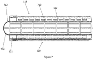
- Figure 7 shows a longitudinal cross section of the safety filter element 118 according to a fourth embodiment of the invention.
- the second filter element 122 is built in the form of a hollow cylinder along the full length of the first filter element 120.
- a second upper section 712 is built in which the second filter element 122 is built in the form of a hemispherical dome 714 .
- an outlet 132 for the filtered medium is built at the outer wall of the second filter element 122 below the dome 714.
- the medium While operating the filter element arrangement 114 according to the invention, the medium is guided through the inlet 134 and a wall of the main filter element 116 radially in a direction from the outside to the inside. Thereafter, a first portion of the medium is guided through a wall of the first filter element 120 in a direction from the outside to the inside. A second portion of the medium enters the fluidical connection 130 and is guided into the interior of the second filter element 122. Thereafter, this second portion of the medium flows through a wall of the second filter element 122 radially from the inside to the outside. Then both portions of the medium are guided together to the outlet 132, which is preferably built at the first filter element 120.
Landscapes
- Chemical & Material Sciences (AREA)
- Chemical Kinetics & Catalysis (AREA)
- Physics & Mathematics (AREA)
- Geometry (AREA)
- Filtering Of Dispersed Particles In Gases (AREA)
Priority Applications (1)
| Application Number | Priority Date | Filing Date | Title |
|---|---|---|---|
| EP17155628.5A EP3360609A1 (de) | 2017-02-10 | 2017-02-10 | Filterelementanordnung mit einem zumindest verdoppelten sicherheitsfilterelement |
Applications Claiming Priority (1)
| Application Number | Priority Date | Filing Date | Title |
|---|---|---|---|
| EP17155628.5A EP3360609A1 (de) | 2017-02-10 | 2017-02-10 | Filterelementanordnung mit einem zumindest verdoppelten sicherheitsfilterelement |
Publications (1)
| Publication Number | Publication Date |
|---|---|
| EP3360609A1 true EP3360609A1 (de) | 2018-08-15 |
Family
ID=58046509
Family Applications (1)
| Application Number | Title | Priority Date | Filing Date |
|---|---|---|---|
| EP17155628.5A Withdrawn EP3360609A1 (de) | 2017-02-10 | 2017-02-10 | Filterelementanordnung mit einem zumindest verdoppelten sicherheitsfilterelement |
Country Status (1)
| Country | Link |
|---|---|
| EP (1) | EP3360609A1 (de) |
Citations (6)
| Publication number | Priority date | Publication date | Assignee | Title |
|---|---|---|---|---|
| GB2089237A (en) | 1980-12-12 | 1982-06-23 | Marshall D A G | Divided-bed pleated filter |
| US5152890A (en) | 1989-10-27 | 1992-10-06 | Pall Corporation | Filter device |
| WO2009106593A1 (de) * | 2008-02-26 | 2009-09-03 | Mann+Hummel Gmbh | Luftfilter mit sicherheitselement |
| US20110192126A1 (en) | 2007-03-23 | 2011-08-11 | Volkmann Gmbh | Filter arrangement |
| FR2967917A1 (fr) | 2010-11-25 | 2012-06-01 | Airbus Operations Sas | Filtre destine a une bouche d'aspiration d'un systeme confine d'un aeronef |
| EP2851110A1 (de) * | 2013-09-02 | 2015-03-25 | Mann + Hummel Gmbh | Filterelement und Filtersystem mit einem Filterelement |
-
2017
- 2017-02-10 EP EP17155628.5A patent/EP3360609A1/de not_active Withdrawn
Patent Citations (6)
| Publication number | Priority date | Publication date | Assignee | Title |
|---|---|---|---|---|
| GB2089237A (en) | 1980-12-12 | 1982-06-23 | Marshall D A G | Divided-bed pleated filter |
| US5152890A (en) | 1989-10-27 | 1992-10-06 | Pall Corporation | Filter device |
| US20110192126A1 (en) | 2007-03-23 | 2011-08-11 | Volkmann Gmbh | Filter arrangement |
| WO2009106593A1 (de) * | 2008-02-26 | 2009-09-03 | Mann+Hummel Gmbh | Luftfilter mit sicherheitselement |
| FR2967917A1 (fr) | 2010-11-25 | 2012-06-01 | Airbus Operations Sas | Filtre destine a une bouche d'aspiration d'un systeme confine d'un aeronef |
| EP2851110A1 (de) * | 2013-09-02 | 2015-03-25 | Mann + Hummel Gmbh | Filterelement und Filtersystem mit einem Filterelement |
Similar Documents
| Publication | Publication Date | Title |
|---|---|---|
| US7824550B2 (en) | Fuel filter | |
| JP5379792B2 (ja) | フィルタアセンブリ及び方法 | |
| CN107530612B (zh) | 气压过滤器及过滤器元件 | |
| JP6669772B2 (ja) | フィルタ装置 | |
| EP3164205B1 (de) | Kraftstofffilter mit wasserabscheider | |
| US20130327699A1 (en) | Fuel filter | |
| US20060108277A1 (en) | Circumferentially pleated filter assembly and method of forming the same | |
| CN205988618U (zh) | 环形的过滤器元件和用于燃料的液体过滤器 | |
| DE102011120648A1 (de) | Kraftstofffilter einer Brennkraftmaschine und Filterelement eines Kraftstofffilters | |
| DE102014016300B4 (de) | Filter sowie Verwendung eines Hohlfilterelements in diesem Filter | |
| US20150308393A1 (en) | Separator Element of a Separator Device For Separating at Least One Fluid Medium From a Fluid to be Treated and Separator Device | |
| US12172116B2 (en) | Air filter assembly with a permeable baffle | |
| DE102014002631B4 (de) | Filterelement und Fluidfilter mit radialer Entlüftungsbohrung | |
| EP3331618A1 (de) | Kartusche für eine atemschutzmaske und atemschutzmaske | |
| CN110573228A (zh) | 用于液体过滤的过滤元件 | |
| EP3651876B1 (de) | Trennvorrichtung und ölabscheidende luftfilteranordnung mit einer solchen trennvorrichtung sowie verfahren zur abscheidung einer flüssigkeit aus einem gasstrom aus einer verbindungsvorrichtung | |
| EP3360609A1 (de) | Filterelementanordnung mit einem zumindest verdoppelten sicherheitsfilterelement | |
| CN208362028U (zh) | 滤芯 | |
| US10737210B2 (en) | Filter precleaner | |
| CN113766961A (zh) | 过滤器元件 | |
| US11697083B2 (en) | Cartridge group for fuel filtration | |
| CN107694185A (zh) | 一种大通量保安过滤滤芯 | |
| US862420A (en) | Filtering-can. | |
| EP2488273B1 (de) | Rohrförmiger filter | |
| ITBL20100004A1 (it) | Modulo filtrante autopulente perfezionato |
Legal Events
| Date | Code | Title | Description |
|---|---|---|---|
| PUAI | Public reference made under article 153(3) epc to a published international application that has entered the european phase |
Free format text: ORIGINAL CODE: 0009012 |
|
| AK | Designated contracting states |
Kind code of ref document: A1 Designated state(s): AL AT BE BG CH CY CZ DE DK EE ES FI FR GB GR HR HU IE IS IT LI LT LU LV MC MK MT NL NO PL PT RO RS SE SI SK SM TR |
|
| AX | Request for extension of the european patent |
Extension state: BA ME |
|
| STAA | Information on the status of an ep patent application or granted ep patent |
Free format text: STATUS: THE APPLICATION IS DEEMED TO BE WITHDRAWN |
|
| 18D | Application deemed to be withdrawn |
Effective date: 20190216 |