EP3360657B1 - Machine-outil portable - Google Patents
Machine-outil portable Download PDFInfo
- Publication number
- EP3360657B1 EP3360657B1 EP18152672.4A EP18152672A EP3360657B1 EP 3360657 B1 EP3360657 B1 EP 3360657B1 EP 18152672 A EP18152672 A EP 18152672A EP 3360657 B1 EP3360657 B1 EP 3360657B1
- Authority
- EP
- European Patent Office
- Prior art keywords
- unit
- transmission
- guide
- transmission unit
- securing
- Prior art date
- Legal status (The legal status is an assumption and is not a legal conclusion. Google has not performed a legal analysis and makes no representation as to the accuracy of the status listed.)
- Active
Links
Images


Classifications
-
- B—PERFORMING OPERATIONS; TRANSPORTING
- B27—WORKING OR PRESERVING WOOD OR SIMILAR MATERIAL; NAILING OR STAPLING MACHINES IN GENERAL
- B27B—SAWS FOR WOOD OR SIMILAR MATERIAL; COMPONENTS OR ACCESSORIES THEREFOR
- B27B9/00—Portable power-driven circular saws for manual operation
- B27B9/02—Arrangements for adjusting the cutting depth or the amount of tilting
Definitions
- a circular saw with a housing unit, with a guide unit for guiding a pivoting movement of the housing unit, with an adjustment unit for setting a cutting depth and a cutting angle, which a securing element arranged on the guide unit for securing a position of the housing unit or for a limitation has a movement of the housing unit, and has been proposed with at least one operating unit which has at least one operating element at least to act on the securing element.
- a generic portable machine tool is from the EP2974839A1 known.
- the invention is based on a portable machine tool, in particular a circular saw, with a housing unit, with at least one guide unit at least for guiding a pivoting movement of the housing unit, with at least one setting unit for setting at least one cutting parameter, in particular a cutting depth and / or a cutting angle, which has at least one securing element arranged on the guide unit, in particular a latching element, to secure a position of the housing unit and / or to limit a movement of the housing unit, and with at least one operating unit which has at least one operating element at least to act on the securing element .
- the portable machine tool has at least one at least partially flexible transmission unit which is provided to transmit a movement of the operating element to the securing element.
- the portable machine tool in particular the circular saw, is designed to achieve the object according to the invention in an alternative embodiment independently of the flexible transmission unit.
- the portable machine tool in the alternative embodiment comprises a housing unit, at least one guide unit at least for guiding a pivoting movement of the housing unit, at least one setting unit for setting at least one cutting parameter, in particular a cutting depth and / or a cutting angle, the at least one arranged on the guide unit Having a securing element, in particular a latching element, to secure a position of the housing unit and / or to limit a movement of the housing unit, and at least one operating unit which has at least one operating element at least to act on the securing element.
- the portable machine tool in the alternative embodiment has at least one fluid-containing transmission unit which is provided to transmit a movement of the operating element to the securing element. It is also conceivable for a transmission unit to be at least partially flexible and at least partially to contain fluid. In particular, fluid-containing and / or fluid-carrying components, such as fluid lines, of the transmission unit can be at least partially flexible.
- the portable machine tool is advantageously designed as a hand-held circular saw, in particular a pendulum hood saw.
- the portable machine tool particularly advantageously has at least one base plate.
- the base plate preferably has at least one contact element with at least one contact surface for a workpiece to be machined.
- the pivoting movement of the housing unit is preferably a pivoting movement relative to the base plate.
- the pivoting movement advantageously corresponds to a movement for setting the cutting depth.
- the guide unit is preferred for guiding a further pivoting movement of the housing unit, in particular relative to the base plate, intended.
- the further pivoting movement corresponds to a movement for setting the cutting angle.
- the cutting angle preferably corresponds to a miter angle.
- the housing unit is advantageously connected to the base plate at least essentially in an unsprung or unsprung manner.
- the portable machine tool is preferably designed differently from a plunge-cut circular saw.
- the portable machine tool has at least one, advantageously exchangeable, tool, preferably a circular saw blade, which is particularly advantageously at least partially arranged in the housing unit and / or movably, in particular rotatably, mounted on the housing unit.
- a pivoting movement of the tool is preferably coupled to the pivoting movement, in particular to the first pivoting movement and to the second pivoting movement, of the housing unit.
- the setting unit is advantageously provided for setting a position of the tool relative to the base plate, in particular for setting the at least one cutting parameter.
- the angle of intersection corresponds to an angle between a main plane of extent of the base plate and a main plane of extent of the tool.
- the depth of cut corresponds in particular to a distance between the contact surface and a point of the tool facing away from the housing unit and maximally distant from the contact surface, advantageously measured parallel to a surface normal of the contact surface and / or perpendicular to a surface normal of the main extension plane of the tool.
- the depth of cut preferably corresponds to a penetration depth of the tool into a workpiece to be machined, in particular resting against the contact surface.
- a “main extension plane” of an object is to be understood as meaning, in particular, a plane which is parallel to a largest side surface of a smallest imaginary cuboid, which just completely surrounds the object, and in particular runs through the center of the cuboid.
- the guide unit comprises at least one guide element for the housing unit.
- the guide element can be designed as a link, a guide groove, a guide rail or the like.
- the guide element advantageously defines an arcuate guide path.
- the guide unit, in particular the guide element particularly preferably has and / or a positioning element, at least two different locking positions, in particular locking positions, for the securing element.
- the guide unit, in particular the guide element and / or the positioning element advantageously has a multiplicity of such locking positions which correspond to different cutting parameters.
- the guide unit is provided for a stepless or at least approximately stepless, in particular finely screened, setting of the cutting parameter and preferably has a correspondingly large number of, in particular continuously distributed, locking positions for the securing element.
- the guide unit preferably has at least one guide element and / or a positioning element and in particular a securing element arranged on the guide element and / or on the positioning element, for example at least one guide element for guiding the housing unit for setting a cutting depth and / or at least a guide element for guiding the housing unit for setting a cutting angle.
- at least one guide element and / or at least one positioning element of the guide unit is assigned to two different cutting parameter settings.
- the setting unit and the guide unit comprise at least one common element, for example a guide element and / or a positioning element.
- a reliable adjustment mechanism can be provided if the securing element is designed as a latching element.
- the securing element is part of a self-reinforcing locking mechanism and / or a frictional connection, in particular in a combination of spring and wedge, advantageously designed together with the guide unit.
- the securing element is designed as an electromagnet.
- a corresponding electromagnet can, for example, be activated or deactivated when the operating element is actuated, as a result of which a setting of a cutting parameter is enabled or prevented.
- the movement of the operating element can be transmitted from the transmission unit to an actuating element of a corresponding electromagnet.
- the transmission unit is at least partially designed as an electrical line.
- the operating element can in particular be designed as a push button and / or a lever and / or a pull button or another mechanical operating element.
- the operating element is preferably provided for actuation with at least one finger, in particular a thumb, and / or a hand.
- the operating element is advantageously provided to influence a securing state of the securing element.
- the securing element can be released and / or locked by actuating the operating element.
- the operating element is advantageously provided, in particular before and / or after a cutting parameter setting process, for actuation by a user, in particular for releasing the securing element, which advantageously enables at least one cutting parameter to be set.
- a “flexible object” is to be understood in particular as an object which cannot absorb a bending moment or which can absorb a bending moment with deformation of the object, in particular only with deformation of the object.
- a pliable object can be limp.
- a flexible object is advantageously at least partially bendable under the action of forces that a person can apply, for example, with the arms, hands and / or fingers.
- the transmission unit advantageously comprises at least one flexible transmission section.
- the flexible transmission section is particularly advantageously designed in the manner of a hose and / or a wire and / or a cable and / or a tube.
- the transmission unit is provided to generate an at least partial movement of the securing element from the movement of the operating element.
- the transmission unit is advantageously provided for transmitting at least part of an operating force acting on the operating element as an operating force on the securing element.
- the transmission unit can be provided for a translation and / or a conversion of the movement and / or the operating force, for example for an amplification and / or a weakening.
- the transmission unit is preferably designed, in particular, to be completely mechanical. It is also conceivable that the transmission unit comprises at least one actuator and / or at least one force amplifier and / or at least one active force converter.
- the transmission unit is advantageously provided for an actuating movement, in particular a pushing or pulling, of the operating element in such a way to the To transmit securing element that it is moved from at least one secured position into at least one unsecured position, so that in particular an adjustment of the cutting angle is made possible. Furthermore, the transmission unit is advantageously provided to mechanically transmit a locking movement, in particular a locking movement opposite to the actuating movement, in particular a pulling or pushing, of the operating element to the securing element.
- the design of the portable machine tool according to the invention makes it possible, in particular, to achieve improved properties with regard to ergonomics and / or handling.
- Intuitive operability can advantageously be achieved.
- a cutting depth and / or a cutting angle, in particular a miter angle can be adjusted easily and / or reliably.
- a high degree of operational reliability can be achieved.
- a high degree of flexibility with regard to the placement of an operating element can be achieved.
- an operating element can be placed in such a way that comfortable and / or intuitive operability can be achieved.
- the transmission unit has at least one transmission element for connecting the operating element and the securing element, which is used as a flexible tensile force transmission element, in particular a cable and / or a Bowden cable, or as an advantageously incompressible pressure force transmission element, in particular a fluid or, for example, also a push-pull actuation cable, in particular a corresponding wire, or a flexible and / or guided rod, for example, is formed.
- the transmission element is provided for a direct transmission of the movement to the securing element.
- a reliably force-transmitting and / or flexibly positionable, in particular mechanical, connection are provided.
- the transmission unit has at least one transmission element, in particular the transmission element, which is directly connected to the securing element and the operating element.
- “directly connected” should be understood to mean in particular connected directly or merely by means of one or more connecting elements, in particular free of an interposed force transmission.
- a movement of the actuating element is transmitted directly to the transmission element and / or a movement of the transmission element is transmitted directly to the securing element. In this way, a high load capacity and / or structural simplicity can be achieved.
- Reliable protection against damage for example from blows and / or bumps, is achieved in that at least a large part of the transmission unit, in particular based on a volume of the transmission unit, is arranged within the housing unit.
- at least a large part of the flexible transmission section is arranged within the housing unit.
- the transmission unit is arranged at least partially, in particular at least for the most part, on and / or within the base plate.
- the housing unit preferably has at least one guide element and / or fastening element, in particular fixed to the housing, for the transmission unit and / or for the transmission element.
- the housing unit can have guide elements which at least partially define a course of the transmission unit and / or which fix the transmission unit, in particular a casing element of the transmission unit, at least in sections along its course.
- the expression “at least a large part” should be understood to mean in particular at least 55%, advantageously at least 65%, preferably at least 75%, particularly preferably at least 85% and particularly advantageously at least 95%, but in particular also completely.
- the housing unit has at least one handle housing section and the transmission unit, in particular the flexible transmission section, is at least partially, in particular at least a large part, arranged in the handle housing section.
- the handle housing section preferably forms at least one handle.
- the transmission element preferably leads from the handle housing section to the securing element.
- the operating element is assigned to the handle housing section.
- the operating element is preferably mounted on the handle housing section.
- the handle housing section particularly preferably has at least one receiving area, in particular a receiving opening, for the operating element, in which the operating element is preferably arranged, in particular in the event that the operating element comprises at least one push button.
- the operating element is preferably provided for actuation with a thumb in a held state of the handle housing section. In particular, in the held state, the operating element can be reached with a thumb of a holding hand and is preferably designed and / or arranged to be operable with this thumb.
- the portable machine tool in particular the setting unit, have at least one restoring element, in particular a spring, which is provided to move the securing element and / or the operating element back into an initial position after being actuated .
- the transmission unit is preferably provided for transmitting a restoring force from the restoring element to the operating element and / or to the securing element.
- the starting position advantageously corresponds to a position of the securing element in at least one locking position. Operation with one hand can thereby advantageously be made possible. Furthermore, a high degree of operational safety can be achieved in this way, in particular due to an automatic safety device.
- the portable machine tool has at least one further transmission unit, the transmission unit and the further transmission unit being assigned to an adaptation of different cutting parameters, in particular the cutting depth and the cutting angle.
- the further transmission unit preferably has at least one further transmission element.
- the transmission element and the further transmission element are advantageously assigned to an adaptation of different cutting parameters, in particular the cutting depth and the cutting angle.
- the securing element is preferably arranged on the first guide element.
- the setting unit particularly preferably has the guide element and the securing element, in particular arranged on the guide element, which are provided for setting the cutting depth.
- the setting unit preferably has at least one further guide element and a further securing element, in particular arranged on the further guide element, which are provided for setting the cutting angle.
- the further securing element is advantageously connected directly to the further transmission element. In this way, different cutting parameters can be set intuitively and / or simply.
- the operating unit have at least one further operating element to which the further transmission unit is assigned.
- the further transmission unit is preferably provided to transmit a movement of the further operating element to the further securing element.
- the further transmission unit is preferably designed to be at least partially flexible and / or to contain fluid.
- the further control element is advantageously connected directly to the further transmission element.
- the cutting depth can be adjusted by means of the operating element.
- the cutting angle can advantageously be set by means of the further operating element. It is also conceivable that only a single cutting parameter, for example only the cutting depth or only the cutting angle, can be set by means of an operating element connected to a safety element via the transmission unit.
- components of a setting of a specific cutting parameter for example the cutting depth and / or the cutting angle, several transmission elements and / or several guide elements and / or several Include security elements.
- the transmission unit and / or the further transmission unit have a plurality of transmission elements.
- the housing unit can be guided and / or lockable on opposite sides for setting at least one specific cutting parameter.
- the operating element and the further operating element are arranged next to one another. The operating element is advantageously assigned to the handle housing section and the further operating element is assigned to the base plate, or vice versa. In this way, certain cutting parameters can advantageously be set in a targeted manner. Operating errors can also be avoided as a result.
- transmission units and / or different transmission elements and / or different guide elements and / or different securing elements are each designed to be at least substantially identical to one another.
- "at least essentially identical" objects are to be understood as meaning in particular objects that are constructed in such a way that they can each fulfill a common function and differ in their construction, apart from manufacturing tolerances, at most by individual elements that are insignificant for the common function are, and advantageously objects that, apart from manufacturing tolerances and / or within the scope of manufacturing technology possibilities, are designed identically, whereby identical objects are to be understood in particular to mean objects that are symmetrical to one another.
- At least one first operating state at least one first movement of the operating element can be transmitted to the transmission element and in at least one second operating state at least one second movement of the operating element can be transmitted to a further transmission element and / or a further transmission unit.
- the first movement is advantageously different from the second movement.
- the operating element can be moved in different, in particular perpendicular directions, which are each assigned to a setting of a specific cutting parameter. It is also conceivable that the first movement corresponds to the second movement.
- the transmission unit is provided to control the movement of the operating element on the Securing element and advantageously to be transferred to the further securing element at the same time.
- pivoting in different directions for setting different cutting parameters can preferably be enabled and / or blocked by means of a single actuation of the operating element. In this way, an intuitive setting of cutting parameters and a high degree of operational reliability can be achieved.
- the portable machine tool according to the invention should not be restricted to the application and embodiment described above.
- the portable machine tool according to the invention can have a number of individual elements, components and units that differs from a number of individual elements, components and units mentioned herein in order to fulfill a mode of operation described herein.
- values lying within the stated limits should also be deemed disclosed and can be used in any way.
- the Figure 1 shows a portable machine tool 10a in a perspective side view.
- the Figure 2 shows the portable machine tool 10a in a schematic partial sectional illustration.
- the portable machine tool 10a is designed as a circular saw, in particular as a hand-held circular saw.
- the portable machine tool 10a has a housing unit 12a.
- the portable machine tool 10a has a tool 44a which is at least partially arranged within the housing unit 12a.
- the tool 44a is designed as a saw blade.
- the housing unit 12a has a handle housing section 30a.
- the handle housing portion 30a can be used as a handle.
- the portable machine tool 10a has an additional handle 64a.
- the portable machine tool 10a has a guide unit 14a at least for guiding a pivoting movement of the housing unit 12a.
- the machine tool 10a has a base plate 42a.
- the pivoting movement of the housing unit 12a is a pivoting movement relative to the base plate 42a.
- the housing unit 12a is mounted pivotably about a pivot axis 46a.
- the portable machine tool 10a has a setting unit 16a for setting at least one cutting parameter.
- the housing unit 12a is mounted pivotably about a further pivot axis 48a.
- the pivot axis 46a and the further pivot axis 48a are arranged perpendicular to one another.
- the setting unit 16a is provided to fix the housing unit 12a in different pivoting positions.
- a first cutting parameter can be set by means of a pivoting movement about pivot axis 46a.
- the first is cutting parameter a depth of cut.
- a second cutting parameter can be set by means of a pivoting movement about the further pivot axis 48a.
- the second cutting parameter is a cutting angle.
- the guide unit 14a has a guide element 50a.
- the guide element 50a has a guide slot 52a.
- the guide slot 52a is provided for guiding the pivoting movement about the first pivot axis 46a.
- the guide slot 52a defines a circular arc-shaped guide path.
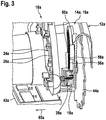
- the Figure 3 shows part of the portable machine tool 10a in a perspective partial sectional illustration.
- the setting unit 16a has a securing element 18a arranged on the guide unit 14a.
- the securing element 18a is arranged on the guide element 50a.
- the securing element 18a is designed as a latching element in the present case.
- the securing element 18a is provided to secure a position of the housing unit 12a.
- the securing element 18a is provided to limit a movement of the housing unit 12a, in particular relative to the base plate 42a.
- the securing element 18a is mounted displaceably in a direction 60a parallel to the pivot axis 46a.
- the guide element 50a has a multiplicity of latching elements 56a, 58a for the securing element 18a, which for the sake of clarity are not all provided with reference symbols.
- the latching elements 56a, 58a are arranged along the guide slot 52a.
- the latching elements 56a, 58a define different latching positions of the securing element 18a, which correspond to different first cutting parameters.
- the securing element 18a is connected in a secured position to at least one of the latching elements 56a, 58a. In the Figure 3 the securing element 18a is shown in the secured position.
- the portable machine tool 10a has a restoring element 38a which is provided to move the securing element 18a back into an initial position after it has been actuated.
- the starting position corresponds to the secured position.
- the restoring element 38a is designed as a spring.
- the restoring element 38a is generated a securing force which presses the securing element 18a towards the guide element 50a and / or against the guide element 50a.
- the portable machine tool 10a has an operating unit 20a which comprises at least one operating element 22a at least for acting on the securing element 18a.
- the operating element 22a is designed as a pivotably mounted push button. When actuated, the operating element 22a is pressed upwards away from the base plate 42a, for example with the thumb of a user.
- the portable machine tool 10a has an at least partially flexible transmission unit 24a, which is provided to transmit a movement of the operating element 22a to the securing element 18a.
- a tensile force generated by pressing against the operating element 22a is transmitted from the transmission unit 24a to the securing element 18a.
- the transmission unit 24a is provided to move the securing element 18a in accordance with the movement of the operating element 22a.
- the transmission unit 24a follows a curved course at least in sections.
- the transmission unit 24a has a transmission element 26a for connecting the operating element 22a and the securing element 18a, which transmission element is designed as a flexible tensile force transmission element.
- the transmission element 26a is designed as a cable pull. It is conceivable that a transmission element is designed as a Bowden cable.
- a transmission unit is at least partially fluid-containing, in particular fluid-carrying. In this case in particular, a transmission element can be designed as an incompressible pressure force transmission element, for example as a filled fluid line.
- the transmission element 26a is directly connected to the securing element 18a and the operating element 22a.
- the transmission element 26a is connected to a suspension lever 54a of the operating element 22a.
- the transmission element 26a is connected to the securing element 18a. Due to the direct connection of the control element 22a and the securing element 18a, the resetting element 38a moves the operating element 22a back into its starting position after an actuation.
- the transmission element 26a transmits a restoring force of the restoring element 38a to the operating element 22a.
- At least a large part of the transmission unit 24a is arranged in the housing unit 12a. At least a large part of the transmission unit 24a is arranged within the handle housing section 30a.
- the operating element 22a is assigned to the handle housing section 30a.
- the handle housing section 30a has a receiving opening 62a in which the operating element 22a is arranged.
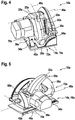
- the Figure 4 shows the portable machine tool 10a in a perspective view.
- the Figure 5 shows the portable machine tool 10a in a further perspective view.
- the additional handle 64a is for the sake of clarity in the Figures 5 and 6th not shown.
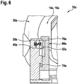
- the Figure 6 shows a further part of the portable machine tool 10a in a schematic sectional illustration.
- the guide unit 14a has a first further guide element 66a and a second further guide element 68a.
- the first further guide element 66a and the second further guide element 68a are provided for guiding a pivoting movement about the further pivot axis 48a.
- the setting unit 16a has a further securing element 32a.
- the further securing element 32a is arranged on the guide unit 14a.
- the further securing element 32a is arranged on the first further guide element 66a.
- the further securing element 32a is latched to the first further guide element 66a, analogously to the securing element 18a and the guide element 50a.
- the portable machine tool 10a has a further restoring element 40a which presses the further securing element 32a into a secured position against the first further guide element 66a.
- the setting unit 16a also has a second further securing element, not shown, which is assigned to the second further guide element 68a.
- the first further guide element 66a and the second further guide element 68a define a plurality of different latching positions for the further securing element 32a and for the second further securing element, which correspond to different second cutting parameters.
- the first further guide element 66a has a guide slot 74a.
- the second further guide element 68a has a latching rail 76a.
- the portable machine tool 10a has a further transmission unit 36a.
- the further transmission unit 36a is assigned to an adaptation of the second cutting parameter.
- the operating unit 20a has a further operating element 34a to which the further transmission unit 36a is assigned.
- the further operating element 34a is assigned to the base plate 42a.
- the further operating element 34a is arranged on a rear side 72a of the portable machine tool 10a.
- the further operating element 34a is arranged on the base plate 42a.
- the further operating element 34a is designed as a rocker arm.
- the further operating element 34a can be operated independently of the operating element 22a.
- the further transmission unit 36a has a first further transmission element 28a and a second further transmission element 70a, which are connected to the further securing element 32a and to the second further securing element, respectively.
- the further transmission elements 28a, 70a are also designed as cables, in particular as Bowden cables, but can also be fluid lines, for example.
- the Figure 7 shows a further portable machine tool 10b in a perspective side view.
- the further portable machine tool 10b analogously to the portable machine tool 10a, has a setting unit 16b and an operating unit 20b for setting a first cutting parameter and a second cutting parameter.
- the first cutting parameter can be set by means of an operating element 22b of the operating unit 20b.
- the second cutting parameter can be set by means of a further operating element 34b of the operating unit 20b.
- the further operating element 34b is arranged on a front side 78b of the further portable machine tool 10b.
- the further operating element 34b is arranged on a base plate 42b of the further portable machine tool 10b.
- the operating element 22b is provided for releasing and securing an adjustment of both cutting parameters.
- a corresponding operating element is advantageously connected to all relevant security elements via a corresponding transmission unit.
Landscapes
- Life Sciences & Earth Sciences (AREA)
- Engineering & Computer Science (AREA)
- Mechanical Engineering (AREA)
- Wood Science & Technology (AREA)
- Forests & Forestry (AREA)
- Sawing (AREA)
- Surgical Instruments (AREA)
Claims (8)
- Machine-outil portable, notamment scie circulaire, munie d'une unité de boîtier (12a), munie d'au moins une unité de guidage (14a) au moins pour un guidage d'un mouvement de basculement de l'unité de boîtier (12a), munie d'au moins une unité d'ajustement (16a ; 16b) pour un ajustement d'au moins un paramètre de coupe, notamment d'une profondeur de coupe et/ou d'un angle de coupe, qui comprend au moins un élément d'assujettissement (18a, 32a) agencé sur l'unité de guidage (14a ; 14b) pour un assujettissement d'une position de l'unité de boîtier (12a) et/ou pour une limitation d'un mouvement de l'unité de boîtier (12a), munie d'au moins une unité de commande (20a ; 20b), qui comprend au moins un élément de commande (22a, 34a ; 22b, 34b) au moins pour agir sur l'élément d'assujettissement (18a, 32a), et munie d'au moins une unité de transmission (24a, 36a ; 24b, 36b) au moins partiellement souple en flexion, qui est prévue pour transmettre un mouvement de l'élément de commande (22a, 34a ; 22b, 34b) à l'élément d'assujettissement (18a, 32a), l'unité de guidage (14a) comprenant au moins un élément de guidage pour l'unité de boîtier (12a), qui est configuré sous la forme d'une coulisse, d'une rainure de guidage ou sous la forme d'un rail de guidage, caractérisée en ce que l'élément d'assujettissement (18a, 32a) est configuré sous la forme d'un élément encliquetable, l'unité de transmission (24a, 36a ; 24b, 36b) comprenant au moins un élément de transmission (26a, 28a, 70a) pour un raccordement de l'élément de commande (22a, 34a ; 22b, 34b) et de l'élément d'assujettissement (18a, 32a), qui est configuré en tant qu'élément de transmission de force de traction souple en flexion sous la forme d'un câble de traction et/ou d'un câble Bowden ou en tant qu'élément de transmission de force de pression incompressible, l'unité de transmission (24a, 36a ; 24b, 36b) étant prévue pour la transmission d'au moins une partie d'une force de commande agissant sur l'élément de commande (22a, 34a ; 22b, 34b) en tant que force d'actionnement sur l'élément d'assujettissement (18a, 32a), et l'unité de transmission (24a, 36a ; 24b, 36b) étant agencée au moins en grande partie à l'intérieur de l'unité de boîtier (12a).
- Machine-outil portable selon la revendication 1, caractérisée en ce que l'unité de transmission (24a, 36a) comprend au moins un élément de transmission (26a, 28a, 70a), qui est raccordé directement à l'élément d'assujettissement (18a, 32a) et à l'élément de commande (22a, 34a).
- Machine-outil portable selon l'une quelconque des revendications précédentes, caractérisée en ce que l'unité de boîtier (12a) comprend au moins une section de boîtier de préhension (30a) et l'unité de transmission (24a) est au moins partiellement agencée dans la section de boîtier de préhension (30a).
- Machine-outil portable selon la revendication 3, caractérisée en ce que l'élément de commande (22a) est associé à la section de boîtier de préhension (30a).
- Machine-outil portable selon l'une quelconque des revendications précédentes, caractérisée par au moins un élément de rappel (38a, 40a), notamment un ressort, qui est prévu pour ramener l'élément d'assujettissement (18a, 32a) et l'élément de commande (22a, 34a) dans une position initiale après un actionnement.
- Machine-outil portable selon l'une quelconque des revendications précédentes, caractérisée par au moins une unité de transmission supplémentaire (36a), l'unité de transmission (24a) et l'unité de transmission supplémentaire (36a) étant associées à une adaptation de différents paramètres de coupe, notamment de la profondeur de coupe et de l'angle de coupe.
- Machine-outil portable selon la revendication 6, caractérisée en ce que l'unité de commande (20a) comprend au moins un élément de commande supplémentaire (34a), qui est associé à l'unité de transmission supplémentaire (36a).
- Machine-outil portable selon la revendication 7, caractérisée par au moins une plaque de base (42a ; 42b), qui est associée à l'élément de commande supplémentaire (34a ; 34b).
Applications Claiming Priority (1)
| Application Number | Priority Date | Filing Date | Title |
|---|---|---|---|
| DE102017202197.7A DE102017202197A1 (de) | 2017-02-13 | 2017-02-13 | Tragbare Werkzeugmaschine |
Publications (2)
| Publication Number | Publication Date |
|---|---|
| EP3360657A1 EP3360657A1 (fr) | 2018-08-15 |
| EP3360657B1 true EP3360657B1 (fr) | 2021-11-03 |
Family
ID=61017835
Family Applications (1)
| Application Number | Title | Priority Date | Filing Date |
|---|---|---|---|
| EP18152672.4A Active EP3360657B1 (fr) | 2017-02-13 | 2018-01-22 | Machine-outil portable |
Country Status (3)
| Country | Link |
|---|---|
| EP (1) | EP3360657B1 (fr) |
| CN (1) | CN108422493B (fr) |
| DE (1) | DE102017202197A1 (fr) |
Families Citing this family (3)
| Publication number | Priority date | Publication date | Assignee | Title |
|---|---|---|---|---|
| JP7249797B2 (ja) * | 2019-02-08 | 2023-03-31 | 株式会社マキタ | 携帯用加工機 |
| DE102019208919A1 (de) * | 2019-06-19 | 2020-12-24 | Robert Bosch Gmbh | Sägewerkzeugmaschine |
| DE102023208977A1 (de) | 2023-09-15 | 2025-03-20 | Robert Bosch Gesellschaft mit beschränkter Haftung | Handkreissäge mit einer Tiefeneinstellvorrichtung |
Family Cites Families (10)
| Publication number | Priority date | Publication date | Assignee | Title |
|---|---|---|---|---|
| DE1503974A1 (de) | 1966-02-05 | 1970-07-30 | Metabowerke Kg | Handkreissaege |
| GB2059338B (en) | 1979-09-19 | 1983-08-17 | Albery W | Saw |
| DE3615848C3 (de) * | 1986-05-10 | 1994-05-11 | Festo Kg | Für Trennarbeiten verwendbare Handwerkzeugmaschine wie Handkreissäge, Trennschleifgerät od. dgl. |
| US4840431A (en) * | 1988-07-26 | 1989-06-20 | Diamond Products, Inc. | Portable rotary power saw |
| GB2258188B (en) | 1991-07-31 | 1994-05-11 | William Albery | Portable saws |
| US20070017326A1 (en) * | 2005-07-20 | 2007-01-25 | One World Technologies Limited | Laser generator mounted on a fixed component of a handheld cutting device |
| DE202007006291U1 (de) * | 2007-04-30 | 2008-09-04 | Metabowerke Gmbh | Sägeeinrichtung mit Verstellhalterung für das Sägeaggregat |
| CN201483079U (zh) * | 2009-06-01 | 2010-05-26 | 南京德朔实业有限公司 | 直流电圆锯 |
| DE102014010484A1 (de) | 2014-07-15 | 2016-01-21 | Festool Gmbh | Hand-Trennmaschine mit einer fixierbaren Gehrungslageranordnung |
| DE102014010487A1 (de) * | 2014-07-15 | 2016-01-21 | Festool Gmbh | Hand-Trennmaschine mit zwei Gehrungslagern |
-
2017
- 2017-02-13 DE DE102017202197.7A patent/DE102017202197A1/de not_active Withdrawn
-
2018
- 2018-01-22 EP EP18152672.4A patent/EP3360657B1/fr active Active
- 2018-02-13 CN CN201810148901.3A patent/CN108422493B/zh active Active
Also Published As
| Publication number | Publication date |
|---|---|
| EP3360657A1 (fr) | 2018-08-15 |
| DE102017202197A1 (de) | 2018-08-16 |
| CN108422493A (zh) | 2018-08-21 |
| CN108422493B (zh) | 2022-05-27 |
Similar Documents
| Publication | Publication Date | Title |
|---|---|---|
| EP2374657B1 (fr) | Accoudoir et poste de commande doté d'un tel accoudoir | |
| EP3360657B1 (fr) | Machine-outil portable | |
| DE102018117203B4 (de) | Messer | |
| EP2020280A2 (fr) | Dispositif de recouvrement d'une machine-outil | |
| DE102014201920A1 (de) | Handwerkzeugmaschinenbetätigungselement für eine Stichsäge, sowie Stichsäge | |
| EP2601018B1 (fr) | Machine-outil electrique avec poignée antivibration | |
| EP2841237B1 (fr) | Machine-outil pouvant être guidée manuellement et comportant un carter | |
| DE29920199U1 (de) | Spannwerkzeug | |
| EP2957391A1 (fr) | Appareil de travail portatif | |
| WO2014000923A1 (fr) | Dispositif de séparation pour machine-outil, doté d'une unité de protection | |
| WO2018234311A2 (fr) | Bride de fixation et procédé de fonctionnement d'une bride de fixation | |
| EP0940203A2 (fr) | Outil de rivetage à main pour rivets aveugles | |
| EP1997590B1 (fr) | Appareil de pose manuel doté d'un raccordement pour un dispositif de positionnement | |
| DE102015112724A1 (de) | Stanzbacken und Stanzgerät mit einer Stanzhülse und einer Stanzöffnung | |
| EP1319456A1 (fr) | Découpeur de câbles | |
| EP2724816B1 (fr) | Machine-outil motorisée, en particulier meuleuse d'angle ou meuleuse droite | |
| EP1997589B1 (fr) | Dispositif de positionnement doté d'une commutation de déclenchement pour un appareil de pose manuel | |
| EP4059666A2 (fr) | Appareil de travail guidé à la main | |
| EP1466690B1 (fr) | Scie sauteuse en forme de sabre avec dispositif d'ajustage pour un guide | |
| EP2625007A1 (fr) | Dispositif de guidage de pièce | |
| EP2890525A2 (fr) | Système de machine-outil | |
| DE102021124291A1 (de) | Chirurgisches Instrument | |
| DE102023204786A1 (de) | Verbindungsvorrichtung, Verlängerungsstück, Werkzeugaufsatz und Werkzeugsystem | |
| WO2017216252A1 (fr) | Instrument chirurgical | |
| DE102016102101A1 (de) | Universalzange mit verstärkter Sicherung |
Legal Events
| Date | Code | Title | Description |
|---|---|---|---|
| PUAI | Public reference made under article 153(3) epc to a published international application that has entered the european phase |
Free format text: ORIGINAL CODE: 0009012 |
|
| STAA | Information on the status of an ep patent application or granted ep patent |
Free format text: STATUS: THE APPLICATION HAS BEEN PUBLISHED |
|
| AK | Designated contracting states |
Kind code of ref document: A1 Designated state(s): AL AT BE BG CH CY CZ DE DK EE ES FI FR GB GR HR HU IE IS IT LI LT LU LV MC MK MT NL NO PL PT RO RS SE SI SK SM TR |
|
| AX | Request for extension of the european patent |
Extension state: BA ME |
|
| STAA | Information on the status of an ep patent application or granted ep patent |
Free format text: STATUS: REQUEST FOR EXAMINATION WAS MADE |
|
| 17P | Request for examination filed |
Effective date: 20190215 |
|
| RBV | Designated contracting states (corrected) |
Designated state(s): AL AT BE BG CH CY CZ DE DK EE ES FI FR GB GR HR HU IE IS IT LI LT LU LV MC MK MT NL NO PL PT RO RS SE SI SK SM TR |
|
| RAP1 | Party data changed (applicant data changed or rights of an application transferred) |
Owner name: ROBERT BOSCH GMBH |
|
| GRAP | Despatch of communication of intention to grant a patent |
Free format text: ORIGINAL CODE: EPIDOSNIGR1 |
|
| STAA | Information on the status of an ep patent application or granted ep patent |
Free format text: STATUS: GRANT OF PATENT IS INTENDED |
|
| INTG | Intention to grant announced |
Effective date: 20210719 |
|
| GRAS | Grant fee paid |
Free format text: ORIGINAL CODE: EPIDOSNIGR3 |
|
| GRAA | (expected) grant |
Free format text: ORIGINAL CODE: 0009210 |
|
| STAA | Information on the status of an ep patent application or granted ep patent |
Free format text: STATUS: THE PATENT HAS BEEN GRANTED |
|
| AK | Designated contracting states |
Kind code of ref document: B1 Designated state(s): AL AT BE BG CH CY CZ DE DK EE ES FI FR GB GR HR HU IE IS IT LI LT LU LV MC MK MT NL NO PL PT RO RS SE SI SK SM TR |
|
| REG | Reference to a national code |
Ref country code: GB Ref legal event code: FG4D Free format text: NOT ENGLISH |
|
| REG | Reference to a national code |
Ref country code: AT Ref legal event code: REF Ref document number: 1443567 Country of ref document: AT Kind code of ref document: T Effective date: 20211115 Ref country code: CH Ref legal event code: EP |
|
| REG | Reference to a national code |
Ref country code: DE Ref legal event code: R096 Ref document number: 502018007640 Country of ref document: DE |
|
| REG | Reference to a national code |
Ref country code: IE Ref legal event code: FG4D Free format text: LANGUAGE OF EP DOCUMENT: GERMAN |
|
| REG | Reference to a national code |
Ref country code: LT Ref legal event code: MG9D |
|
| REG | Reference to a national code |
Ref country code: NL Ref legal event code: MP Effective date: 20211103 |
|
| PG25 | Lapsed in a contracting state [announced via postgrant information from national office to epo] |
Ref country code: RS Free format text: LAPSE BECAUSE OF FAILURE TO SUBMIT A TRANSLATION OF THE DESCRIPTION OR TO PAY THE FEE WITHIN THE PRESCRIBED TIME-LIMIT Effective date: 20211103 Ref country code: LT Free format text: LAPSE BECAUSE OF FAILURE TO SUBMIT A TRANSLATION OF THE DESCRIPTION OR TO PAY THE FEE WITHIN THE PRESCRIBED TIME-LIMIT Effective date: 20211103 Ref country code: FI Free format text: LAPSE BECAUSE OF FAILURE TO SUBMIT A TRANSLATION OF THE DESCRIPTION OR TO PAY THE FEE WITHIN THE PRESCRIBED TIME-LIMIT Effective date: 20211103 Ref country code: BG Free format text: LAPSE BECAUSE OF FAILURE TO SUBMIT A TRANSLATION OF THE DESCRIPTION OR TO PAY THE FEE WITHIN THE PRESCRIBED TIME-LIMIT Effective date: 20220203 |
|
| PG25 | Lapsed in a contracting state [announced via postgrant information from national office to epo] |
Ref country code: IS Free format text: LAPSE BECAUSE OF FAILURE TO SUBMIT A TRANSLATION OF THE DESCRIPTION OR TO PAY THE FEE WITHIN THE PRESCRIBED TIME-LIMIT Effective date: 20220303 Ref country code: SE Free format text: LAPSE BECAUSE OF FAILURE TO SUBMIT A TRANSLATION OF THE DESCRIPTION OR TO PAY THE FEE WITHIN THE PRESCRIBED TIME-LIMIT Effective date: 20211103 Ref country code: PT Free format text: LAPSE BECAUSE OF FAILURE TO SUBMIT A TRANSLATION OF THE DESCRIPTION OR TO PAY THE FEE WITHIN THE PRESCRIBED TIME-LIMIT Effective date: 20220303 Ref country code: PL Free format text: LAPSE BECAUSE OF FAILURE TO SUBMIT A TRANSLATION OF THE DESCRIPTION OR TO PAY THE FEE WITHIN THE PRESCRIBED TIME-LIMIT Effective date: 20211103 Ref country code: NO Free format text: LAPSE BECAUSE OF FAILURE TO SUBMIT A TRANSLATION OF THE DESCRIPTION OR TO PAY THE FEE WITHIN THE PRESCRIBED TIME-LIMIT Effective date: 20220203 Ref country code: NL Free format text: LAPSE BECAUSE OF FAILURE TO SUBMIT A TRANSLATION OF THE DESCRIPTION OR TO PAY THE FEE WITHIN THE PRESCRIBED TIME-LIMIT Effective date: 20211103 Ref country code: LV Free format text: LAPSE BECAUSE OF FAILURE TO SUBMIT A TRANSLATION OF THE DESCRIPTION OR TO PAY THE FEE WITHIN THE PRESCRIBED TIME-LIMIT Effective date: 20211103 Ref country code: HR Free format text: LAPSE BECAUSE OF FAILURE TO SUBMIT A TRANSLATION OF THE DESCRIPTION OR TO PAY THE FEE WITHIN THE PRESCRIBED TIME-LIMIT Effective date: 20211103 Ref country code: GR Free format text: LAPSE BECAUSE OF FAILURE TO SUBMIT A TRANSLATION OF THE DESCRIPTION OR TO PAY THE FEE WITHIN THE PRESCRIBED TIME-LIMIT Effective date: 20220204 Ref country code: ES Free format text: LAPSE BECAUSE OF FAILURE TO SUBMIT A TRANSLATION OF THE DESCRIPTION OR TO PAY THE FEE WITHIN THE PRESCRIBED TIME-LIMIT Effective date: 20211103 |
|
| PG25 | Lapsed in a contracting state [announced via postgrant information from national office to epo] |
Ref country code: SM Free format text: LAPSE BECAUSE OF FAILURE TO SUBMIT A TRANSLATION OF THE DESCRIPTION OR TO PAY THE FEE WITHIN THE PRESCRIBED TIME-LIMIT Effective date: 20211103 Ref country code: SK Free format text: LAPSE BECAUSE OF FAILURE TO SUBMIT A TRANSLATION OF THE DESCRIPTION OR TO PAY THE FEE WITHIN THE PRESCRIBED TIME-LIMIT Effective date: 20211103 Ref country code: RO Free format text: LAPSE BECAUSE OF FAILURE TO SUBMIT A TRANSLATION OF THE DESCRIPTION OR TO PAY THE FEE WITHIN THE PRESCRIBED TIME-LIMIT Effective date: 20211103 Ref country code: EE Free format text: LAPSE BECAUSE OF FAILURE TO SUBMIT A TRANSLATION OF THE DESCRIPTION OR TO PAY THE FEE WITHIN THE PRESCRIBED TIME-LIMIT Effective date: 20211103 Ref country code: DK Free format text: LAPSE BECAUSE OF FAILURE TO SUBMIT A TRANSLATION OF THE DESCRIPTION OR TO PAY THE FEE WITHIN THE PRESCRIBED TIME-LIMIT Effective date: 20211103 Ref country code: CZ Free format text: LAPSE BECAUSE OF FAILURE TO SUBMIT A TRANSLATION OF THE DESCRIPTION OR TO PAY THE FEE WITHIN THE PRESCRIBED TIME-LIMIT Effective date: 20211103 |
|
| REG | Reference to a national code |
Ref country code: DE Ref legal event code: R097 Ref document number: 502018007640 Country of ref document: DE |
|
| PG25 | Lapsed in a contracting state [announced via postgrant information from national office to epo] |
Ref country code: MC Free format text: LAPSE BECAUSE OF FAILURE TO SUBMIT A TRANSLATION OF THE DESCRIPTION OR TO PAY THE FEE WITHIN THE PRESCRIBED TIME-LIMIT Effective date: 20211103 |
|
| REG | Reference to a national code |
Ref country code: CH Ref legal event code: PL |
|
| PLBE | No opposition filed within time limit |
Free format text: ORIGINAL CODE: 0009261 |
|
| STAA | Information on the status of an ep patent application or granted ep patent |
Free format text: STATUS: NO OPPOSITION FILED WITHIN TIME LIMIT |
|
| REG | Reference to a national code |
Ref country code: BE Ref legal event code: MM Effective date: 20220131 |
|
| 26N | No opposition filed |
Effective date: 20220804 |
|
| GBPC | Gb: european patent ceased through non-payment of renewal fee |
Effective date: 20220203 |
|
| PG25 | Lapsed in a contracting state [announced via postgrant information from national office to epo] |
Ref country code: LU Free format text: LAPSE BECAUSE OF NON-PAYMENT OF DUE FEES Effective date: 20220122 Ref country code: AL Free format text: LAPSE BECAUSE OF FAILURE TO SUBMIT A TRANSLATION OF THE DESCRIPTION OR TO PAY THE FEE WITHIN THE PRESCRIBED TIME-LIMIT Effective date: 20211103 |
|
| PG25 | Lapsed in a contracting state [announced via postgrant information from national office to epo] |
Ref country code: SI Free format text: LAPSE BECAUSE OF FAILURE TO SUBMIT A TRANSLATION OF THE DESCRIPTION OR TO PAY THE FEE WITHIN THE PRESCRIBED TIME-LIMIT Effective date: 20211103 Ref country code: FR Free format text: LAPSE BECAUSE OF NON-PAYMENT OF DUE FEES Effective date: 20220131 Ref country code: BE Free format text: LAPSE BECAUSE OF NON-PAYMENT OF DUE FEES Effective date: 20220131 |
|
| PG25 | Lapsed in a contracting state [announced via postgrant information from national office to epo] |
Ref country code: LI Free format text: LAPSE BECAUSE OF NON-PAYMENT OF DUE FEES Effective date: 20220131 Ref country code: CH Free format text: LAPSE BECAUSE OF NON-PAYMENT OF DUE FEES Effective date: 20220131 |
|
| PG25 | Lapsed in a contracting state [announced via postgrant information from national office to epo] |
Ref country code: IE Free format text: LAPSE BECAUSE OF NON-PAYMENT OF DUE FEES Effective date: 20220122 Ref country code: GB Free format text: LAPSE BECAUSE OF NON-PAYMENT OF DUE FEES Effective date: 20220203 |
|
| PG25 | Lapsed in a contracting state [announced via postgrant information from national office to epo] |
Ref country code: IT Free format text: LAPSE BECAUSE OF FAILURE TO SUBMIT A TRANSLATION OF THE DESCRIPTION OR TO PAY THE FEE WITHIN THE PRESCRIBED TIME-LIMIT Effective date: 20211103 |
|
| REG | Reference to a national code |
Ref country code: AT Ref legal event code: MM01 Ref document number: 1443567 Country of ref document: AT Kind code of ref document: T Effective date: 20230122 |
|
| PG25 | Lapsed in a contracting state [announced via postgrant information from national office to epo] |
Ref country code: HU Free format text: LAPSE BECAUSE OF FAILURE TO SUBMIT A TRANSLATION OF THE DESCRIPTION OR TO PAY THE FEE WITHIN THE PRESCRIBED TIME-LIMIT; INVALID AB INITIO Effective date: 20180122 |
|
| PG25 | Lapsed in a contracting state [announced via postgrant information from national office to epo] |
Ref country code: AT Free format text: LAPSE BECAUSE OF NON-PAYMENT OF DUE FEES Effective date: 20230122 |
|
| PG25 | Lapsed in a contracting state [announced via postgrant information from national office to epo] |
Ref country code: MK Free format text: LAPSE BECAUSE OF FAILURE TO SUBMIT A TRANSLATION OF THE DESCRIPTION OR TO PAY THE FEE WITHIN THE PRESCRIBED TIME-LIMIT Effective date: 20211103 Ref country code: CY Free format text: LAPSE BECAUSE OF FAILURE TO SUBMIT A TRANSLATION OF THE DESCRIPTION OR TO PAY THE FEE WITHIN THE PRESCRIBED TIME-LIMIT Effective date: 20211103 Ref country code: AT Free format text: LAPSE BECAUSE OF NON-PAYMENT OF DUE FEES Effective date: 20230122 |
|
| PG25 | Lapsed in a contracting state [announced via postgrant information from national office to epo] |
Ref country code: MT Free format text: LAPSE BECAUSE OF FAILURE TO SUBMIT A TRANSLATION OF THE DESCRIPTION OR TO PAY THE FEE WITHIN THE PRESCRIBED TIME-LIMIT Effective date: 20211103 |
|
| PG25 | Lapsed in a contracting state [announced via postgrant information from national office to epo] |
Ref country code: TR Free format text: LAPSE BECAUSE OF FAILURE TO SUBMIT A TRANSLATION OF THE DESCRIPTION OR TO PAY THE FEE WITHIN THE PRESCRIBED TIME-LIMIT Effective date: 20211103 |
|
| PGFP | Annual fee paid to national office [announced via postgrant information from national office to epo] |
Ref country code: DE Payment date: 20260319 Year of fee payment: 9 |
|
| PGFP | Annual fee paid to national office [announced via postgrant information from national office to epo] |
Ref country code: AT Payment date: 20260410 Year of fee payment: 5 |