EP3360676B1 - Dispositif et procédé de fabrication de récipients en matériau de papier ou en matériau similaire au papier et récipient - Google Patents
Dispositif et procédé de fabrication de récipients en matériau de papier ou en matériau similaire au papier et récipient Download PDFInfo
- Publication number
- EP3360676B1 EP3360676B1 EP18152135.2A EP18152135A EP3360676B1 EP 3360676 B1 EP3360676 B1 EP 3360676B1 EP 18152135 A EP18152135 A EP 18152135A EP 3360676 B1 EP3360676 B1 EP 3360676B1
- Authority
- EP
- European Patent Office
- Prior art keywords
- segment
- region
- overlap
- skirt
- edge
- Prior art date
- Legal status (The legal status is an assumption and is not a legal conclusion. Google has not performed a legal analysis and makes no representation as to the accuracy of the status listed.)
- Active
Links
Images


Classifications
-
- B—PERFORMING OPERATIONS; TRANSPORTING
- B65—CONVEYING; PACKING; STORING; HANDLING THIN OR FILAMENTARY MATERIAL
- B65D—CONTAINERS FOR STORAGE OR TRANSPORT OF ARTICLES OR MATERIALS, e.g. BAGS, BARRELS, BOTTLES, BOXES, CANS, CARTONS, CRATES, DRUMS, JARS, TANKS, HOPPERS, FORWARDING CONTAINERS; ACCESSORIES, CLOSURES, OR FITTINGS THEREFOR; PACKAGING ELEMENTS; PACKAGES
- B65D3/00—Rigid or semi-rigid containers having bodies or peripheral walls of curved or partially-curved cross-section made by winding or bending paper without folding along defined lines
- B65D3/02—Rigid or semi-rigid containers having bodies or peripheral walls of curved or partially-curved cross-section made by winding or bending paper without folding along defined lines characterised by shape
-
- B—PERFORMING OPERATIONS; TRANSPORTING
- B31—MAKING ARTICLES OF PAPER, CARDBOARD OR MATERIAL WORKED IN A MANNER ANALOGOUS TO PAPER; WORKING PAPER, CARDBOARD OR MATERIAL WORKED IN A MANNER ANALOGOUS TO PAPER
- B31C—MAKING WOUND ARTICLES, e.g. WOUND TUBES, OF PAPER, CARDBOARD OR MATERIAL WORKED IN A MANNER ANALOGOUS TO PAPER
- B31C7/00—Making conical articles by winding
- B31C7/02—Forming truncated cones
-
- B—PERFORMING OPERATIONS; TRANSPORTING
- B65—CONVEYING; PACKING; STORING; HANDLING THIN OR FILAMENTARY MATERIAL
- B65D—CONTAINERS FOR STORAGE OR TRANSPORT OF ARTICLES OR MATERIALS, e.g. BAGS, BARRELS, BOTTLES, BOXES, CANS, CARTONS, CRATES, DRUMS, JARS, TANKS, HOPPERS, FORWARDING CONTAINERS; ACCESSORIES, CLOSURES, OR FITTINGS THEREFOR; PACKAGING ELEMENTS; PACKAGES
- B65D3/00—Rigid or semi-rigid containers having bodies or peripheral walls of curved or partially-curved cross-section made by winding or bending paper without folding along defined lines
- B65D3/02—Rigid or semi-rigid containers having bodies or peripheral walls of curved or partially-curved cross-section made by winding or bending paper without folding along defined lines characterised by shape
- B65D3/06—Rigid or semi-rigid containers having bodies or peripheral walls of curved or partially-curved cross-section made by winding or bending paper without folding along defined lines characterised by shape essentially conical or frusto-conical
-
- B—PERFORMING OPERATIONS; TRANSPORTING
- B31—MAKING ARTICLES OF PAPER, CARDBOARD OR MATERIAL WORKED IN A MANNER ANALOGOUS TO PAPER; WORKING PAPER, CARDBOARD OR MATERIAL WORKED IN A MANNER ANALOGOUS TO PAPER
- B31B—MAKING CONTAINERS OF PAPER, CARDBOARD OR MATERIAL WORKED IN A MANNER ANALOGOUS TO PAPER
- B31B50/00—Making rigid or semi-rigid containers, e.g. boxes or cartons
- B31B50/59—Shaping sheet material under pressure
-
- B—PERFORMING OPERATIONS; TRANSPORTING
- B31—MAKING ARTICLES OF PAPER, CARDBOARD OR MATERIAL WORKED IN A MANNER ANALOGOUS TO PAPER; WORKING PAPER, CARDBOARD OR MATERIAL WORKED IN A MANNER ANALOGOUS TO PAPER
- B31B—MAKING CONTAINERS OF PAPER, CARDBOARD OR MATERIAL WORKED IN A MANNER ANALOGOUS TO PAPER
- B31B50/00—Making rigid or semi-rigid containers, e.g. boxes or cartons
- B31B50/60—Uniting opposed surfaces or edges; Taping
- B31B50/64—Uniting opposed surfaces or edges; Taping by applying heat or pressure, e.g. by welding
- B31B50/642—Uniting opposed surfaces or edges; Taping by applying heat or pressure, e.g. by welding using sealing jaws or sealing dies
-
- B—PERFORMING OPERATIONS; TRANSPORTING
- B31—MAKING ARTICLES OF PAPER, CARDBOARD OR MATERIAL WORKED IN A MANNER ANALOGOUS TO PAPER; WORKING PAPER, CARDBOARD OR MATERIAL WORKED IN A MANNER ANALOGOUS TO PAPER
- B31C—MAKING WOUND ARTICLES, e.g. WOUND TUBES, OF PAPER, CARDBOARD OR MATERIAL WORKED IN A MANNER ANALOGOUS TO PAPER
- B31C3/00—Making tubes or pipes by feeding obliquely to the winding mandrel centre line
-
- B—PERFORMING OPERATIONS; TRANSPORTING
- B31—MAKING ARTICLES OF PAPER, CARDBOARD OR MATERIAL WORKED IN A MANNER ANALOGOUS TO PAPER; WORKING PAPER, CARDBOARD OR MATERIAL WORKED IN A MANNER ANALOGOUS TO PAPER
- B31C—MAKING WOUND ARTICLES, e.g. WOUND TUBES, OF PAPER, CARDBOARD OR MATERIAL WORKED IN A MANNER ANALOGOUS TO PAPER
- B31C7/00—Making conical articles by winding
- B31C7/02—Forming truncated cones
- B31C7/04—Forming truncated cones on two or more mandrels
- B31C7/06—Forming truncated cones on two or more mandrels and inserting into a cone end a bottom to form a container
-
- B—PERFORMING OPERATIONS; TRANSPORTING
- B31—MAKING ARTICLES OF PAPER, CARDBOARD OR MATERIAL WORKED IN A MANNER ANALOGOUS TO PAPER; WORKING PAPER, CARDBOARD OR MATERIAL WORKED IN A MANNER ANALOGOUS TO PAPER
- B31D—MAKING ARTICLES OF PAPER, CARDBOARD OR MATERIAL WORKED IN A MANNER ANALOGOUS TO PAPER, NOT PROVIDED FOR IN SUBCLASSES B31B OR B31C
- B31D5/00—Multiple-step processes for making three-dimensional [3D] articles
- B31D5/02—Multiple-step processes for making three-dimensional [3D] articles including pressing
-
- B—PERFORMING OPERATIONS; TRANSPORTING
- B31—MAKING ARTICLES OF PAPER, CARDBOARD OR MATERIAL WORKED IN A MANNER ANALOGOUS TO PAPER; WORKING PAPER, CARDBOARD OR MATERIAL WORKED IN A MANNER ANALOGOUS TO PAPER
- B31F—MECHANICAL WORKING OR DEFORMATION OF PAPER, CARDBOARD OR MATERIAL WORKED IN A MANNER ANALOGOUS TO PAPER
- B31F1/00—Mechanical deformation without removing material, e.g. in combination with laminating
- B31F1/008—Shaping of tube ends, e.g. flanging, belling, closing, rim-rolling or corrugating; Fixing elements to tube ends
- B31F1/0083—Closing
-
- B—PERFORMING OPERATIONS; TRANSPORTING
- B31—MAKING ARTICLES OF PAPER, CARDBOARD OR MATERIAL WORKED IN A MANNER ANALOGOUS TO PAPER; WORKING PAPER, CARDBOARD OR MATERIAL WORKED IN A MANNER ANALOGOUS TO PAPER
- B31F—MECHANICAL WORKING OR DEFORMATION OF PAPER, CARDBOARD OR MATERIAL WORKED IN A MANNER ANALOGOUS TO PAPER
- B31F1/00—Mechanical deformation without removing material, e.g. in combination with laminating
- B31F1/008—Shaping of tube ends, e.g. flanging, belling, closing, rim-rolling or corrugating; Fixing elements to tube ends
- B31F1/0087—Rim-rolling
-
- B—PERFORMING OPERATIONS; TRANSPORTING
- B31—MAKING ARTICLES OF PAPER, CARDBOARD OR MATERIAL WORKED IN A MANNER ANALOGOUS TO PAPER; WORKING PAPER, CARDBOARD OR MATERIAL WORKED IN A MANNER ANALOGOUS TO PAPER
- B31F—MECHANICAL WORKING OR DEFORMATION OF PAPER, CARDBOARD OR MATERIAL WORKED IN A MANNER ANALOGOUS TO PAPER
- B31F1/00—Mechanical deformation without removing material, e.g. in combination with laminating
- B31F1/008—Shaping of tube ends, e.g. flanging, belling, closing, rim-rolling or corrugating; Fixing elements to tube ends
- B31F1/0093—Fixing elements to tube ends
-
- B—PERFORMING OPERATIONS; TRANSPORTING
- B31—MAKING ARTICLES OF PAPER, CARDBOARD OR MATERIAL WORKED IN A MANNER ANALOGOUS TO PAPER; WORKING PAPER, CARDBOARD OR MATERIAL WORKED IN A MANNER ANALOGOUS TO PAPER
- B31B—MAKING CONTAINERS OF PAPER, CARDBOARD OR MATERIAL WORKED IN A MANNER ANALOGOUS TO PAPER
- B31B2105/00—Rigid or semi-rigid containers made by assembling separate sheets, blanks or webs
- B31B2105/002—Making boxes characterised by the shape of the blanks from which they are formed
- B31B2105/0022—Making boxes from tubular webs or blanks, e.g. with separate bottoms, including tube or bottom forming operations
-
- B—PERFORMING OPERATIONS; TRANSPORTING
- B31—MAKING ARTICLES OF PAPER, CARDBOARD OR MATERIAL WORKED IN A MANNER ANALOGOUS TO PAPER; WORKING PAPER, CARDBOARD OR MATERIAL WORKED IN A MANNER ANALOGOUS TO PAPER
- B31B—MAKING CONTAINERS OF PAPER, CARDBOARD OR MATERIAL WORKED IN A MANNER ANALOGOUS TO PAPER
- B31B2110/00—Shape of rigid or semi-rigid containers
- B31B2110/10—Shape of rigid or semi-rigid containers having a cross section of varying size or shape, e.g. conical or pyramidal
-
- B—PERFORMING OPERATIONS; TRANSPORTING
- B31—MAKING ARTICLES OF PAPER, CARDBOARD OR MATERIAL WORKED IN A MANNER ANALOGOUS TO PAPER; WORKING PAPER, CARDBOARD OR MATERIAL WORKED IN A MANNER ANALOGOUS TO PAPER
- B31B—MAKING CONTAINERS OF PAPER, CARDBOARD OR MATERIAL WORKED IN A MANNER ANALOGOUS TO PAPER
- B31B2110/00—Shape of rigid or semi-rigid containers
- B31B2110/20—Shape of rigid or semi-rigid containers having a curved cross section, e.g. circular
Definitions
- the invention relates to a device and a method for producing containers made of paper material or paper-like material and a multi-part container made of paper material or paper-like material.
- Paper, cardboard or paperboard or even plastic materials are referred to as paper material or paper-like material.
- paper, cardboard or paperboard can be present in flat segments and these flat segments can then on the one hand be wound into a conical sleeve and on the other hand deformed into a pot-shaped base.
- the paper material is expediently coated in a liquid-tight manner.
- plastic materials that are present in two dimensions are also processed into cups.
- Flat plastic materials are also plastic laminates, for example.
- the flat plastic material, which is in segment form, is also wound around a winding mandrel and connected in the area of the overlap in order to form a conical sleeve.
- a pot-shaped base or pot-shaped cover can also be formed from the flat plastic material by folding a circular blank in its edge area approximately vertically upwards relative to a base surface or cover surface.
- the problems that arise with plastic material that is to be processed in a paper-like manner are essentially the same as those that arise when processing paper material.
- the present invention can be used for plastic materials to be processed in a paper-like manner, but it is not designed specifically for plastic materials to be processed in a paper-like manner, but rather can also be used with considerable advantages for paper material. From the US patent U.S. 4,571,233 a ram is known for pressing a frame of a container made of paper material.
- the ram On its circumferential surface, which is pressed against the frame from an inside, the ram has grooves running parallel to the longitudinal axis of the container. The distance between the grooves in the circumferential direction is significantly less than a width of the overlapping area of the casing of the container.
- a further ram for pressing the frame of a container made of paper material is known.
- the ram is pressed against the frame from the inside and has grooves running in the circumferential direction.
- the ram is formed from a total of four segments, each of which covers an angular range of 90 °.
- a ram for pressing the overlap area of a conical sleeve.
- the conical sleeve is later used as the jacket of a cup and then connected to a pot-shaped base for this purpose.
- the press ram has a projection at each of its two ends in order to compress the overlapping area more strongly at the lower end of the sleeve and at the upper end of the sleeve than in a central area.
- the invention aims to improve a device and a method for producing containers made of paper material or paper-like material and a multi-part container made of paper material or paper-like material with regard to the tightness of the frame.
- a device for producing containers from paper material or paper-like material having the features of claim 1 is provided for this purpose.
- the press ram In a section provided on the frame for acting on an edge section of the overlapping area of the casing, the press ram has a protrusion projecting in the radial direction.
- the overlap area has an edge section which is defined by that segment edge of the flat segment that is covered by the flat segment and a small area in front of and behind this segment edge, seen in the circumferential direction of the sleeve.
- This edge section of the overlap area extends at least from the lower or covered segment edge, which is covered by the segment resting on the segment edge, to an area in which the flat segment, which rests on the lower segment edge, is again at the same height as the lower one Segment edge is arranged. Consequently, this edge section of the overlap area also contains a small step-shaped section outside of the overlap area.
- the overlap area can be subjected to an increased pressure in sections, and it can be achieved that there are no cavities within the pressed frame in the overlap area either.
- it is precisely the edge areas of the overlap area in the area of the frame that cause leaks. This is because on the segment edge that rests on the outside of the closing element, for example the base collar of the base or the cover collar of a cover, a cavity is inevitably created by the internal segment edge and the segment above it. With conventional devices and methods as well as with conventional containers, this cavity is not completely filled when the frame is pressed. This cavity can have a connection to the interior of the cup, so that a leak is then formed.
- the device according to the invention compresses the frame in the area of one or both segment edges of the overlap area so strongly that the cavity at the segment edge that was still present before the pressing is completely filled with sealing material.
- only the edge section of the overlap area is subjected to increased pressure in which the inner segment edge, which is also accessible from the interior of the container, rests on the outside of the closing element.
- the frame is thereby too completely liquid-tight in the overlapping area.
- the protrusion protruding in the radial direction is generally provided on a pressing surface which is circular in cross section and beyond which the protrusion protrudes in the radial direction.
- the height of the pressing surface usually corresponds to the height of the frame.
- the pressing surface can also be divided into a plurality of strips in the shape of a segment of a circle, which then either all or only some have a protrusion that protrudes in the radial direction.
- the recess then produced by such a press ram on the inside of the frame is groove-shaped and several grooves can be embossed over the height of the frame. In the case of such groove-shaped impressions, it is then essential that there is no longer any cavity at the inner segment edge in the area of the impressed grooves. If there are still cavities between the groove-shaped impressions, this no longer plays a role in terms of the tightness of the frame.
- the ram is arranged on a radially inner side of the frame and the projection protrudes outward in the radial direction.
- the recess impressed by the projection on the ram is arranged on the poorly visible inside of the frame.
- the arrangement of the ram with the at least one projection on a radially inner side of the frame has proven to be advantageous.
- a surface of the projection lying on the outside in the radial direction is convexly curved.
- the convex curvature can be adapted to a curvature of the inside of the frame, so that the curvature of the projection essentially corresponds to the radius of curvature of the frame. As a result, a uniform pressing pressure can be generated across the width of the projection.
- the projection protrudes in the radial direction by a height above the rest of the surface of the ram, which is between 0.5 times and 1.5 times, in particular 1 times, the thickness of the flat segment for the Coat amounts.
- the projection extends in the circumferential direction over a width which is between 0.25 times and 0.75 times, in particular 0.5 times, the width of the overlap area in the circumferential direction.
- the projection is arranged in the circumferential direction relative to the overlap area in such a way that only one of the segment edges of the casing is subjected to an increased pressure in the overlap area.
- the inner segment edge of the overlap area that lies against the closing element is selected. This segment edge lying on the inside and resting on the closure element extends into the interior of the container and a cavity in front of this segment edge can therefore lead to the penetration of liquid contained in the container into the frame.
- the projection is advantageously arranged symmetrically to an edge of the overlap area.
- the projection is preferably arranged in such a way that it acts on the segment edge of the overlap region that lies against the outside of the terminating element.
- the segment edge resting on the outside of the closing element extends into the interior of the container. It is therefore special in the area of this segment edge It is important that there is no more cavity in front of the segment edge after the frame has been pressed. With the symmetrical arrangement of the projection relative to an edge of the overlap area, it can be achieved that the cavity in front of this segment edge is completely filled with sealing material when the frame is pressed.
- the press ram is opposite a counterpart, the frame being received between the counterpart and the press ram and the counterpart being a recess in the area in which the overlap area comes to lie, in other words in which the overlap area is arranged having.
- a recess can be used to prevent damage caused by excessive or uneven pressure.
- a width of the depression in the circumferential direction is 0.5 to 1.5 times the width of the overlap area.
- the recess can have rounded side edges in order to avoid pressure points and damage to the material in the area of the frame. If the depression is less than 1 times the width of the overlap area, the depression is usually not arranged opposite the projection.
- a depth of the depression is 0.75 times to 1.25 times, in particular 1 times, the thickness of the flat segment for the jacket.
- the method has the following steps: winding a flat segment into a jacket so that the segment edges arranged on the long sides overlap and thereby form an overlap area, connecting a pot-like closure element, namely a pot-like base and / or a pot-like lid, to the jacket by means of a frame, so that the jacket and the closing element are connected to one another in a substantially liquid-tight manner, pressing and sealing of the jacket and the closing element in the area of the frame with at least one press ram, the frame being subjected to essentially radially directed pressing pressure, and at least applying of an edge section of the overlap area of the casing in the area of the frame with an increased pressing pressure compared to the rest of the frame.
- the application of the increased pressing pressure is provided by means of a projection on the press ram that protrudes in the radial direction.
- the projection protrudes from the rest of the pressing surface of the punch.
- the pressing surface can also be formed by means of several strip-shaped projections, which then all or only partially have a projection protruding in the radial direction.
- the pressing surface can be, for example, circular segment-shaped in cross section, the projection then protruding from this circular segment-shaped pressing surface.
- the increased pressure is applied to an area on the inside of the frame which is opposite the inside segment edge of the casing, which rests on the outside of the closing element.
- This inner segment edge which rests on the outside of the closing element, extends in its further course into the interior of the container and thus comes into contact with any liquid located in the container. If, according to the invention, this inner segment edge is subjected to the increased pressure, cavities and thus leaks in this area can be reliably avoided.
- the area to which increased pressing pressure is applied is arranged symmetrically to the edge of the overlap area on which the inner segment edge of the jacket, which rests on the outside of the terminating element, is arranged.
- the increased pressure is applied to an area of the frame, the width of which is 0.25 times to 0.75 times, in particular 0.5 times, the width of the overlap area.
- the absolute value of the pressing force can be selected to be smaller and, nevertheless, a definitely liquid-tight pressing of the frame is made possible.
- a multi-part container made of paper material or paper-like material with the features of claim 14 is also provided.
- the multi-part container consists of a jacket which is formed from a wound flat segment, the lateral segment edges of which are arranged in an overlapping area in the wound state, and has a pot-like closing element, namely a pot-like base and / or a pot-like lid, with the jacket and the closing element are connected in a substantially liquid-tight manner by means of a frame, the jacket and the closing element being pressed and sealed together in the area of the frame, in which in an edge section of the overlapping area there is a gap between the segment edge resting on the outside of the closing element and the section of the segment of the jacket resting on the segment edge is formed, completely filled with a sealing material and in which a pressed-in recess is located on the inside of the frame in the area opposite the segment edge, which rests on the outside of the closing element fung is provided.
- this gap which usually has a connection with the interior of the cup before pressing the frame, is completely filled with a sealing material in the area of the frame, it can be ensured that no liquid from the interior of the container in the area of this segment edge enters the frame. That this gap is completely filled with sealing material is ensured by an increased pressure in this area, which leads to a pressed-in depression on the inside of the frame.
- a width of the depression in the circumferential direction is between 0.25 times and 0.75 times, in particular 0.5 times, the width of the overlap area.
- a depth of the depression is 0.5 to 1 times the material thickness of the segment of the jacket.
- the recess is arranged symmetrically to the edge of the overlap area on which the inner segment edge is arranged, which rests on the outside of the terminating element.
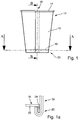
- the representation of the Fig. 1 shows a side view of a container according to the invention, which is designed here as a cup 10.
- the cup 10 has a frustoconical jacket 12 which is provided with a so-called lip curl 14 on its upper edge.
- the jacket 12 is wound from a flat segment, as it is for example in FIGS. 2 and 3 is shown. The longitudinal edges of this segment are placed on top of one another during winding, so that an overlap area 16 is formed.
- the jacket 12 has a frustoconical shape after winding.
- the cup 10 is provided with a closing element in the form of a base 18.
- the bottom 18 has an approximately pot-shaped design.
- the base 18 is formed from a, for example, circular disk-shaped paper segment, the edges of which are folded down by 90 ° or slightly more than 90 ° and thereby form a base collar 24 projecting approximately vertically downward from a base plate 22, see Fig. 1a .
- the lower end of the jacket 12 is turned over by 180 °.
- the jacket 12, which is turned around the base collar 24, and the base collar 24 are then first heated by means of hot air and then pressed together.
- the paper material of the base 18 and of the casing 12 is provided with a plastic coating, for example polyethylene, on at least one side.
- the thermoplastic plastic coating is heated and when the jacket 12 and base 18 are pressed, jacket 12 and base 18 are then sealed to one another in the area of the so-called frame 20.
- FIG. 11 shows a sectional view of the sectional plane BB of FIG Fig. 1 .
- the cutting plane BB is placed in the overlap region 16, in which the jacket 12 consists of two layers of material lying on top of one another.
- the base 18 has the base plate 22 and the base collar 24 which projects downwards approximately perpendicularly from the base plate 22.
- the lower end of the jacket 12 is wrapped around the base collar 24.
- two material layers of the flat segment from which the jacket 12 is formed lie one above the other on both the inside and the outside of the bottom collar 24.
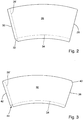
- Fig. 2 shows a plan view of a flat segment 26 for a cup 10 according to a first embodiment.
- the segment 26 is on a conical or frustoconical mandrel wound, so that the frustoconical shell 12 results.
- the segment 26 has a first side edge 28 and a second side edge 30.
- the side edge 30 goes to her in Fig. 2 lower end in a bevel 32 over.
- the bevel 32 serves to space the segment edge resting on the base collar 24 on the inside and the outside of the base collar 24 from one another in the circumferential direction.
- the jacket 26 is folded around the lower end of the base collar 24 approximately in the area of the dashed line 34.
- FIG. 3 shows a segment 36 for a cup according to the invention according to a further embodiment.
- a first side edge 38 has a bevel 40 at its upper end and a second side edge 42 is provided with a re-entrant corner 44 at its lower end.
- the re-entrant corner 44 serves to space the segment edge resting on the base collar 24 on the inside and the outside of the base collar 24 in the circumferential direction when the lower end of the jacket is turned over.
- the beveled end 40 of the first side edge 38 is used to ensure that the lip curl 14 can also be easily shaped in the overlapping area.
- the upper end of the casing 12 can also be turned over around a cover collar of a cover. This is done with containers according to the invention which are designed as cans. A cover would then be inserted exactly the other way around as the bottom 18 in the jacket, so that the cover collar protrudes upwards from a cover plate and the upper end of the jacket would then be folded around this cover collar by 180 ° and the cover collar and the upper folded-over end of the Mantle would then be pressed into a frame and sealed.
- the representation of the Fig. 4 shows a sectional view of the section plane AA in FIG Fig. 1 before pressing the frame 20.
- the section plane AA is shown in the overlap area 16.
- the jacket 12 is, see also Fig. 1a , wrapped around the end of the bottom collar 24 with its lower end.
- the second segment edge 30 rests on an outside of the bottom collar 24 and then runs through the bevel 32, not visible in FIG Fig. 4 , in the circumferential direction to the right. On the inside, the second segment edge 30 then rests on the inside of the floor collar 24 at a distance from the second segment edge 30 in the circumferential direction due to the bevel 32.
- the first segment edge 28 lies on the outside of the bottom collar 24 at a distance from the bottom collar 24 in the radial direction, and the first segment edge 28 is also at a distance from the bottom collar 24 on the inside of the bottom collar 24.
- the area of the segment which adjoins the first segment edge 28 has a stepped area 46, 48 both on the inside and on the outside of the bottom collar 24.
- This area 46 on the outside of the bottom collar 24 and also the area 48 on the inside of the bottom collar 24 are each arranged in the area of the second segment edge 30 and still belong to the overlap area.
- the overlap area 16 ends in Fig. 4 on the one hand at the first segment edge 28 and on the other hand at the second segment edge 30.
- an edge section of the overlap area includes the step-shaped area 46 and the cavity 50 in front of the second segment edge 30, in other words the edge section ends at the point or at the line, at which the step-shaped area 46 ends and the segment rests on the outside of the floor collar 24 again.
- a cavity 50 is located in the stepped region 46 in front of the second segment edge 30.
- This cavity 50 has an approximately triangular cross-section and is created by the step-shaped region 46.
- Fig. 4 shows the state of the frame 20 in the area of the overlap 16 before pressing and sealing.
- the cavity 50 is connected to the interior of the cup 10 before the pressing, since the second segment edge 30 extends into the interior of the cup 10.
- sealing material that is to say the melted PE coating of the material of the jacket 12 and / or of the base 18. If this does not succeed, the cavity 50 represents a potential leak point via which liquid can then get from the interior of the cup 10 into the area of the frame 20.
- Fig. 4 shows a conventional press ram 54 on the radially inner side of the frame 20.
- This conventional press ram 54 is radially outward, in Fig. 4 so moved down to crimp and seal the frame 20.
- a plurality of circular segment-shaped press punches 54 are provided, which are arranged on the inside of the frame 20 and then moved radially outward. Nevertheless, the liquid-tight design of the frame 20 is problematic.
- Fig. 5 shows a in the area of the frame 20 of the illustration of FIG Fig. 4 corresponding representation of the jacket 12 and the bottom collar 24. The jacket 12 and the bottom collar 24 are therefore not explained again.
- This press ram 56 has a radially outwardly protruding projection 58 which protrudes radially outward relative to the remaining press surface 60 of the press ram 56.
- This projection 58 is arranged and dimensioned in such a way that it applies an increased pressure to the overlap 16 in the edge section, i.e. in the area of the cavity 50 in front of the second segment edge 30 on the outside of the base collar 24. In this way, after the frame 20 has been pressed and sealed, it can be ensured that the cavity 50 is significantly smaller than in conventional cups and is in any case completely filled with sealing material.
- FIG. 6 The state after pressing the frame is shown in the illustration of Fig. 6 .
- the frame 20 is in the not yet pressed state Fig. 5 warmed, for example subjected to hot air from the underside.
- a radially outwardly directed pressing pressure is then exerted on the frame 20, which in FIG Fig. 6 is symbolized by the arrow 62.
- a pressing pressure directed outward in the radial direction is exerted over the entire circumference of the frame by means of the press ram 56 or a plurality of press rams 56.
- Fig. 6 shows the already fully pressed and sealed state of the frame 20. It can be clearly seen that the cavity 50 is on the outside in front of the inner segment edge 30 of the bottom collar 24 is completely filled with sealing material, which in Fig. 6 is shown in black.
- the frame 20 Due to the increased pressing pressure in the area of the projection 58, the frame 20 has a recess 66 on its inside.
- the dimensions of the recess 66 correspond approximately to the dimensions of the projection 58.
- the ram 56 and thus the pressing surface 60 generally have a height which corresponds to the height of the frame on the inside of the frame 20.
- the pressing surface 60 can also be designed in the form of one or more strips, see Figure 5a . These strips can then each have a protrusion 58 which protrudes in the radial direction and the function of the protrusion 58 of the ram 56 in FIG Fig. 6 met as this in Figure 5a is shown. If necessary, it can also be sufficient to provide only one of the strips with a projection.
- FIG. 7 shows the cup in the area of the frame 20 with the ram 56 in the already pressed state of FIG Fig. 6 .
- the ram 56 and the frame 20 are therefore not explained again.
- a counterpart 70 is arranged on the outside of the frame 20 opposite the ram 56.
- the counterpart 70 has a concave shape, the radius of this concave shape approximately corresponding to the outer radius of the frame 20. When the frame 20 is pressed, this counterpart 70 absorbs the pressing pressure exerted by the press ram 56.
- the representation of the Fig. 8 shows the arrangement of the Fig. 7 , wherein instead of the counterpart 70 a counterpart 72 is shown, which has a recess 74 on its side facing the frame 20.
- the recess 74 is approximately as wide as the overlap area 16 on the outside of the frame 20, which is shown in FIG Fig. 8 is down.
- the overlap area 16 can be received in the counterpart 72 through the recess 74 and the increased pressing pressure in the area of the arrow 62 can be concentrated on the area of the cavity 50.
- the recess 74 has rounded side edges so that damage to the outside of the frame 20 is avoided.
- the recess 74 has a depth which corresponds approximately to the material thickness of the segment 26 for producing the outer jacket 12. Thereby a secure pressing and sealing can be achieved in the area of the cavity 50 without the risk of the material of the jacket 12 being damaged in the area of the overlap 16 by excessive pressure.
- the representation of the Fig. 9 shows a further embodiment of a container according to the invention.
- the representation of the Fig. 9 represents one of the Fig. 4 corresponding partial sectional view, the cutting plane being the same as the cutting plane AA in FIG Fig. 1 was placed through the frame 20.
- the ram 56 has already been explained and has the projection 58.
- the coat 74 of the Fig. 9 formed from a segment, the second segment edge 30 of which is provided with a sealing strip 76.
- the sealing strip 76 consists of a sealable thermoplastic material, for example polyethylene.
- the sealing strip 76 is wrapped around the second segment edge 30 so that the sealing strip extends a little way along the overlap region 16 on both sides of the segment edge 30.
- additional thermoplastic material is available when the frame 20 is pressed in order to completely fill the cavity 50 in front of the inner segment edge 30, which rests on the outside of the bottom collar 24, with sealing material, in this case polyethylene.
- the provision of the sealing strip 76 thereby enables an even more reliable sealing of the frame 20 with respect to the interior of the container according to the invention.
- the sealing strip 76 can prevent the open cut edge on the segment edge 30 from coming into contact with liquid within the Container comes.
- the sealing strip 76 is therefore preferably used in cans made of paper material or paper-like material that are intended to be filled with liquid as cups over a longer period of time.
- the jacket 74 would not only be connected to the base collar 24 by means of the frame 20, but, as already explained at the beginning, would also be connected in a liquid-tight manner to a pot-shaped lid by means of a further frame.
- the inner segment edge 30 is then provided with the sealing strip 76 in order to achieve a particularly liquid-tight design of the frame in the area of the cover.
Landscapes
- Engineering & Computer Science (AREA)
- Mechanical Engineering (AREA)
- Making Paper Articles (AREA)
- Closing Of Containers (AREA)
- Closures For Containers (AREA)
Claims (15)
- Dispositif de fabrication de récipients en matériau de papier ou en matériau similaire au papier, dans lequel le récipient comprend une enveloppe (12) constituée d'un segment plan enroulé (26, 36), dont les arêtes de segment (28, 30 ; 38, 42) disposées sur les côtés longitudinaux se chevauchent et forment ainsi une région de chevauchement (16), et un élément de terminaison en forme de pot, à savoir un fond (18) en forme de pot et/ou un couvercle en forme de pot, dans lequel l'enveloppe (12) et l'élément de terminaison sont reliés l'un à l'autre de manière sensiblement étanche aux liquides au moyen d'un rebord (20), dans lequel au moins un poinçon de pressage (56) est prévu pour le pressage et le scellage du rebord (20), lequel poinçon soumet le rebord (20) à une pression de pressage orientée sensiblement radialement, caractérisé en ce que le poinçon de pressage (56) comprend, dans une partie du poinçon de pressage (56) prévue pour la sollicitation d'une partie de bord de la région de chevauchement (16) de l'enveloppe (12) sur le rebord (20), une saillie (58) faisant saillie dans la direction radiale, dans lequel la partie de bord de la région de chevauchement (16) s'étend, au moins à partir de l'arête de segment inférieure ou recouverte (30 ; 42) qui est recouverte par le segment (26 ; 36) reposant sur l'arête de segment (30 ; 42), jusqu'à une région dans laquelle le segment plan (26 ; 36) qui repose sur l'arête de segment inférieure (30 ; 42) est disposé à nouveau à la même hauteur que l'arête de segment inférieure ou recouverte (30 ; 42).
- Dispositif selon la revendication 1, caractérisé en ce que la saillie (58) s'étend, dans la direction périphérique, sur une largeur qui représente entre 0,25 fois et 0,75 fois, en particulier 0,5 fois, la largeur de la région de chevauchement (16) dans la direction périphérique.
- Dispositif selon la revendication 1 ou 2, caractérisé en ce que la saillie (58) est disposée par rapport à la région de chevauchement (16) dans la direction périphérique de telle sorte que seulement l'une des arêtes de segment (30 ; 42) de l'enveloppe (12) dans la région de chevauchement (16) est soumise à une pression de pressage accrue.
- Dispositif selon la revendication 3, caractérisé en ce que la saillie (58) est disposée symétriquement par rapport à un bord de la région de chevauchement (16).
- Dispositif selon la revendication 4, caractérisé en ce que la saillie (58) est disposée symétriquement par rapport à l'arête de segment (30 ; 42) de la région de chevauchement (16) s'appuyant sur le côté extérieur de l'élément de terminaison.
- Dispositif selon au moins l'une des revendications précédentes, caractérisé en ce qu'une pièce conjuguée (72) est opposée au poinçon de pressage (56), le rebord (20) étant reçu entre la pièce conjuguée (72) et le poinçon de pressage (56), et la pièce conjuguée (72) comprenant un évidement (74) dans la région dans laquelle la région de chevauchement (16) vient se placer.
- Dispositif selon la revendication 6, caractérisé en ce qu'une largeur de l'évidement (74) dans la direction périphérique représente 0,5 fois à 1,5 fois la largeur de la région de chevauchement (16).
- Dispositif selon la revendication 6 ou 7, caractérisé en ce qu'une profondeur de l'évidement (74) représente 0,75 fois à 1,25 fois, en particulier 1 fois, l'épaisseur du segment plan (26 ; 36) pour l'enveloppe (12).
- Procédé de fabrication d'un récipient en matériau de papier ou en matériau similaire au papier, comprenant les étapes suivantes : enroulement d'un segment plan (26, 36) de manière à former une enveloppe (12), de telle sorte que les arêtes de segment (28, 30 ; 38, 42) disposées sur les côtés longitudinaux se chevauchent et forment ainsi une région de chevauchement (16), liaison d'un élément de terminaison en forme de pot, à savoir d'un fond (18) en forme de pot et/ou d'un couvercle en forme de pot, à l'enveloppe (12) au moyen d'un rebord (20), de telle sorte que l'enveloppe (12) et l'élément de terminaison soient reliés l'un à l'autre de manière sensiblement étanche aux liquides, pressage et scellage de l'enveloppe (12) et de l'élément de terminaison dans la région du rebord (20) à l'aide d'au moins un poinçon de pressage (56), de telle sorte que le rebord (20) soit soumis à une pression de pressage orientée sensiblement radialement, caractérisé par la sollicitation d'une partie de bord de la région de chevauchement (16) de l'enveloppe (12) dans la région du rebord (20) par une pression de pressage accrue par comparaison avec le reste du rebord (20), la partie de bord de la région de chevauchement (16) s'étendant, au moins à partir de l'arête de segment inférieure ou recouverte (30 ; 42) qui est recouverte par le segment (26 ; 36) reposant sur l'arête de segment (30 ; 42), jusqu'à une région dans laquelle le segment plan (26 ; 36) qui repose sur l'arête de segment inférieure (30 ; 42) est disposé à nouveau à la même hauteur que l'arête de segment inférieure ou recouverte (30 ; 42).
- Procédé selon la revendication 9, caractérisé par l'application de la pression de pressage accrue au moyen d'une saillie (58), faisant saillie dans la direction radiale, sur le poinçon de pressage (56).
- Procédé selon la revendication 9 ou 10, caractérisé par la sollicitation, par la pression de pressage accrue, d'une région sur le côté intérieur du rebord (20), laquelle région est opposée à l'arête de segment intérieure (30 ; 42) de l'enveloppe (12), laquelle arête repose sur le côté extérieur de l'élément de terminaison.
- Procédé selon la revendication 11, caractérisé en ce que la région qui est soumise à la pression de pressage accrue est disposée symétriquement par rapport à la partie de bord de la région de chevauchement (16) sur laquelle est disposée l'arête de segment intérieure (30 ; 42) de l'enveloppe (12) qui repose sur le côté extérieur de l'élément de terminaison.
- Procédé selon l'une des revendications 9 à 12, caractérisé par la sollicitation, par la pression de pressage accrue, d'une région du rebord (20) dont la largeur représente 0,25 fois à 0,75 fois, en particulier 0,5 fois, la largeur de la région de chevauchement (16).
- Récipient en plusieurs parties en matériau de papier ou en matériau similaire au papier, comprenant une enveloppe (12) qui est formée à partir d'un segment plan enroulé (26, 36), dont les arêtes de segment latérales (28, 30 ; 38, 42) sont disposées à l'état enroulé dans une région de chevauchement (16), et comprenant un élément de terminaison en forme de pot, à savoir un fond (18) en forme de pot et/ou un couvercle en forme de pot, dans lequel l'enveloppe (12) et l'élément de terminaison sont reliés l'un à l'autre de manière sensiblement étanche aux liquides au moyen d'un rebord (20), dans lequel, dans la région du rebord (20), l'enveloppe (12) et l'élément de terminaison sont pressés et scellés l'un avec l'autre, caractérisé en ce qu'au niveau d'un bord de la région de chevauchement (16), un espace intermédiaire (50) est rempli complètement d'un matériau de scellage, lequel espace intermédiaire est formé entre l'arête de segment (30 ; 42) reposant sur le côté extérieur de l'élément de terminaison et la partie du segment (26 ; 36) de l'enveloppe (12) reposant sur l'arête de segment (30 ; 42), et en ce qu'un évidement enfoncé (66) est prévu sur le côté intérieur du rebord (20) dans la région opposée à l'arête de segment (30 ; 42) qui repose sur le côté extérieur de l'élément de terminaison, l'évidement (66) étant formé par sollicitation d'une partie de bord de la région de chevauchement (16) de l'enveloppe (12) dans la région du rebord (20) par une pression de pressage accrue par comparaison avec le reste du rebord (20) et la partie de bord de la région de chevauchement (16) s'étendant, au moins à partir de l'arête de segment inférieure ou recouverte (30 ; 42) qui est recouverte par le segment (26 ; 36) reposant sur l'arête de segment (30 ; 42), jusqu'à une région dans laquelle le segment plan (26 ; 36) qui repose sur l'arête de segment inférieure (30 ; 42) est disposé à nouveau à la même hauteur que l'arête de segment inférieure ou recouverte (30 ; 42).
- Récipient selon la revendication 14, caractérisé en ce qu'une largeur de l'évidement (66) dans la direction périphérique représente entre 0,25 fois et 0,75 fois, en particulier 0,5 fois, la largeur de la région de chevauchement (16).
Applications Claiming Priority (1)
| Application Number | Priority Date | Filing Date | Title |
|---|---|---|---|
| DE102017201595.0A DE102017201595A1 (de) | 2017-02-01 | 2017-02-01 | Vorrichtung und Verfahren zum Herstellen von Behältern aus Papiermaterial oder papierähnlichem Material und Behälter |
Publications (2)
| Publication Number | Publication Date |
|---|---|
| EP3360676A1 EP3360676A1 (fr) | 2018-08-15 |
| EP3360676B1 true EP3360676B1 (fr) | 2020-11-04 |
Family
ID=61027435
Family Applications (1)
| Application Number | Title | Priority Date | Filing Date |
|---|---|---|---|
| EP18152135.2A Active EP3360676B1 (fr) | 2017-02-01 | 2018-01-17 | Dispositif et procédé de fabrication de récipients en matériau de papier ou en matériau similaire au papier et récipient |
Country Status (5)
| Country | Link |
|---|---|
| US (1) | US11104472B2 (fr) |
| EP (1) | EP3360676B1 (fr) |
| KR (1) | KR102489639B1 (fr) |
| CN (1) | CN108382681B (fr) |
| DE (1) | DE102017201595A1 (fr) |
Families Citing this family (4)
| Publication number | Priority date | Publication date | Assignee | Title |
|---|---|---|---|---|
| CA2969630A1 (fr) | 2016-06-03 | 2017-12-03 | H. J. Paul Langen | Methode et appareil de faconnage de contenants |
| US11780199B2 (en) | 2016-06-03 | 2023-10-10 | Lancan Systems Inc. | Method and apparatus for forming containers |
| US11772352B2 (en) * | 2020-04-20 | 2023-10-03 | H. J. Paul Langen | Method and apparatus for forming containers |
| CN113619191B (zh) * | 2021-07-04 | 2023-06-13 | 浙江新德宝机械有限公司 | 纸容器成型机 |
Family Cites Families (29)
| Publication number | Priority date | Publication date | Assignee | Title |
|---|---|---|---|---|
| US2029827A (en) * | 1922-02-02 | 1936-02-04 | Majer Christian | Machine for continuously inserting bottoms and lids in finished vessel walls of paper, cardboard, and the like |
| US3063347A (en) * | 1960-03-31 | 1962-11-13 | Hudson Pulp & Paper Corp | Cup making machine |
| US3343465A (en) * | 1962-10-31 | 1967-09-26 | Standard Packaging Corp | Cup-making machine |
| US3438824A (en) * | 1965-05-14 | 1969-04-15 | Cavitron Corp | Method and apparatus for joining a closure to a container by high frequency radial vibrations |
| US4100842A (en) * | 1977-05-18 | 1978-07-18 | Phillips Petroleum Company | Apparatus for forming a container |
| DE3240811C2 (de) | 1982-11-05 | 1986-03-20 | Maschinenfabrik Rissen Gmbh, 2000 Hamburg | Verfahren zum Verbinden eines Mantelteils eines Becherbehälters mit einem Bodenteil |
| US4571233A (en) * | 1984-01-06 | 1986-02-18 | Paper Machinery Corporation | Paper container bottom expander |
| DE3903980A1 (de) * | 1989-02-10 | 1990-08-16 | Thorsten Seufert | Fuer den versand in leerem zustand vorgesehener verpackungsbehaelter und verfahren zu seiner herstellung |
| US5035106A (en) * | 1989-12-12 | 1991-07-30 | Ccl Industries | Method of sealing a valve to an aerosol container |
| US5830305A (en) * | 1992-08-11 | 1998-11-03 | E. Khashoggi Industries, Llc | Methods of molding articles having an inorganically filled organic polymer matrix |
| DE4406886A1 (de) | 1994-03-03 | 1995-09-07 | Rheinische Wellpappenfabrik | Aufnahmeschale sowie Verfahren und Vorrichtung zu ihrer Herstellung |
| US5624367A (en) * | 1994-09-15 | 1997-04-29 | Paper Machinery Corporation | Bottom blank maker workstation for a cup making machine |
| US5569143A (en) * | 1994-09-15 | 1996-10-29 | Paper Machinery Corporation | Cup bottom finishing station for a cup making machine |
| US5556364A (en) * | 1994-09-22 | 1996-09-17 | Paper Machinery Corporation | Cup bottom incurl workstation for a cup making machine |
| KR0142358B1 (ko) * | 1995-04-26 | 1998-07-15 | 이재정 | 금속용기의 벌지성형방법 및 장치 |
| CN101531260B (zh) | 2000-12-14 | 2011-01-26 | 大日本印刷株式会社 | 微波炉用纸杯 |
| DE20319691U1 (de) | 2003-12-18 | 2005-05-04 | Seda S.P.A., Arzano | Zuschnitt für einen Behälter und aus dem Zuschnitt hergestellter Behälter |
| US7926535B2 (en) * | 2004-05-18 | 2011-04-19 | Seda S.P.A. | Tool |
| DE202005019396U1 (de) * | 2005-12-12 | 2007-04-19 | Seda S.P.A., Arzano | Werkzeug |
| DE102006057531B4 (de) | 2005-12-12 | 2016-02-18 | Seda International Packaging Group Spa | Werkzeug |
| US7686753B2 (en) * | 2006-07-27 | 2010-03-30 | Paper Machinery Corporation | Bottom finishing station components for a cup making machine |
| US8336186B2 (en) * | 2008-01-08 | 2012-12-25 | Packaging Technologies, Inc. | Apparatus for placing and attaching formed filters into brewing cups |
| DE102008005403A1 (de) | 2008-01-21 | 2009-07-23 | Ptm Packaging Tools Machinery Pte.Ltd. | Becher aus einem Papiermaterial |
| DE102009055986A1 (de) * | 2008-12-22 | 2010-06-24 | Michael Hörauf Maschinenfabrik GmbH & Co. KG | Vorrichtung zum Auftragen von Klebstoff sowie Maschine und Verfahren zum Herstellen von Papierbechern |
| JP6023426B2 (ja) | 2009-06-23 | 2016-11-09 | 凸版印刷株式会社 | レトルトカップ |
| MX2013001728A (es) | 2010-08-25 | 2013-05-30 | Dixie Consumer Products Llc | Junta de sellado de copa de papel mejorada |
| CN203254705U (zh) | 2013-05-28 | 2013-10-30 | 嘉兴雁荡包装有限公司 | 一种纸杯杯底成形机用压模装置 |
| DE102013107429B3 (de) * | 2013-07-12 | 2014-06-05 | Sig Technology Ag | Vorrichtung und Verfahren zum flüssigkeitsdichten Versiegeln von zwei sich teilweise überlappenden Verpackungsteilen und damit/danach hergestellter Behälter |
| DE102014210960A1 (de) | 2014-06-06 | 2015-12-31 | Michael Hörauf Maschinenfabrik Gmbh U. Co. Kg | Verfahren zum Herstellen eines Bechers |
-
2017
- 2017-02-01 DE DE102017201595.0A patent/DE102017201595A1/de not_active Withdrawn
-
2018
- 2018-01-17 EP EP18152135.2A patent/EP3360676B1/fr active Active
- 2018-01-23 US US15/877,912 patent/US11104472B2/en active Active
- 2018-02-01 CN CN201810102141.2A patent/CN108382681B/zh active Active
- 2018-02-01 KR KR1020180013049A patent/KR102489639B1/ko active Active
Non-Patent Citations (1)
| Title |
|---|
| None * |
Also Published As
| Publication number | Publication date |
|---|---|
| EP3360676A1 (fr) | 2018-08-15 |
| KR102489639B1 (ko) | 2023-01-17 |
| KR20180089874A (ko) | 2018-08-09 |
| CN108382681B (zh) | 2021-08-17 |
| DE102017201595A1 (de) | 2018-08-02 |
| US11104472B2 (en) | 2021-08-31 |
| CN108382681A (zh) | 2018-08-10 |
| US20180215497A1 (en) | 2018-08-02 |
Similar Documents
| Publication | Publication Date | Title |
|---|---|---|
| EP3360676B1 (fr) | Dispositif et procédé de fabrication de récipients en matériau de papier ou en matériau similaire au papier et récipient | |
| DE2700230C2 (de) | Becherförmiger Behälter | |
| EP2128041B1 (fr) | Enveloppe extérieure pour un gobelet à double paroi et son procédé de fabrication | |
| AT15830U1 (de) | Eine Kapsel, ein System zur Zubereitung eines trinkbaren Getränks aus einer solchen Kapsel und Verwendung einer solchen Kapsel in einer Getränkezubereitungsvorrichtung | |
| DE102016006033A1 (de) | Eine Kapsel, ein System zur Zubereitung eines trinkbaren Getränks aus einer solchen Kapsel und Verwendung einer solchen Kapsel in einer Getränkezubereitungsvorrichtung | |
| DE202016106169U1 (de) | Kapsel und System zur Zubereitung eines trinkbaren Getränks aus einer solchen Kapsel | |
| AT517118A2 (de) | Eine Kapsel, ein System zur Zubereitung eines trinkbaren Getränks aus einer solchen Kapsel und Verwendung einer solchen Kapsel in einer Getränkezubereitungsvorrichtung | |
| DE3048996A1 (de) | "behaelter sowie verfahren und vorrichtung zu seiner herstellung" | |
| EP2986514A1 (fr) | Capsule de portion pour préparer un produit d'infusion | |
| EP3924271B1 (fr) | Système servant à préparer une boisson à partir d'une capsule | |
| EP2952340B1 (fr) | Procédé destiné à la fabrication d'un gobelet | |
| EP2540636B1 (fr) | Gobelet en papier et procédé et dispositif de fabrication d'un gobelet en papier | |
| DE4411924A1 (de) | Behälter | |
| EP0819086A1 (fr) | Boite munie d'une membrane de fermeture en feuille, ainsi que procede, dispositif et feuille pour la fabrication de cette boite | |
| DE69026279T2 (de) | Herstellungsverfahren einer verbesserten abdichtung an deckeln von aerosolbehältern | |
| EP2804706B1 (fr) | Procédé de fabrication d'une boîte métallique à opercule déchirable et boîte à opercule déchirable | |
| EP2674370B1 (fr) | Couvercle en plusieurs parties en papier et procédé de fabrication d'un couvercle | |
| EP3672774B1 (fr) | Procédé et dispositif pour appliquer une masse d'étanchéité sur le fond et le côté intérieur d'une paroi annulaire d'un couvercle de récipient | |
| DE2246779A1 (de) | Dose mit abdeckmembran | |
| DE2659521A1 (de) | Behaelter und verfahren zu seiner herstellung | |
| EP0676336A2 (fr) | Procédé de recouvrement du bord coupant d'une ouverture de récipient au moyen d'un recouvrement de protection | |
| EP3829992B1 (fr) | Emballage de tube | |
| EP4469364B1 (fr) | Emballage constitué d'un matériau en feuille métallique avec couvercle en feuille déchirable et ensemble de matériaux et procédé de production associé | |
| EP0700838B1 (fr) | Boíte avec fermeture sous forme de films et procédé pour sa fabrication | |
| DE1461779C3 (de) | Verfahren und Vorrichtung zum dichten Verbinden von Behälter und Deckel |
Legal Events
| Date | Code | Title | Description |
|---|---|---|---|
| PUAI | Public reference made under article 153(3) epc to a published international application that has entered the european phase |
Free format text: ORIGINAL CODE: 0009012 |
|
| STAA | Information on the status of an ep patent application or granted ep patent |
Free format text: STATUS: THE APPLICATION HAS BEEN PUBLISHED |
|
| AK | Designated contracting states |
Kind code of ref document: A1 Designated state(s): AL AT BE BG CH CY CZ DE DK EE ES FI FR GB GR HR HU IE IS IT LI LT LU LV MC MK MT NL NO PL PT RO RS SE SI SK SM TR |
|
| AX | Request for extension of the european patent |
Extension state: BA ME |
|
| STAA | Information on the status of an ep patent application or granted ep patent |
Free format text: STATUS: REQUEST FOR EXAMINATION WAS MADE |
|
| 17P | Request for examination filed |
Effective date: 20190206 |
|
| RBV | Designated contracting states (corrected) |
Designated state(s): AL AT BE BG CH CY CZ DE DK EE ES FI FR GB GR HR HU IE IS IT LI LT LU LV MC MK MT NL NO PL PT RO RS SE SI SK SM TR |
|
| GRAP | Despatch of communication of intention to grant a patent |
Free format text: ORIGINAL CODE: EPIDOSNIGR1 |
|
| STAA | Information on the status of an ep patent application or granted ep patent |
Free format text: STATUS: GRANT OF PATENT IS INTENDED |
|
| RIC1 | Information provided on ipc code assigned before grant |
Ipc: B31B 50/64 20170101ALI20200429BHEP Ipc: B31F 1/00 20060101ALI20200429BHEP Ipc: B31B 50/60 20170101AFI20200429BHEP Ipc: B31C 7/06 20060101ALI20200429BHEP |
|
| INTG | Intention to grant announced |
Effective date: 20200527 |
|
| GRAS | Grant fee paid |
Free format text: ORIGINAL CODE: EPIDOSNIGR3 |
|
| GRAA | (expected) grant |
Free format text: ORIGINAL CODE: 0009210 |
|
| STAA | Information on the status of an ep patent application or granted ep patent |
Free format text: STATUS: THE PATENT HAS BEEN GRANTED |
|
| AK | Designated contracting states |
Kind code of ref document: B1 Designated state(s): AL AT BE BG CH CY CZ DE DK EE ES FI FR GB GR HR HU IE IS IT LI LT LU LV MC MK MT NL NO PL PT RO RS SE SI SK SM TR |
|
| REG | Reference to a national code |
Ref country code: GB Ref legal event code: FG4D Free format text: NOT ENGLISH |
|
| REG | Reference to a national code |
Ref country code: CH Ref legal event code: EP |
|
| REG | Reference to a national code |
Ref country code: AT Ref legal event code: REF Ref document number: 1330281 Country of ref document: AT Kind code of ref document: T Effective date: 20201115 |
|
| REG | Reference to a national code |
Ref country code: IE Ref legal event code: FG4D Free format text: LANGUAGE OF EP DOCUMENT: GERMAN |
|
| REG | Reference to a national code |
Ref country code: DE Ref legal event code: R096 Ref document number: 502018002869 Country of ref document: DE |
|
| REG | Reference to a national code |
Ref country code: NL Ref legal event code: MP Effective date: 20201104 |
|
| PG25 | Lapsed in a contracting state [announced via postgrant information from national office to epo] |
Ref country code: FI Free format text: LAPSE BECAUSE OF FAILURE TO SUBMIT A TRANSLATION OF THE DESCRIPTION OR TO PAY THE FEE WITHIN THE PRESCRIBED TIME-LIMIT Effective date: 20201104 Ref country code: RS Free format text: LAPSE BECAUSE OF FAILURE TO SUBMIT A TRANSLATION OF THE DESCRIPTION OR TO PAY THE FEE WITHIN THE PRESCRIBED TIME-LIMIT Effective date: 20201104 Ref country code: PT Free format text: LAPSE BECAUSE OF FAILURE TO SUBMIT A TRANSLATION OF THE DESCRIPTION OR TO PAY THE FEE WITHIN THE PRESCRIBED TIME-LIMIT Effective date: 20210304 Ref country code: GR Free format text: LAPSE BECAUSE OF FAILURE TO SUBMIT A TRANSLATION OF THE DESCRIPTION OR TO PAY THE FEE WITHIN THE PRESCRIBED TIME-LIMIT Effective date: 20210205 Ref country code: NO Free format text: LAPSE BECAUSE OF FAILURE TO SUBMIT A TRANSLATION OF THE DESCRIPTION OR TO PAY THE FEE WITHIN THE PRESCRIBED TIME-LIMIT Effective date: 20210204 |
|
| PG25 | Lapsed in a contracting state [announced via postgrant information from national office to epo] |
Ref country code: BG Free format text: LAPSE BECAUSE OF FAILURE TO SUBMIT A TRANSLATION OF THE DESCRIPTION OR TO PAY THE FEE WITHIN THE PRESCRIBED TIME-LIMIT Effective date: 20210204 Ref country code: PL Free format text: LAPSE BECAUSE OF FAILURE TO SUBMIT A TRANSLATION OF THE DESCRIPTION OR TO PAY THE FEE WITHIN THE PRESCRIBED TIME-LIMIT Effective date: 20201104 Ref country code: IS Free format text: LAPSE BECAUSE OF FAILURE TO SUBMIT A TRANSLATION OF THE DESCRIPTION OR TO PAY THE FEE WITHIN THE PRESCRIBED TIME-LIMIT Effective date: 20210304 Ref country code: LV Free format text: LAPSE BECAUSE OF FAILURE TO SUBMIT A TRANSLATION OF THE DESCRIPTION OR TO PAY THE FEE WITHIN THE PRESCRIBED TIME-LIMIT Effective date: 20201104 Ref country code: SE Free format text: LAPSE BECAUSE OF FAILURE TO SUBMIT A TRANSLATION OF THE DESCRIPTION OR TO PAY THE FEE WITHIN THE PRESCRIBED TIME-LIMIT Effective date: 20201104 Ref country code: ES Free format text: LAPSE BECAUSE OF FAILURE TO SUBMIT A TRANSLATION OF THE DESCRIPTION OR TO PAY THE FEE WITHIN THE PRESCRIBED TIME-LIMIT Effective date: 20201104 |
|
| REG | Reference to a national code |
Ref country code: LT Ref legal event code: MG9D |
|
| PG25 | Lapsed in a contracting state [announced via postgrant information from national office to epo] |
Ref country code: HR Free format text: LAPSE BECAUSE OF FAILURE TO SUBMIT A TRANSLATION OF THE DESCRIPTION OR TO PAY THE FEE WITHIN THE PRESCRIBED TIME-LIMIT Effective date: 20201104 |
|
| PG25 | Lapsed in a contracting state [announced via postgrant information from national office to epo] |
Ref country code: RO Free format text: LAPSE BECAUSE OF FAILURE TO SUBMIT A TRANSLATION OF THE DESCRIPTION OR TO PAY THE FEE WITHIN THE PRESCRIBED TIME-LIMIT Effective date: 20201104 Ref country code: SK Free format text: LAPSE BECAUSE OF FAILURE TO SUBMIT A TRANSLATION OF THE DESCRIPTION OR TO PAY THE FEE WITHIN THE PRESCRIBED TIME-LIMIT Effective date: 20201104 Ref country code: SM Free format text: LAPSE BECAUSE OF FAILURE TO SUBMIT A TRANSLATION OF THE DESCRIPTION OR TO PAY THE FEE WITHIN THE PRESCRIBED TIME-LIMIT Effective date: 20201104 Ref country code: CZ Free format text: LAPSE BECAUSE OF FAILURE TO SUBMIT A TRANSLATION OF THE DESCRIPTION OR TO PAY THE FEE WITHIN THE PRESCRIBED TIME-LIMIT Effective date: 20201104 Ref country code: EE Free format text: LAPSE BECAUSE OF FAILURE TO SUBMIT A TRANSLATION OF THE DESCRIPTION OR TO PAY THE FEE WITHIN THE PRESCRIBED TIME-LIMIT Effective date: 20201104 Ref country code: LT Free format text: LAPSE BECAUSE OF FAILURE TO SUBMIT A TRANSLATION OF THE DESCRIPTION OR TO PAY THE FEE WITHIN THE PRESCRIBED TIME-LIMIT Effective date: 20201104 |
|
| REG | Reference to a national code |
Ref country code: DE Ref legal event code: R097 Ref document number: 502018002869 Country of ref document: DE |
|
| PG25 | Lapsed in a contracting state [announced via postgrant information from national office to epo] |
Ref country code: MC Free format text: LAPSE BECAUSE OF FAILURE TO SUBMIT A TRANSLATION OF THE DESCRIPTION OR TO PAY THE FEE WITHIN THE PRESCRIBED TIME-LIMIT Effective date: 20201104 Ref country code: DK Free format text: LAPSE BECAUSE OF FAILURE TO SUBMIT A TRANSLATION OF THE DESCRIPTION OR TO PAY THE FEE WITHIN THE PRESCRIBED TIME-LIMIT Effective date: 20201104 |
|
| REG | Reference to a national code |
Ref country code: CH Ref legal event code: PL |
|
| PLBE | No opposition filed within time limit |
Free format text: ORIGINAL CODE: 0009261 |
|
| STAA | Information on the status of an ep patent application or granted ep patent |
Free format text: STATUS: NO OPPOSITION FILED WITHIN TIME LIMIT |
|
| PG25 | Lapsed in a contracting state [announced via postgrant information from national office to epo] |
Ref country code: LU Free format text: LAPSE BECAUSE OF NON-PAYMENT OF DUE FEES Effective date: 20210117 |
|
| REG | Reference to a national code |
Ref country code: BE Ref legal event code: MM Effective date: 20210131 |
|
| 26N | No opposition filed |
Effective date: 20210805 |
|
| PG25 | Lapsed in a contracting state [announced via postgrant information from national office to epo] |
Ref country code: NL Free format text: LAPSE BECAUSE OF FAILURE TO SUBMIT A TRANSLATION OF THE DESCRIPTION OR TO PAY THE FEE WITHIN THE PRESCRIBED TIME-LIMIT Effective date: 20201104 Ref country code: AL Free format text: LAPSE BECAUSE OF FAILURE TO SUBMIT A TRANSLATION OF THE DESCRIPTION OR TO PAY THE FEE WITHIN THE PRESCRIBED TIME-LIMIT Effective date: 20201104 Ref country code: IT Free format text: LAPSE BECAUSE OF FAILURE TO SUBMIT A TRANSLATION OF THE DESCRIPTION OR TO PAY THE FEE WITHIN THE PRESCRIBED TIME-LIMIT Effective date: 20201104 |
|
| PG25 | Lapsed in a contracting state [announced via postgrant information from national office to epo] |
Ref country code: SI Free format text: LAPSE BECAUSE OF FAILURE TO SUBMIT A TRANSLATION OF THE DESCRIPTION OR TO PAY THE FEE WITHIN THE PRESCRIBED TIME-LIMIT Effective date: 20201104 Ref country code: CH Free format text: LAPSE BECAUSE OF NON-PAYMENT OF DUE FEES Effective date: 20210131 Ref country code: LI Free format text: LAPSE BECAUSE OF NON-PAYMENT OF DUE FEES Effective date: 20210131 |
|
| PG25 | Lapsed in a contracting state [announced via postgrant information from national office to epo] |
Ref country code: IE Free format text: LAPSE BECAUSE OF NON-PAYMENT OF DUE FEES Effective date: 20210117 |
|
| PG25 | Lapsed in a contracting state [announced via postgrant information from national office to epo] |
Ref country code: IS Free format text: LAPSE BECAUSE OF FAILURE TO SUBMIT A TRANSLATION OF THE DESCRIPTION OR TO PAY THE FEE WITHIN THE PRESCRIBED TIME-LIMIT Effective date: 20210304 |
|
| PG25 | Lapsed in a contracting state [announced via postgrant information from national office to epo] |
Ref country code: BE Free format text: LAPSE BECAUSE OF NON-PAYMENT OF DUE FEES Effective date: 20210131 |
|
| PG25 | Lapsed in a contracting state [announced via postgrant information from national office to epo] |
Ref country code: CY Free format text: LAPSE BECAUSE OF FAILURE TO SUBMIT A TRANSLATION OF THE DESCRIPTION OR TO PAY THE FEE WITHIN THE PRESCRIBED TIME-LIMIT Effective date: 20201104 |
|
| PG25 | Lapsed in a contracting state [announced via postgrant information from national office to epo] |
Ref country code: HU Free format text: LAPSE BECAUSE OF FAILURE TO SUBMIT A TRANSLATION OF THE DESCRIPTION OR TO PAY THE FEE WITHIN THE PRESCRIBED TIME-LIMIT; INVALID AB INITIO Effective date: 20180117 |
|
| REG | Reference to a national code |
Ref country code: AT Ref legal event code: MM01 Ref document number: 1330281 Country of ref document: AT Kind code of ref document: T Effective date: 20230117 |
|
| PG25 | Lapsed in a contracting state [announced via postgrant information from national office to epo] |
Ref country code: AT Free format text: LAPSE BECAUSE OF NON-PAYMENT OF DUE FEES Effective date: 20230117 |
|
| PG25 | Lapsed in a contracting state [announced via postgrant information from national office to epo] |
Ref country code: MK Free format text: LAPSE BECAUSE OF FAILURE TO SUBMIT A TRANSLATION OF THE DESCRIPTION OR TO PAY THE FEE WITHIN THE PRESCRIBED TIME-LIMIT Effective date: 20201104 Ref country code: AT Free format text: LAPSE BECAUSE OF NON-PAYMENT OF DUE FEES Effective date: 20230117 |
|
| PG25 | Lapsed in a contracting state [announced via postgrant information from national office to epo] |
Ref country code: MT Free format text: LAPSE BECAUSE OF FAILURE TO SUBMIT A TRANSLATION OF THE DESCRIPTION OR TO PAY THE FEE WITHIN THE PRESCRIBED TIME-LIMIT Effective date: 20201104 |
|
| PG25 | Lapsed in a contracting state [announced via postgrant information from national office to epo] |
Ref country code: TR Free format text: LAPSE BECAUSE OF FAILURE TO SUBMIT A TRANSLATION OF THE DESCRIPTION OR TO PAY THE FEE WITHIN THE PRESCRIBED TIME-LIMIT Effective date: 20201104 |
|
| PGFP | Annual fee paid to national office [announced via postgrant information from national office to epo] |
Ref country code: GB Payment date: 20260122 Year of fee payment: 9 |
|
| PGFP | Annual fee paid to national office [announced via postgrant information from national office to epo] |
Ref country code: DE Payment date: 20260127 Year of fee payment: 9 |
|
| PGFP | Annual fee paid to national office [announced via postgrant information from national office to epo] |
Ref country code: AT Payment date: 20260410 Year of fee payment: 5 |
|
| PGFP | Annual fee paid to national office [announced via postgrant information from national office to epo] |
Ref country code: FR Payment date: 20260123 Year of fee payment: 9 |