EP3360700B1 - Pneumatique et plot - Google Patents
Pneumatique et plot Download PDFInfo
- Publication number
- EP3360700B1 EP3360700B1 EP16853470.9A EP16853470A EP3360700B1 EP 3360700 B1 EP3360700 B1 EP 3360700B1 EP 16853470 A EP16853470 A EP 16853470A EP 3360700 B1 EP3360700 B1 EP 3360700B1
- Authority
- EP
- European Patent Office
- Prior art keywords
- end surface
- pair
- symmetry
- recessed portions
- axis
- Prior art date
- Legal status (The legal status is an assumption and is not a legal conclusion. Google has not performed a legal analysis and makes no representation as to the accuracy of the status listed.)
- Active
Links
Images


Classifications
-
- B—PERFORMING OPERATIONS; TRANSPORTING
- B60—VEHICLES IN GENERAL
- B60C—VEHICLE TYRES; TYRE INFLATION; TYRE CHANGING; CONNECTING VALVES TO INFLATABLE ELASTIC BODIES IN GENERAL; DEVICES OR ARRANGEMENTS RELATED TO TYRES
- B60C11/00—Tyre tread bands; Tread patterns; Anti-skid inserts
- B60C11/14—Anti-skid inserts, e.g. vulcanised into the tread band
- B60C11/16—Anti-skid inserts, e.g. vulcanised into the tread band of plug form, e.g. made from metal, textile
- B60C11/1625—Arrangements thereof in the tread patterns, e.g. irregular
-
- B—PERFORMING OPERATIONS; TRANSPORTING
- B60—VEHICLES IN GENERAL
- B60C—VEHICLE TYRES; TYRE INFLATION; TYRE CHANGING; CONNECTING VALVES TO INFLATABLE ELASTIC BODIES IN GENERAL; DEVICES OR ARRANGEMENTS RELATED TO TYRES
- B60C1/00—Tyres characterised by the chemical composition or the physical arrangement or mixture of the composition
- B60C1/0016—Compositions of the tread
-
- B—PERFORMING OPERATIONS; TRANSPORTING
- B60—VEHICLES IN GENERAL
- B60C—VEHICLE TYRES; TYRE INFLATION; TYRE CHANGING; CONNECTING VALVES TO INFLATABLE ELASTIC BODIES IN GENERAL; DEVICES OR ARRANGEMENTS RELATED TO TYRES
- B60C11/00—Tyre tread bands; Tread patterns; Anti-skid inserts
- B60C11/03—Tread patterns
- B60C11/032—Patterns comprising isolated recesses
-
- B—PERFORMING OPERATIONS; TRANSPORTING
- B60—VEHICLES IN GENERAL
- B60C—VEHICLE TYRES; TYRE INFLATION; TYRE CHANGING; CONNECTING VALVES TO INFLATABLE ELASTIC BODIES IN GENERAL; DEVICES OR ARRANGEMENTS RELATED TO TYRES
- B60C11/00—Tyre tread bands; Tread patterns; Anti-skid inserts
- B60C11/03—Tread patterns
- B60C11/12—Tread patterns characterised by the use of narrow slits or incisions, e.g. sipes
- B60C11/1236—Tread patterns characterised by the use of narrow slits or incisions, e.g. sipes with special arrangements in the tread pattern
-
- B—PERFORMING OPERATIONS; TRANSPORTING
- B60—VEHICLES IN GENERAL
- B60C—VEHICLE TYRES; TYRE INFLATION; TYRE CHANGING; CONNECTING VALVES TO INFLATABLE ELASTIC BODIES IN GENERAL; DEVICES OR ARRANGEMENTS RELATED TO TYRES
- B60C11/00—Tyre tread bands; Tread patterns; Anti-skid inserts
- B60C11/14—Anti-skid inserts, e.g. vulcanised into the tread band
- B60C11/16—Anti-skid inserts, e.g. vulcanised into the tread band of plug form, e.g. made from metal, textile
- B60C11/1637—Attachment of the plugs into the tread, e.g. screwed
-
- B—PERFORMING OPERATIONS; TRANSPORTING
- B60—VEHICLES IN GENERAL
- B60C—VEHICLE TYRES; TYRE INFLATION; TYRE CHANGING; CONNECTING VALVES TO INFLATABLE ELASTIC BODIES IN GENERAL; DEVICES OR ARRANGEMENTS RELATED TO TYRES
- B60C11/00—Tyre tread bands; Tread patterns; Anti-skid inserts
- B60C11/14—Anti-skid inserts, e.g. vulcanised into the tread band
- B60C11/16—Anti-skid inserts, e.g. vulcanised into the tread band of plug form, e.g. made from metal, textile
- B60C11/1643—Anti-skid inserts, e.g. vulcanised into the tread band of plug form, e.g. made from metal, textile with special shape of the plug-body portion, i.e. not cylindrical
-
- B—PERFORMING OPERATIONS; TRANSPORTING
- B60—VEHICLES IN GENERAL
- B60C—VEHICLE TYRES; TYRE INFLATION; TYRE CHANGING; CONNECTING VALVES TO INFLATABLE ELASTIC BODIES IN GENERAL; DEVICES OR ARRANGEMENTS RELATED TO TYRES
- B60C11/00—Tyre tread bands; Tread patterns; Anti-skid inserts
- B60C11/14—Anti-skid inserts, e.g. vulcanised into the tread band
- B60C11/16—Anti-skid inserts, e.g. vulcanised into the tread band of plug form, e.g. made from metal, textile
- B60C11/1675—Anti-skid inserts, e.g. vulcanised into the tread band of plug form, e.g. made from metal, textile with special shape of the plug- tip
-
- B—PERFORMING OPERATIONS; TRANSPORTING
- B60—VEHICLES IN GENERAL
- B60C—VEHICLE TYRES; TYRE INFLATION; TYRE CHANGING; CONNECTING VALVES TO INFLATABLE ELASTIC BODIES IN GENERAL; DEVICES OR ARRANGEMENTS RELATED TO TYRES
- B60C11/00—Tyre tread bands; Tread patterns; Anti-skid inserts
- B60C11/03—Tread patterns
- B60C11/12—Tread patterns characterised by the use of narrow slits or incisions, e.g. sipes
- B60C11/1204—Tread patterns characterised by the use of narrow slits or incisions, e.g. sipes with special shape of the sipe
- B60C2011/1209—Tread patterns characterised by the use of narrow slits or incisions, e.g. sipes with special shape of the sipe straight at the tread surface
Definitions
- a first maximum width in a direction orthogonal to the axial direction of a portion of the end surface on the first side with respect to the bottom of the recessed portion is greater than a second maximum width in the direction orthogonal to the axial direction of a portion of the end surface on the second side with respect to the bottom of the recessed portion.
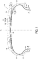
- the carcass ply layer 12 includes carcass ply members 12a, 12b that are formed from organic fibers covered with rubber and that are wound between the pair of bead cores 16 of an annular shape so as to be formed into a toroidal shape.
- the carcass ply layer 12 is made of the carcass ply members 12a and 12b, but may also be made of a single carcass ply member.
- the belt layer 14 is provided outward of the carcass ply layer 12 in the tire radial direction, and is constituted by two belt members 14a, 14b.
- the bead filler rubber members 22 are provided on the outer side of the bead cores 16 in the tire radial direction so as to be interposed between a portion of the carcass ply layer 12 prior to being wound around the bead cores 16 and a portion of the carcass ply layer 12 after being wound around the bead cores 16.
- the innerliner rubber member 26 is provided on the inner surface of the tire 10 facing a tire cavity region that is filled with air and is surrounded by the tire 10 and the rim.
- the tire 10 includes a belt cover layer 28 formed from organic fiber covered with rubber that covers the belt layer 14 from the outer side in the tire radial direction of the belt layer 14.
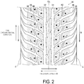
- FIG. 2 is a planar development diagram illustrating a portion of an example of the tread pattern, namely a tread pattern 30, of the tire 10 developed on a plane.
- the tire 10 has a first orientation in the tire circumferential direction designated by rotation direction R.
- Orientation information of the rotation direction R is shown by an information display portion including numbers, symbols, and the like on the sidewall surface of the tire 10.
- stud pins mounted in the tread portion are omitted from the drawing.
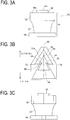
- the stud pins (see FIG. 3A ) are mounted in pin installation holes (black dot portions in FIG. 2 ) illustrated in FIG. 2 .
- the tread pattern 30 includes circumferential main grooves 32, 34, a first inclined groove 36, a second inclined groove 38, and a third inclined groove 40.
- a plurality of the first inclined grooves 36, a plurality of the second inclined grooves 38, and a plurality of the third inclined grooves 40 are each formed at predetermined intervals in the tire circumferential direction (the vertical direction in FIG. 2 ).
- the second inclined groove 38 extends from a region of a land portion located outward of the circumferential main grooves 32, 34 in the tire lateral direction in the direction (upward in FIG. 2 ) opposite the tire rotation direction R and outward in the tire lateral direction.
- the second inclined groove 38 is formed parallel to the first inclined groove 36.
- the second inclined groove 38 extends to the tire shoulder region of the tread portion gradually increasing in groove width, sharply changes in inclination angle in the shoulder region, then extends in the tire circumferential direction, specifically the direction opposite the tire rotation direction R, ending at the pattern end E.
- the second inclined groove 38 is disposed between two of the first inclined grooves 36 adjacent in the tire circumferential direction.
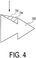
- the tip 52 moves relative to the icy road surface allowing the first portion of the tip 52, which is larger, to scrape against the icy road surface and generate larger resistance.
- the first portion of the tip 52 has a larger size than the second portion to increase the ability to catch on the icy road surface.
- the second portion of the tip 52 has a smaller size than the first portion to make it easier to dig into the ice in an icy road surface.
- a periphery shape of the end surface 52a on the first side with respect to the bottom of the recessed portion 72 includes a first orthogonal line segment that is orthogonal to the axial direction of the axis of symmetry 62, and a periphery shape of the end surface 52a on the second side with respect to the bottom of the recessed portion 72 does not include a second orthogonal line segment that is orthogonal to the axial direction of the axis of symmetry 62 or includes the second orthogonal line segment, with the length of the second orthogonal line segment being less than the length of the first orthogonal line segment.
Landscapes
- Engineering & Computer Science (AREA)
- Mechanical Engineering (AREA)
- Tires In General (AREA)
Claims (11)
- Pneumatique (10) avec une direction de rotation de pneu désignée, le pneumatique (10) comprenant
une partie de bande de roulement avec un clou (50) monté dans la partie de bande de roulement ; le clou (50) comprenant
une pointe (52) comprenant une surface d'extrémité (52a) ayant une forme symétrique de ligne, la surface d'extrémité (52a) étant configurée pour venir en contact avec une surface routière, et
une partie de corps (54) configurée pour fixer la pointe (52) à celle-ci ; la surface d'extrémité (52a) de la pointe (52) configurée pour venir en contact avec une surface routière comprenant
un axe de symétrie (62) qui définit la forme symétrique de ligne,
un centroïde (66) d'une forme de la surface d'extrémité décalé par rapport à un premier côté dans une direction axiale de l'axe de symétrie (62) à partir d'une position centrale (64) d'une plage que la surface d'extrémité couvre dans la direction axiale, et
une paire de parties évidées (72) de part et d'autre de l'axe de symétrie (62), chaque partie évidée (72) étant évidée vers l'intérieur de la surface d'extrémité (52a) et étant fournie sur une périphérie de la surface d'extrémité s'étendant entre une première partie d'extrémité la plus distale (68) et une deuxième partie d'extrémité la plus distale (70), la première partie d'extrémité la plus distale (68) étant située sur l'axe de symétrie (62) de la surface d'extrémité le plus éloigné du centroïde (66) sur le premier côté et la deuxième partie d'extrémité la plus distale (70) étant située sur l'axe de symétrie (62) de la surface d'extrémité le plus éloigné du centroïde (66) sur un deuxième côté opposé au premier côté ; et
le clou (50) étant monté de telle sorte que le deuxième côté, par opposition au premier côté, corresponde à un côté avant dans une direction de rotation de pneu R. - Clou (50) pouvant être monté dans une partie de bande de roulement d'un pneumatique (10), le clou (50) comprenant :une partie de corps (54) configurée pour fixer une pointe (52) à celle-ci ;une pointe (52) comprenant une surface d'extrémité (52a) configurée pour venir en contact avec une surface routière, etla surface d'extrémité (52a) de la pointe (52) comprenant un axe de symétrie (62) qui définit une forme symétrique de ligne de la surface d'extrémité,un centroïde (66) d'une forme de la surface d'extrémité décalé par rapport à un premier côté dans une direction axiale de l'axe de symétrie (62) à partir d'une position centrale (64) d'une plage que la surface d'extrémité couvre dans la direction axiale, etune paire de parties évidées (72) de part et d'autre de l'axe de symétrie (62), chaque partie évidée (72) étant évidée vers l'intérieur de la surface d'extrémité (52a) et étant fournie sur une périphérie de la surface d'extrémité s'étendant entre une première partie d'extrémité la plus distale (68) et une deuxième partie d'extrémité la plus distale (70), la première partie d'extrémité la plus distale (68) étant située sur l'axe de symétrie (62) de la surface d'extrémité le plus éloigné du centroïde (66) sur le premier côté et la deuxième partie d'extrémité la plus distale (70) étant située sur l'axe de symétrie (62) de la surface d'extrémité le plus éloigné du centroïde (66) sur un deuxième côté opposé au premier côté.
- Clou (50) selon la revendication 2, dans lequel une deuxième longueur d'une deuxième périphérie de la surface d'extrémité (52a) qui passe d'un fond de l'une de la paire de parties évidées (72) à un fond d'une autre de la paire de parties évidées (72) à travers la deuxième partie d'extrémité la plus distale (70) sur le deuxième côté par rapport à chaque fond de la paire de parties évidées (72) est inférieure à une première longueur d'une première périphérie de la surface d'extrémité qui passe d'un fond de l'une de la paire de parties évidées (72) à un fond d'une autre de la paire de parties évidées (72) à travers la première partie d'extrémité la plus distale (68) sur le premier côté par rapport à chaque fond de la paire de parties évidées (72).
- Clou (50) selon la revendication 2 ou 3, dans lequel une première largeur maximale dans une direction orthogonale à la direction axiale d'une partie de la surface d'extrémité (52a) sur le premier côté par rapport à chaque fond de la paire de parties évidées (72) est supérieure à une deuxième largeur maximale dans la direction orthogonale à la direction axiale d'une partie de la surface d'extrémité sur le deuxième côté par rapport à chaque fond de la paire de parties évidées (72).
- Clou (50) selon l'une quelconque des revendications 2 à 4, dans lequel une première zone de la partie de la surface d'extrémité (52a) sur le premier côté par rapport à chaque fond de la paire de parties évidées (72) est supérieure à une deuxième zone de la partie de la surface d'extrémité sur le deuxième côté par rapport à chaque fond de la paire de parties évidées (72).
- Clou (50) selon l'une quelconque des revendications 2 à 5, dans lequel dans la direction axiale une position de chaque fond de la paire de parties évidées (72) est située sur le deuxième côté du centroïde (66).
- Clou (50) selon l'une quelconque des revendications 2 à 6, dans lequel une forme de périphérie de la surface d'extrémité (52a) sur le premier côté par rapport à chacune de la paire de parties évidées (72) comprend un premier segment de ligne orthogonal orthogonal à la direction axiale ; et
une forme de périphérie de la surface d'extrémité sur le deuxième côté par rapport à chacune de la paire de parties évidées (72) comprend un deuxième segment de ligne orthogonal orthogonal à la direction axiale avec une longueur inférieure à celle du premier segment de ligne orthogonal, ou ne comprend pas le deuxième segment de ligne orthogonal. - Clou (50) selon l'une quelconque des revendications 2 à 7, dans lequel une première forme de périphérie de la surface d'extrémité (52a) sur le premier côté par rapport à chaque fond de la paire de parties évidées (72) a une forme partiellement identique à une forme élargie qui est élargie, d'un facteur d'échelle prédéterminé, d'une deuxième forme de périphérie de la surface d'extrémité sur le deuxième côté par rapport à chaque fond de la paire de parties évidées (72).
- Clou (50) selon la revendication 8, dans lequel la première forme de périphérie ou la forme élargie est un cercle parfait, une ellipse ou une partie d'un polygone.
- Clou (50) selon l'une quelconque des revendications 2 à 9, dans lequel une distance L1 d'une position dans la direction axiale de chaque fond de la paire de parties évidées (72) à la première partie d'extrémité la plus distale (68) et une distance L2 d'une position dans la direction axiale de chaque fond de la paire de parties évidées (72) à la deuxième partie d'extrémité la plus distale (70) ont un rapport L1/L2 allant de 1,0 à 5,0.
- Clou (50) selon l'une quelconque des revendications 2 à 10, dans lequel la partie de corps (54) comprend une surface d'extrémité supérieure (54a) ayant une forme symétrique de ligne fournie de telle sorte que la pointe (52) fait saillie à partir de celle-ci ; et la surface d'extrémité supérieure (54a) comprend
un axe de symétrie de surface d'extrémité supérieure (82) qui définit la forme symétrique de ligne,
un centroïde de surface d'extrémité supérieure (86) d'une forme de la surface d'extrémité supérieure (54a) décalé par rapport au premier côté à partir d'une position centrale (64) d'une plage que la surface d'extrémité supérieure (54a) couvre dans une direction axiale de l'axe de symétrie de surface d'extrémité supérieure (82), et
une paire de parties évidées de surface d'extrémité supérieure (92) de part et d'autre de l'axe de symétrie de surface d'extrémité supérieure (82), chaque partie évidée de surface d'extrémité supérieure (92) étant évidée vers l'intérieur de la surface d'extrémité supérieure (54a) et étant fournie sur une périphérie de la surface d'extrémité supérieure (54a) s'étendant entre une troisième partie d'extrémité la plus distale (88) et une quatrième partie d'extrémité la plus distale (90) de la périphérie de la surface d'extrémité supérieure (54a), la troisième partie d'extrémité la plus distale (88) étant située sur l'axe de symétrie de surface d'extrémité supérieure (82) le plus éloigné du centroïde de surface d'extrémité supérieure (86) sur le premier côté et la quatrième partie d'extrémité la plus distale (90) étant située sur l'axe de symétrie de surface d'extrémité supérieure (82) le plus éloigné du centroïde de surface d'extrémité supérieure (86) sur le deuxième côté.
Applications Claiming Priority (2)
| Application Number | Priority Date | Filing Date | Title |
|---|---|---|---|
| JP2015199677 | 2015-10-07 | ||
| PCT/JP2016/078648 WO2017061316A1 (fr) | 2015-10-07 | 2016-09-28 | Pneumatique et plot |
Publications (3)
| Publication Number | Publication Date |
|---|---|
| EP3360700A1 EP3360700A1 (fr) | 2018-08-15 |
| EP3360700A4 EP3360700A4 (fr) | 2019-05-22 |
| EP3360700B1 true EP3360700B1 (fr) | 2020-04-29 |
Family
ID=58487615
Family Applications (1)
| Application Number | Title | Priority Date | Filing Date |
|---|---|---|---|
| EP16853470.9A Active EP3360700B1 (fr) | 2015-10-07 | 2016-09-28 | Pneumatique et plot |
Country Status (6)
| Country | Link |
|---|---|
| US (1) | US11040579B2 (fr) |
| EP (1) | EP3360700B1 (fr) |
| JP (1) | JP6304399B2 (fr) |
| CN (1) | CN108025602B (fr) |
| RU (1) | RU2681454C1 (fr) |
| WO (1) | WO2017061316A1 (fr) |
Families Citing this family (3)
| Publication number | Priority date | Publication date | Assignee | Title |
|---|---|---|---|---|
| WO2020012281A1 (fr) * | 2018-07-13 | 2020-01-16 | Pirelli Tyre S.P.A. | Pneu clouté pour roues de véhicule |
| EP3674105B1 (fr) * | 2018-12-28 | 2024-12-04 | Sumitomo Rubber Industries, Ltd. | Dispositif d'adhérence sur glace avancé et pneu comportant un dispositif d'adhérence sur glace avancé |
| JP7243272B2 (ja) * | 2019-02-20 | 2023-03-22 | 住友ゴム工業株式会社 | スタッダブルタイヤ |
Family Cites Families (12)
| Publication number | Priority date | Publication date | Assignee | Title |
|---|---|---|---|---|
| DE2804939A1 (de) * | 1978-02-06 | 1979-08-09 | Anton Wallner | Gleitschutzkoerper fuer luftreifen |
| FI123775B (fi) * | 2002-12-11 | 2013-10-31 | Nokian Renkaat Oyj | Ei-pyöreiden liukuestenastojen asennus ajoneuvon renkaaseen |
| RU2340463C1 (ru) * | 2007-04-18 | 2008-12-10 | Дмитрий Станиславович Евстифеев | Шип противоскольжения покрышки колеса транспортного средства (варианты), покрышка с шипами противоскольжения |
| JP5706192B2 (ja) | 2011-03-01 | 2015-04-22 | 株式会社ブリヂストン | タイヤ用スパイク |
| US20130000807A1 (en) * | 2011-06-28 | 2013-01-03 | Frederic Michel-Jean Pons | Anti-skid stud for insertion into the tread of a vehicle tire and pneumatic tire comprising such anti-skid studs |
| JP5997519B2 (ja) * | 2012-07-04 | 2016-09-28 | 株式会社ブリヂストン | ピン、タイヤ用スタッドおよびスパイクタイヤ |
| JP5997518B2 (ja) * | 2012-07-04 | 2016-09-28 | 株式会社ブリヂストン | ピン、タイヤ用スタッドおよびスパイクタイヤ |
| CN104955662B (zh) | 2013-02-06 | 2017-08-11 | 倍耐力轮胎股份公司 | 装防滑钉的轮胎以及改善装防滑钉的轮胎性能的方法 |
| JP5702817B2 (ja) * | 2013-03-19 | 2015-04-15 | 株式会社ブリヂストン | スタッドピンおよびこれを用いたタイヤ |
| JP6087247B2 (ja) * | 2013-09-18 | 2017-03-01 | 東洋ゴム工業株式会社 | タイヤ用スタッド及び空気入りスタッドタイヤ |
| JP2015136942A (ja) | 2014-01-20 | 2015-07-30 | 横浜ゴム株式会社 | スタッドピン及び空気入りタイヤ |
| US20170069075A1 (en) | 2015-09-04 | 2017-03-09 | Canon Kabushiki Kaisha | Classifier generation apparatus, defective/non-defective determination method, and program |
-
2016
- 2016-09-28 EP EP16853470.9A patent/EP3360700B1/fr active Active
- 2016-09-28 WO PCT/JP2016/078648 patent/WO2017061316A1/fr not_active Ceased
- 2016-09-28 RU RU2018115901A patent/RU2681454C1/ru active
- 2016-09-28 JP JP2016559671A patent/JP6304399B2/ja not_active Expired - Fee Related
- 2016-09-28 US US15/762,540 patent/US11040579B2/en not_active Expired - Fee Related
- 2016-09-28 CN CN201680054341.4A patent/CN108025602B/zh active Active
Non-Patent Citations (1)
| Title |
|---|
| None * |
Also Published As
| Publication number | Publication date |
|---|---|
| CN108025602A (zh) | 2018-05-11 |
| CN108025602B (zh) | 2020-05-19 |
| US11040579B2 (en) | 2021-06-22 |
| EP3360700A1 (fr) | 2018-08-15 |
| WO2017061316A1 (fr) | 2017-04-13 |
| US20190077202A1 (en) | 2019-03-14 |
| JPWO2017061316A1 (ja) | 2017-10-19 |
| RU2681454C1 (ru) | 2019-03-06 |
| EP3360700A4 (fr) | 2019-05-22 |
| JP6304399B2 (ja) | 2018-04-04 |
Similar Documents
| Publication | Publication Date | Title |
|---|---|---|
| US10618357B2 (en) | Stud pin, and pneumatic tire | |
| EP3025880B1 (fr) | Clou et bandage pneumatique | |
| EP2583840B1 (fr) | Pneu | |
| EP3375644B1 (fr) | Clou et pneu clouté | |
| RU2643899C1 (ru) | Пневматическая шина | |
| JP2013071633A (ja) | 空気入りタイヤ | |
| US10647163B2 (en) | Stud pin and pneumatic tire | |
| WO2020204942A1 (fr) | Pneu de camion à lamelle circonférentielle ayant des micro-lamelles aveugles | |
| EP3590735B1 (fr) | Clou antidérapant et pneu clouté | |
| US11040579B2 (en) | Pneumatic tire and stud pin | |
| RU2750755C1 (ru) | Шипуемая шина и пневматическая шина | |
| EP3590736B1 (fr) | Clou antidérapant et pneu clouté | |
| EP3785941B1 (fr) | Clou et pneu clouté | |
| EP3590737B1 (fr) | Clou et pneu clouté | |
| US11524530B2 (en) | Stud pin and studded tire |
Legal Events
| Date | Code | Title | Description |
|---|---|---|---|
| STAA | Information on the status of an ep patent application or granted ep patent |
Free format text: STATUS: THE INTERNATIONAL PUBLICATION HAS BEEN MADE |
|
| PUAI | Public reference made under article 153(3) epc to a published international application that has entered the european phase |
Free format text: ORIGINAL CODE: 0009012 |
|
| STAA | Information on the status of an ep patent application or granted ep patent |
Free format text: STATUS: REQUEST FOR EXAMINATION WAS MADE |
|
| 17P | Request for examination filed |
Effective date: 20180507 |
|
| AK | Designated contracting states |
Kind code of ref document: A1 Designated state(s): AL AT BE BG CH CY CZ DE DK EE ES FI FR GB GR HR HU IE IS IT LI LT LU LV MC MK MT NL NO PL PT RO RS SE SI SK SM TR |
|
| AX | Request for extension of the european patent |
Extension state: BA ME |
|
| DAV | Request for validation of the european patent (deleted) | ||
| DAX | Request for extension of the european patent (deleted) | ||
| A4 | Supplementary search report drawn up and despatched |
Effective date: 20190426 |
|
| RIC1 | Information provided on ipc code assigned before grant |
Ipc: B60C 11/16 20060101AFI20190418BHEP |
|
| GRAP | Despatch of communication of intention to grant a patent |
Free format text: ORIGINAL CODE: EPIDOSNIGR1 |
|
| STAA | Information on the status of an ep patent application or granted ep patent |
Free format text: STATUS: GRANT OF PATENT IS INTENDED |
|
| INTG | Intention to grant announced |
Effective date: 20200221 |
|
| GRAS | Grant fee paid |
Free format text: ORIGINAL CODE: EPIDOSNIGR3 |
|
| GRAA | (expected) grant |
Free format text: ORIGINAL CODE: 0009210 |
|
| STAA | Information on the status of an ep patent application or granted ep patent |
Free format text: STATUS: THE PATENT HAS BEEN GRANTED |
|
| AK | Designated contracting states |
Kind code of ref document: B1 Designated state(s): AL AT BE BG CH CY CZ DE DK EE ES FI FR GB GR HR HU IE IS IT LI LT LU LV MC MK MT NL NO PL PT RO RS SE SI SK SM TR |
|
| REG | Reference to a national code |
Ref country code: GB Ref legal event code: FG4D |
|
| REG | Reference to a national code |
Ref country code: CH Ref legal event code: EP |
|
| REG | Reference to a national code |
Ref country code: AT Ref legal event code: REF Ref document number: 1262745 Country of ref document: AT Kind code of ref document: T Effective date: 20200515 |
|
| REG | Reference to a national code |
Ref country code: DE Ref legal event code: R096 Ref document number: 602016035371 Country of ref document: DE |
|
| REG | Reference to a national code |
Ref country code: IE Ref legal event code: FG4D |
|
| REG | Reference to a national code |
Ref country code: FI Ref legal event code: FGE |
|
| REG | Reference to a national code |
Ref country code: NL Ref legal event code: MP Effective date: 20200429 |
|
| REG | Reference to a national code |
Ref country code: LT Ref legal event code: MG4D |
|
| PG25 | Lapsed in a contracting state [announced via postgrant information from national office to epo] |
Ref country code: GR Free format text: LAPSE BECAUSE OF FAILURE TO SUBMIT A TRANSLATION OF THE DESCRIPTION OR TO PAY THE FEE WITHIN THE PRESCRIBED TIME-LIMIT Effective date: 20200730 Ref country code: SE Free format text: LAPSE BECAUSE OF FAILURE TO SUBMIT A TRANSLATION OF THE DESCRIPTION OR TO PAY THE FEE WITHIN THE PRESCRIBED TIME-LIMIT Effective date: 20200429 Ref country code: IS Free format text: LAPSE BECAUSE OF FAILURE TO SUBMIT A TRANSLATION OF THE DESCRIPTION OR TO PAY THE FEE WITHIN THE PRESCRIBED TIME-LIMIT Effective date: 20200829 Ref country code: NO Free format text: LAPSE BECAUSE OF FAILURE TO SUBMIT A TRANSLATION OF THE DESCRIPTION OR TO PAY THE FEE WITHIN THE PRESCRIBED TIME-LIMIT Effective date: 20200729 Ref country code: PT Free format text: LAPSE BECAUSE OF FAILURE TO SUBMIT A TRANSLATION OF THE DESCRIPTION OR TO PAY THE FEE WITHIN THE PRESCRIBED TIME-LIMIT Effective date: 20200831 Ref country code: LT Free format text: LAPSE BECAUSE OF FAILURE TO SUBMIT A TRANSLATION OF THE DESCRIPTION OR TO PAY THE FEE WITHIN THE PRESCRIBED TIME-LIMIT Effective date: 20200429 |
|
| REG | Reference to a national code |
Ref country code: AT Ref legal event code: MK05 Ref document number: 1262745 Country of ref document: AT Kind code of ref document: T Effective date: 20200429 |
|
| PG25 | Lapsed in a contracting state [announced via postgrant information from national office to epo] |
Ref country code: LV Free format text: LAPSE BECAUSE OF FAILURE TO SUBMIT A TRANSLATION OF THE DESCRIPTION OR TO PAY THE FEE WITHIN THE PRESCRIBED TIME-LIMIT Effective date: 20200429 Ref country code: HR Free format text: LAPSE BECAUSE OF FAILURE TO SUBMIT A TRANSLATION OF THE DESCRIPTION OR TO PAY THE FEE WITHIN THE PRESCRIBED TIME-LIMIT Effective date: 20200429 Ref country code: RS Free format text: LAPSE BECAUSE OF FAILURE TO SUBMIT A TRANSLATION OF THE DESCRIPTION OR TO PAY THE FEE WITHIN THE PRESCRIBED TIME-LIMIT Effective date: 20200429 Ref country code: BG Free format text: LAPSE BECAUSE OF FAILURE TO SUBMIT A TRANSLATION OF THE DESCRIPTION OR TO PAY THE FEE WITHIN THE PRESCRIBED TIME-LIMIT Effective date: 20200729 |
|
| PG25 | Lapsed in a contracting state [announced via postgrant information from national office to epo] |
Ref country code: AL Free format text: LAPSE BECAUSE OF FAILURE TO SUBMIT A TRANSLATION OF THE DESCRIPTION OR TO PAY THE FEE WITHIN THE PRESCRIBED TIME-LIMIT Effective date: 20200429 Ref country code: NL Free format text: LAPSE BECAUSE OF FAILURE TO SUBMIT A TRANSLATION OF THE DESCRIPTION OR TO PAY THE FEE WITHIN THE PRESCRIBED TIME-LIMIT Effective date: 20200429 |
|
| PG25 | Lapsed in a contracting state [announced via postgrant information from national office to epo] |
Ref country code: SM Free format text: LAPSE BECAUSE OF FAILURE TO SUBMIT A TRANSLATION OF THE DESCRIPTION OR TO PAY THE FEE WITHIN THE PRESCRIBED TIME-LIMIT Effective date: 20200429 Ref country code: EE Free format text: LAPSE BECAUSE OF FAILURE TO SUBMIT A TRANSLATION OF THE DESCRIPTION OR TO PAY THE FEE WITHIN THE PRESCRIBED TIME-LIMIT Effective date: 20200429 Ref country code: DK Free format text: LAPSE BECAUSE OF FAILURE TO SUBMIT A TRANSLATION OF THE DESCRIPTION OR TO PAY THE FEE WITHIN THE PRESCRIBED TIME-LIMIT Effective date: 20200429 Ref country code: ES Free format text: LAPSE BECAUSE OF FAILURE TO SUBMIT A TRANSLATION OF THE DESCRIPTION OR TO PAY THE FEE WITHIN THE PRESCRIBED TIME-LIMIT Effective date: 20200429 Ref country code: RO Free format text: LAPSE BECAUSE OF FAILURE TO SUBMIT A TRANSLATION OF THE DESCRIPTION OR TO PAY THE FEE WITHIN THE PRESCRIBED TIME-LIMIT Effective date: 20200429 Ref country code: IT Free format text: LAPSE BECAUSE OF FAILURE TO SUBMIT A TRANSLATION OF THE DESCRIPTION OR TO PAY THE FEE WITHIN THE PRESCRIBED TIME-LIMIT Effective date: 20200429 Ref country code: AT Free format text: LAPSE BECAUSE OF FAILURE TO SUBMIT A TRANSLATION OF THE DESCRIPTION OR TO PAY THE FEE WITHIN THE PRESCRIBED TIME-LIMIT Effective date: 20200429 Ref country code: CZ Free format text: LAPSE BECAUSE OF FAILURE TO SUBMIT A TRANSLATION OF THE DESCRIPTION OR TO PAY THE FEE WITHIN THE PRESCRIBED TIME-LIMIT Effective date: 20200429 |
|
| REG | Reference to a national code |
Ref country code: DE Ref legal event code: R097 Ref document number: 602016035371 Country of ref document: DE |
|
| PG25 | Lapsed in a contracting state [announced via postgrant information from national office to epo] |
Ref country code: PL Free format text: LAPSE BECAUSE OF FAILURE TO SUBMIT A TRANSLATION OF THE DESCRIPTION OR TO PAY THE FEE WITHIN THE PRESCRIBED TIME-LIMIT Effective date: 20200429 Ref country code: SK Free format text: LAPSE BECAUSE OF FAILURE TO SUBMIT A TRANSLATION OF THE DESCRIPTION OR TO PAY THE FEE WITHIN THE PRESCRIBED TIME-LIMIT Effective date: 20200429 |
|
| PLBE | No opposition filed within time limit |
Free format text: ORIGINAL CODE: 0009261 |
|
| STAA | Information on the status of an ep patent application or granted ep patent |
Free format text: STATUS: NO OPPOSITION FILED WITHIN TIME LIMIT |
|
| 26N | No opposition filed |
Effective date: 20210201 |
|
| REG | Reference to a national code |
Ref country code: CH Ref legal event code: PL |
|
| GBPC | Gb: european patent ceased through non-payment of renewal fee |
Effective date: 20200928 |
|
| PG25 | Lapsed in a contracting state [announced via postgrant information from national office to epo] |
Ref country code: SI Free format text: LAPSE BECAUSE OF FAILURE TO SUBMIT A TRANSLATION OF THE DESCRIPTION OR TO PAY THE FEE WITHIN THE PRESCRIBED TIME-LIMIT Effective date: 20200429 |
|
| REG | Reference to a national code |
Ref country code: BE Ref legal event code: MM Effective date: 20200930 |
|
| PG25 | Lapsed in a contracting state [announced via postgrant information from national office to epo] |
Ref country code: LU Free format text: LAPSE BECAUSE OF NON-PAYMENT OF DUE FEES Effective date: 20200928 |
|
| PG25 | Lapsed in a contracting state [announced via postgrant information from national office to epo] |
Ref country code: FR Free format text: LAPSE BECAUSE OF NON-PAYMENT OF DUE FEES Effective date: 20200930 |
|
| PG25 | Lapsed in a contracting state [announced via postgrant information from national office to epo] |
Ref country code: LI Free format text: LAPSE BECAUSE OF NON-PAYMENT OF DUE FEES Effective date: 20200930 Ref country code: IE Free format text: LAPSE BECAUSE OF NON-PAYMENT OF DUE FEES Effective date: 20200928 Ref country code: GB Free format text: LAPSE BECAUSE OF NON-PAYMENT OF DUE FEES Effective date: 20200928 Ref country code: BE Free format text: LAPSE BECAUSE OF NON-PAYMENT OF DUE FEES Effective date: 20200930 Ref country code: CH Free format text: LAPSE BECAUSE OF NON-PAYMENT OF DUE FEES Effective date: 20200930 |
|
| PG25 | Lapsed in a contracting state [announced via postgrant information from national office to epo] |
Ref country code: TR Free format text: LAPSE BECAUSE OF FAILURE TO SUBMIT A TRANSLATION OF THE DESCRIPTION OR TO PAY THE FEE WITHIN THE PRESCRIBED TIME-LIMIT Effective date: 20200429 Ref country code: MT Free format text: LAPSE BECAUSE OF FAILURE TO SUBMIT A TRANSLATION OF THE DESCRIPTION OR TO PAY THE FEE WITHIN THE PRESCRIBED TIME-LIMIT Effective date: 20200429 Ref country code: CY Free format text: LAPSE BECAUSE OF FAILURE TO SUBMIT A TRANSLATION OF THE DESCRIPTION OR TO PAY THE FEE WITHIN THE PRESCRIBED TIME-LIMIT Effective date: 20200429 |
|
| PG25 | Lapsed in a contracting state [announced via postgrant information from national office to epo] |
Ref country code: MK Free format text: LAPSE BECAUSE OF FAILURE TO SUBMIT A TRANSLATION OF THE DESCRIPTION OR TO PAY THE FEE WITHIN THE PRESCRIBED TIME-LIMIT Effective date: 20200429 Ref country code: MC Free format text: LAPSE BECAUSE OF FAILURE TO SUBMIT A TRANSLATION OF THE DESCRIPTION OR TO PAY THE FEE WITHIN THE PRESCRIBED TIME-LIMIT Effective date: 20200429 |
|
| P01 | Opt-out of the competence of the unified patent court (upc) registered |
Effective date: 20230512 |
|
| PGFP | Annual fee paid to national office [announced via postgrant information from national office to epo] |
Ref country code: FI Payment date: 20250912 Year of fee payment: 10 |
|
| PGFP | Annual fee paid to national office [announced via postgrant information from national office to epo] |
Ref country code: DE Payment date: 20250805 Year of fee payment: 10 |