EP3360702A1 - Soupape du pneu pour un pneumatique d'un véhicule - Google Patents
Soupape du pneu pour un pneumatique d'un véhicule Download PDFInfo
- Publication number
- EP3360702A1 EP3360702A1 EP17207428.8A EP17207428A EP3360702A1 EP 3360702 A1 EP3360702 A1 EP 3360702A1 EP 17207428 A EP17207428 A EP 17207428A EP 3360702 A1 EP3360702 A1 EP 3360702A1
- Authority
- EP
- European Patent Office
- Prior art keywords
- valve
- tire
- tire pressure
- cap
- union nut
- Prior art date
- Legal status (The legal status is an assumption and is not a legal conclusion. Google has not performed a legal analysis and makes no representation as to the accuracy of the status listed.)
- Granted
Links
Images


Classifications
-
- B—PERFORMING OPERATIONS; TRANSPORTING
- B60—VEHICLES IN GENERAL
- B60C—VEHICLE TYRES; TYRE INFLATION; TYRE CHANGING; CONNECTING VALVES TO INFLATABLE ELASTIC BODIES IN GENERAL; DEVICES OR ARRANGEMENTS RELATED TO TYRES
- B60C23/00—Devices for measuring, signalling, controlling, or distributing tyre pressure or temperature, specially adapted for mounting on vehicles; Arrangement of tyre inflating devices on vehicles, e.g. of pumps or of tanks; Tyre cooling arrangements
- B60C23/02—Signalling devices actuated by tyre pressure
- B60C23/04—Signalling devices actuated by tyre pressure mounted on the wheel or tyre
- B60C23/0491—Constructional details of means for attaching the control device
- B60C23/0494—Valve stem attachments positioned inside the tyre chamber
-
- B—PERFORMING OPERATIONS; TRANSPORTING
- B60—VEHICLES IN GENERAL
- B60C—VEHICLE TYRES; TYRE INFLATION; TYRE CHANGING; CONNECTING VALVES TO INFLATABLE ELASTIC BODIES IN GENERAL; DEVICES OR ARRANGEMENTS RELATED TO TYRES
- B60C29/00—Arrangements of tyre-inflating valves to tyres or rims; Accessories for tyre-inflating valves, not otherwise provided for
- B60C29/06—Accessories for tyre-inflating valves, e.g. housings, guards, covers for valve caps, locks, not otherwise provided for
- B60C29/066—Valve caps
Definitions
- Tire valves of the generic type are used to pump compressed air into the pneumatic tire of a motor vehicle or also to release compressed air from the pneumatic tire. Accordingly, based on the flow direction of the air when inflating the pneumatic tire, such tire valves have an air inlet end for connecting a compressed air source and an air outlet end for positioning inside the pneumatic tire.
- the connection of the compressed air source is usually via a clamping element of an air pump or a compressor which is clamped on an end-side thread on the air inlet end of a valve stem of the tire valve.
- Such an air pressure sensor has a housing, which according to an embodiment, as it relates to the present invention, hinged or fastened to the valve stem to the housing to the rim well of a To press pneumatic tire receiving rim.
- a screw designed as a hollow screw which engages in a valve bore of the valve stem and by tightening the housing of the air pressure sensor is pressed against the rim base.
- the fastening screw is screwed into a threaded bore at the air outlet end of the valve stem, which causes a deflection of the housing on the rim and in a further screwing the union nut on the external thread of the valve stem with a correspondingly larger Aufschraubmoment the predetermined breaking element is sheared off and the union nut relative to the valve stem twisted and thereby tightened against the rim or the outside of the rim base to clamp the rim between the union nut and provided at the air outlet end of the valve stem stop.
- the arrangement of the predetermined breaking element within the union nut has proved to be disadvantageous in manufacturing, since the production tool must be placed in the limited space within the union nut. Even with quality control, the measurement processes are very disadvantageous because of the limited space inside the union nut. Furthermore, there are disadvantages in incorrect installation, since the shearing of the predetermined breaking element is not immediately visible to a fitter.
- the union nut can not be reused.
- the union nut or valve made of aluminum is coated against corrosion due to its use in humid environments. After the installation has taken place, corrosion occurs on the part freed from the coating due to the shearing off of the predetermined breaking element.
- WO 2014/108926 A1 suggests starting from the EP 1 277 601 A2 not to provide the break element on the nut but on the valve stem itself, thereby using standard union nuts can.
- the aforementioned embodiments already provide over older embodiments, which provide a screw drive of the fastening screw in the region of the air outlet end of the valve stem, see for example EP 0 751 017 A2 , allow in practice a much easier installation of the air pressure sensor on the rim, is to be regarded as disadvantageous in the embodiments mentioned that the union nut due to their interaction with the predetermined breaking element on the valve stem or due to the radially inwardly of the union nut projecting predetermined breaking element always on the Valve stem can be mounted if previously a valve bore at the air inlet end occlusive valve cap has been removed.
- valve caps Due to the high time pressure and the large number of installed air pressure sensors in workshops, the necessary removal and later re-screwing the valve caps has proven in practice as a significant disadvantage. On the other hand, if the valve caps are only loosely attached to a new tire valve to prevent them from being unscrewed, there is a risk that the valve cap will be lost during transport. In addition, there is a risk of contamination of the Filling opening in the valve, if the cap is enclosed only loosely during transport.
- the present invention has for its object to facilitate the installation of the tire pressure monitoring system and to make cheaper.
- valve cap has a coupling portion and the union nut has a counter coupling portion, wherein at least temporarily the coupling portion and the counter coupling portion have a positive and / or non-positive connection during assembly of the tire pressure sensor.
- a tire pressure control system which is characterized by a functional design and has a simple and inexpensive construction.
- the coupling of the union nut with the tire valve by means of the coupling portion of the valve cap and the counter coupling portion of the union nut takes place.
- the invention differs from the prior art, in which a type of predetermined breaking point is formed concealed inside a cap nut, that the separation of the cap into two sections in the present invention is optically detectable. Accordingly, it is visually recognizable to the fitter whether the valve cap required for a coupling has been used before or not and whether the screwdriving process has actually been carried out correctly.
- the coupling portion is formed integrally with the valve cap, in particular as an injection molded part, it is possible to achieve a reduction in the number of components of the tire pressure monitoring system, because there is no need for a separate predetermined breaking element.
- the valve cap is already provided as standard to seal the tire valve and protect it from dirt.
- an assembly step can be saved because the valve cap is already delivered pre-assembled on the tire valve and does not have to be removed during assembly to a rim. For large companies, which have to mount large numbers of tire pressure sensors to the rim, the air is introduced with a special device through a gap between the rim and tire.
- the coupling portion of the valve cap has at least one stop, which is designed in particular as a circumferential outwardly directed projection.
- the stop serves as a predetermined breaking element.
- Very cost-effective and simple is the construction, if the articulation of the sensor housing takes place on the rim with the stop itself, so that the predetermined breaking point does not need to be provided separately.
- the stop is connectable as a separate circumferential ring with the valve cap.
- the one standard Valve cap can be used.
- a reuse of the cap is given by. It is particularly advantageous if the valve cap and the circumferential ring have a positive and / or non-positive, in particular by shrinking, and / or cohesive connection.
- the valve cap has a predetermined breaking point. This ensures that after the separation of the coupling portion of the valve cap can be used as a seal. Furthermore, the shape of the predetermined breaking point can be selected with a known notch effect number to achieve reproducible separation of the two sections and a predetermined Aufschraubmoment.
- the valve cap has a cap portion, wherein the cap portion and the coupling portion are connected to the predetermined breaking point. This ensures that the length of the cap portion of the valve cap is adjustable by an axial displacement of the predetermined breaking point on the valve cap. Furthermore, the shape of the predetermined breaking point can be selected with a known notch effect number to achieve reproducible separation of the two sections and a predetermined Aufschraubmoment.
- the union nut has an inner surface, wherein on the inner surface of the union nut a counter-stop is arranged, which is complementary to the coupling portion of the valve cap. This ensures that the tensile force generated by the screw-on torque applied to the union nut is optimally transferred.
- valve cap has a material weakening, which is designed as a predetermined breaking point.
- the material weakening is designed as a circumferentially radially oriented from outside to inside groove. This ensures that a separation edge formed between the coupling section and the cap section after a fracture has an externally clean separation.
- At least one latching connection for connecting the union nut is arranged on the valve cap.
- This solution is characterized in particular by the fact that in the absence of special devices for inflating the tire between the tire and rim, the valve cap is not pre-assembled with the valve, but with the union nut.
- the latching connection forms both an anti-rotation and an axial securing in the direction of a central axis of the valve cap.
- the preassembled mounting unit is screwed onto the tire valve as far as the stop of the valve cap.
- the coupling between the union nut and the tire valve by means of the valve cap to secure the tire pressure sensor.
- decoupling of the mounting unit takes place to secure the tire valve to the rim.
- the valve cap can be removed and the tire inflated with air.
- the manufacturing process is improved when the union nut has an inside diameter d.
- valve cap has a cap portion with an outer diameter D and the union nut has a portion with an inner diameter d, wherein the outer diameter D is smaller than the inner diameter d formed or the outer diameter D is equal to the inner diameter d.
- the installation of the tire pressure monitoring system can be further simplified if the valve cap and the union nut with a clearance fit, or with a press fit, or with the latching connection can be connected such that the valve cap and the union nut form a, in particular self-holding, mounting unit.
- the cap portion and the coupling portion of the union nut after exceeding a predetermined Aufschraubmoments, in particular from 2.8 to 4.2 Nm, are decoupled from each other.
- a predetermined Aufschraubmoments in particular from 2.8 to 4.2 Nm
- the manufacturing process can be improved if the valve cap made of plastic, in particular by injection molding, is formed.
- FIG. 1 the rear of a vehicle 1 and a seated on a rim 2, rear pneumatic tires 3 can be seen. From the rim 2 protrudes a tire valve 4, at the valve foot 8, a tire pressure sensor 5 is fixed, as it is from the Figures 2 and 3 is apparent.
- FIG. 3 shows a perspective view of a tire pressure monitoring system 6 according to the invention, wherein the contour of the rim 2 for reasons of clarity in the FIG. 3 only hinted at.
- the tire pressure monitoring system 6 according to the invention is also shown in a perspective view, but here in a single part illustration.
- the rim 2 is a purely from the FIGS. 5 to 10 formed apparent passage opening 27, through which a valve stem 7 of the tire valve 4 is inserted.
- the tire valve 4 has an axially extending valve bore 9 (see, inter alia FIGS. 5 to 10 ), which opens into a dome-shaped end face 10 of the valve foot 8.
- a valve cap 17 can be screwed onto the end.
- a seal 30 may be arranged in the valve cap 17, a seal 30 may be arranged.
- the tire pressure sensor 5 is fixed in a known manner to the tire valve 4 via a screw element 12, which may be a hollow screw, for example, by screwing the screw element 12 into the valve bore 9.
- the dome-shaped end face 10 of the valve foot 8 in a cavity 32 of the housing of the tire pressure sensor 5 (see, for example FIG. 4 ) arranged.
- the tire valve 4 is fixed by means of a union nut 14 on the rim 2, which is screwed onto a threaded portion 15, wherein the Threaded portion 15 is formed on the valve stem 7 of the tire valve 4.
- an elastic ring 16 is pushed onto the valve stem 7, the inside of the rim 2 is a kind of damper between the rim 2 and the tire pressure sensor 5.
- a rim protection ring 26 is arranged on the outside of the rim 2. The rim protection ring 26 is pushed onto the valve stem 7 and arranged between the union nut 14 and the rim 2.
- valve cap 17 has a coupling portion 19 and the union nut 14 has a counter coupling portion 13, wherein at least temporarily the coupling portion 19 and the counter coupling portion 13 have a positive and / or non-positive connection during assembly of the tire pressure sensor 5, as will be discussed in detail below becomes.
- the tire valve 4 is supplied with the valve cap 17.
- a circumferentially directed outward projection is formed, which serves as a stop 20 for transmitting the force exerted on the nut 14 Aufschraubmoments.
- a counter-abutment 23 is arranged on the inner surface of the union nut 14.
- the dome-shaped end face 10 of the valve foot 8 which is arranged in the cavity 32 of the tire pressure sensor 5, allows a relative pivoting movement.
- a first assembly step see FIG. 5
- the tire valve 4 is pushed through a passage opening 27 in the rim 2, so that the threaded portion 15 of the valve stem 7 is arranged on the other (outer) side of the rim 2.
- a second assembly step see FIG. 6
- the tire valve 4 is then pressed on the inside of the rim 2.
- a third assembly step see FIG. 7
- the union nut 14 is screwed onto the threaded portion 15 of the tire valve 4, wherein the union nut 14 is coupled in the screwing with the valve cap 17.
- the coupling between the union nut and the valve cap 17 causes the tire valve is rotated.
- a fourth assembly step see FIG. 8
- the tire pressure sensor 5 is pressed against the rim of the rim 2, so that the housing of the tire pressure sensor 5 rests on the rim base.
- the approach of the tire pressure sensor 5 on the rim well is effected in that the Aufschraubmoment on the fastening element 12, which is designed as a non-rotating screw is transmitted.
- the screw causes an angular displacement of the tire pressure sensor by the dome-shaped on the tire valve end face 10.
- a fifth assembly step screwed the screw 12 with the tire pressure sensor by the nut 14 is rotated.
- the union nut 14 is according to the invention with the valve cap 17 and the tire valve 4 positively connected to a predetermined Aufschraubmoment, so that an initial rotational movement of the nut 14 leads to a tightening of the screw 12 until the screw 12 to a stop on the housing of the tire pressure sensor.
- valve stem 7 is screwed.
- a screw connection of the valve stem 7 on the inside of the rim 2 with the screw 12 of the tire pressure sensor 5 is achieved. If there screwed the screw 12 until it stops, so the torque between the valve cap 17 and the nut 14 and the tire valve 4 increases, so that the arranged on the valve cap 17 breaking point breaks when exceeding the predetermined torque and the nut 14 continues on the threaded portion 15 of the valve stem 7 are screwed can until the union nut 14 rests against the rim 2 and the tire valve 4 is fixed to the rim 2 (see FIG. 10 ).
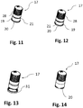
- the FIG. 11 shows a valve cap 17 according to the first embodiment in perspective view.
- the valve cap 17 has a coupling portion 19 and a cap portion 28, wherein the coupling portion 19 of the valve cap 17 and the counter coupling portion 13 of the union nut 14 have a positive and / or non-positive connection.
- the coupling portion 19 and the cap portion 28 are connected to a predetermined breaking point 29.
- the predetermined breaking point 29 is designed as a circumferentially radially inwardly oriented material weakening, in particular in the form of a circumferential groove.
- the valve cap 17 is preferably manufactured by means of a plastic injection molding process.
- the valve cap 17 may be made of metal.
- FIG. 12 shows a valve cap 17 with an alternative embodiment according to the first embodiment in perspective view.
- the valve cap 17 has a coupling portion 19 and a cap portion 28.
- a circumferentially radially outwardly aligned projection 20 is arranged, which forms a positive connection with the union nut 14.
- the coupling portion 19 and the cap portion 28 are connected to a predetermined breaking point 29.
- the predetermined breaking point 29 is designed as a material weakening 21 running around on the outer diameter in the form of a perforation.
- the valve cap 17 is preferably manufactured by means of a plastic injection molding process. It is also possible to form valve cap 17 made of metal.
- FIG. 13 shows a valve cap 17 with an alternative embodiment according to the first embodiment in perspective view.
- the valve cap 17 has a coupling portion 19 and a cap portion 28.
- the coupling portion 19 is formed as a circumferentially radially outwardly aligned ring 31.
- the ring 31 is formed as a separate component, wherein the ring 31 is shrinkable on the valve cap 17 and a form-fitting Connection with the union nut 14 forms.
- This embodiment requires no additional predetermined breaking point 29, since the ring 31 itself serves as a predetermined breaking element. It is also possible that the ring 31 is elastically formed or clamped between the inner surface of the nut 11.
- valve cap 17 is preferably manufactured by means of a plastic injection molding process. It is also possible to form valve cap 17 made of metal.
- FIG. 14 shows a valve cap 17 with an alternative embodiment according to the first embodiment in perspective view.
- the valve cap 17 has a coupling portion 19 and a cap portion 28, wherein the coupling portion 19 of the valve cap 17 and the counter coupling portion 13 of the union nut 14 have a positive and / or non-positive connection.
- the coupling portion 19 comprises a plurality of radially outwardly directed projections 20.
- the valve cap 17 may consist of a continuous circumferential radially outwardly directed projection 20.
- the projections 20 are made of the same material with the valve cap 17 by means of a plastic injection molding process. This embodiment requires no additional predetermined breaking point 29, since the projections themselves may be formed as a predetermined breaking element and have a positive connection with the union nut 14.
- the valve cap 17 is preferably manufactured by means of a plastic injection molding process. It is also possible to form valve cap 17 made of metal.
- FIG. 15 shows a valve cap 17 according to the second embodiment in perspective view.
- the valve cap 17 has a coupling portion 19 and a cap portion 28.
- On the coupling portion 19 is a circumferentially radially outward arranged aligned projection 20 which forms a positive connection with the union nut 14.
- the coupling portion 19 and the cap portion 28 are connected to a predetermined breaking point 29.
- the predetermined breaking point 29 is designed as a circumferentially radially inwardly oriented material weakening 21, in particular in the form of a circumferential groove.
- a latching connection is arranged on the outer diameter of the valve cap 17, which serves to connect the union nut 14 with the valve cap 17.
- the locking connection is designed such that the valve cap 17 both rotationally fixed, as well as connected in the axial direction with the union nut 14.
- the valve cap 17 and the union nut 14 can be mounted as a preassembled assembly with the tire valve 4.
- the valve cap 17 is preferably manufactured by means of a plastic injection molding process. It is also possible to form valve cap 17 made of metal.
- FIG. 16 shows a first assembly step in which the tire valve 4 is mounted with a preassembled mounting module to the rim 2, according to the second embodiment.
- the second embodiment differs from the first embodiment in that the delivery state is not pre-assembled with the valve cap 17 as in the first embodiment, but the union nut 14 is pre-assembled with the valve cap 17.
- This solution is intended for customers who do not have a special device for filling tires, which can fill the wheels with air through a gap between the tire and the rim 2 and thus would have to unscrew the valve cap 17 in the case.
- FIG. 17 shows a second assembly step, in which the preassembled mounting module (comprising the union nut 14 and valve cap 17) is screwed onto a threaded portion of the tire valve 4, according to the second embodiment.
- the assembly unit comprising union nut 14 and valve cap 17 is screwed onto the provided for the valve cap 17 threaded portion of the valve cap.
- the threaded portion of the valve cap is disposed in the region of the air inlet end 18.
- the coupling portion 19 of the valve cap 17 and the Counter coupling portion 13 of the union nut 14 at least temporarily coupled by a positive and / or non-positive connection.
- the Aufschraubmoment is transmitted to the tire valve 4, so that the tire valve 4 is taken.
- the tire pressure sensor is pressed against the rim 2 and fixed in this position by means of the fastening element 12.
- the positive and / or non-positive connection between the valve cap 17 and the union nut 14 is decoupled.
- the union nut 14 is further rotated and thus the tire valve 4 is firmly connected to the rim 2.
- the valve cap 17 can be removed and the tire can be inflated with air.
- the valve cap 17 is screwed onto the tire valve 4.
- stop 20 of the valve cap 17 may be formed in all embodiments as a deformation element, which is elastically or irreversibly deformable and has a positive or non-positive connection with the union nut 14.
Landscapes
- Engineering & Computer Science (AREA)
- Mechanical Engineering (AREA)
- Measuring Fluid Pressure (AREA)
Applications Claiming Priority (1)
| Application Number | Priority Date | Filing Date | Title |
|---|---|---|---|
| DE102017102415 | 2017-02-08 |
Publications (2)
| Publication Number | Publication Date |
|---|---|
| EP3360702A1 true EP3360702A1 (fr) | 2018-08-15 |
| EP3360702B1 EP3360702B1 (fr) | 2019-09-25 |
Family
ID=60673600
Family Applications (1)
| Application Number | Title | Priority Date | Filing Date |
|---|---|---|---|
| EP17207428.8A Active EP3360702B1 (fr) | 2017-02-08 | 2017-12-14 | Soupape du pneu pour un pneumatique d'un véhicule |
Country Status (2)
| Country | Link |
|---|---|
| EP (1) | EP3360702B1 (fr) |
| DE (1) | DE102017129950A1 (fr) |
Cited By (1)
| Publication number | Priority date | Publication date | Assignee | Title |
|---|---|---|---|---|
| CN113752759A (zh) * | 2020-06-05 | 2021-12-07 | 奇妙公司 | 配备有用于tpms传感器的调节系统的轮胎充气阀 |
Families Citing this family (1)
| Publication number | Priority date | Publication date | Assignee | Title |
|---|---|---|---|---|
| JP7280226B2 (ja) * | 2020-08-11 | 2023-05-23 | 太平洋工業株式会社 | 隔壁装着機器 |
Citations (4)
| Publication number | Priority date | Publication date | Assignee | Title |
|---|---|---|---|---|
| US1370474A (en) * | 1919-01-18 | 1921-03-01 | Newsom Valve Company | Dust-cap for pneumatic valves |
| EP0751017A2 (fr) | 1995-06-26 | 1997-01-02 | Alligator Ventilfabrik GmbH | Dispositif pour mesurer la pression d'un pneumatique d'un véhicule |
| EP1277601A2 (fr) | 2001-07-19 | 2003-01-22 | Alligator Ventilfabrik Gmbh | Dispositif pour mesurer la pression dans un pneumatique d'un véhicule |
| WO2014108926A1 (fr) | 2013-01-09 | 2014-07-17 | Wonder Spa | Valve métallique du type à serrage intérieur pour gonfler des pneus pouvant être associée à un transducteur de système de contrôle de pression de pneu |
-
2017
- 2017-12-14 EP EP17207428.8A patent/EP3360702B1/fr active Active
- 2017-12-14 DE DE102017129950.5A patent/DE102017129950A1/de not_active Withdrawn
Patent Citations (4)
| Publication number | Priority date | Publication date | Assignee | Title |
|---|---|---|---|---|
| US1370474A (en) * | 1919-01-18 | 1921-03-01 | Newsom Valve Company | Dust-cap for pneumatic valves |
| EP0751017A2 (fr) | 1995-06-26 | 1997-01-02 | Alligator Ventilfabrik GmbH | Dispositif pour mesurer la pression d'un pneumatique d'un véhicule |
| EP1277601A2 (fr) | 2001-07-19 | 2003-01-22 | Alligator Ventilfabrik Gmbh | Dispositif pour mesurer la pression dans un pneumatique d'un véhicule |
| WO2014108926A1 (fr) | 2013-01-09 | 2014-07-17 | Wonder Spa | Valve métallique du type à serrage intérieur pour gonfler des pneus pouvant être associée à un transducteur de système de contrôle de pression de pneu |
Cited By (2)
| Publication number | Priority date | Publication date | Assignee | Title |
|---|---|---|---|---|
| CN113752759A (zh) * | 2020-06-05 | 2021-12-07 | 奇妙公司 | 配备有用于tpms传感器的调节系统的轮胎充气阀 |
| CN113752759B (zh) * | 2020-06-05 | 2025-07-15 | 奇妙公司 | 配备有用于tpms传感器的调节系统的轮胎充气阀 |
Also Published As
| Publication number | Publication date |
|---|---|
| EP3360702B1 (fr) | 2019-09-25 |
| DE102017129950A1 (de) | 2018-08-09 |
Similar Documents
| Publication | Publication Date | Title |
|---|---|---|
| EP3303016B1 (fr) | Valve de pneumatique pour pneumatique de véhicule | |
| DE69513266T2 (de) | Verriegelungsvorrichtung für eine Rohrverbindung | |
| EP3173675B1 (fr) | Raccord de tuyau | |
| EP2614263A1 (fr) | Assemblage à serrage sans collier | |
| EP0600432A1 (fr) | Tuyauterie ou tuyauterie flexible pour le transport d'un fluide | |
| EP3360702B1 (fr) | Soupape du pneu pour un pneumatique d'un véhicule | |
| EP3766710B1 (fr) | Dispositif de mesure d'une pression d'un pneu de deux roues, en particulier d'un pneu de bicyclette | |
| EP3237238A1 (fr) | Élément de fixation pour capteur de pression de pneumatiques, système de valve et système de contrôle de la pression de pneumatiques pour un véhicule | |
| EP3313675B1 (fr) | Systeme de controle de pression de pneu pour un vehicule automobile | |
| EP0688994A1 (fr) | Raccord de connexion pour un corps de soupape en plastique | |
| WO2000061416A1 (fr) | Servofrein pneumatique | |
| EP2064454B1 (fr) | Dispositif de fixation | |
| DE102008027123A1 (de) | Vorrichtung zum Befestigen eines Bauteiles, insbesondere einer Haltekonsole für Nebenaggregate eines Fahrzeuges, insbesondere eines Nutz- oder Kraftfahrzeuges | |
| EP2095003B1 (fr) | Bloc de raccordement pour conduites de fluide | |
| EP3566815B1 (fr) | Dispositif de fixation permettant de tendre des moyens de fixation au moins comportant une sécurité antitorsion | |
| DE19643751A1 (de) | Meßgerät | |
| EP1577598B1 (fr) | Elément de raccord, adapté en particulier au ravitaillement des véhicules fonctionnant au gaz naturel | |
| EP3138703A1 (fr) | Systeme de controle de pression de pneu pour un vehicule automobile | |
| DE112008000586B4 (de) | Anschlussvorrichtung für Medienleitungen | |
| EP1877241B1 (fr) | Dispositif pour etancheifier et gonfler des objets gonflables | |
| EP3135509B1 (fr) | Systeme de controle de pression de pneu pour un vehicule automobile | |
| DE4440240C1 (de) | Radbefestigung für Fahrzeuge | |
| WO2016023679A1 (fr) | Barre d'accouplement ou de direction pour véhicule | |
| DE102009051025A1 (de) | Vorrichtung und Verfahren zum Demontieren eines Anschlussteiles | |
| DE202005005501U1 (de) | Schnellspannmutter |
Legal Events
| Date | Code | Title | Description |
|---|---|---|---|
| PUAI | Public reference made under article 153(3) epc to a published international application that has entered the european phase |
Free format text: ORIGINAL CODE: 0009012 |
|
| STAA | Information on the status of an ep patent application or granted ep patent |
Free format text: STATUS: THE APPLICATION HAS BEEN PUBLISHED |
|
| AK | Designated contracting states |
Kind code of ref document: A1 Designated state(s): AL AT BE BG CH CY CZ DE DK EE ES FI FR GB GR HR HU IE IS IT LI LT LU LV MC MK MT NL NO PL PT RO RS SE SI SK SM TR |
|
| AX | Request for extension of the european patent |
Extension state: BA ME |
|
| STAA | Information on the status of an ep patent application or granted ep patent |
Free format text: STATUS: REQUEST FOR EXAMINATION WAS MADE |
|
| 17P | Request for examination filed |
Effective date: 20180903 |
|
| RBV | Designated contracting states (corrected) |
Designated state(s): AL AT BE BG CH CY CZ DE DK EE ES FI FR GB GR HR HU IE IS IT LI LT LU LV MC MK MT NL NO PL PT RO RS SE SI SK SM TR |
|
| RIC1 | Information provided on ipc code assigned before grant |
Ipc: B60C 23/04 20060101AFI20181207BHEP Ipc: B60C 29/06 20060101ALI20181207BHEP |
|
| GRAP | Despatch of communication of intention to grant a patent |
Free format text: ORIGINAL CODE: EPIDOSNIGR1 |
|
| STAA | Information on the status of an ep patent application or granted ep patent |
Free format text: STATUS: GRANT OF PATENT IS INTENDED |
|
| INTG | Intention to grant announced |
Effective date: 20190118 |
|
| GRAS | Grant fee paid |
Free format text: ORIGINAL CODE: EPIDOSNIGR3 |
|
| GRAA | (expected) grant |
Free format text: ORIGINAL CODE: 0009210 |
|
| STAA | Information on the status of an ep patent application or granted ep patent |
Free format text: STATUS: THE PATENT HAS BEEN GRANTED |
|
| AK | Designated contracting states |
Kind code of ref document: B1 Designated state(s): AL AT BE BG CH CY CZ DE DK EE ES FI FR GB GR HR HU IE IS IT LI LT LU LV MC MK MT NL NO PL PT RO RS SE SI SK SM TR |
|
| REG | Reference to a national code |
Ref country code: GB Ref legal event code: FG4D Free format text: NOT ENGLISH |
|
| REG | Reference to a national code |
Ref country code: CH Ref legal event code: EP |
|
| REG | Reference to a national code |
Ref country code: DE Ref legal event code: R096 Ref document number: 502017002402 Country of ref document: DE |
|
| REG | Reference to a national code |
Ref country code: AT Ref legal event code: REF Ref document number: 1183458 Country of ref document: AT Kind code of ref document: T Effective date: 20191015 |
|
| REG | Reference to a national code |
Ref country code: IE Ref legal event code: FG4D Free format text: LANGUAGE OF EP DOCUMENT: GERMAN |
|
| REG | Reference to a national code |
Ref country code: NL Ref legal event code: MP Effective date: 20190925 |
|
| PG25 | Lapsed in a contracting state [announced via postgrant information from national office to epo] |
Ref country code: NO Free format text: LAPSE BECAUSE OF FAILURE TO SUBMIT A TRANSLATION OF THE DESCRIPTION OR TO PAY THE FEE WITHIN THE PRESCRIBED TIME-LIMIT Effective date: 20191225 Ref country code: SE Free format text: LAPSE BECAUSE OF FAILURE TO SUBMIT A TRANSLATION OF THE DESCRIPTION OR TO PAY THE FEE WITHIN THE PRESCRIBED TIME-LIMIT Effective date: 20190925 Ref country code: HR Free format text: LAPSE BECAUSE OF FAILURE TO SUBMIT A TRANSLATION OF THE DESCRIPTION OR TO PAY THE FEE WITHIN THE PRESCRIBED TIME-LIMIT Effective date: 20190925 Ref country code: LT Free format text: LAPSE BECAUSE OF FAILURE TO SUBMIT A TRANSLATION OF THE DESCRIPTION OR TO PAY THE FEE WITHIN THE PRESCRIBED TIME-LIMIT Effective date: 20190925 Ref country code: BG Free format text: LAPSE BECAUSE OF FAILURE TO SUBMIT A TRANSLATION OF THE DESCRIPTION OR TO PAY THE FEE WITHIN THE PRESCRIBED TIME-LIMIT Effective date: 20191225 Ref country code: FI Free format text: LAPSE BECAUSE OF FAILURE TO SUBMIT A TRANSLATION OF THE DESCRIPTION OR TO PAY THE FEE WITHIN THE PRESCRIBED TIME-LIMIT Effective date: 20190925 |
|
| REG | Reference to a national code |
Ref country code: LT Ref legal event code: MG4D |
|
| PG25 | Lapsed in a contracting state [announced via postgrant information from national office to epo] |
Ref country code: GR Free format text: LAPSE BECAUSE OF FAILURE TO SUBMIT A TRANSLATION OF THE DESCRIPTION OR TO PAY THE FEE WITHIN THE PRESCRIBED TIME-LIMIT Effective date: 20191226 Ref country code: LV Free format text: LAPSE BECAUSE OF FAILURE TO SUBMIT A TRANSLATION OF THE DESCRIPTION OR TO PAY THE FEE WITHIN THE PRESCRIBED TIME-LIMIT Effective date: 20190925 Ref country code: RS Free format text: LAPSE BECAUSE OF FAILURE TO SUBMIT A TRANSLATION OF THE DESCRIPTION OR TO PAY THE FEE WITHIN THE PRESCRIBED TIME-LIMIT Effective date: 20190925 |
|
| PG25 | Lapsed in a contracting state [announced via postgrant information from national office to epo] |
Ref country code: AL Free format text: LAPSE BECAUSE OF FAILURE TO SUBMIT A TRANSLATION OF THE DESCRIPTION OR TO PAY THE FEE WITHIN THE PRESCRIBED TIME-LIMIT Effective date: 20190925 Ref country code: ES Free format text: LAPSE BECAUSE OF FAILURE TO SUBMIT A TRANSLATION OF THE DESCRIPTION OR TO PAY THE FEE WITHIN THE PRESCRIBED TIME-LIMIT Effective date: 20190925 Ref country code: IT Free format text: LAPSE BECAUSE OF FAILURE TO SUBMIT A TRANSLATION OF THE DESCRIPTION OR TO PAY THE FEE WITHIN THE PRESCRIBED TIME-LIMIT Effective date: 20190925 Ref country code: EE Free format text: LAPSE BECAUSE OF FAILURE TO SUBMIT A TRANSLATION OF THE DESCRIPTION OR TO PAY THE FEE WITHIN THE PRESCRIBED TIME-LIMIT Effective date: 20190925 Ref country code: RO Free format text: LAPSE BECAUSE OF FAILURE TO SUBMIT A TRANSLATION OF THE DESCRIPTION OR TO PAY THE FEE WITHIN THE PRESCRIBED TIME-LIMIT Effective date: 20190925 Ref country code: NL Free format text: LAPSE BECAUSE OF FAILURE TO SUBMIT A TRANSLATION OF THE DESCRIPTION OR TO PAY THE FEE WITHIN THE PRESCRIBED TIME-LIMIT Effective date: 20190925 Ref country code: PL Free format text: LAPSE BECAUSE OF FAILURE TO SUBMIT A TRANSLATION OF THE DESCRIPTION OR TO PAY THE FEE WITHIN THE PRESCRIBED TIME-LIMIT Effective date: 20190925 Ref country code: PT Free format text: LAPSE BECAUSE OF FAILURE TO SUBMIT A TRANSLATION OF THE DESCRIPTION OR TO PAY THE FEE WITHIN THE PRESCRIBED TIME-LIMIT Effective date: 20200127 |
|
| PG25 | Lapsed in a contracting state [announced via postgrant information from national office to epo] |
Ref country code: IS Free format text: LAPSE BECAUSE OF FAILURE TO SUBMIT A TRANSLATION OF THE DESCRIPTION OR TO PAY THE FEE WITHIN THE PRESCRIBED TIME-LIMIT Effective date: 20200224 Ref country code: SK Free format text: LAPSE BECAUSE OF FAILURE TO SUBMIT A TRANSLATION OF THE DESCRIPTION OR TO PAY THE FEE WITHIN THE PRESCRIBED TIME-LIMIT Effective date: 20190925 Ref country code: CZ Free format text: LAPSE BECAUSE OF FAILURE TO SUBMIT A TRANSLATION OF THE DESCRIPTION OR TO PAY THE FEE WITHIN THE PRESCRIBED TIME-LIMIT Effective date: 20190925 Ref country code: SM Free format text: LAPSE BECAUSE OF FAILURE TO SUBMIT A TRANSLATION OF THE DESCRIPTION OR TO PAY THE FEE WITHIN THE PRESCRIBED TIME-LIMIT Effective date: 20190925 |
|
| REG | Reference to a national code |
Ref country code: DE Ref legal event code: R097 Ref document number: 502017002402 Country of ref document: DE |
|
| PG2D | Information on lapse in contracting state deleted |
Ref country code: IS |
|
| PG25 | Lapsed in a contracting state [announced via postgrant information from national office to epo] |
Ref country code: DK Free format text: LAPSE BECAUSE OF FAILURE TO SUBMIT A TRANSLATION OF THE DESCRIPTION OR TO PAY THE FEE WITHIN THE PRESCRIBED TIME-LIMIT Effective date: 20190925 Ref country code: IS Free format text: LAPSE BECAUSE OF FAILURE TO SUBMIT A TRANSLATION OF THE DESCRIPTION OR TO PAY THE FEE WITHIN THE PRESCRIBED TIME-LIMIT Effective date: 20200126 |
|
| PLBE | No opposition filed within time limit |
Free format text: ORIGINAL CODE: 0009261 |
|
| STAA | Information on the status of an ep patent application or granted ep patent |
Free format text: STATUS: NO OPPOSITION FILED WITHIN TIME LIMIT |
|
| REG | Reference to a national code |
Ref country code: BE Ref legal event code: MM Effective date: 20191231 |
|
| PG25 | Lapsed in a contracting state [announced via postgrant information from national office to epo] |
Ref country code: MC Free format text: LAPSE BECAUSE OF FAILURE TO SUBMIT A TRANSLATION OF THE DESCRIPTION OR TO PAY THE FEE WITHIN THE PRESCRIBED TIME-LIMIT Effective date: 20190925 |
|
| 26N | No opposition filed |
Effective date: 20200626 |
|
| PG25 | Lapsed in a contracting state [announced via postgrant information from national office to epo] |
Ref country code: IE Free format text: LAPSE BECAUSE OF NON-PAYMENT OF DUE FEES Effective date: 20191214 Ref country code: FR Free format text: LAPSE BECAUSE OF NON-PAYMENT OF DUE FEES Effective date: 20191231 Ref country code: LU Free format text: LAPSE BECAUSE OF NON-PAYMENT OF DUE FEES Effective date: 20191214 |
|
| PG25 | Lapsed in a contracting state [announced via postgrant information from national office to epo] |
Ref country code: SI Free format text: LAPSE BECAUSE OF FAILURE TO SUBMIT A TRANSLATION OF THE DESCRIPTION OR TO PAY THE FEE WITHIN THE PRESCRIBED TIME-LIMIT Effective date: 20190925 Ref country code: BE Free format text: LAPSE BECAUSE OF NON-PAYMENT OF DUE FEES Effective date: 20191231 |
|
| PG25 | Lapsed in a contracting state [announced via postgrant information from national office to epo] |
Ref country code: CY Free format text: LAPSE BECAUSE OF FAILURE TO SUBMIT A TRANSLATION OF THE DESCRIPTION OR TO PAY THE FEE WITHIN THE PRESCRIBED TIME-LIMIT Effective date: 20190925 |
|
| REG | Reference to a national code |
Ref country code: DE Ref legal event code: R081 Ref document number: 502017002402 Country of ref document: DE Owner name: HUF BAOLONG ELECTRONICS BRETTEN GMBH, DE Free format text: FORMER OWNER: HUF HUELSBECK & FUERST GMBH & CO. KG, 42551 VELBERT, DE |
|
| PG25 | Lapsed in a contracting state [announced via postgrant information from national office to epo] |
Ref country code: HU Free format text: LAPSE BECAUSE OF FAILURE TO SUBMIT A TRANSLATION OF THE DESCRIPTION OR TO PAY THE FEE WITHIN THE PRESCRIBED TIME-LIMIT; INVALID AB INITIO Effective date: 20171214 Ref country code: MT Free format text: LAPSE BECAUSE OF FAILURE TO SUBMIT A TRANSLATION OF THE DESCRIPTION OR TO PAY THE FEE WITHIN THE PRESCRIBED TIME-LIMIT Effective date: 20190925 |
|
| REG | Reference to a national code |
Ref country code: CH Ref legal event code: PL |
|
| PG25 | Lapsed in a contracting state [announced via postgrant information from national office to epo] |
Ref country code: CH Free format text: LAPSE BECAUSE OF NON-PAYMENT OF DUE FEES Effective date: 20201231 Ref country code: LI Free format text: LAPSE BECAUSE OF NON-PAYMENT OF DUE FEES Effective date: 20201231 |
|
| PG25 | Lapsed in a contracting state [announced via postgrant information from national office to epo] |
Ref country code: TR Free format text: LAPSE BECAUSE OF FAILURE TO SUBMIT A TRANSLATION OF THE DESCRIPTION OR TO PAY THE FEE WITHIN THE PRESCRIBED TIME-LIMIT Effective date: 20190925 |
|
| PG25 | Lapsed in a contracting state [announced via postgrant information from national office to epo] |
Ref country code: MK Free format text: LAPSE BECAUSE OF FAILURE TO SUBMIT A TRANSLATION OF THE DESCRIPTION OR TO PAY THE FEE WITHIN THE PRESCRIBED TIME-LIMIT Effective date: 20190925 |
|
| GBPC | Gb: european patent ceased through non-payment of renewal fee |
Effective date: 20211214 |
|
| PG25 | Lapsed in a contracting state [announced via postgrant information from national office to epo] |
Ref country code: GB Free format text: LAPSE BECAUSE OF NON-PAYMENT OF DUE FEES Effective date: 20211214 |
|
| REG | Reference to a national code |
Ref country code: AT Ref legal event code: MM01 Ref document number: 1183458 Country of ref document: AT Kind code of ref document: T Effective date: 20221214 |
|
| PG25 | Lapsed in a contracting state [announced via postgrant information from national office to epo] |
Ref country code: AT Free format text: LAPSE BECAUSE OF NON-PAYMENT OF DUE FEES Effective date: 20221214 |
|
| PG25 | Lapsed in a contracting state [announced via postgrant information from national office to epo] |
Ref country code: AT Free format text: LAPSE BECAUSE OF NON-PAYMENT OF DUE FEES Effective date: 20221214 |
|
| PGFP | Annual fee paid to national office [announced via postgrant information from national office to epo] |
Ref country code: DE Payment date: 20251222 Year of fee payment: 9 |
|
| PGFP | Annual fee paid to national office [announced via postgrant information from national office to epo] |
Ref country code: AT Payment date: 20260410 Year of fee payment: 5 |