EP3360711B1 - Nutzfahrzeug - Google Patents
Nutzfahrzeug Download PDFInfo
- Publication number
- EP3360711B1 EP3360711B1 EP16869371.1A EP16869371A EP3360711B1 EP 3360711 B1 EP3360711 B1 EP 3360711B1 EP 16869371 A EP16869371 A EP 16869371A EP 3360711 B1 EP3360711 B1 EP 3360711B1
- Authority
- EP
- European Patent Office
- Prior art keywords
- shroud
- blower unit
- cooling unit
- fixation
- movable
- Prior art date
- Legal status (The legal status is an assumption and is not a legal conclusion. Google has not performed a legal analysis and makes no representation as to the accuracy of the status listed.)
- Active
Links
Images



Classifications
-
- B—PERFORMING OPERATIONS; TRANSPORTING
- B60—VEHICLES IN GENERAL
- B60K—ARRANGEMENT OR MOUNTING OF PROPULSION UNITS OR OF TRANSMISSIONS IN VEHICLES; ARRANGEMENT OR MOUNTING OF PLURAL DIVERSE PRIME-MOVERS IN VEHICLES; AUXILIARY DRIVES FOR VEHICLES; INSTRUMENTATION OR DASHBOARDS FOR VEHICLES; ARRANGEMENTS IN CONNECTION WITH COOLING, AIR INTAKE, GAS EXHAUST OR FUEL SUPPLY OF PROPULSION UNITS IN VEHICLES
- B60K11/00—Arrangement in connection with cooling of propulsion units
-
- B—PERFORMING OPERATIONS; TRANSPORTING
- B60—VEHICLES IN GENERAL
- B60K—ARRANGEMENT OR MOUNTING OF PROPULSION UNITS OR OF TRANSMISSIONS IN VEHICLES; ARRANGEMENT OR MOUNTING OF PLURAL DIVERSE PRIME-MOVERS IN VEHICLES; AUXILIARY DRIVES FOR VEHICLES; INSTRUMENTATION OR DASHBOARDS FOR VEHICLES; ARRANGEMENTS IN CONNECTION WITH COOLING, AIR INTAKE, GAS EXHAUST OR FUEL SUPPLY OF PROPULSION UNITS IN VEHICLES
- B60K11/00—Arrangement in connection with cooling of propulsion units
- B60K11/02—Arrangement in connection with cooling of propulsion units with liquid cooling
-
- B—PERFORMING OPERATIONS; TRANSPORTING
- B60—VEHICLES IN GENERAL
- B60K—ARRANGEMENT OR MOUNTING OF PROPULSION UNITS OR OF TRANSMISSIONS IN VEHICLES; ARRANGEMENT OR MOUNTING OF PLURAL DIVERSE PRIME-MOVERS IN VEHICLES; AUXILIARY DRIVES FOR VEHICLES; INSTRUMENTATION OR DASHBOARDS FOR VEHICLES; ARRANGEMENTS IN CONNECTION WITH COOLING, AIR INTAKE, GAS EXHAUST OR FUEL SUPPLY OF PROPULSION UNITS IN VEHICLES
- B60K11/00—Arrangement in connection with cooling of propulsion units
- B60K11/02—Arrangement in connection with cooling of propulsion units with liquid cooling
- B60K11/04—Arrangement or mounting of radiators, radiator shutters, or radiator blinds
-
- E—FIXED CONSTRUCTIONS
- E02—HYDRAULIC ENGINEERING; FOUNDATIONS; SOIL SHIFTING
- E02F—DREDGING; SOIL-SHIFTING
- E02F9/00—Component parts of dredgers or soil-shifting machines, not restricted to one of the kinds covered by groups E02F3/00 - E02F7/00
- E02F9/08—Superstructures; Supports for superstructures
- E02F9/0808—Improving mounting or assembling, e.g. frame elements, disposition of all the components on the superstructures
-
- E—FIXED CONSTRUCTIONS
- E02—HYDRAULIC ENGINEERING; FOUNDATIONS; SOIL SHIFTING
- E02F—DREDGING; SOIL-SHIFTING
- E02F9/00—Component parts of dredgers or soil-shifting machines, not restricted to one of the kinds covered by groups E02F3/00 - E02F7/00
- E02F9/08—Superstructures; Supports for superstructures
- E02F9/0833—Improving access, e.g. for maintenance, steps for improving driver's access, handrails
-
- E—FIXED CONSTRUCTIONS
- E02—HYDRAULIC ENGINEERING; FOUNDATIONS; SOIL SHIFTING
- E02F—DREDGING; SOIL-SHIFTING
- E02F9/00—Component parts of dredgers or soil-shifting machines, not restricted to one of the kinds covered by groups E02F3/00 - E02F7/00
- E02F9/08—Superstructures; Supports for superstructures
- E02F9/0858—Arrangement of component parts installed on superstructures not otherwise provided for, e.g. electric components, fenders, air-conditioning units
- E02F9/0866—Engine compartment, e.g. heat exchangers, exhaust filters, cooling devices, silencers, mufflers, position of hydraulic pumps in the engine compartment
-
- E—FIXED CONSTRUCTIONS
- E02—HYDRAULIC ENGINEERING; FOUNDATIONS; SOIL SHIFTING
- E02F—DREDGING; SOIL-SHIFTING
- E02F9/00—Component parts of dredgers or soil-shifting machines, not restricted to one of the kinds covered by groups E02F3/00 - E02F7/00
- E02F9/08—Superstructures; Supports for superstructures
- E02F9/0858—Arrangement of component parts installed on superstructures not otherwise provided for, e.g. electric components, fenders, air-conditioning units
- E02F9/0891—Lids or bonnets or doors or details thereof
-
- B—PERFORMING OPERATIONS; TRANSPORTING
- B60—VEHICLES IN GENERAL
- B60Y—INDEXING SCHEME RELATING TO ASPECTS CROSS-CUTTING VEHICLE TECHNOLOGY
- B60Y2200/00—Type of vehicle
- B60Y2200/40—Special vehicles
-
- B—PERFORMING OPERATIONS; TRANSPORTING
- B60—VEHICLES IN GENERAL
- B60Y—INDEXING SCHEME RELATING TO ASPECTS CROSS-CUTTING VEHICLE TECHNOLOGY
- B60Y2200/00—Type of vehicle
- B60Y2200/40—Special vehicles
- B60Y2200/41—Construction vehicles, e.g. graders, excavators
-
- B—PERFORMING OPERATIONS; TRANSPORTING
- B60—VEHICLES IN GENERAL
- B60Y—INDEXING SCHEME RELATING TO ASPECTS CROSS-CUTTING VEHICLE TECHNOLOGY
- B60Y2200/00—Type of vehicle
- B60Y2200/40—Special vehicles
- B60Y2200/41—Construction vehicles, e.g. graders, excavators
- B60Y2200/415—Wheel loaders
-
- E—FIXED CONSTRUCTIONS
- E02—HYDRAULIC ENGINEERING; FOUNDATIONS; SOIL SHIFTING
- E02F—DREDGING; SOIL-SHIFTING
- E02F3/00—Dredgers; Soil-shifting machines
- E02F3/04—Dredgers; Soil-shifting machines mechanically-driven
- E02F3/28—Dredgers; Soil-shifting machines mechanically-driven with digging tools mounted on a dipper- or bucket-arm, i.e. there is either one arm or a pair of arms, e.g. dippers, buckets
- E02F3/283—Dredgers; Soil-shifting machines mechanically-driven with digging tools mounted on a dipper- or bucket-arm, i.e. there is either one arm or a pair of arms, e.g. dippers, buckets with a single arm pivoted directly on the chassis
Definitions
- WO 2004/099581 A1 US 2015/017901 A1 and US 2003/230904 A1 disclose work vehicles having a rotatable fan assembly provided at a rear thereof.
- the fan assemblies are rotatable about a vertical axis and comprise a shroud rotated together with the fan, respectively.
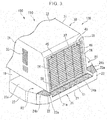
- the top cover 32 has a panel shape which extends in the forward-backward direction and the horizontal direction. Both ends of the top cover 32 in the width direction are connected to the upper ends of the pair of side covers 31 in the forward-backward direction.
- the radiator, the oil cooler, and the after-cooler may be provided so as to be lifted out upward with respect to the outer frame.
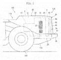
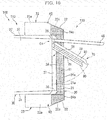
- a movement region (a movement range of the blower unit 70) of the blower unit 70 including a rotation locus between the closed position and the open position of the blower unit 70 does not interfere with the vehicle rear portion 130 in which the grille 46 is open or other configurations.
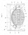
- the lower end of the blower unit 70 passes through a portion above the upper surface 21a in the bumper center portion 21 configuring the rear passage R1. That is, the movement region of the blower unit 70 passes through the portion above the upper surface 21a along the upper surface 21a without interfering with the upper surface 21a of the bumper center portion 21 configuring the rear passage R1. Accordingly, as shown in FIG. 10 , the movement region of the blower unit 70 in a plan view when viewed from above overlaps the rear passage R1.
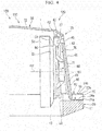
- the cooling unit 50 or the fixation shroud 60 since the upper end of the cooling unit 50 or the fixation shroud 60 is positioned above the rear lights 45 or the lower end of the upper frame 42 of the support frame 40, the cooling unit 50 or the fixation shroud 60 interferes with the rear lights 45 or the support frame 40. Since the blower unit 70 does not interfere with the structures such as the rear lights 45 or the support frame 40, it is possible to transfer the blower unit 70 from the closed position to the open position via the opening portion 35 of the vehicle rear portion 130. Accordingly, as described above, it is possible to secure workability with respect to the movable shroud 90, the fixation shroud 60, and the rear surface 51 of the cooling unit 50.
- the rear lights 45 or the upper frame 42 of the support frame 40 is exemplified as the upper structure positioned above the blower unit positioned at the closed position in the heat exchange room T.
- the present invention is not limited to this, and other upper structures may be positioned. In this case, it is possible to rotate the blower unit 70 between the closed position and the open position as long as the upper structure does not interfere with the movement region of the blower unit 70.
Landscapes
- Engineering & Computer Science (AREA)
- Mining & Mineral Resources (AREA)
- Civil Engineering (AREA)
- General Engineering & Computer Science (AREA)
- Structural Engineering (AREA)
- Chemical & Material Sciences (AREA)
- Combustion & Propulsion (AREA)
- Transportation (AREA)
- Mechanical Engineering (AREA)
- Cooling, Air Intake And Gas Exhaust, And Fuel Tank Arrangements In Propulsion Units (AREA)
- Component Parts Of Construction Machinery (AREA)
- Body Structure For Vehicles (AREA)
Claims (10)
- Arbeitsfahrzeug, das umfasst:eine Fahrzeugkarosserie (110), die einen Wärmeaustauschraum (T), in dem ein Öffnungsabschnitt (35) ausgebildet ist, der einer Rückseite der Fahrzeugkarosserie (110) zugewandt ist, und einen hinteren Umgang (R1) umfasst, der sich in einer Breitenrichtung hinter dem Öffnungsabschnitt (35) an einem unteren Randabschnitt (38) des Öffnungsabschnitts (35) entlang erstreckt;eine Kühl-Einheit (50), die in dem Wärmeaustauschraum (T) vorhanden ist und eine der Rückseite zugewandte hintere Fläche (51) einschließt;eine Gebläse-Einheit (70), die einen rotierend angetriebenen Lüfter (80) sowie eine bewegliche Verkleidung (90) enthält, die den Lüfter (80) von einer Außenumfangsseite her abdeckt, und die so gelagert ist, dass sie in Bezug auf die Fahrzeugkarosserie (110) so bewegt werden kann, dass ein Bewegungsbereich der Gebläse-Einheit (70) zwischen einer geschlossenen Position, in der die Gebläse-Einheit (70) der hinteren Fläche (51) der Kühl-Einheit (50) zugewandt ist, und einer offenen Position, in der die Gebläse-Einheit (70) die hintere Fläche (51) der Kühl-Einheit (50) freilegt, in einer Draufsicht den hinteren Umgang (R1) überlappt; sowieeine feste Verkleidung (60), die an der hinteren Fläche (51) der Kühl-Einheit (50) in dem Wärmeaustauschraum (T) vorhanden ist und die zusammen mit der in der geschlossenen Position befindlichen beweglichen Verkleidung (90) der Kühl-Einheit (50) einen Strömungsweg bildet, über den Luft von der hinteren Fläche (51) der Kühl-Einheit (50) zu dem Lüfter (80) eingeleitet wird,dadurch gekennzeichnet, dassdie feste Verkleidung (60) eine Ringform hat und einen Absatzabschnitt (62) der festen Seite sowie einen abgeschrägten Abschnitt (63) enthält,der Absatzabschnitt (62) der festen Seite eine flache Plattenform hat, die eine Fläche im rechten Winkel zu einer Längsrichtung der Fahrzeugkarosserie (110) aufweist,der abgeschrägte Abschnitt (63) mit dem Absatzabschnitt (62) der festen Seite verbunden ist und eine Form hat, bei der eine Strömungsweg-Querschnittsfläche von einem Endabschnitt an einer Innenseite in einer radialen Richtung des Absatzabschnitts (62) der festen Seite zu der Rückseite hin abnimmt, unddie bewegliche Verkleidung (90) einen Verbindungs-Röhrenabschnitt (91) aufweist, der eine Röhrenform hat und sich so erstreckt, dass er eine einheitliche Strömungsweg-Querschnittsfläche von einem vorderen Ende des Verbindungs-Röhrenabschnitts (91) zu der Rückseite hin aufweist, und das vordere Ende des Verbindungs-Röhrenabschnitts (91) mit dem Absatzabschnitt (62) der festen Seite in Kontakt kommt.
- Arbeitsfahrzeug nach Anspruch 1,
wobei die Gebläse-Einheit (70) so gelagert ist, dass sie sich in Bezug auf die Fahrzeugkarosserie (110) drehbar um eine Drehachse (O1) herum bewegt, die sich in einer vertikalen Richtung an einer Seite der Fahrzeugkarosserie (110) in der Breitenrichtung erstreckt. - Arbeitsfahrzeug nach Anspruch 1,
wobei die bewegliche Verkleidung (90) eine Ringform hat, die das Gebläse (80) von der Außenumfangsseite her abdeckt und mit der festen Verkleidung (60) von der Rückseite her verbunden ist, wenn sich die Gebläse-Einheit (70) in der geschlossenen Position befindet. - Arbeitsfahrzeug nach Anspruch 3,
wobei eine Öffnungsfläche der festen Verkleidung (60), von der Rückseite aus gesehen, größer ist als eine Öffnungsfläche der beweglichen Verkleidung (90), von der Rückseite aus gesehen. - Arbeitsfahrzeug nach einem der Ansprüche 1 bis 4, das des Weiteren umfasst:
ein Dichtungselement (94), das bewirkt, dass die bewegliche Verkleidung (90) und die feste Verkleidung (60) in engem Kontakt miteinander sind, wenn sich die Gebläse-Einheit (70) in der geschlossenen Position befindet. - Arbeitsfahrzeug nach einem der Ansprüche 1 bis 5,
wobei ein unteres Ende der Kühl-Einheit (50) und ein unteres Ende der festen Verkleidung (60) unterhalb des unteren Randabschnitts (38) des Öffnungsabschnitts (35) positioniert sind und ein unteres Ende der Gebläse-Einheit (70) oberhalb des unteren Randabschnitts (38) des Öffnungsabschnitts (35) positioniert ist. - Arbeitsfahrzeug nach einem der Ansprüche 1 bis 6,
wobei die Fahrzeugkarosserie (110) eine obere Struktur (45) oberhalb der Gebläse-Einheit (70) enthält, die sich in der geschlossenen Position in dem Wärmeaustauschraum (T) befindet, und
obere Enden der Kühl-Einheit (50) und der festen Verkleidung (60) oberhalb eines unteren Endes der oberen Struktur (45) positioniert sind. - Arbeitsfahrzeug nach einem der Ansprüche 1 bis 7,
wobei die Fahrzeugkarosserie (110) enthält:ein Paar hinterer Rahmen (10), die sich in Längsrichtung in Abständen zwischen ihnen in einer Breitenrichtung erstrecken;eine äußere Abdeckung (30), die oberhalb der paarigen hinteren Rahmen (10) vorhanden ist und wobei der Wärmeaustauschraum (T) im Inneren der äußeren Abdeckung (30) ausgebildet ist; sowieeine Stoßstange (20), die so eingerichtet ist, dass sie sich in der Breitenrichtung über die paarigen hinteren Rahmen (10) an einer hinteren Seite der hinteren Rahmen (10) erstreckt, eine obere Fläche (21a) enthält, die den hinteren Umgang (R1) bildet, und zusammen mit der äußeren Abdeckung (30) den Öffnungs-Abschnitt (35) abteilt und bildet. - Arbeitsfahrzeug nach einem der Ansprüche 1 bis 8,
wobei, wenn sich die Gebläse-Einheit (70) in der geschlossenen Position befindet, das vordere Ende des Verbindungs-Röhrenabschnitts (91) der beweglichen Verkleidung (90) vor einem hinteren Endabschnitt des abgeschrägten Abschnitts (63) positioniert ist. - Arbeitsfahrzeug nach einem der Ansprüche 1 bis 9,
wobei in einem Zustand, in dem ein vorderes Ende der beweglichen Verkleidung (90) an der festen Verkleidung (60) anliegt, ein Abschnitt des abgeschrägten Abschnitts (63), der der Abschnitt an der Seite des hinteren Endes der festen Abdeckung (60) ist, in den Innenraum des Verbindungs-Röhrenabschnitts (91) der beweglichen Verkleidung (90) eingeführt ist.
Applications Claiming Priority (1)
| Application Number | Priority Date | Filing Date | Title |
|---|---|---|---|
| PCT/JP2016/089071 WO2018123006A1 (ja) | 2016-12-28 | 2016-12-28 | 作業車両 |
Publications (3)
| Publication Number | Publication Date |
|---|---|
| EP3360711A1 EP3360711A1 (de) | 2018-08-15 |
| EP3360711A4 EP3360711A4 (de) | 2019-04-03 |
| EP3360711B1 true EP3360711B1 (de) | 2020-07-15 |
Family
ID=62707107
Family Applications (1)
| Application Number | Title | Priority Date | Filing Date |
|---|---|---|---|
| EP16869371.1A Active EP3360711B1 (de) | 2016-12-28 | 2016-12-28 | Nutzfahrzeug |
Country Status (5)
| Country | Link |
|---|---|
| US (1) | US10584465B2 (de) |
| EP (1) | EP3360711B1 (de) |
| JP (1) | JP6594968B2 (de) |
| CN (1) | CN108513553B (de) |
| WO (1) | WO2018123006A1 (de) |
Families Citing this family (13)
| Publication number | Priority date | Publication date | Assignee | Title |
|---|---|---|---|---|
| WO2018123021A1 (ja) * | 2016-12-28 | 2018-07-05 | 株式会社小松製作所 | 作業車両 |
| CN106956587B (zh) * | 2017-01-20 | 2020-03-20 | 徐工集团工程机械有限公司 | 车辆动力舱及具有其的工程车辆 |
| JP7133413B2 (ja) * | 2018-09-20 | 2022-09-08 | 株式会社小松製作所 | 建設機械 |
| JP6974920B2 (ja) * | 2019-10-10 | 2021-12-01 | キャタピラー エス エー アール エル | 冷却ファンの配設構造 |
| JP7290121B2 (ja) * | 2020-02-04 | 2023-06-13 | マツダ株式会社 | 車両部品の支持構造 |
| US11890923B2 (en) * | 2020-06-24 | 2024-02-06 | Honda Motor Co., Ltd. | Upper body heat exchanger for vehicles |
| US11951797B2 (en) * | 2021-06-03 | 2024-04-09 | Brose Fahrzeugteile SE & Co. Kommanditgesellschaft, Würzburg | Cooling pack assembly |
| JP7480090B2 (ja) * | 2021-06-30 | 2024-05-09 | 株式会社クボタ | ファン構造体及び作業車両 |
| JP7686352B2 (ja) * | 2021-12-28 | 2025-06-02 | 株式会社クボタ | 作業車両のための熱交換器の支持構造及び作業車両 |
| CN115013140B (zh) * | 2022-05-19 | 2023-06-02 | 江苏徐工工程机械研究院有限公司 | 一种冷却液便捷加注机构及其操作方法 |
| KR20240002360A (ko) * | 2022-06-29 | 2024-01-05 | 현대자동차주식회사 | 에어 가이드가 구비된 쿨링모듈 및 차량 |
| US20240092161A1 (en) * | 2022-09-16 | 2024-03-21 | Nikola Corporation | Electric vehicle radiator assembly |
| US20250060177A1 (en) * | 2023-08-15 | 2025-02-20 | Valeo Systemes Thermiques | Stone guard |
Family Cites Families (58)
| Publication number | Priority date | Publication date | Assignee | Title |
|---|---|---|---|---|
| US3978938A (en) * | 1975-06-05 | 1976-09-07 | International Harvester Company | Combined airflow with front mounted fuel tank |
| US4181172A (en) * | 1977-07-01 | 1980-01-01 | General Motors Corporation | Fan shroud arrangement |
| JPS5964427U (ja) | 1982-10-25 | 1984-04-27 | 株式会社小松製作所 | 冷却フアン装置 |
| DE3315343A1 (de) * | 1983-04-28 | 1984-10-31 | Daimler-Benz Ag, 7000 Stuttgart | Kuehlvorrichtung, insbesondere fuer eine fluessigkeitsgekuehlte brennkraftmaschine |
| US5476138A (en) * | 1993-08-16 | 1995-12-19 | Calsonic International, Inc. | Motor vehicle with improved radiator and condenser mounting device |
| EP0646485B1 (de) * | 1993-09-30 | 1998-05-20 | Caterpillar Inc. | Kühlkreis mit unabhängigem Leitungsystem |
| US5623893A (en) * | 1996-05-20 | 1997-04-29 | Caterpillar Inc. | Adjustable fan shroud arrangement |
| US6390770B1 (en) * | 1998-06-17 | 2002-05-21 | Hitachi Construction Machinery Co., Ltd. | Fan device and shroud |
| JP2000062474A (ja) * | 1998-08-21 | 2000-02-29 | Komatsu Ltd | 作業車両の冷却装置 |
| US6732784B2 (en) * | 2000-09-06 | 2004-05-11 | Jacques Dion | Cooling system module and structure for mounting same in a vehicle |
| US6913289B2 (en) | 2002-06-13 | 2005-07-05 | Robert John Brockway | Front frame upper-wheel wings and rear catwalk, fan and engine guard for trash compactor machines |
| JP4364496B2 (ja) * | 2002-10-24 | 2009-11-18 | 株式会社小松製作所 | 建設機械の冷却装置 |
| JP4233566B2 (ja) | 2003-05-08 | 2009-03-04 | Tcm株式会社 | 作業車両の冷却装置 |
| US8695722B2 (en) * | 2003-10-09 | 2014-04-15 | Komatsu Ltd. | Bulldozer with improved visibility |
| US7481287B2 (en) * | 2004-04-02 | 2009-01-27 | Deere & Company | Vehicle cooling package |
| KR100824660B1 (ko) * | 2004-04-05 | 2008-04-24 | 가부시키가이샤 고마쓰 세이사쿠쇼 | 냉각장치 |
| JP2005297644A (ja) | 2004-04-07 | 2005-10-27 | Hitachi Constr Mach Co Ltd | 作業車両 |
| US7255189B2 (en) * | 2004-06-18 | 2007-08-14 | Cnh America Llc | Radiator mounting system |
| DE102004057153A1 (de) * | 2004-11-26 | 2006-06-08 | Deere & Company, Moline | Lüfterzusammenbau |
| US7753152B2 (en) * | 2005-09-15 | 2010-07-13 | Komatsu Ltd. | Cooling device for construction machine |
| JP4808652B2 (ja) * | 2006-03-29 | 2011-11-02 | コマツユーティリティ株式会社 | 作業車輌の冷却構造 |
| JP2007283801A (ja) * | 2006-04-12 | 2007-11-01 | Hitachi Constr Mach Co Ltd | 建設機械 |
| US20080006460A1 (en) * | 2006-07-05 | 2008-01-10 | Mario Giovannini | Hood assembly for a machine and a method of use thereof |
| JP4897399B2 (ja) * | 2006-08-28 | 2012-03-14 | 本田技研工業株式会社 | エンジン駆動式作業機 |
| US9441892B2 (en) * | 2006-12-11 | 2016-09-13 | Deere & Company | Stacked heat exchanger system with swing-out heat exchangers |
| JP5184407B2 (ja) * | 2009-03-11 | 2013-04-17 | 株式会社クボタ | 作業機 |
| WO2010110973A1 (en) * | 2009-03-26 | 2010-09-30 | Crown Equipment Corporation | Working vehicle having cooling system with suction device |
| US8186751B2 (en) * | 2010-05-06 | 2012-05-29 | Deere & Company | Pivotal fan/grill unit for a work vehicle |
| US8919469B2 (en) * | 2010-08-26 | 2014-12-30 | Caterpillar Inc. | Ventilation system for engine and aftertreatment compartments and components |
| KR101601050B1 (ko) * | 2010-10-06 | 2016-03-22 | 현대자동차주식회사 | 차량용 냉각장치 |
| JP5637442B2 (ja) | 2010-11-29 | 2014-12-10 | 井関農機株式会社 | 作業車輌の原動部構造 |
| CN102781703B (zh) | 2010-12-24 | 2013-07-31 | 株式会社小松制作所 | 轮式装载机 |
| US8893834B2 (en) * | 2011-09-23 | 2014-11-25 | Caterpillar Inc. | Airflow baffle system for articulating hood with multiple hinge locations |
| KR20130050051A (ko) * | 2011-11-07 | 2013-05-15 | 현대자동차주식회사 | 차량용 냉각 장치 |
| US20130153180A1 (en) * | 2011-12-16 | 2013-06-20 | Joseph M. Montocchio | Cooling System With Dual Reversing Fans |
| WO2013118630A1 (ja) * | 2012-02-06 | 2013-08-15 | 日立建機株式会社 | 運搬車両 |
| US9090278B2 (en) * | 2012-06-27 | 2015-07-28 | Inventurous, LLC | Portable child safety seat assembly for use with shopping carts |
| JP5205536B1 (ja) * | 2012-06-28 | 2013-06-05 | 株式会社小松製作所 | ホイールローダ |
| US20140102675A1 (en) * | 2012-10-15 | 2014-04-17 | Caterpillar Inc. | Fan shroud |
| JP5965296B2 (ja) * | 2012-11-22 | 2016-08-03 | 株式会社豊田自動織機 | 車両用冷却ファン装置 |
| US20140191537A1 (en) | 2013-01-08 | 2014-07-10 | Caterpillar Inc. | Platform grating |
| US10233819B2 (en) * | 2013-05-03 | 2019-03-19 | Deere & Company | Dual-pivot hinge for fan |
| US9586473B2 (en) * | 2013-07-15 | 2017-03-07 | Deere & Company | Vehicle with selectively reversible cooling fan |
| GB201312943D0 (en) * | 2013-07-19 | 2013-09-04 | Agco Int Gmbh | Fan Shroud on an Agricultural Vehicle |
| US20150136523A1 (en) * | 2013-11-18 | 2015-05-21 | Caterpillar Inc. | Torsion plate for ladder |
| KR102205848B1 (ko) * | 2013-12-31 | 2021-01-21 | 한온시스템 주식회사 | 쿨링모듈 및 차량용 냉방시스템 |
| ITTO20140007U1 (it) * | 2014-01-20 | 2015-07-20 | Johnson Electric Asti S R L | Dispositivo a flap per un gruppo elettroventilatore di raffreddamento di uno scambiatore di calore di un autoveicolo |
| EP2842783B1 (de) * | 2014-03-31 | 2016-10-12 | Komatsu Ltd. | Nutzfahrzeug |
| CN104220288B (zh) * | 2014-06-30 | 2017-05-24 | 株式会社小松制作所 | 作业车辆 |
| WO2016012030A1 (en) * | 2014-07-21 | 2016-01-28 | Agco International Gmbh | Cooling arrangement on an agricultural vehicle |
| JP6498017B2 (ja) * | 2014-10-16 | 2019-04-10 | ヤンマー株式会社 | 作業車両 |
| KR101646129B1 (ko) * | 2015-02-16 | 2016-08-05 | 현대자동차 주식회사 | 차량용 라디에이터 |
| WO2016151729A1 (ja) | 2015-03-23 | 2016-09-29 | 株式会社小松製作所 | 作業車両の昇降ステップ |
| WO2016189564A1 (ja) | 2015-05-22 | 2016-12-01 | 株式会社Kcm | 産業用車両のステップ及び産業用車両 |
| CN105587394B (zh) * | 2015-05-25 | 2017-03-08 | 徐工集团工程机械股份有限公司 | 一种环卫车辆的动力装置的散热结构及环卫车辆 |
| CN105517848B (zh) * | 2015-09-14 | 2018-02-02 | 株式会社小松制作所 | 作业车辆 |
| US10047496B2 (en) * | 2016-02-19 | 2018-08-14 | Komatsu Ltd. | Bulldozer |
| CN205768625U (zh) * | 2016-05-31 | 2016-12-07 | 徐工集团工程机械有限公司 | 动力舱和工程车辆 |
-
2016
- 2016-12-28 JP JP2017519936A patent/JP6594968B2/ja active Active
- 2016-12-28 EP EP16869371.1A patent/EP3360711B1/de active Active
- 2016-12-28 WO PCT/JP2016/089071 patent/WO2018123006A1/ja not_active Ceased
- 2016-12-28 US US15/533,124 patent/US10584465B2/en active Active
- 2016-12-28 CN CN201680003989.9A patent/CN108513553B/zh active Active
Non-Patent Citations (1)
| Title |
|---|
| None * |
Also Published As
| Publication number | Publication date |
|---|---|
| JP6594968B2 (ja) | 2019-10-23 |
| JPWO2018123006A1 (ja) | 2018-12-27 |
| EP3360711A1 (de) | 2018-08-15 |
| US10584465B2 (en) | 2020-03-10 |
| US20180266076A1 (en) | 2018-09-20 |
| CN108513553B (zh) | 2022-03-29 |
| CN108513553A (zh) | 2018-09-07 |
| WO2018123006A1 (ja) | 2018-07-05 |
| EP3360711A4 (de) | 2019-04-03 |
Similar Documents
| Publication | Publication Date | Title |
|---|---|---|
| US10584465B2 (en) | Work vehicle | |
| JP5814577B2 (ja) | 電動式作業車両及びそのバッテリ保持構造 | |
| EP2584100B1 (de) | Elektrische baumaschine | |
| EP3361066B1 (de) | Nutzfahrzeug | |
| EP2902549A1 (de) | Baumaschine mit einer Kühlvorrichtung für ein elektrisches Bauelement | |
| US10480390B2 (en) | Work vehicle, and position adjustment method of movable portion of work vehicle | |
| KR101059337B1 (ko) | 건설 기계 | |
| CN111201349B (zh) | 建筑机械 | |
| US10577775B2 (en) | Work vehicle | |
| US9988790B2 (en) | Working machine | |
| JP7204401B2 (ja) | 電動式建設機械 | |
| EP2975182B1 (de) | Hybride vorrichtung und hybridbaumaschine damit | |
| JPWO2017158781A1 (ja) | ダンプトラック | |
| WO2001083895A1 (en) | Swing operation vehicle | |
| EP1902929B1 (de) | Dreharbeitsmaschine | |
| US12480279B2 (en) | Work machine | |
| JP2008062850A (ja) | 荷役車両 | |
| JP2016217276A (ja) | 作業車 | |
| JP2015212123A (ja) | トラクタ |
Legal Events
| Date | Code | Title | Description |
|---|---|---|---|
| STAA | Information on the status of an ep patent application or granted ep patent |
Free format text: STATUS: UNKNOWN |
|
| STAA | Information on the status of an ep patent application or granted ep patent |
Free format text: STATUS: THE INTERNATIONAL PUBLICATION HAS BEEN MADE |
|
| PUAI | Public reference made under article 153(3) epc to a published international application that has entered the european phase |
Free format text: ORIGINAL CODE: 0009012 |
|
| STAA | Information on the status of an ep patent application or granted ep patent |
Free format text: STATUS: REQUEST FOR EXAMINATION WAS MADE |
|
| 17P | Request for examination filed |
Effective date: 20170607 |
|
| AK | Designated contracting states |
Kind code of ref document: A1 Designated state(s): AL AT BE BG CH CY CZ DE DK EE ES FI FR GB GR HR HU IE IS IT LI LT LU LV MC MK MT NL NO PL PT RO RS SE SI SK SM TR |
|
| AX | Request for extension of the european patent |
Extension state: BA ME |
|
| RIN1 | Information on inventor provided before grant (corrected) |
Inventor name: SAKON YU Inventor name: SETO YOHEI Inventor name: MIYAMOTO HIROFUMI |
|
| A4 | Supplementary search report drawn up and despatched |
Effective date: 20190304 |
|
| RIC1 | Information provided on ipc code assigned before grant |
Ipc: B60K 11/04 20060101AFI20190226BHEP Ipc: B60K 11/00 20060101ALI20190226BHEP Ipc: E02F 9/08 20060101ALI20190226BHEP Ipc: E02F 3/28 20060101ALI20190226BHEP Ipc: B60K 11/02 20060101ALI20190226BHEP |
|
| GRAP | Despatch of communication of intention to grant a patent |
Free format text: ORIGINAL CODE: EPIDOSNIGR1 |
|
| STAA | Information on the status of an ep patent application or granted ep patent |
Free format text: STATUS: GRANT OF PATENT IS INTENDED |
|
| RIC1 | Information provided on ipc code assigned before grant |
Ipc: B60K 11/00 20060101ALI20200221BHEP Ipc: E02F 9/08 20060101ALI20200221BHEP Ipc: B60K 11/02 20060101ALI20200221BHEP Ipc: E02F 3/28 20060101ALI20200221BHEP Ipc: B60K 11/04 20060101AFI20200221BHEP |
|
| DAV | Request for validation of the european patent (deleted) | ||
| DAX | Request for extension of the european patent (deleted) | ||
| INTG | Intention to grant announced |
Effective date: 20200324 |
|
| GRAS | Grant fee paid |
Free format text: ORIGINAL CODE: EPIDOSNIGR3 |
|
| GRAA | (expected) grant |
Free format text: ORIGINAL CODE: 0009210 |
|
| STAA | Information on the status of an ep patent application or granted ep patent |
Free format text: STATUS: THE PATENT HAS BEEN GRANTED |
|
| AK | Designated contracting states |
Kind code of ref document: B1 Designated state(s): AL AT BE BG CH CY CZ DE DK EE ES FI FR GB GR HR HU IE IS IT LI LT LU LV MC MK MT NL NO PL PT RO RS SE SI SK SM TR |
|
| REG | Reference to a national code |
Ref country code: GB Ref legal event code: FG4D Ref country code: CH Ref legal event code: EP |
|
| REG | Reference to a national code |
Ref country code: DE Ref legal event code: R096 Ref document number: 602016040194 Country of ref document: DE |
|
| REG | Reference to a national code |
Ref country code: IE Ref legal event code: FG4D |
|
| REG | Reference to a national code |
Ref country code: AT Ref legal event code: REF Ref document number: 1290643 Country of ref document: AT Kind code of ref document: T Effective date: 20200815 |
|
| REG | Reference to a national code |
Ref country code: SE Ref legal event code: TRGR |
|
| REG | Reference to a national code |
Ref country code: LT Ref legal event code: MG4D |
|
| REG | Reference to a national code |
Ref country code: AT Ref legal event code: MK05 Ref document number: 1290643 Country of ref document: AT Kind code of ref document: T Effective date: 20200715 |
|
| REG | Reference to a national code |
Ref country code: NL Ref legal event code: MP Effective date: 20200715 |
|
| PG25 | Lapsed in a contracting state [announced via postgrant information from national office to epo] |
Ref country code: HR Free format text: LAPSE BECAUSE OF FAILURE TO SUBMIT A TRANSLATION OF THE DESCRIPTION OR TO PAY THE FEE WITHIN THE PRESCRIBED TIME-LIMIT Effective date: 20200715 Ref country code: FI Free format text: LAPSE BECAUSE OF FAILURE TO SUBMIT A TRANSLATION OF THE DESCRIPTION OR TO PAY THE FEE WITHIN THE PRESCRIBED TIME-LIMIT Effective date: 20200715 Ref country code: AT Free format text: LAPSE BECAUSE OF FAILURE TO SUBMIT A TRANSLATION OF THE DESCRIPTION OR TO PAY THE FEE WITHIN THE PRESCRIBED TIME-LIMIT Effective date: 20200715 Ref country code: PT Free format text: LAPSE BECAUSE OF FAILURE TO SUBMIT A TRANSLATION OF THE DESCRIPTION OR TO PAY THE FEE WITHIN THE PRESCRIBED TIME-LIMIT Effective date: 20201116 Ref country code: LT Free format text: LAPSE BECAUSE OF FAILURE TO SUBMIT A TRANSLATION OF THE DESCRIPTION OR TO PAY THE FEE WITHIN THE PRESCRIBED TIME-LIMIT Effective date: 20200715 Ref country code: ES Free format text: LAPSE BECAUSE OF FAILURE TO SUBMIT A TRANSLATION OF THE DESCRIPTION OR TO PAY THE FEE WITHIN THE PRESCRIBED TIME-LIMIT Effective date: 20200715 Ref country code: BG Free format text: LAPSE BECAUSE OF FAILURE TO SUBMIT A TRANSLATION OF THE DESCRIPTION OR TO PAY THE FEE WITHIN THE PRESCRIBED TIME-LIMIT Effective date: 20201015 Ref country code: NO Free format text: LAPSE BECAUSE OF FAILURE TO SUBMIT A TRANSLATION OF THE DESCRIPTION OR TO PAY THE FEE WITHIN THE PRESCRIBED TIME-LIMIT Effective date: 20201015 Ref country code: GR Free format text: LAPSE BECAUSE OF FAILURE TO SUBMIT A TRANSLATION OF THE DESCRIPTION OR TO PAY THE FEE WITHIN THE PRESCRIBED TIME-LIMIT Effective date: 20201016 |
|
| PG25 | Lapsed in a contracting state [announced via postgrant information from national office to epo] |
Ref country code: IS Free format text: LAPSE BECAUSE OF FAILURE TO SUBMIT A TRANSLATION OF THE DESCRIPTION OR TO PAY THE FEE WITHIN THE PRESCRIBED TIME-LIMIT Effective date: 20201115 Ref country code: PL Free format text: LAPSE BECAUSE OF FAILURE TO SUBMIT A TRANSLATION OF THE DESCRIPTION OR TO PAY THE FEE WITHIN THE PRESCRIBED TIME-LIMIT Effective date: 20200715 Ref country code: LV Free format text: LAPSE BECAUSE OF FAILURE TO SUBMIT A TRANSLATION OF THE DESCRIPTION OR TO PAY THE FEE WITHIN THE PRESCRIBED TIME-LIMIT Effective date: 20200715 Ref country code: RS Free format text: LAPSE BECAUSE OF FAILURE TO SUBMIT A TRANSLATION OF THE DESCRIPTION OR TO PAY THE FEE WITHIN THE PRESCRIBED TIME-LIMIT Effective date: 20200715 |
|
| PG25 | Lapsed in a contracting state [announced via postgrant information from national office to epo] |
Ref country code: NL Free format text: LAPSE BECAUSE OF FAILURE TO SUBMIT A TRANSLATION OF THE DESCRIPTION OR TO PAY THE FEE WITHIN THE PRESCRIBED TIME-LIMIT Effective date: 20200715 |
|
| REG | Reference to a national code |
Ref country code: DE Ref legal event code: R097 Ref document number: 602016040194 Country of ref document: DE |
|
| PG25 | Lapsed in a contracting state [announced via postgrant information from national office to epo] |
Ref country code: RO Free format text: LAPSE BECAUSE OF FAILURE TO SUBMIT A TRANSLATION OF THE DESCRIPTION OR TO PAY THE FEE WITHIN THE PRESCRIBED TIME-LIMIT Effective date: 20200715 Ref country code: CZ Free format text: LAPSE BECAUSE OF FAILURE TO SUBMIT A TRANSLATION OF THE DESCRIPTION OR TO PAY THE FEE WITHIN THE PRESCRIBED TIME-LIMIT Effective date: 20200715 Ref country code: DK Free format text: LAPSE BECAUSE OF FAILURE TO SUBMIT A TRANSLATION OF THE DESCRIPTION OR TO PAY THE FEE WITHIN THE PRESCRIBED TIME-LIMIT Effective date: 20200715 Ref country code: SM Free format text: LAPSE BECAUSE OF FAILURE TO SUBMIT A TRANSLATION OF THE DESCRIPTION OR TO PAY THE FEE WITHIN THE PRESCRIBED TIME-LIMIT Effective date: 20200715 Ref country code: EE Free format text: LAPSE BECAUSE OF FAILURE TO SUBMIT A TRANSLATION OF THE DESCRIPTION OR TO PAY THE FEE WITHIN THE PRESCRIBED TIME-LIMIT Effective date: 20200715 Ref country code: IT Free format text: LAPSE BECAUSE OF FAILURE TO SUBMIT A TRANSLATION OF THE DESCRIPTION OR TO PAY THE FEE WITHIN THE PRESCRIBED TIME-LIMIT Effective date: 20200715 |
|
| PLBE | No opposition filed within time limit |
Free format text: ORIGINAL CODE: 0009261 |
|
| STAA | Information on the status of an ep patent application or granted ep patent |
Free format text: STATUS: NO OPPOSITION FILED WITHIN TIME LIMIT |
|
| PG25 | Lapsed in a contracting state [announced via postgrant information from national office to epo] |
Ref country code: AL Free format text: LAPSE BECAUSE OF FAILURE TO SUBMIT A TRANSLATION OF THE DESCRIPTION OR TO PAY THE FEE WITHIN THE PRESCRIBED TIME-LIMIT Effective date: 20200715 |
|
| 26N | No opposition filed |
Effective date: 20210416 |
|
| PG25 | Lapsed in a contracting state [announced via postgrant information from national office to epo] |
Ref country code: SK Free format text: LAPSE BECAUSE OF FAILURE TO SUBMIT A TRANSLATION OF THE DESCRIPTION OR TO PAY THE FEE WITHIN THE PRESCRIBED TIME-LIMIT Effective date: 20200715 |
|
| REG | Reference to a national code |
Ref country code: CH Ref legal event code: PL |
|
| GBPC | Gb: european patent ceased through non-payment of renewal fee |
Effective date: 20201228 |
|
| PG25 | Lapsed in a contracting state [announced via postgrant information from national office to epo] |
Ref country code: SI Free format text: LAPSE BECAUSE OF FAILURE TO SUBMIT A TRANSLATION OF THE DESCRIPTION OR TO PAY THE FEE WITHIN THE PRESCRIBED TIME-LIMIT Effective date: 20200715 Ref country code: MC Free format text: LAPSE BECAUSE OF FAILURE TO SUBMIT A TRANSLATION OF THE DESCRIPTION OR TO PAY THE FEE WITHIN THE PRESCRIBED TIME-LIMIT Effective date: 20200715 |
|
| REG | Reference to a national code |
Ref country code: BE Ref legal event code: MM Effective date: 20201231 |
|
| PG25 | Lapsed in a contracting state [announced via postgrant information from national office to epo] |
Ref country code: FR Free format text: LAPSE BECAUSE OF NON-PAYMENT OF DUE FEES Effective date: 20201231 Ref country code: LU Free format text: LAPSE BECAUSE OF NON-PAYMENT OF DUE FEES Effective date: 20201228 Ref country code: IE Free format text: LAPSE BECAUSE OF NON-PAYMENT OF DUE FEES Effective date: 20201228 |
|
| PG25 | Lapsed in a contracting state [announced via postgrant information from national office to epo] |
Ref country code: CH Free format text: LAPSE BECAUSE OF NON-PAYMENT OF DUE FEES Effective date: 20201231 Ref country code: GB Free format text: LAPSE BECAUSE OF NON-PAYMENT OF DUE FEES Effective date: 20201228 Ref country code: LI Free format text: LAPSE BECAUSE OF NON-PAYMENT OF DUE FEES Effective date: 20201231 |
|
| PG25 | Lapsed in a contracting state [announced via postgrant information from national office to epo] |
Ref country code: IS Free format text: LAPSE BECAUSE OF FAILURE TO SUBMIT A TRANSLATION OF THE DESCRIPTION OR TO PAY THE FEE WITHIN THE PRESCRIBED TIME-LIMIT Effective date: 20201115 Ref country code: TR Free format text: LAPSE BECAUSE OF FAILURE TO SUBMIT A TRANSLATION OF THE DESCRIPTION OR TO PAY THE FEE WITHIN THE PRESCRIBED TIME-LIMIT Effective date: 20200715 Ref country code: MT Free format text: LAPSE BECAUSE OF FAILURE TO SUBMIT A TRANSLATION OF THE DESCRIPTION OR TO PAY THE FEE WITHIN THE PRESCRIBED TIME-LIMIT Effective date: 20200715 Ref country code: CY Free format text: LAPSE BECAUSE OF FAILURE TO SUBMIT A TRANSLATION OF THE DESCRIPTION OR TO PAY THE FEE WITHIN THE PRESCRIBED TIME-LIMIT Effective date: 20200715 |
|
| PG25 | Lapsed in a contracting state [announced via postgrant information from national office to epo] |
Ref country code: MK Free format text: LAPSE BECAUSE OF FAILURE TO SUBMIT A TRANSLATION OF THE DESCRIPTION OR TO PAY THE FEE WITHIN THE PRESCRIBED TIME-LIMIT Effective date: 20200715 |
|
| PG25 | Lapsed in a contracting state [announced via postgrant information from national office to epo] |
Ref country code: BE Free format text: LAPSE BECAUSE OF NON-PAYMENT OF DUE FEES Effective date: 20201231 |
|
| PGFP | Annual fee paid to national office [announced via postgrant information from national office to epo] |
Ref country code: SE Payment date: 20241114 Year of fee payment: 9 |
|
| PGFP | Annual fee paid to national office [announced via postgrant information from national office to epo] |
Ref country code: DE Payment date: 20251104 Year of fee payment: 10 |