EP3360723A1 - Verfahren zur steuerung der elektrischen energie in einem schienenfahrzeug, entsprechendes energiesteuerungssystem und entsprechendes schienenfahrzeug - Google Patents
Verfahren zur steuerung der elektrischen energie in einem schienenfahrzeug, entsprechendes energiesteuerungssystem und entsprechendes schienenfahrzeug Download PDFInfo
- Publication number
- EP3360723A1 EP3360723A1 EP18156480.8A EP18156480A EP3360723A1 EP 3360723 A1 EP3360723 A1 EP 3360723A1 EP 18156480 A EP18156480 A EP 18156480A EP 3360723 A1 EP3360723 A1 EP 3360723A1
- Authority
- EP
- European Patent Office
- Prior art keywords
- equipment
- energy
- consumer equipment
- railway vehicle
- operating state
- Prior art date
- Legal status (The legal status is an assumption and is not a legal conclusion. Google has not performed a legal analysis and makes no representation as to the accuracy of the status listed.)
- Granted
Links
Images


Classifications
-
- B—PERFORMING OPERATIONS; TRANSPORTING
- B60—VEHICLES IN GENERAL
- B60L—PROPULSION OF ELECTRICALLY-PROPELLED VEHICLES; SUPPLYING ELECTRIC POWER FOR AUXILIARY EQUIPMENT OF ELECTRICALLY-PROPELLED VEHICLES; ELECTRODYNAMIC BRAKE SYSTEMS FOR VEHICLES IN GENERAL; MAGNETIC SUSPENSION OR LEVITATION FOR VEHICLES; MONITORING OPERATING VARIABLES OF ELECTRICALLY-PROPELLED VEHICLES; ELECTRIC SAFETY DEVICES FOR ELECTRICALLY-PROPELLED VEHICLES
- B60L3/00—Electric devices on electrically-propelled vehicles for safety purposes; Monitoring operating variables, e.g. speed, deceleration or energy consumption
- B60L3/0023—Detecting, eliminating, remedying or compensating for drive train abnormalities, e.g. failures within the drive train
-
- B—PERFORMING OPERATIONS; TRANSPORTING
- B60—VEHICLES IN GENERAL
- B60L—PROPULSION OF ELECTRICALLY-PROPELLED VEHICLES; SUPPLYING ELECTRIC POWER FOR AUXILIARY EQUIPMENT OF ELECTRICALLY-PROPELLED VEHICLES; ELECTRODYNAMIC BRAKE SYSTEMS FOR VEHICLES IN GENERAL; MAGNETIC SUSPENSION OR LEVITATION FOR VEHICLES; MONITORING OPERATING VARIABLES OF ELECTRICALLY-PROPELLED VEHICLES; ELECTRIC SAFETY DEVICES FOR ELECTRICALLY-PROPELLED VEHICLES
- B60L1/00—Supplying electric power to auxiliary equipment of vehicles
- B60L1/003—Supplying electric power to auxiliary equipment of vehicles to auxiliary motors, e.g. for pumps, compressors
-
- B—PERFORMING OPERATIONS; TRANSPORTING
- B60—VEHICLES IN GENERAL
- B60L—PROPULSION OF ELECTRICALLY-PROPELLED VEHICLES; SUPPLYING ELECTRIC POWER FOR AUXILIARY EQUIPMENT OF ELECTRICALLY-PROPELLED VEHICLES; ELECTRODYNAMIC BRAKE SYSTEMS FOR VEHICLES IN GENERAL; MAGNETIC SUSPENSION OR LEVITATION FOR VEHICLES; MONITORING OPERATING VARIABLES OF ELECTRICALLY-PROPELLED VEHICLES; ELECTRIC SAFETY DEVICES FOR ELECTRICALLY-PROPELLED VEHICLES
- B60L1/00—Supplying electric power to auxiliary equipment of vehicles
- B60L1/02—Supplying electric power to auxiliary equipment of vehicles to electric heating circuits
-
- B—PERFORMING OPERATIONS; TRANSPORTING
- B60—VEHICLES IN GENERAL
- B60L—PROPULSION OF ELECTRICALLY-PROPELLED VEHICLES; SUPPLYING ELECTRIC POWER FOR AUXILIARY EQUIPMENT OF ELECTRICALLY-PROPELLED VEHICLES; ELECTRODYNAMIC BRAKE SYSTEMS FOR VEHICLES IN GENERAL; MAGNETIC SUSPENSION OR LEVITATION FOR VEHICLES; MONITORING OPERATING VARIABLES OF ELECTRICALLY-PROPELLED VEHICLES; ELECTRIC SAFETY DEVICES FOR ELECTRICALLY-PROPELLED VEHICLES
- B60L1/00—Supplying electric power to auxiliary equipment of vehicles
- B60L1/02—Supplying electric power to auxiliary equipment of vehicles to electric heating circuits
- B60L1/04—Supplying electric power to auxiliary equipment of vehicles to electric heating circuits fed by the power supply line
- B60L1/06—Supplying electric power to auxiliary equipment of vehicles to electric heating circuits fed by the power supply line using only one supply
- B60L1/08—Methods and devices for control or regulation
-
- B—PERFORMING OPERATIONS; TRANSPORTING
- B60—VEHICLES IN GENERAL
- B60L—PROPULSION OF ELECTRICALLY-PROPELLED VEHICLES; SUPPLYING ELECTRIC POWER FOR AUXILIARY EQUIPMENT OF ELECTRICALLY-PROPELLED VEHICLES; ELECTRODYNAMIC BRAKE SYSTEMS FOR VEHICLES IN GENERAL; MAGNETIC SUSPENSION OR LEVITATION FOR VEHICLES; MONITORING OPERATING VARIABLES OF ELECTRICALLY-PROPELLED VEHICLES; ELECTRIC SAFETY DEVICES FOR ELECTRICALLY-PROPELLED VEHICLES
- B60L15/00—Methods, circuits, or devices for controlling the traction-motor speed of electrically-propelled vehicles
- B60L15/20—Methods, circuits, or devices for controlling the traction-motor speed of electrically-propelled vehicles for control of the vehicle or its driving motor to achieve a desired performance, e.g. speed, torque, programmed variation of speed
- B60L15/2045—Methods, circuits, or devices for controlling the traction-motor speed of electrically-propelled vehicles for control of the vehicle or its driving motor to achieve a desired performance, e.g. speed, torque, programmed variation of speed for optimising the use of energy
-
- B—PERFORMING OPERATIONS; TRANSPORTING
- B60—VEHICLES IN GENERAL
- B60L—PROPULSION OF ELECTRICALLY-PROPELLED VEHICLES; SUPPLYING ELECTRIC POWER FOR AUXILIARY EQUIPMENT OF ELECTRICALLY-PROPELLED VEHICLES; ELECTRODYNAMIC BRAKE SYSTEMS FOR VEHICLES IN GENERAL; MAGNETIC SUSPENSION OR LEVITATION FOR VEHICLES; MONITORING OPERATING VARIABLES OF ELECTRICALLY-PROPELLED VEHICLES; ELECTRIC SAFETY DEVICES FOR ELECTRICALLY-PROPELLED VEHICLES
- B60L50/00—Electric propulsion with power supplied within the vehicle
- B60L50/50—Electric propulsion with power supplied within the vehicle using propulsion power supplied by batteries or fuel cells
- B60L50/53—Electric propulsion with power supplied within the vehicle using propulsion power supplied by batteries or fuel cells in combination with an external power supply, e.g. from overhead contact lines
-
- B—PERFORMING OPERATIONS; TRANSPORTING
- B60—VEHICLES IN GENERAL
- B60L—PROPULSION OF ELECTRICALLY-PROPELLED VEHICLES; SUPPLYING ELECTRIC POWER FOR AUXILIARY EQUIPMENT OF ELECTRICALLY-PROPELLED VEHICLES; ELECTRODYNAMIC BRAKE SYSTEMS FOR VEHICLES IN GENERAL; MAGNETIC SUSPENSION OR LEVITATION FOR VEHICLES; MONITORING OPERATING VARIABLES OF ELECTRICALLY-PROPELLED VEHICLES; ELECTRIC SAFETY DEVICES FOR ELECTRICALLY-PROPELLED VEHICLES
- B60L2200/00—Type of vehicles
- B60L2200/26—Rail vehicles
-
- B—PERFORMING OPERATIONS; TRANSPORTING
- B60—VEHICLES IN GENERAL
- B60L—PROPULSION OF ELECTRICALLY-PROPELLED VEHICLES; SUPPLYING ELECTRIC POWER FOR AUXILIARY EQUIPMENT OF ELECTRICALLY-PROPELLED VEHICLES; ELECTRODYNAMIC BRAKE SYSTEMS FOR VEHICLES IN GENERAL; MAGNETIC SUSPENSION OR LEVITATION FOR VEHICLES; MONITORING OPERATING VARIABLES OF ELECTRICALLY-PROPELLED VEHICLES; ELECTRIC SAFETY DEVICES FOR ELECTRICALLY-PROPELLED VEHICLES
- B60L2240/00—Control parameters of input or output; Target parameters
- B60L2240/60—Navigation input
- B60L2240/62—Vehicle position
-
- B—PERFORMING OPERATIONS; TRANSPORTING
- B60—VEHICLES IN GENERAL
- B60L—PROPULSION OF ELECTRICALLY-PROPELLED VEHICLES; SUPPLYING ELECTRIC POWER FOR AUXILIARY EQUIPMENT OF ELECTRICALLY-PROPELLED VEHICLES; ELECTRODYNAMIC BRAKE SYSTEMS FOR VEHICLES IN GENERAL; MAGNETIC SUSPENSION OR LEVITATION FOR VEHICLES; MONITORING OPERATING VARIABLES OF ELECTRICALLY-PROPELLED VEHICLES; ELECTRIC SAFETY DEVICES FOR ELECTRICALLY-PROPELLED VEHICLES
- B60L2260/00—Operating Modes
- B60L2260/40—Control modes
- B60L2260/50—Control modes by future state prediction
- B60L2260/54—Energy consumption estimation
-
- Y—GENERAL TAGGING OF NEW TECHNOLOGICAL DEVELOPMENTS; GENERAL TAGGING OF CROSS-SECTIONAL TECHNOLOGIES SPANNING OVER SEVERAL SECTIONS OF THE IPC; TECHNICAL SUBJECTS COVERED BY FORMER USPC CROSS-REFERENCE ART COLLECTIONS [XRACs] AND DIGESTS
- Y02—TECHNOLOGIES OR APPLICATIONS FOR MITIGATION OR ADAPTATION AGAINST CLIMATE CHANGE
- Y02T—CLIMATE CHANGE MITIGATION TECHNOLOGIES RELATED TO TRANSPORTATION
- Y02T10/00—Road transport of goods or passengers
- Y02T10/60—Other road transportation technologies with climate change mitigation effect
- Y02T10/64—Electric machine technologies in electromobility
-
- Y—GENERAL TAGGING OF NEW TECHNOLOGICAL DEVELOPMENTS; GENERAL TAGGING OF CROSS-SECTIONAL TECHNOLOGIES SPANNING OVER SEVERAL SECTIONS OF THE IPC; TECHNICAL SUBJECTS COVERED BY FORMER USPC CROSS-REFERENCE ART COLLECTIONS [XRACs] AND DIGESTS
- Y02—TECHNOLOGIES OR APPLICATIONS FOR MITIGATION OR ADAPTATION AGAINST CLIMATE CHANGE
- Y02T—CLIMATE CHANGE MITIGATION TECHNOLOGIES RELATED TO TRANSPORTATION
- Y02T10/00—Road transport of goods or passengers
- Y02T10/60—Other road transportation technologies with climate change mitigation effect
- Y02T10/70—Energy storage systems for electromobility, e.g. batteries
-
- Y—GENERAL TAGGING OF NEW TECHNOLOGICAL DEVELOPMENTS; GENERAL TAGGING OF CROSS-SECTIONAL TECHNOLOGIES SPANNING OVER SEVERAL SECTIONS OF THE IPC; TECHNICAL SUBJECTS COVERED BY FORMER USPC CROSS-REFERENCE ART COLLECTIONS [XRACs] AND DIGESTS
- Y02—TECHNOLOGIES OR APPLICATIONS FOR MITIGATION OR ADAPTATION AGAINST CLIMATE CHANGE
- Y02T—CLIMATE CHANGE MITIGATION TECHNOLOGIES RELATED TO TRANSPORTATION
- Y02T10/00—Road transport of goods or passengers
- Y02T10/60—Other road transportation technologies with climate change mitigation effect
- Y02T10/72—Electric energy management in electromobility
-
- Y—GENERAL TAGGING OF NEW TECHNOLOGICAL DEVELOPMENTS; GENERAL TAGGING OF CROSS-SECTIONAL TECHNOLOGIES SPANNING OVER SEVERAL SECTIONS OF THE IPC; TECHNICAL SUBJECTS COVERED BY FORMER USPC CROSS-REFERENCE ART COLLECTIONS [XRACs] AND DIGESTS
- Y02—TECHNOLOGIES OR APPLICATIONS FOR MITIGATION OR ADAPTATION AGAINST CLIMATE CHANGE
- Y02T—CLIMATE CHANGE MITIGATION TECHNOLOGIES RELATED TO TRANSPORTATION
- Y02T90/00—Enabling technologies or technologies with a potential or indirect contribution to GHG emissions mitigation
- Y02T90/10—Technologies relating to charging of electric vehicles
- Y02T90/16—Information or communication technologies improving the operation of electric vehicles
Definitions
- the invention relates to a method of managing the supply of electrical energy to several energy consuming equipment in a railway vehicle from an onboard energy storage.
- the invention also relates to an energy management system for managing the supply of electrical energy to these equipment.
- the invention finally relates to a railway vehicle adapted to interact with such a management system.
- the static converter produces, from the energy contained in the onboard storage, electricity, for example three-phase at 50 Hz, intended to power equipment considered optional for the running of the railway vehicle.
- These optional equipment include so-called HVAC systems, heating, ventilation and / or air conditioning, reserved for passengers of the railway vehicle or a cockpit.
- An object of the invention is therefore to eliminate or at least reduce this inconvenience.
- the invention finally relates to a railway vehicle adapted to interact with, or comprising, a power management system as described above.
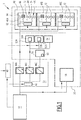
- the railway vehicle 1 comprises an onboard energy storage 10, consumer equipment 20 receiving electrical energy energy storage 10 especially when the railway vehicle passes through a geographical area (not shown) without an electrical network.
- power supply a static converter 30 for powering some of the consumer equipment, and a power management system 40 according to the invention.
- the static converter 30 comprises a control unit 42, and for example three conversion modules 44A, 44B and 44C.
- the module 44A is for example adapted to produce a three-phase electricity, a voltage of 400 V, and variable frequency.
- the frequencies produced are for example 45, 50, 55 or 60 Hz.
- the module 44B is for example adapted to produce a three-phase electricity, at 400 V, and 50 Hz.
- the module 44C is for example adapted to produce a direct current under a voltage of 24 V.
- the consumer equipment 20 is eligible for load shedding in order to reduce and / or optimize the quantity of electrical energy taken from the energy storage 10.
- the consumer equipment 20 comprises, for example, three HVAC equipment 46A, 46B, 46C located, at least partially, in a space 48 reserved for the passengers of the railway vehicle 1, two HVAC equipment 50A, 50B respectively located in a control cabin 52A. and in an off-duty booth 52B, a device 54 electrically connected to the conversion module 44B, a device 56 electrically connected to the module 44C, and advantageously a traction and braking system 58 of the railway vehicle 1.
- the traction and braking system 58 is energy consuming when it acts in tension, and advantageously generates energy when it acts in braking.
- the system 58 is electrically connected directly to the energy storage 10.
- the system 58 is adapted to operate if necessary according to at least one step reducing its energy consumption compared to a nominal step.
- the equipment 56 advantageously comprises an auxiliary battery 60 to provide for the supply of direct current by the module 44C.
- the equipment 56 is for example adapted to control the internal lighting of the railway vehicle 1.
- HVAC equipment 50A, 50B are electrically connected to module 44B.
- the space 48 reserved for passengers includes only one or two HVAC equipment, or more than three HVAC equipment.
- HVAC equipment 46A, 46B, 46C being similar to each other, only the equipment 46A will be described below.
- the equipment 46A includes a control unit 62, a ventilation unit 64 adapted to ventilate air in the space 48, a heating unit 66, and two space cooling units 68, 70.
- the equipment 46A comprises two heating units similar to the unit 66.
- Each of the groups 68, 70 includes a compressor 72 and a fan 74.
- the equipment 46A is able to receive a supply signal with variable frequency and voltage.
- the energy management system 40 will now be described with reference to the figure 2 . It represents an example of a power management system according to the invention.
- the energy management system 40 is intended to manage the supply of electrical energy to the consumer equipment 20.
- the energy management system 40 comprises an energy module 74 adapted to provide an energy parameter representative of a energy level available in the energy storage 10, and a location module 76 adapted to provide a location parameter representative of a location of the railway vehicle 1.
- the energy management system 40 is particularly intended to manage the supply of electrical energy to the static converter 30 and the system 58 of traction and braking.
- the energy management system 40 also comprises a calculation module 78 adapted to determine a desired operating state for each of the consumer equipment 20, for the static converter 30 and for the traction and braking system 58, and a module for determining the desired operating state. sending 80 to send each of these equipment an operating instruction according to the desired operating state.
- the energy management system 40 also comprises a memory 82, adapted in particular to keep information relating to the past operation of the consumer equipment 20, the static converter 30 and / or the 58 traction and braking system.
- the management system 40 is advantageously on board the railway vehicle 1, or, according to a variant not shown, is located at a distance and is adapted to communicate with the consumer equipment 20, the converter 30 and / or the traction system 58 and braking of the railway vehicle.
- the energy management system 40 is adapted to implement the steps of a method according to the invention, described below.
- the method comprises a step of obtaining the energy parameter by the energy module 74, and the location parameter by the location module 76, then a step of determining a desired operating state for each of the consumer equipment And advantageously for the static converter 30 or the conversion modules 44A, 44B and 44C and the traction and braking system 58 on the basis of the energy parameter and the location parameter.
- the method also comprises sending to each consumer equipment 20 and advantageously to the static converter 30 and the traction and braking system 58, by the sending module 80, an operating instruction requesting or imposing on the corresponding equipment the operate according to the desired operating condition that has been determined.
- the energy parameter is for example a representative percentage of the charge level of the energy storage 10. "100%" means that the storage 10 is fully charged, while “0%” means that the storage 10 is empty.
- the location parameter is for example an abscissa indicating the position of the railway vehicle 1 on a railway (not shown).
- the location module 76 is adapted to provide several location parameters, such as, for example, geographical coordinates.
- the management of the supply of electrical energy is carried out without taking into account the location of the railway vehicle 1, and the energy management system 40 is devoid of the location module 76.
- the determination of the desired operating state for each of the consumer equipment 20 uses at least one parameter representative of an operating state of the railway vehicle 1, for example taken from all or some of the following states: "Nominal”, “degraded”, “rescuing another railway vehicle”, “stationary”, “rolling”, and "with one or more stops planned during the crossing of the geographical zone devoid of an electrical network”.
- the operating instruction is individualized for each consumer equipment 20 and / or for each conversion module 44A, 44B and 44C and the system 58 for traction and braking.
- the set point may be a running operation degraded or reduced, or even a pure and simple interruption of the power supply of the consumer equipment 20 and / or the conversion module 44A, 44B and 44C and / or the system 58 traction and concerned.
- the determination of the desired operating state for the traction and braking system 58 comprises, for example, a calculation of a reduced power or supply current to be consumed by this consumer equipment.
- the determination of the desired operating state for the traction and braking system 58 comprises, for example, a calculation of a maximum speed setpoint intended not to be exceeded by the railway vehicle 1.
- the operating set point comprises, for example, a reduction in the frequency and / or the voltage produced.
- the determination of the desired operating state is carried out by the calculation module 78, for example according to criteria summarized in Table 1 below.
- Table 1 ⁇ / u> Consumer equipment 20 Operation on electricity network Energy parameter ⁇ level 1 Energy parameter ⁇ level 2 Energy parameter ⁇ level 3 Energy parameter ⁇ level 4 Energy parameter ⁇ level 5 Energy parameter ⁇ level 6
- HVAC equipment 46A to 46C 400 V variable frequency 45 to 60 Hz six compressors 72 allowed 45 Hz six compressors 72 allowed 45 Hz five compressors 72 allowed 45 Hz four compressors 72 allowed 45 Hz three compressors 72 allowed Interruption of the electricity supply Interruption of the electricity supply HVAC50A, 50B cabin equipment Full power Full power Full power Only in the cabin in use Only in the cabin in use Interruption of the electricity supply Interruption of the electricity supply Equipment 54 400 V 50 Hz Full power Full power Full power Full power Interruption of supply Equipment 56 24 V DC current Full power Full power Power Supply by auxiliary battery 60 Power supply by auxiliary battery 60 Power supply by auxiliary battery 60 Power supply by auxiliary battery
- lines 2 to 5 (from the top of the table) provide the desired operating status respectively for HVAC 46A, 46B, 46C passenger-only equipment, for HVAC 50A, 50B cockpit equipment 52A, 52B, for the equipment 54 supplied with fixed-frequency or fixed-phase single-phase three-phase current, and for the direct-current equipment 56.
- the frequency and / or supply voltage of HVAC equipment 46A, 46B, 46C reserved for passengers are determined using the energy parameter.
- each type of consumer equipment 20 is defined one or more thresholds own (s) to this equipment.
- such consumer equipment 20 may have a level 2 which differs from level 2 of such other consumer equipment.
- the energy levels are adapted according to the location of the railway vehicle 1.
- the energy management system 40 may decide not to immediately apply the operating mode corresponding to the parameter of energy obtained.
- the operating mode corresponding to the energy parameter obtained is for example applied if the energy parameter decreases, or if the railway vehicle 1 is late in leaving said zone, or if the railway vehicle leaves the predicted non-powered area.
- the number of compressors 72 that is desired in service is six (ie all compressors 72) if the energy parameter is greater than or equal to at level 1. This number is five if the energy parameter is strictly lower than level 1 and greater than or equal to level 2. This number is gradually reduced to three when the energy parameter is strictly lower than level 3 and greater than or equal to level 4. When the energy parameter is strictly less than level 4, the number of compressors 72 to be in use falls to zero, that is, the desired operation results in a shutdown. of all compressors 72.
- the unloading logic consists in supplying these two HVAC equipment as long as the energy parameter is greater than or equal to level 2, then to n ' to supply that located in the control cabin 52A in service if the energy parameter is strictly less than level 2 and greater than or equal to level 4. Finally, if the energy parameter is strictly lower than level 4, none of the HVAC equipment 50A, 50B should only be supplied with electricity.
- a similar logic is applied for the desired operating state of the heating elements 66, and their possible shedding.
- the power supply must, for example, be interrupted if the energy parameter is strictly less than level 5.
- the power supply must, for example, be interrupted if the energy parameter is strictly less than level 2.
- the auxiliary battery 60 then takes the relay to power the equipment 54.
- the determination of the desired operation is achievable independently for each type of consumer equipment. For example, it is possible to inhibit the shedding of such or such type of consumer equipment 20.
- the computing unit 78 advantageously determines which HVAC equipment should be concerned by the load shedding of at least one of their compressors 72 to reach the number of compressors in desired operation. This will be described below with reference to the figure 3 .
- a test 80 is first performed to determine whether the number of compressors 72 actually operating in the HVAC equipment 46A, 46B, 46C is strictly greater than the number of compressors 72 to be in operation as determined as explained above.
- test 80 If the answer to the test 80 is "no", the test is for example iterated (or renewed after a predetermined period of time).
- a step 82 is performed to establish the list of HVAC equipment having their two compressors 72 in operation.
- a test 84 is performed to determine if the number of HVAC equipment in this list is equal to 1.
- the relevant HVAC equipment is selected in a step 86, and the operating setpoint sent by the sending module 80 includes stopping one of the compressors 72 of the selected HVAC equipment.
- a step 88 is performed to calculate a residual cycle time of each compressor 72 in operation in the HVAC equipment of the list obtained in step 82.
- the residual cycle time of each compressor 72 is representative of the difference between a minimum running time without interruption of the compressor (given by the manufacturer), for example 3 minutes, and an actual operating time without stopping the compressor.
- Step 88 provides, for each HVAC equipment in the list obtained in step 82, the sum of the cycle residuals.
- Step 88 finally determines which HVAC equipment in the list has a sum of the minimum residual times.
- a test 90 is then performed to determine if the number of HVAC equipment having a sum of the minimum cycle residuals is equal to 1.
- the relevant HVAC equipment is selected in a step 92, and the operating setpoint sent by the sending module 80 includes stopping one of the compressors 72 of the selected HVAC equipment.
- step 88 for each HVAC equipment in the list obtained in step 82, the minimum of the compressor cycle residuals is used instead of the sum of the cycle residuals.
- a step 94 is performed to calculate the number of starts, in an elapsed period, of each compressor 72 in operation among HVAC equipment from the list obtained at the step 82.
- the past period considered is for example one hour.
- Step 94 provides, for each HVAC equipment in the list obtained in step 82, the sum of the numbers of starts.
- Step 94 finally determines which HVAC equipment in the list has a sum of the minimum number of starts.
- a test 96 is then performed to determine if the number of HVAC equipment having a sum of the minimum number of starts is equal to 1.
- the relevant HVAC equipment is selected in a step 98, and the operating setpoint sent by the sending module 80 includes stopping one of the compressors 72 of the selected HVAC equipment.
- step 94 for each HVAC equipment item from the list obtained in step 82, the minimum of the start numbers is used instead of the sum of the number of starts.
- a step 100 is advantageously performed to select the equipment to be discharged among the HVAC equipment 46A, 46B, 46C based on other considerations. For example, we choose to offload the HVAC equipment whose last load shedding is the oldest.
- a test 102 is first performed to determine whether the HVAC equipment considered is to be shed.
- test 102 If the answer to the test 102 is "no", the test 102 is for example iterated (or renewed after a predetermined period of time). If the answer is "yes”, a step 104 is performed to calculate the residual cycle time (as defined above) of each compressor 72 of the HVAC equipment considered. Step 104 then determines which compressors 72 have a minimum cycle time remaining.
- a test 106 is then performed to determine if the number of compressors 72 having a minimum residual cycle time is equal to 1.
- the compressor 72 concerned is selected in a step 108, and the operating instruction sent by the sending module 80 includes stopping the compressor 72 of the HVAC equipment concerned.
- a step 110 is performed to calculate the number of starts, in an elapsed period, of each compressor 72 of the HVAC equipment concerned.
- the past period considered is for example one hour.
- Step 110 determines which compressors 72 have a minimum number of starts.
- a test 112 is performed to determine whether the number of compressors 72 having a minimum number of starts is equal to 1.
- the compressor 72 concerned is selected in a step 114, and the operating instruction sent by the sending module 80 includes stopping the compressor 72 of the HVAC equipment considered.
- a step 116 is advantageously performed to select one of the compressors 72 on the basis of a given criterion, for example, by the supplier of the compressors 72.
- the management of the supply of energy to the consumer equipment 20 is carried out in an extremely progressive manner, by minimizing the number of equipment shed.
- the risk of inconveniencing the passengers or the personnel of the railway vehicle 1 is minimized.
- the conversion modules 44A, 44B and 44C are considered as energy consuming equipment and treated as the consumer equipment 20.
- the invention also has the advantage of allowing individualized management by type of equipment.
- the invention is of interest in all situations where it is desired to reduce the energy consumption of the railway vehicle 1, therefore not only when crossing a geographical area devoid of an electrical network. food.
- the invention makes it possible to request one or more railway vehicles similar to the railway vehicle 1 to consume less electrical energy.
- it is possible to avoid unloading portions of the network.
Landscapes
- Engineering & Computer Science (AREA)
- Power Engineering (AREA)
- Transportation (AREA)
- Mechanical Engineering (AREA)
- Life Sciences & Earth Sciences (AREA)
- Sustainable Development (AREA)
- Sustainable Energy (AREA)
- Electric Propulsion And Braking For Vehicles (AREA)
Priority Applications (1)
| Application Number | Priority Date | Filing Date | Title |
|---|---|---|---|
| PL18156480T PL3360723T3 (pl) | 2017-02-14 | 2018-02-13 | Sposób zarządzania energią elektryczną w pojeździe kolejowym, odpowiedni system zarządzania energią oraz odpowiedni pojazd kolejowy |
Applications Claiming Priority (1)
| Application Number | Priority Date | Filing Date | Title |
|---|---|---|---|
| FR1751191A FR3062823B1 (fr) | 2017-02-14 | 2017-02-14 | Procede de gestion d'energie electrique dans un vehicule ferroviaire, systeme de gestion d'energie correspondant et vehicule ferroviaire correspondant |
Publications (2)
| Publication Number | Publication Date |
|---|---|
| EP3360723A1 true EP3360723A1 (de) | 2018-08-15 |
| EP3360723B1 EP3360723B1 (de) | 2020-04-01 |
Family
ID=58547718
Family Applications (1)
| Application Number | Title | Priority Date | Filing Date |
|---|---|---|---|
| EP18156480.8A Active EP3360723B1 (de) | 2017-02-14 | 2018-02-13 | Verfahren zur steuerung der elektrischen energie in einem schienenfahrzeug, entsprechendes energiesteuerungssystem und entsprechendes schienenfahrzeug |
Country Status (5)
| Country | Link |
|---|---|
| EP (1) | EP3360723B1 (de) |
| AU (1) | AU2018200854B2 (de) |
| ES (1) | ES2800204T3 (de) |
| FR (1) | FR3062823B1 (de) |
| PL (1) | PL3360723T3 (de) |
Citations (4)
| Publication number | Priority date | Publication date | Assignee | Title |
|---|---|---|---|---|
| EP1129892A1 (de) * | 2000-03-01 | 2001-09-05 | Renault V.I. | Energieregelungsvorrichtung für Fahrzeuge |
| EP1864846A1 (de) * | 2006-06-09 | 2007-12-12 | Alstom Transport S.A. | Stromversorgungssystem und -verfahren für ein Schienenfahrzeug, Wandler, Steuereinheit, Klimaanlage für dieses System |
| EP2340957A1 (de) * | 2008-10-23 | 2011-07-06 | Mitsubishi Electric Corporation | Antriebssteuervorrichtung für elektroauto |
| EP2994332A1 (de) * | 2013-05-08 | 2016-03-16 | Volvo Truck Corporation | Energieverwaltungssystem für nicht-schienengebundenes fahrzeug |
Family Cites Families (3)
| Publication number | Priority date | Publication date | Assignee | Title |
|---|---|---|---|---|
| DE10243857A1 (de) * | 2002-09-20 | 2004-04-01 | Siemens Ag | Verfahren zur Versorgung von in einem Eisenbahnzug vorhandenen Zusatzgeräten mit elektrischer Energie |
| DE102013207952A1 (de) * | 2013-04-30 | 2014-10-30 | Siemens Aktiengesellschaft | Vorrichtung zum Betreiben zumindest eines elektrischen Verbrauchers eines Schienenfahrzeugs |
| US20160176414A1 (en) * | 2016-03-02 | 2016-06-23 | Electro-Motive Diesel, Inc. | Power management system for train |
-
2017
- 2017-02-14 FR FR1751191A patent/FR3062823B1/fr not_active Expired - Fee Related
-
2018
- 2018-02-06 AU AU2018200854A patent/AU2018200854B2/en active Active
- 2018-02-13 ES ES18156480T patent/ES2800204T3/es active Active
- 2018-02-13 PL PL18156480T patent/PL3360723T3/pl unknown
- 2018-02-13 EP EP18156480.8A patent/EP3360723B1/de active Active
Patent Citations (4)
| Publication number | Priority date | Publication date | Assignee | Title |
|---|---|---|---|---|
| EP1129892A1 (de) * | 2000-03-01 | 2001-09-05 | Renault V.I. | Energieregelungsvorrichtung für Fahrzeuge |
| EP1864846A1 (de) * | 2006-06-09 | 2007-12-12 | Alstom Transport S.A. | Stromversorgungssystem und -verfahren für ein Schienenfahrzeug, Wandler, Steuereinheit, Klimaanlage für dieses System |
| EP2340957A1 (de) * | 2008-10-23 | 2011-07-06 | Mitsubishi Electric Corporation | Antriebssteuervorrichtung für elektroauto |
| EP2994332A1 (de) * | 2013-05-08 | 2016-03-16 | Volvo Truck Corporation | Energieverwaltungssystem für nicht-schienengebundenes fahrzeug |
Also Published As
| Publication number | Publication date |
|---|---|
| EP3360723B1 (de) | 2020-04-01 |
| ES2800204T3 (es) | 2020-12-28 |
| PL3360723T3 (pl) | 2020-11-30 |
| AU2018200854A1 (en) | 2018-08-30 |
| FR3062823B1 (fr) | 2021-04-23 |
| AU2018200854B2 (en) | 2023-12-07 |
| FR3062823A1 (fr) | 2018-08-17 |
Similar Documents
| Publication | Publication Date | Title |
|---|---|---|
| EP1864846B1 (de) | Stromversorgungssystem und -verfahren für ein Schienenfahrzeug, Wandler, Steuereinheit, Klimaanlage für dieses System | |
| JP4316501B2 (ja) | 少なくとも1つの電気モータと、燃料電池システム及び動的エネルギーシステムを含むハイブリッドエネルギーシステムとを備える車両のエネルギー供給を制御する方法及び装置 | |
| CA2426372C (fr) | Procede et dispositif pour le controle et la regulation de la puissance consommee par un systeme de transport | |
| US7014001B2 (en) | High-voltage energy regulated conversion circuit | |
| CN112141032B (zh) | 气候受控车辆、运输气候控制设备、车辆改装和运行方法 | |
| US20080215199A1 (en) | Vehicle-use dual voltage type power supply apparatus | |
| EP2626263B1 (de) | Luftbedarfsangepasste Kompressorsteuerung | |
| WO2009153416A1 (fr) | Système de régulation énergétique adapté à l'alimentation d'une ligne électrique de distribution d'énergie à des véhicules | |
| US8441143B2 (en) | Method and system for rail vehicle power distribution and management | |
| US20190052085A1 (en) | Power management system | |
| FR3100794A1 (fr) | Procédés et dispositifs pour piloter un système de refroidissement | |
| US7443048B2 (en) | Method for operating an electrical system | |
| US9493128B2 (en) | Method for operating an on-board power supply system of a motor vehicle | |
| FR2965128B1 (fr) | Procede et dispositif de gestion d'un generateur d'un systeme de recuperation d'energie d'un vehicule automobile | |
| EP3360723B1 (de) | Verfahren zur steuerung der elektrischen energie in einem schienenfahrzeug, entsprechendes energiesteuerungssystem und entsprechendes schienenfahrzeug | |
| FR2976138A1 (fr) | Systeme de stockage d'energie capacitif | |
| FR3071460A1 (fr) | Gestion securisee de la puissance electrique disponible dans un vehicule pour un systeme de freinage electrique | |
| WO2019025775A1 (en) | SYSTEM AND METHOD FOR CONTROLLING DEVICES IN AN ENERGY DISTRIBUTION NETWORK | |
| EP2807717B1 (de) | Verfahren zur verwaltung der elektrischen energie einer elektrischen architektur eines kraftfahrzeugs und kraftfahrzeug mit einem solchen verfahren | |
| FR2974041A1 (fr) | Systeme d'alimentation embarque dans un vehicule, procede d'alimentation electrique et vehicule associes | |
| US20240140243A1 (en) | Method for providing ancillary services | |
| FR3092212A1 (fr) | Procede et systeme de gestion de l’alimentation d’un reseau de bord d’un vehicule automobile | |
| CN116985826A (zh) | 车辆的控制方法、装置、计算机可读存储介质和处理器 | |
| CN120096326A (zh) | 一种车辆的控制方法、装置、车辆及介质 | |
| EP4721264A1 (de) | Verfahren zur steuerung eines kraftfahrzeugwechselstromgenerators |
Legal Events
| Date | Code | Title | Description |
|---|---|---|---|
| PUAI | Public reference made under article 153(3) epc to a published international application that has entered the european phase |
Free format text: ORIGINAL CODE: 0009012 |
|
| STAA | Information on the status of an ep patent application or granted ep patent |
Free format text: STATUS: THE APPLICATION HAS BEEN PUBLISHED |
|
| STAA | Information on the status of an ep patent application or granted ep patent |
Free format text: STATUS: REQUEST FOR EXAMINATION WAS MADE |
|
| AK | Designated contracting states |
Kind code of ref document: A1 Designated state(s): AL AT BE BG CH CY CZ DE DK EE ES FI FR GB GR HR HU IE IS IT LI LT LU LV MC MK MT NL NO PL PT RO RS SE SI SK SM TR |
|
| AX | Request for extension of the european patent |
Extension state: BA ME |
|
| 17P | Request for examination filed |
Effective date: 20180806 |
|
| RBV | Designated contracting states (corrected) |
Designated state(s): AL AT BE BG CH CY CZ DE DK EE ES FI FR GB GR HR HU IE IS IT LI LT LU LV MC MK MT NL NO PL PT RO RS SE SI SK SM TR |
|
| STAA | Information on the status of an ep patent application or granted ep patent |
Free format text: STATUS: EXAMINATION IS IN PROGRESS |
|
| 17Q | First examination report despatched |
Effective date: 20190426 |
|
| REG | Reference to a national code |
Ref country code: DE Ref legal event code: R079 Ref document number: 602018003338 Country of ref document: DE Free format text: PREVIOUS MAIN CLASS: B60L0011180000 Ipc: B60L0003000000 |
|
| GRAP | Despatch of communication of intention to grant a patent |
Free format text: ORIGINAL CODE: EPIDOSNIGR1 |
|
| STAA | Information on the status of an ep patent application or granted ep patent |
Free format text: STATUS: GRANT OF PATENT IS INTENDED |
|
| RIC1 | Information provided on ipc code assigned before grant |
Ipc: B60L 1/02 20060101ALI20190916BHEP Ipc: B60L 1/08 20060101ALI20190916BHEP Ipc: B60L 3/00 20190101AFI20190916BHEP Ipc: B60L 1/00 20060101ALI20190916BHEP Ipc: B60L 15/20 20060101ALI20190916BHEP |
|
| INTG | Intention to grant announced |
Effective date: 20191004 |
|
| GRAS | Grant fee paid |
Free format text: ORIGINAL CODE: EPIDOSNIGR3 |
|
| GRAA | (expected) grant |
Free format text: ORIGINAL CODE: 0009210 |
|
| STAA | Information on the status of an ep patent application or granted ep patent |
Free format text: STATUS: THE PATENT HAS BEEN GRANTED |
|
| AK | Designated contracting states |
Kind code of ref document: B1 Designated state(s): AL AT BE BG CH CY CZ DE DK EE ES FI FR GB GR HR HU IE IS IT LI LT LU LV MC MK MT NL NO PL PT RO RS SE SI SK SM TR |
|
| REG | Reference to a national code |
Ref country code: GB Ref legal event code: FG4D Free format text: NOT ENGLISH |
|
| REG | Reference to a national code |
Ref country code: AT Ref legal event code: REF Ref document number: 1250931 Country of ref document: AT Kind code of ref document: T Effective date: 20200415 Ref country code: CH Ref legal event code: EP |
|
| REG | Reference to a national code |
Ref country code: DE Ref legal event code: R096 Ref document number: 602018003338 Country of ref document: DE |
|
| REG | Reference to a national code |
Ref country code: IE Ref legal event code: FG4D Free format text: LANGUAGE OF EP DOCUMENT: FRENCH |
|
| REG | Reference to a national code |
Ref country code: CH Ref legal event code: NV Representative=s name: DENNEMEYER AG, CH |
|
| PG25 | Lapsed in a contracting state [announced via postgrant information from national office to epo] |
Ref country code: BG Free format text: LAPSE BECAUSE OF FAILURE TO SUBMIT A TRANSLATION OF THE DESCRIPTION OR TO PAY THE FEE WITHIN THE PRESCRIBED TIME-LIMIT Effective date: 20200701 |
|
| REG | Reference to a national code |
Ref country code: NL Ref legal event code: MP Effective date: 20200401 |
|
| REG | Reference to a national code |
Ref country code: LT Ref legal event code: MG4D |
|
| PG25 | Lapsed in a contracting state [announced via postgrant information from national office to epo] |
Ref country code: FI Free format text: LAPSE BECAUSE OF FAILURE TO SUBMIT A TRANSLATION OF THE DESCRIPTION OR TO PAY THE FEE WITHIN THE PRESCRIBED TIME-LIMIT Effective date: 20200401 Ref country code: IS Free format text: LAPSE BECAUSE OF FAILURE TO SUBMIT A TRANSLATION OF THE DESCRIPTION OR TO PAY THE FEE WITHIN THE PRESCRIBED TIME-LIMIT Effective date: 20200801 Ref country code: SE Free format text: LAPSE BECAUSE OF FAILURE TO SUBMIT A TRANSLATION OF THE DESCRIPTION OR TO PAY THE FEE WITHIN THE PRESCRIBED TIME-LIMIT Effective date: 20200401 Ref country code: GR Free format text: LAPSE BECAUSE OF FAILURE TO SUBMIT A TRANSLATION OF THE DESCRIPTION OR TO PAY THE FEE WITHIN THE PRESCRIBED TIME-LIMIT Effective date: 20200702 Ref country code: NO Free format text: LAPSE BECAUSE OF FAILURE TO SUBMIT A TRANSLATION OF THE DESCRIPTION OR TO PAY THE FEE WITHIN THE PRESCRIBED TIME-LIMIT Effective date: 20200701 Ref country code: PT Free format text: LAPSE BECAUSE OF FAILURE TO SUBMIT A TRANSLATION OF THE DESCRIPTION OR TO PAY THE FEE WITHIN THE PRESCRIBED TIME-LIMIT Effective date: 20200817 Ref country code: LT Free format text: LAPSE BECAUSE OF FAILURE TO SUBMIT A TRANSLATION OF THE DESCRIPTION OR TO PAY THE FEE WITHIN THE PRESCRIBED TIME-LIMIT Effective date: 20200401 Ref country code: CZ Free format text: LAPSE BECAUSE OF FAILURE TO SUBMIT A TRANSLATION OF THE DESCRIPTION OR TO PAY THE FEE WITHIN THE PRESCRIBED TIME-LIMIT Effective date: 20200401 Ref country code: NL Free format text: LAPSE BECAUSE OF FAILURE TO SUBMIT A TRANSLATION OF THE DESCRIPTION OR TO PAY THE FEE WITHIN THE PRESCRIBED TIME-LIMIT Effective date: 20200401 |
|
| REG | Reference to a national code |
Ref country code: AT Ref legal event code: MK05 Ref document number: 1250931 Country of ref document: AT Kind code of ref document: T Effective date: 20200401 |
|
| PG25 | Lapsed in a contracting state [announced via postgrant information from national office to epo] |
Ref country code: RS Free format text: LAPSE BECAUSE OF FAILURE TO SUBMIT A TRANSLATION OF THE DESCRIPTION OR TO PAY THE FEE WITHIN THE PRESCRIBED TIME-LIMIT Effective date: 20200401 Ref country code: LV Free format text: LAPSE BECAUSE OF FAILURE TO SUBMIT A TRANSLATION OF THE DESCRIPTION OR TO PAY THE FEE WITHIN THE PRESCRIBED TIME-LIMIT Effective date: 20200401 Ref country code: HR Free format text: LAPSE BECAUSE OF FAILURE TO SUBMIT A TRANSLATION OF THE DESCRIPTION OR TO PAY THE FEE WITHIN THE PRESCRIBED TIME-LIMIT Effective date: 20200401 |
|
| PG25 | Lapsed in a contracting state [announced via postgrant information from national office to epo] |
Ref country code: AL Free format text: LAPSE BECAUSE OF FAILURE TO SUBMIT A TRANSLATION OF THE DESCRIPTION OR TO PAY THE FEE WITHIN THE PRESCRIBED TIME-LIMIT Effective date: 20200401 |
|
| REG | Reference to a national code |
Ref country code: DE Ref legal event code: R097 Ref document number: 602018003338 Country of ref document: DE |
|
| PG25 | Lapsed in a contracting state [announced via postgrant information from national office to epo] |
Ref country code: DK Free format text: LAPSE BECAUSE OF FAILURE TO SUBMIT A TRANSLATION OF THE DESCRIPTION OR TO PAY THE FEE WITHIN THE PRESCRIBED TIME-LIMIT Effective date: 20200401 Ref country code: AT Free format text: LAPSE BECAUSE OF FAILURE TO SUBMIT A TRANSLATION OF THE DESCRIPTION OR TO PAY THE FEE WITHIN THE PRESCRIBED TIME-LIMIT Effective date: 20200401 Ref country code: RO Free format text: LAPSE BECAUSE OF FAILURE TO SUBMIT A TRANSLATION OF THE DESCRIPTION OR TO PAY THE FEE WITHIN THE PRESCRIBED TIME-LIMIT Effective date: 20200401 Ref country code: EE Free format text: LAPSE BECAUSE OF FAILURE TO SUBMIT A TRANSLATION OF THE DESCRIPTION OR TO PAY THE FEE WITHIN THE PRESCRIBED TIME-LIMIT Effective date: 20200401 Ref country code: SM Free format text: LAPSE BECAUSE OF FAILURE TO SUBMIT A TRANSLATION OF THE DESCRIPTION OR TO PAY THE FEE WITHIN THE PRESCRIBED TIME-LIMIT Effective date: 20200401 |
|
| PLBE | No opposition filed within time limit |
Free format text: ORIGINAL CODE: 0009261 |
|
| STAA | Information on the status of an ep patent application or granted ep patent |
Free format text: STATUS: NO OPPOSITION FILED WITHIN TIME LIMIT |
|
| PG25 | Lapsed in a contracting state [announced via postgrant information from national office to epo] |
Ref country code: SK Free format text: LAPSE BECAUSE OF FAILURE TO SUBMIT A TRANSLATION OF THE DESCRIPTION OR TO PAY THE FEE WITHIN THE PRESCRIBED TIME-LIMIT Effective date: 20200401 |
|
| 26N | No opposition filed |
Effective date: 20210112 |
|
| PG25 | Lapsed in a contracting state [announced via postgrant information from national office to epo] |
Ref country code: SI Free format text: LAPSE BECAUSE OF FAILURE TO SUBMIT A TRANSLATION OF THE DESCRIPTION OR TO PAY THE FEE WITHIN THE PRESCRIBED TIME-LIMIT Effective date: 20200401 |
|
| PG25 | Lapsed in a contracting state [announced via postgrant information from national office to epo] |
Ref country code: MC Free format text: LAPSE BECAUSE OF FAILURE TO SUBMIT A TRANSLATION OF THE DESCRIPTION OR TO PAY THE FEE WITHIN THE PRESCRIBED TIME-LIMIT Effective date: 20200401 |
|
| PG25 | Lapsed in a contracting state [announced via postgrant information from national office to epo] |
Ref country code: LU Free format text: LAPSE BECAUSE OF NON-PAYMENT OF DUE FEES Effective date: 20210213 |
|
| PG25 | Lapsed in a contracting state [announced via postgrant information from national office to epo] |
Ref country code: IE Free format text: LAPSE BECAUSE OF NON-PAYMENT OF DUE FEES Effective date: 20210213 |
|
| GBPC | Gb: european patent ceased through non-payment of renewal fee |
Effective date: 20220213 |
|
| PG25 | Lapsed in a contracting state [announced via postgrant information from national office to epo] |
Ref country code: GB Free format text: LAPSE BECAUSE OF NON-PAYMENT OF DUE FEES Effective date: 20220213 |
|
| PG25 | Lapsed in a contracting state [announced via postgrant information from national office to epo] |
Ref country code: CY Free format text: LAPSE BECAUSE OF FAILURE TO SUBMIT A TRANSLATION OF THE DESCRIPTION OR TO PAY THE FEE WITHIN THE PRESCRIBED TIME-LIMIT Effective date: 20200401 |
|
| PG25 | Lapsed in a contracting state [announced via postgrant information from national office to epo] |
Ref country code: HU Free format text: LAPSE BECAUSE OF FAILURE TO SUBMIT A TRANSLATION OF THE DESCRIPTION OR TO PAY THE FEE WITHIN THE PRESCRIBED TIME-LIMIT; INVALID AB INITIO Effective date: 20180213 |
|
| P01 | Opt-out of the competence of the unified patent court (upc) registered |
Effective date: 20230823 |
|
| PG25 | Lapsed in a contracting state [announced via postgrant information from national office to epo] |
Ref country code: MK Free format text: LAPSE BECAUSE OF FAILURE TO SUBMIT A TRANSLATION OF THE DESCRIPTION OR TO PAY THE FEE WITHIN THE PRESCRIBED TIME-LIMIT Effective date: 20200401 |
|
| PG25 | Lapsed in a contracting state [announced via postgrant information from national office to epo] |
Ref country code: TR Free format text: LAPSE BECAUSE OF FAILURE TO SUBMIT A TRANSLATION OF THE DESCRIPTION OR TO PAY THE FEE WITHIN THE PRESCRIBED TIME-LIMIT Effective date: 20200401 |
|
| PG25 | Lapsed in a contracting state [announced via postgrant information from national office to epo] |
Ref country code: MT Free format text: LAPSE BECAUSE OF FAILURE TO SUBMIT A TRANSLATION OF THE DESCRIPTION OR TO PAY THE FEE WITHIN THE PRESCRIBED TIME-LIMIT Effective date: 20200401 |
|
| REG | Reference to a national code |
Ref country code: ES Ref legal event code: PC2A Owner name: ALSTOM HOLDINGS Effective date: 20250310 |
|
| REG | Reference to a national code |
Ref country code: BE Ref legal event code: PD Owner name: ALSTOM HOLDINGS; FR Free format text: DETAILS ASSIGNMENT: CHANGE OF OWNER(S), ASSIGNMENT; FORMER OWNER NAME: ALSTOM TRANSPORT TECHNOLOGIES Effective date: 20241025 |
|
| PGFP | Annual fee paid to national office [announced via postgrant information from national office to epo] |
Ref country code: ES Payment date: 20250331 Year of fee payment: 8 |
|
| REG | Reference to a national code |
Ref country code: CH Ref legal event code: U11 Free format text: ST27 STATUS EVENT CODE: U-0-0-U10-U11 (AS PROVIDED BY THE NATIONAL OFFICE) Effective date: 20260301 |
|
| PGFP | Annual fee paid to national office [announced via postgrant information from national office to epo] |
Ref country code: DE Payment date: 20260218 Year of fee payment: 9 |
|
| PGFP | Annual fee paid to national office [announced via postgrant information from national office to epo] |
Ref country code: BE Payment date: 20260218 Year of fee payment: 9 Ref country code: IT Payment date: 20260224 Year of fee payment: 9 |
|
| PGFP | Annual fee paid to national office [announced via postgrant information from national office to epo] |
Ref country code: FR Payment date: 20260218 Year of fee payment: 9 |
|
| PGFP | Annual fee paid to national office [announced via postgrant information from national office to epo] |
Ref country code: CH Payment date: 20260301 Year of fee payment: 9 |
|
| PGFP | Annual fee paid to national office [announced via postgrant information from national office to epo] |
Ref country code: PL Payment date: 20260209 Year of fee payment: 9 |