EP3360741B1 - Procédé de fonctionnement d'un véhicule, en particulier un véhicule utilitaire - Google Patents
Procédé de fonctionnement d'un véhicule, en particulier un véhicule utilitaire Download PDFInfo
- Publication number
- EP3360741B1 EP3360741B1 EP18152016.4A EP18152016A EP3360741B1 EP 3360741 B1 EP3360741 B1 EP 3360741B1 EP 18152016 A EP18152016 A EP 18152016A EP 3360741 B1 EP3360741 B1 EP 3360741B1
- Authority
- EP
- European Patent Office
- Prior art keywords
- vehicle
- driving
- driving strategy
- transmitted
- bend
- Prior art date
- Legal status (The legal status is an assumption and is not a legal conclusion. Google has not performed a legal analysis and makes no representation as to the accuracy of the status listed.)
- Active
Links
Images
Classifications
-
- G—PHYSICS
- G01—MEASURING; TESTING
- G01C—MEASURING DISTANCES, LEVELS OR BEARINGS; SURVEYING; NAVIGATION; GYROSCOPIC INSTRUMENTS; PHOTOGRAMMETRY OR VIDEOGRAMMETRY
- G01C21/00—Navigation; Navigational instruments not provided for in groups G01C1/00 - G01C19/00
- G01C21/26—Navigation; Navigational instruments not provided for in groups G01C1/00 - G01C19/00 specially adapted for navigation in a road network
- G01C21/34—Route searching; Route guidance
- G01C21/36—Input/output arrangements for on-board computers
- G01C21/3697—Output of additional, non-guidance related information, e.g. low fuel level
-
- B—PERFORMING OPERATIONS; TRANSPORTING
- B60—VEHICLES IN GENERAL
- B60K—ARRANGEMENT OR MOUNTING OF PROPULSION UNITS OR OF TRANSMISSIONS IN VEHICLES; ARRANGEMENT OR MOUNTING OF PLURAL DIVERSE PRIME-MOVERS IN VEHICLES; AUXILIARY DRIVES FOR VEHICLES; INSTRUMENTATION OR DASHBOARDS FOR VEHICLES; ARRANGEMENTS IN CONNECTION WITH COOLING, AIR INTAKE, GAS EXHAUST OR FUEL SUPPLY OF PROPULSION UNITS IN VEHICLES
- B60K31/00—Vehicle fittings, acting on a single sub-unit only, for automatically controlling vehicle speed, i.e. preventing speed from exceeding an arbitrarily established velocity or maintaining speed at a particular velocity, as selected by the vehicle operator
- B60K31/0066—Vehicle fittings, acting on a single sub-unit only, for automatically controlling vehicle speed, i.e. preventing speed from exceeding an arbitrarily established velocity or maintaining speed at a particular velocity, as selected by the vehicle operator responsive to vehicle path curvature
-
- B—PERFORMING OPERATIONS; TRANSPORTING
- B60—VEHICLES IN GENERAL
- B60W—CONJOINT CONTROL OF VEHICLE SUB-UNITS OF DIFFERENT TYPE OR DIFFERENT FUNCTION; CONTROL SYSTEMS SPECIALLY ADAPTED FOR HYBRID VEHICLES; ROAD VEHICLE DRIVE CONTROL SYSTEMS FOR PURPOSES NOT RELATED TO THE CONTROL OF A PARTICULAR SUB-UNIT
- B60W10/00—Conjoint control of vehicle sub-units of different type or different function
-
- B—PERFORMING OPERATIONS; TRANSPORTING
- B60—VEHICLES IN GENERAL
- B60W—CONJOINT CONTROL OF VEHICLE SUB-UNITS OF DIFFERENT TYPE OR DIFFERENT FUNCTION; CONTROL SYSTEMS SPECIALLY ADAPTED FOR HYBRID VEHICLES; ROAD VEHICLE DRIVE CONTROL SYSTEMS FOR PURPOSES NOT RELATED TO THE CONTROL OF A PARTICULAR SUB-UNIT
- B60W10/00—Conjoint control of vehicle sub-units of different type or different function
- B60W10/04—Conjoint control of vehicle sub-units of different type or different function including control of propulsion units
-
- B—PERFORMING OPERATIONS; TRANSPORTING
- B60—VEHICLES IN GENERAL
- B60W—CONJOINT CONTROL OF VEHICLE SUB-UNITS OF DIFFERENT TYPE OR DIFFERENT FUNCTION; CONTROL SYSTEMS SPECIALLY ADAPTED FOR HYBRID VEHICLES; ROAD VEHICLE DRIVE CONTROL SYSTEMS FOR PURPOSES NOT RELATED TO THE CONTROL OF A PARTICULAR SUB-UNIT
- B60W10/00—Conjoint control of vehicle sub-units of different type or different function
- B60W10/18—Conjoint control of vehicle sub-units of different type or different function including control of braking systems
-
- B—PERFORMING OPERATIONS; TRANSPORTING
- B60—VEHICLES IN GENERAL
- B60W—CONJOINT CONTROL OF VEHICLE SUB-UNITS OF DIFFERENT TYPE OR DIFFERENT FUNCTION; CONTROL SYSTEMS SPECIALLY ADAPTED FOR HYBRID VEHICLES; ROAD VEHICLE DRIVE CONTROL SYSTEMS FOR PURPOSES NOT RELATED TO THE CONTROL OF A PARTICULAR SUB-UNIT
- B60W20/00—Control systems specially adapted for hybrid vehicles
-
- B—PERFORMING OPERATIONS; TRANSPORTING
- B60—VEHICLES IN GENERAL
- B60W—CONJOINT CONTROL OF VEHICLE SUB-UNITS OF DIFFERENT TYPE OR DIFFERENT FUNCTION; CONTROL SYSTEMS SPECIALLY ADAPTED FOR HYBRID VEHICLES; ROAD VEHICLE DRIVE CONTROL SYSTEMS FOR PURPOSES NOT RELATED TO THE CONTROL OF A PARTICULAR SUB-UNIT
- B60W30/00—Purposes of road vehicle drive control systems not related to the control of a particular sub-unit, e.g. of systems using conjoint control of vehicle sub-units
- B60W30/02—Control of vehicle driving stability
- B60W30/045—Improving turning performance
-
- B—PERFORMING OPERATIONS; TRANSPORTING
- B60—VEHICLES IN GENERAL
- B60W—CONJOINT CONTROL OF VEHICLE SUB-UNITS OF DIFFERENT TYPE OR DIFFERENT FUNCTION; CONTROL SYSTEMS SPECIALLY ADAPTED FOR HYBRID VEHICLES; ROAD VEHICLE DRIVE CONTROL SYSTEMS FOR PURPOSES NOT RELATED TO THE CONTROL OF A PARTICULAR SUB-UNIT
- B60W30/00—Purposes of road vehicle drive control systems not related to the control of a particular sub-unit, e.g. of systems using conjoint control of vehicle sub-units
- B60W30/18—Propelling the vehicle
-
- B—PERFORMING OPERATIONS; TRANSPORTING
- B60—VEHICLES IN GENERAL
- B60W—CONJOINT CONTROL OF VEHICLE SUB-UNITS OF DIFFERENT TYPE OR DIFFERENT FUNCTION; CONTROL SYSTEMS SPECIALLY ADAPTED FOR HYBRID VEHICLES; ROAD VEHICLE DRIVE CONTROL SYSTEMS FOR PURPOSES NOT RELATED TO THE CONTROL OF A PARTICULAR SUB-UNIT
- B60W30/00—Purposes of road vehicle drive control systems not related to the control of a particular sub-unit, e.g. of systems using conjoint control of vehicle sub-units
- B60W30/18—Propelling the vehicle
- B60W30/18009—Propelling the vehicle related to particular drive situations
- B60W30/18072—Coasting
-
- B—PERFORMING OPERATIONS; TRANSPORTING
- B60—VEHICLES IN GENERAL
- B60W—CONJOINT CONTROL OF VEHICLE SUB-UNITS OF DIFFERENT TYPE OR DIFFERENT FUNCTION; CONTROL SYSTEMS SPECIALLY ADAPTED FOR HYBRID VEHICLES; ROAD VEHICLE DRIVE CONTROL SYSTEMS FOR PURPOSES NOT RELATED TO THE CONTROL OF A PARTICULAR SUB-UNIT
- B60W30/00—Purposes of road vehicle drive control systems not related to the control of a particular sub-unit, e.g. of systems using conjoint control of vehicle sub-units
- B60W30/18—Propelling the vehicle
- B60W30/18009—Propelling the vehicle related to particular drive situations
- B60W30/18109—Braking
- B60W30/18127—Regenerative braking
-
- B—PERFORMING OPERATIONS; TRANSPORTING
- B60—VEHICLES IN GENERAL
- B60W—CONJOINT CONTROL OF VEHICLE SUB-UNITS OF DIFFERENT TYPE OR DIFFERENT FUNCTION; CONTROL SYSTEMS SPECIALLY ADAPTED FOR HYBRID VEHICLES; ROAD VEHICLE DRIVE CONTROL SYSTEMS FOR PURPOSES NOT RELATED TO THE CONTROL OF A PARTICULAR SUB-UNIT
- B60W40/00—Estimation or calculation of non-directly measurable driving parameters for road vehicle drive control systems not related to the control of a particular sub unit, e.g. by using mathematical models
- B60W40/02—Estimation or calculation of non-directly measurable driving parameters for road vehicle drive control systems not related to the control of a particular sub unit, e.g. by using mathematical models related to ambient conditions
- B60W40/06—Road conditions
- B60W40/072—Curvature of the road
-
- B—PERFORMING OPERATIONS; TRANSPORTING
- B60—VEHICLES IN GENERAL
- B60W—CONJOINT CONTROL OF VEHICLE SUB-UNITS OF DIFFERENT TYPE OR DIFFERENT FUNCTION; CONTROL SYSTEMS SPECIALLY ADAPTED FOR HYBRID VEHICLES; ROAD VEHICLE DRIVE CONTROL SYSTEMS FOR PURPOSES NOT RELATED TO THE CONTROL OF A PARTICULAR SUB-UNIT
- B60W50/00—Details of control systems for road vehicle drive control not related to the control of a particular sub-unit, e.g. process diagnostic or vehicle driver interfaces
- B60W50/0098—Details of control systems ensuring comfort, safety or stability not otherwise provided for
-
- B—PERFORMING OPERATIONS; TRANSPORTING
- B60—VEHICLES IN GENERAL
- B60W—CONJOINT CONTROL OF VEHICLE SUB-UNITS OF DIFFERENT TYPE OR DIFFERENT FUNCTION; CONTROL SYSTEMS SPECIALLY ADAPTED FOR HYBRID VEHICLES; ROAD VEHICLE DRIVE CONTROL SYSTEMS FOR PURPOSES NOT RELATED TO THE CONTROL OF A PARTICULAR SUB-UNIT
- B60W50/00—Details of control systems for road vehicle drive control not related to the control of a particular sub-unit, e.g. process diagnostic or vehicle driver interfaces
- B60W50/08—Interaction between the driver and the control system
- B60W50/082—Selecting or switching between different modes of propelling
-
- B—PERFORMING OPERATIONS; TRANSPORTING
- B60—VEHICLES IN GENERAL
- B60W—CONJOINT CONTROL OF VEHICLE SUB-UNITS OF DIFFERENT TYPE OR DIFFERENT FUNCTION; CONTROL SYSTEMS SPECIALLY ADAPTED FOR HYBRID VEHICLES; ROAD VEHICLE DRIVE CONTROL SYSTEMS FOR PURPOSES NOT RELATED TO THE CONTROL OF A PARTICULAR SUB-UNIT
- B60W50/00—Details of control systems for road vehicle drive control not related to the control of a particular sub-unit, e.g. process diagnostic or vehicle driver interfaces
- B60W50/08—Interaction between the driver and the control system
- B60W50/14—Means for informing the driver, warning the driver or prompting a driver intervention
-
- G—PHYSICS
- G01—MEASURING; TESTING
- G01C—MEASURING DISTANCES, LEVELS OR BEARINGS; SURVEYING; NAVIGATION; GYROSCOPIC INSTRUMENTS; PHOTOGRAMMETRY OR VIDEOGRAMMETRY
- G01C21/00—Navigation; Navigational instruments not provided for in groups G01C1/00 - G01C19/00
- G01C21/26—Navigation; Navigational instruments not provided for in groups G01C1/00 - G01C19/00 specially adapted for navigation in a road network
- G01C21/34—Route searching; Route guidance
- G01C21/3453—Special cost functions, i.e. other than distance or default speed limit of road segments
- G01C21/3469—Fuel consumption; Energy use; Emission aspects
-
- G—PHYSICS
- G05—CONTROLLING; REGULATING
- G05D—SYSTEMS FOR CONTROLLING OR REGULATING NON-ELECTRIC VARIABLES
- G05D1/00—Control of position, course, altitude or attitude of land, water, air or space vehicles, e.g. using automatic pilots
- G05D1/0005—Control of position, course, altitude or attitude of land, water, air or space vehicles, e.g. using automatic pilots with arrangements to save energy
-
- G—PHYSICS
- G05—CONTROLLING; REGULATING
- G05D—SYSTEMS FOR CONTROLLING OR REGULATING NON-ELECTRIC VARIABLES
- G05D1/00—Control of position, course, altitude or attitude of land, water, air or space vehicles, e.g. using automatic pilots
- G05D1/02—Control of position or course in two dimensions
-
- G—PHYSICS
- G05—CONTROLLING; REGULATING
- G05D—SYSTEMS FOR CONTROLLING OR REGULATING NON-ELECTRIC VARIABLES
- G05D1/00—Control of position, course, altitude or attitude of land, water, air or space vehicles, e.g. using automatic pilots
- G05D1/02—Control of position or course in two dimensions
- G05D1/021—Control of position or course in two dimensions specially adapted to land vehicles
- G05D1/0212—Control of position or course in two dimensions specially adapted to land vehicles with means for defining a desired trajectory
- G05D1/0217—Control of position or course in two dimensions specially adapted to land vehicles with means for defining a desired trajectory in accordance with energy consumption, time reduction or distance reduction criteria
-
- G—PHYSICS
- G05—CONTROLLING; REGULATING
- G05D—SYSTEMS FOR CONTROLLING OR REGULATING NON-ELECTRIC VARIABLES
- G05D1/00—Control of position, course, altitude or attitude of land, water, air or space vehicles, e.g. using automatic pilots
- G05D1/02—Control of position or course in two dimensions
- G05D1/021—Control of position or course in two dimensions specially adapted to land vehicles
- G05D1/0287—Control of position or course in two dimensions specially adapted to land vehicles involving a plurality of land vehicles, e.g. fleet or convoy travelling
- G05D1/0291—Fleet control
- G05D1/0297—Fleet control by controlling means in a control room
-
- B—PERFORMING OPERATIONS; TRANSPORTING
- B60—VEHICLES IN GENERAL
- B60W—CONJOINT CONTROL OF VEHICLE SUB-UNITS OF DIFFERENT TYPE OR DIFFERENT FUNCTION; CONTROL SYSTEMS SPECIALLY ADAPTED FOR HYBRID VEHICLES; ROAD VEHICLE DRIVE CONTROL SYSTEMS FOR PURPOSES NOT RELATED TO THE CONTROL OF A PARTICULAR SUB-UNIT
- B60W50/00—Details of control systems for road vehicle drive control not related to the control of a particular sub-unit, e.g. process diagnostic or vehicle driver interfaces
- B60W2050/0062—Adapting control system settings
- B60W2050/0075—Automatic parameter input, automatic initialising or calibrating means
-
- B—PERFORMING OPERATIONS; TRANSPORTING
- B60—VEHICLES IN GENERAL
- B60W—CONJOINT CONTROL OF VEHICLE SUB-UNITS OF DIFFERENT TYPE OR DIFFERENT FUNCTION; CONTROL SYSTEMS SPECIALLY ADAPTED FOR HYBRID VEHICLES; ROAD VEHICLE DRIVE CONTROL SYSTEMS FOR PURPOSES NOT RELATED TO THE CONTROL OF A PARTICULAR SUB-UNIT
- B60W50/00—Details of control systems for road vehicle drive control not related to the control of a particular sub-unit, e.g. process diagnostic or vehicle driver interfaces
- B60W50/08—Interaction between the driver and the control system
- B60W50/14—Means for informing the driver, warning the driver or prompting a driver intervention
- B60W2050/146—Display means
-
- B—PERFORMING OPERATIONS; TRANSPORTING
- B60—VEHICLES IN GENERAL
- B60W—CONJOINT CONTROL OF VEHICLE SUB-UNITS OF DIFFERENT TYPE OR DIFFERENT FUNCTION; CONTROL SYSTEMS SPECIALLY ADAPTED FOR HYBRID VEHICLES; ROAD VEHICLE DRIVE CONTROL SYSTEMS FOR PURPOSES NOT RELATED TO THE CONTROL OF A PARTICULAR SUB-UNIT
- B60W2552/00—Input parameters relating to infrastructure
- B60W2552/30—Road curve radius
-
- B—PERFORMING OPERATIONS; TRANSPORTING
- B60—VEHICLES IN GENERAL
- B60W—CONJOINT CONTROL OF VEHICLE SUB-UNITS OF DIFFERENT TYPE OR DIFFERENT FUNCTION; CONTROL SYSTEMS SPECIALLY ADAPTED FOR HYBRID VEHICLES; ROAD VEHICLE DRIVE CONTROL SYSTEMS FOR PURPOSES NOT RELATED TO THE CONTROL OF A PARTICULAR SUB-UNIT
- B60W2556/00—Input parameters relating to data
- B60W2556/10—Historical data
-
- B—PERFORMING OPERATIONS; TRANSPORTING
- B60—VEHICLES IN GENERAL
- B60W—CONJOINT CONTROL OF VEHICLE SUB-UNITS OF DIFFERENT TYPE OR DIFFERENT FUNCTION; CONTROL SYSTEMS SPECIALLY ADAPTED FOR HYBRID VEHICLES; ROAD VEHICLE DRIVE CONTROL SYSTEMS FOR PURPOSES NOT RELATED TO THE CONTROL OF A PARTICULAR SUB-UNIT
- B60W2556/00—Input parameters relating to data
- B60W2556/45—External transmission of data to or from the vehicle
- B60W2556/50—External transmission of data to or from the vehicle of positioning data, e.g. GPS [Global Positioning System] data
-
- G—PHYSICS
- G05—CONTROLLING; REGULATING
- G05D—SYSTEMS FOR CONTROLLING OR REGULATING NON-ELECTRIC VARIABLES
- G05D1/00—Control of position, course, altitude or attitude of land, water, air or space vehicles, e.g. using automatic pilots
- G05D1/02—Control of position or course in two dimensions
- G05D1/021—Control of position or course in two dimensions specially adapted to land vehicles
- G05D1/0276—Control of position or course in two dimensions specially adapted to land vehicles using signals provided by a source external to the vehicle
- G05D1/0278—Control of position or course in two dimensions specially adapted to land vehicles using signals provided by a source external to the vehicle using satellite positioning signals, e.g. GPS
Definitions
- the invention relates to a method for operating a vehicle, in particular a commercial vehicle, according to patent claim 1, a system for operating a vehicle, in particular a commercial vehicle, according to patent claim 13 and a vehicle, in particular a commercial vehicle, for carrying out the method according to patent claim 14.
- the DE 10 2010 048 323 A1 an operating method for a motor vehicle is known in which at least one consumption-relevant road property of a road on the upcoming route of the motor vehicle is first determined and then a driving recommendation is made depending on the determined consumption-relevant road property on the upcoming route of the motor vehicle.
- This driving recommendation can then be communicated to a driver of the vehicle. Specifically, for example, it is checked whether there is a hill on the upcoming route of the motor vehicle that the motor vehicle will drive over. If the motor vehicle is shortly before such a hill, a driving recommendation is issued to reduce the drive power of the motor vehicle or even to coast to a stop without propulsion. If the motor vehicle has passed the hill and is on a downhill stretch, a driving recommendation to increase the driving speed is also issued.
- the DE 10 2011 112990 A1 reveals an automatic driving aid for vehicles.
- From the US 4 335 429 A is a control unit for a motor/electric hybrid vehicle.
- the DE 196 48 943 A1 discloses an automatic driving control unit for vehicles.
- DE 10 2009 033752 A1 A method and a device for switching different functions are known.
- the US 2015/375756 A1 discloses a method for determining the collision risk of vehicles.
- DE 10 2012 024859 B3 is a method for providing an operating strategy for a motor vehicle.
- the EP 2 953 110 A1 discloses a motion control device and a motion control system.
- the object of the invention is to provide a method for operating a vehicle, in particular a commercial vehicle, and a system for operating a vehicle, in particular a commercial vehicle, by means of which the vehicle operation can be further optimized in a simple and effective manner.
- a method for operating a motor vehicle in particular a commercial vehicle, wherein the vehicle has a travel information determination device by means of which at least the current position or GPS position, in particular together with the currently set travel route, of the moving vehicle is continuously or continuously determined as current travel information, wherein the vehicle has a transmitting and receiving device by means of which the determined current travel information is transmitted together with vehicle information to an evaluation station.
- a driving strategy determination device of the evaluation station it is first detected or determined on the basis of the transmitted travel information and on the basis of map data stored in a storage device of the evaluation station whether there is a curve, in particular one with a defined curve course, directly in front of the vehicle in the direction of travel.
- a driving strategy for driving through the curve is determined by means of the driving strategy determination device.
- the determined driving strategy is transmitted from the evaluation station to the vehicle-side transmitting and receiving device and thus to the vehicle.
- the driving strategy determination device uses experience data stored in the storage device on at least one passage through a curve with an identical or similar curve with the vehicle and the transmitted vehicle information to determine a driving strategy for driving through the curve that is optimal for energy consumption.
- the driving strategy determination device uses the map data stored in the storage device to determine the curve of the detected curve. The determined curve is taken into account when determining the driving strategy that is optimal for energy consumption.
- the vehicle operation can be further optimized, since the optimal driving strategy determined according to the invention for driving through a curve ahead can now also be used to optimize the vehicle operation with regard to driving through a curve.
- the evaluation station outside the vehicle for example a cloud server, in which experience data regarding the passage of the curve ahead or a similar curve are stored, the optimal driving strategy for passing through the curve ahead can be determined simply and effectively (for example via so-called "big data analyses").
- the method according to the invention is particularly effective because a single evaluation station can be used by a large number of vehicles. No or only minor modifications need to be made to the vehicles in order to optimize their passage through the curve.
- the vehicles can communicate with the evaluation station via a UMTS data connection, for example.
- Driving through the curve should also include approaching the curve, so that the driving strategy determination device can also determine an optimal driving strategy for approaching the curve.
- the driving strategy can be used to specify a reduction in the vehicle speed before reaching the curve in order to reduce the lateral forces acting when cornering.
- a wear-optimized driving strategy for example, the use of the vehicle's braking systems, in particular a vehicle's recuperation braking system, can be optimized.
- a safety-optimized driving strategy for example, the speed, deceleration and acceleration of the vehicle can be optimized.
- a driving strategy can of course be determined for every curve ahead and transmitted to the vehicle.
- an optimal driving strategy for driving through the curve is only determined for curves ahead with a defined curve profile in order to increase the efficiency of the method according to the invention.
- the optimal driving strategy can, for example, only be determined for curves ahead whose curve radius falls below a defined curve radius value, so that the driving strategy is only determined for tighter or particularly tight curves.
- At least one drive component of the vehicle is controlled independently or automatically by means of a control unit of the vehicle in order to comply with the driving strategy transmitted to the vehicle. It is ensured in a comfortable and reliable manner that the vehicle is operated in accordance with the determined driving strategy.
- the at least one drive component is formed by an internal combustion engine of the vehicle and/or by a vehicle transmission and/or by an electric machine of the vehicle. For example, with a driving strategy that is optimal for energy consumption, the shutdown of parts of the drive train when the vehicle brakes or coasts, the operation of the internal combustion engine or the switching behavior of the vehicle transmission, in particular when the vehicle accelerates, can be optimized.
- At least one braking system of the vehicle can be controlled independently or automatically by means of a control unit of the vehicle in order to comply with the driving strategy transmitted to the vehicle. This also makes it possible to conveniently and reliably ensure that the vehicle is operated in accordance with the determined driving strategy.
- the at least one braking system is formed by a recuperation braking system of the vehicle.
- the vehicle has an actuating device that can be actuated by a driver of the vehicle, in particular a button and/or a switch, by means of which the automatic control of the at least one drive component and/or the at least one braking system can be deactivated, in particular deactivated and activated.
- actuating device can easily deactivate the automatic control of the at least one drive component or the at least one braking system if he does not want this or does not consider it necessary.
- the driving strategy transmitted to the vehicle is displayed to a driver of the vehicle by means of a display device, in particular a screen.
- a display device in particular a screen.
- the driver can thus be informed of the determined driving strategy. If necessary, the driver can also use this display to control the vehicle to adhere to the displayed driving strategy.
- the vehicle information transmitted to the evaluation station can be formed, for example, by current vehicle status data, which are determined by means of a status determination device of the vehicle.
- vehicle status data transmitted to the evaluation station are determined by the current speed of the vehicle and/or by the currently selected gear of a vehicle transmission. by the amount of electrical energy currently stored by an energy storage device of the vehicle and/or by the amount of fuel stored in a fuel tank of the vehicle. Using this vehicle status data, the optimal driving strategy for driving through a curve ahead can be determined effectively.
- the current vehicle status data determined by the status determination device, as well as the current travel information are continuously or continuously transmitted to the evaluation station using the vehicle-side transmitting and receiving device.
- the evaluation station is always informed about the current status of the vehicle.
- This transmission of the current travel information and the current vehicle status data can be activated automatically, for example, when the vehicle is started.
- this transmission of the current travel information and the current vehicle status data can also only be activated when an operating device, in particular a button or a switch, is actuated by the vehicle driver.
- the vehicle information transmitted to the evaluation station is preferably formed by the type of vehicle and/or the current loading state of the vehicle and/or the engine of the vehicle. This vehicle information can be used to determine an effective driving strategy for optimally negotiating the curve.
- vehicle condition data is determined using a condition determination device of the vehicle.
- This determined vehicle condition data is then transmitted to the evaluation station using the vehicle's transmitting and receiving device and stored there as experience data in the memory device of the evaluation station.
- This further increases the effectiveness of the method according to the invention since the vehicle condition data transmitted to the evaluation station and stored there as new experience data can be used by a vehicle to determine an optimal driving strategy for driving through the curve when driving through the curve again.
- the effectiveness of determining an optimal driving strategy for driving through the curve therefore increases with the amount of experience data stored in the memory device.
- these vehicle status data are formed by the speed curve of the vehicle while cornering and/or the at least one selected gear of a vehicle transmission while cornering and/or by the acceleration curve (positive and negative acceleration) of the vehicle while cornering and/or by the energy consumption of the vehicle, in particular by the fuel consumption of the vehicle, while cornering.
- These vehicle status data represent particularly valuable or useful empirical data for determining an optimal driving strategy for cornering.
- the curve course of the detected curve is determined using the driving strategy determination device, in particular using the map data stored in the storage device. This determined curve course is then taken into account when determining the optimal driving strategy. In this way, the driving strategy for driving through the curve ahead can be determined simply and effectively.
- a vehicle in particular a commercial vehicle, is also claimed by carrying out the method according to the invention.
- the advantages resulting from this are also identical to the already acknowledged advantages of the method according to the invention and are also not repeated here.
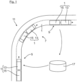
- a vehicle 3 driving on a road 1 is shown in three driving situations 5, 7, 9.
- a first driving situation 5 the vehicle 1 is located, viewed in the direction of travel, directly in front of a curve 11 of the road 1.
- a later second driving situation 7 the vehicle 1 is in the middle of the curve 11, so that the curve 11 is driven through by the vehicle 1.
- a later third driving situation 9 the vehicle 1 has driven through the curve 11, so that the curve 11 is located behind the vehicle 1 in the direction of travel.
- the vehicle 1 is shown here by way of example by a A train combination is formed which consists of a towing vehicle 13 and a trailer 15 coupled to the towing vehicle 13.
- the vehicle 1 is connected to a schematically indicated evaluation station 17 for data transmission.
- This evaluation station 17 can be formed by a cloud server, for example.
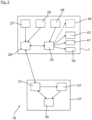
- the vehicle 1 and the evaluation station 17 together form a system 19 ( Fig. 2 ) to operate the vehicle 1.
- the structure of this system 19 is described below using Figure 2 explained in more detail:
- the vehicle 1 has a trip information determination device 25, by means of which the current position and the current route of the vehicle 1 are continuously or continuously determined as trip information.
- the vehicle 1 also has a state determination device 27, by means of which the current state of the vehicle is also continuously or continuously determined. Specifically, the current speed of the vehicle 1, the currently selected gear of a vehicle transmission and the amount of fuel stored in a fuel tank of the vehicle 1 are continuously determined by means of the state determination device 27.
- the determination of the current trip information and the current vehicle state data can be activated automatically, for example, when the vehicle 1 is started.
- the trip information determination device 25 and the status determination device 27 of the vehicle 1 are connected to a transmitting and receiving device 29 of the vehicle for data transmission.
- the transmitting and receiving device 29 By means of the transmitting and receiving device 29, the current trip information determined by means of the trip information determination device 25 and the current vehicle status data determined by means of the status determination device 27 are continuously or continuously transmitted to a transmitting and receiving device 31 of the evaluation station 17, which is connected to the vehicle-side transmitting and receiving device 29 for data transmission.
- This transmission of the current trip information and the current vehicle status data to the evaluation station 17 can be activated, for example, when a driver of the vehicle 1 activates a speed control system or cruise control of the vehicle 1.
- vehicle information stored in a control unit 33 of the vehicle 1 is also transmitted to the evaluation station 17 by means of the vehicle-side transmitting and receiving device 29.
- This vehicle information stored in the control unit 33 is here, for example, represented by the type of vehicle, the current loading state of the Vehicle 1 and the engine of the vehicle 1.
- This vehicle information can also be transmitted to the evaluation station 17 when a cruise control of the vehicle 1 is activated.
- the evaluation station 17 has a driving strategy determination device 35 which is connected to the transmitting and receiving device 31 for data transmission.
- This driving strategy determination device 35 is also connected to a storage device 37 of the evaluation station 17 in which map data or road data are stored. Based on the driving information of the vehicle 1 transmitted to the evaluation station 17 and on the road data stored in the storage device 37, the driving strategy determination device 35 continuously or continuously determines whether there is a curve with a defined curve course directly in front of the vehicle 1 in the direction of travel.
- the driving strategy determination device 35 determines an optimal, in particular an energy-consumption-optimized, driving strategy for driving through the curve based on experience data stored in the storage device 37 for at least one passage through a curve with an identical or similar curve course with a vehicle, preferably with the same or a similar vehicle, and based on the transmitted vehicle information of the vehicle 1.
- the determined driving strategy is then transmitted to the transmitting and receiving device 29 and thus to the vehicle 1 by means of the transmitting and receiving device 31 of the evaluation station 17 before driving through the curve.
- Figure 1 This transmission of the optimal driving strategy takes place in the first driving situation 5 of the vehicle 1 before the curve 11.
- the determined driving strategy is then forwarded from the vehicle-side transmitting and receiving device 29 to the control unit 33 of the vehicle 1.
- the control unit 33 By means of the control unit 33, an internal combustion engine 39 of the vehicle 1, a transmission 41 of the vehicle 1 and a recuperation braking system 43 of the vehicle 1 are then controlled automatically in such a way that the vehicle 1 adheres as far as possible to the determined optimal driving strategy for driving through the curve 11.
- the control unit 33 can also control a screen 45 of the vehicle 1 indicated with dashed lines, so that the determined driving strategy is displayed to a driver of the vehicle 1 on the screen 45.
- the vehicle 1 here also has, for example, an actuating device 46 that can be actuated by the driver of the vehicle 1, for example a button and/or a switch, by means of which the automatic control of the internal combustion engine 39, the transmission 41 and the recuperation braking system 43 of the vehicle 1 can be deactivated and activated.
- an actuating device 46 that can be actuated by the driver of the vehicle 1, for example a button and/or a switch, by means of which the automatic control of the internal combustion engine 39, the transmission 41 and the recuperation braking system 43 of the vehicle 1 can be deactivated and activated.
- vehicle condition data determined during the curve by means of the condition determination device 27 are also transmitted to the evaluation station 17 by means of the vehicle-side transmitting and receiving device 29.
- vehicle condition data are formed here, for example, by the speed curve of the vehicle 1 during the curve, by the at least one selected gear of the vehicle transmission 41 during the curve, by the acceleration curve of the vehicle 1 during the curve and by the fuel consumption of the vehicle 1 during the curve.
- the vehicle status data determined during cornering are then forwarded to the storage device 37 of the evaluation station 17, which is connected to the transmitting and receiving device 31 for data transmission, and stored there as experience data.
- Figure 1 The vehicle status data determined during cornering are transmitted from the vehicle 1 to the evaluation station 17 in the third driving situation 9 of the vehicle.
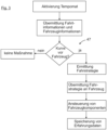
- FIG. 3 a flow chart is shown, which summarizes the process according to the invention: After the vehicle-side cruise control is activated, the current driving information, the current vehicle status data as vehicle information and the vehicle information stored in the control unit 33 are transmitted from the vehicle 1 to the evaluation station 17.
- the driving strategy determination device 35 of the evaluation station 17 then continuously determines, according to the decision diamond 47, whether there is a curve with a defined curve course in front of the vehicle 1 in the direction of travel. If there is such a curve in front of the vehicle 1, an optimal driving strategy for driving through this curve is determined. This driving strategy is then transmitted from the evaluation station 17 to the vehicle 1 before driving through the curve.
- control unit 33 is used to control vehicle components, in this case the internal combustion engine 39, the vehicle transmission 41 and the recuperation braking system 43 of the vehicle 1, to comply with the determined driving strategy.
- vehicle components in this case the internal combustion engine 39, the vehicle transmission 41 and the recuperation braking system 43 of the vehicle 1, to comply with the determined driving strategy.
- the vehicle status data determined during the curve are then transmitted to the evaluation station 17 and stored there as experience data.
Landscapes
- Engineering & Computer Science (AREA)
- Automation & Control Theory (AREA)
- Transportation (AREA)
- Mechanical Engineering (AREA)
- Radar, Positioning & Navigation (AREA)
- Remote Sensing (AREA)
- Chemical & Material Sciences (AREA)
- Combustion & Propulsion (AREA)
- Physics & Mathematics (AREA)
- General Physics & Mathematics (AREA)
- Aviation & Aerospace Engineering (AREA)
- Human Computer Interaction (AREA)
- Mathematical Physics (AREA)
- Traffic Control Systems (AREA)
- Control Of Vehicle Engines Or Engines For Specific Uses (AREA)
- Control Of Driving Devices And Active Controlling Of Vehicle (AREA)
- Hybrid Electric Vehicles (AREA)
- Control Of Transmission Device (AREA)
- Electric Propulsion And Braking For Vehicles (AREA)
Claims (14)
- Procédé permettant de faire fonctionner un véhicule, dans lequel le véhicule (1) présente un dispositif de détermination d'informations de trajet (25) au moyen duquel au moins la position actuelle du véhicule (1) en mouvement est déterminée en continu comme une information de trajet actuelle,dans lequel le véhicule (1) présente un dispositif d'émission et de réception (29) au moyen duquel les informations de trajet actuelles déterminées sont transmises conjointement avec des informations de véhicule à un poste d'évaluation (17),dans lequel un dispositif de détermination de stratégie de conduite (35) du poste d'évaluation (17) détecte d'abord à l'aide des informations de trajet transmises et à l'aide de données cartographiques stockées dans un dispositif de stockage (37) du poste d'évaluation si un virage (11) se trouve devant le véhicule (1) dans le sens de la marche,dans lequel, dans la mesure où le dispositif de détermination de stratégie de conduite (35) détecte un virage (11), le dispositif de détermination de stratégie de conduite (35) détermine une stratégie de conduite pour le passage du virage (11), etdans lequel la stratégie de conduite déterminée est transmise par le poste d'évaluation (17) au dispositif d'émission et de réception (29) côté véhicule et donc au véhicule (1),caractérisé en ce qu'à l'aide de données empiriques stockées dans le dispositif de stockage (37) pour au moins un passage d'un virage ayant un tracé de virage identique ou similaire avec le véhicule (1) ainsi qu'à l'aide des informations de véhicule transmises, le dispositif de détermination de stratégie de conduite (35) détermine une stratégie de conduite optimale en consommation d'énergie pour le passage du virage, eten ce que le dispositif de détermination de stratégie de conduite (35) détermine à l'aide des données cartographiques stockées dans le dispositif de stockage (37) le tracé de virage du virage (11) détecté, et en ce que le tracé de virage déterminé est pris en compte lors de la détermination de la stratégie de conduite optimale en consommation d'énergie.
- Procédé selon la revendication 1, caractérisé en ce qu'au moins un composant d'entraînement du véhicule (1) est piloté automatiquement au moyen d'un appareil de commande (33) du véhicule (1) pour respecter la stratégie de conduite transmise au véhicule (1), dans lequel il est prévu de préférence que ledit au moins un composant d'entraînement soit formé par un moteur à combustion interne (39) du véhicule (1) et/ou par une transmission de véhicule (41) et/ou par une machine électrique du véhicule (1).
- Procédé selon la revendication 1 ou 2, caractérisé en ce qu'au moins un système de freinage du véhicule (1) est piloté automatiquement au moyen d'un appareil de commande (33) du véhicule (1) pour respecter la stratégie de conduite transmise au véhicule (1), dans lequel il est prévu de préférence que ledit au moins un système de freinage soit formé par un système de freinage à récupération (43) du véhicule (1).
- Procédé selon la revendication 2 ou 3, caractérisé en ce que le véhicule (1) présente un dispositif d'actionnement (46) pouvant être actionné par un conducteur du véhicule, en particulier un bouton et/ou un commutateur, au moyen duquel le pilotage automatique dudit au moins un composant d'entraînement et/ou dudit au moins un système de freinage peut être désactivé, pouvant en particulier être désactivé et activé.
- Procédé selon l'une quelconque des revendications précédentes, caractérisé en ce que la stratégie de conduite transmise au véhicule (1) est affichée pour un conducteur du véhicule (1) au moyen d'un dispositif d'affichage (45), en particulier par un écran.
- Procédé selon l'une quelconque des revendications précédentes, caractérisé en ce que les informations de véhicule transmises au poste d'évaluation (17) sont formées par des données d'état du véhicule qui sont déterminées au moyen d'un dispositif de détermination d'état (27) du véhicule.
- Procédé selon la revendication 6, caractérisé en ce que les données d'état du véhicule actuelles transmises sont formées par la vitesse actuelle du véhicule (1) et/ou le rapport sélectionné actuellement d'une transmission de véhicule (41) et/ou par la quantité d'énergie électrique accumulée actuellement au moyen d'un dispositif d'accumulation d'énergie du véhicule (1) et/ou par la quantité de carburant stockée dans un réservoir de carburant du véhicule (1).
- Procédé selon la revendication 6 ou 7, caractérisé en ce que pendant le fonctionnement du véhicule, les données d'état du véhicule actuelles déterminées sont transmises en continu au poste d'évaluation (17) au moyen du dispositif d'émission et de réception (29) côté véhicule.
- Procédé selon l'une quelconque des revendications précédentes, caractérisé en ce que les informations de véhicule transmises au poste d'évaluation (17) sont formées par le type de véhicule et/ou par l'état de chargement actuel du véhicule (1) et/ou par la motorisation du véhicule (1).
- Procédé selon l'une quelconque des revendications précédentes, caractérisé en ce que pendant le passage du virage (11) détecté, le dispositif de détermination d'état (27) du véhicule (1) détermine des données d'état du véhicule actuelles, et en ce que les données d'état du véhicule déterminées sont transmises au moyen du dispositif d'émission et de réception (29) au poste d'évaluation (17) et y sont stockées en tant que données empiriques dans le dispositif de stockage (37) du poste d'évaluation (17).
- Procédé selon la revendication 10, caractérisé en ce que les données d'état du véhicule sont formées par la courbe de vitesse du véhicule (1) et/ou par ledit au moins un rapport sélectionné d'une transmission de véhicule (41) et/ou par la courbe d'accélération du véhicule (1) et/ou par la consommation d'énergie du véhicule (1), en particulier par la consommation de carburant du véhicule (1), pendant le passage d'un virage.
- Procédé selon l'une quelconque des revendications précédentes, caractérisé en ce que, dans la mesure où des données empiriques pour au moins un passage du virage (11) détecté avec un véhicule similaire sont stockées dans le dispositif de stockage (37) du poste d'évaluation (17), ces données empiriques stockées sont prises en compte lors de la détermination de la stratégie de conduite optimale.
- Système permettant d'exécuter un procédé selon l'une quelconque des revendications précédentes.
- Véhicule, en particulier véhicule utilitaire, permettant d'exécuter un procédé selon l'une quelconque des revendications 1 à 12.
Applications Claiming Priority (1)
| Application Number | Priority Date | Filing Date | Title |
|---|---|---|---|
| DE102017000608.3A DE102017000608A1 (de) | 2017-01-24 | 2017-01-24 | Verfahren zum Betreiben eines Fahrzeugs, insbesondere eines Nutzfahrzeugs |
Publications (2)
| Publication Number | Publication Date |
|---|---|
| EP3360741A1 EP3360741A1 (fr) | 2018-08-15 |
| EP3360741B1 true EP3360741B1 (fr) | 2025-03-05 |
Family
ID=61005722
Family Applications (1)
| Application Number | Title | Priority Date | Filing Date |
|---|---|---|---|
| EP18152016.4A Active EP3360741B1 (fr) | 2017-01-24 | 2018-01-17 | Procédé de fonctionnement d'un véhicule, en particulier un véhicule utilitaire |
Country Status (5)
| Country | Link |
|---|---|
| US (1) | US11009369B2 (fr) |
| EP (1) | EP3360741B1 (fr) |
| CN (1) | CN108340923B (fr) |
| DE (1) | DE102017000608A1 (fr) |
| RU (1) | RU2752702C2 (fr) |
Families Citing this family (2)
| Publication number | Priority date | Publication date | Assignee | Title |
|---|---|---|---|---|
| CN116215252B (zh) * | 2023-03-11 | 2024-03-08 | 南京农业大学 | 动态交互式新能源交通系统及其交互方法 |
| CN119636734B (zh) * | 2025-01-08 | 2025-12-05 | 中国重汽集团济南动力有限公司 | 车辆弯道控制方法、装置、设备、介质及计算机程序产品 |
Family Cites Families (51)
| Publication number | Priority date | Publication date | Assignee | Title |
|---|---|---|---|---|
| JPS55127221A (en) * | 1979-03-20 | 1980-10-01 | Daihatsu Motor Co Ltd | Driving system of vehicle |
| JP3239727B2 (ja) * | 1995-12-05 | 2001-12-17 | トヨタ自動車株式会社 | 車両の自動運転制御装置 |
| US6125325A (en) * | 1996-04-25 | 2000-09-26 | Sirf Technology, Inc. | GPS receiver with cross-track hold |
| JP4046742B2 (ja) * | 2005-07-14 | 2008-02-13 | 三菱電機株式会社 | 道路形状推定装置 |
| DE102005055744A1 (de) * | 2005-11-23 | 2007-05-24 | Robert Bosch Gmbh | Fahrerassistenzsystem für Kraftfahrzeuge |
| DE102006028277A1 (de) * | 2006-06-20 | 2007-12-27 | Robert Bosch Gmbh | Vorrichtung und Verfahren zur Kurvenvorwarnung |
| US7522069B2 (en) * | 2006-07-27 | 2009-04-21 | Vmatter Holdings, Llc | Vehicle trip logger |
| JP4254844B2 (ja) * | 2006-11-01 | 2009-04-15 | トヨタ自動車株式会社 | 走行制御計画評価装置 |
| KR101013906B1 (ko) * | 2007-12-18 | 2011-02-14 | 기아자동차주식회사 | 경제운전 안내 시스템 |
| JP4475342B2 (ja) * | 2008-03-28 | 2010-06-09 | アイシン・エィ・ダブリュ株式会社 | 道路形状推定装置、道路形状推定方法及びプログラム |
| JP5013211B2 (ja) * | 2008-08-21 | 2012-08-29 | アイシン・エィ・ダブリュ株式会社 | 運転評価システム及び運転評価プログラム |
| US20100185389A1 (en) * | 2009-01-21 | 2010-07-22 | Michael Glenn Woodard | GPS-based vehicle alert and control system |
| JP4873042B2 (ja) * | 2009-04-13 | 2012-02-08 | トヨタ自動車株式会社 | 車両制御装置および車両制御方法 |
| DE102009033752A1 (de) * | 2009-07-17 | 2011-01-27 | Volkswagen Ag | Verfahren und Vorrichtung zum Schalten verschiedener Funktionen |
| US8423273B2 (en) * | 2010-03-30 | 2013-04-16 | Honda Motor Co., Ltd. | Minimum energy route for a motor vehicle |
| JP5672822B2 (ja) * | 2010-07-29 | 2015-02-18 | トヨタ自動車株式会社 | 車両制御システム |
| DE102010048323A1 (de) | 2010-10-13 | 2012-04-19 | Man Truck & Bus Ag | Fahrerassistenzsystem und entsprechendes Betriebsverfahren zur Anzeige oder Mitteilung einer Kraftstoffeinsparungssituation zur Senkung des Kraftstoffverbrauchs eines Kraftfahrzeugs |
| JP5375805B2 (ja) * | 2010-11-26 | 2013-12-25 | トヨタ自動車株式会社 | 運転支援システム及び運転支援管理センター |
| DE102011010653A1 (de) * | 2011-02-09 | 2012-08-09 | Audi Ag | Verfahren und Warnvorrichtung zum Warnen eines Führers eines Fahrzeugs sowie Fahrzeug |
| US8700299B2 (en) * | 2011-02-24 | 2014-04-15 | Mitsubishi Electric Corporation | Navigation device, recommended speed arithmetic device, and recommended speed presentation device |
| JP5856387B2 (ja) * | 2011-05-16 | 2016-02-09 | トヨタ自動車株式会社 | 車両データの解析方法及び車両データの解析システム |
| US8583361B2 (en) * | 2011-08-24 | 2013-11-12 | Modular Mining Systems, Inc. | Guided maneuvering of a mining vehicle to a target destination |
| DE102011112990A1 (de) * | 2011-09-10 | 2013-03-14 | Ina Fischer | Automatische Fahrhilfe für Fahrzeuge |
| CN103247185B (zh) * | 2012-02-14 | 2016-01-20 | 厦门金龙联合汽车工业有限公司 | 一种车辆入弯防侧翻提醒系统和方法 |
| US9349234B2 (en) * | 2012-03-14 | 2016-05-24 | Autoconnect Holdings Llc | Vehicle to vehicle social and business communications |
| DE102012215100A1 (de) * | 2012-08-24 | 2014-02-27 | Continental Teves Ag & Co. Ohg | Verfahren und System zur Förderung eines gleichmäßigen Fahrstils |
| DE102012024859B3 (de) * | 2012-12-19 | 2014-01-09 | Audi Ag | Verfahren zum Bereitstellen einer Betriebsstrategie für ein Kraftfahrzeug |
| JP6055848B2 (ja) * | 2013-02-01 | 2016-12-27 | 日立オートモティブシステムズ株式会社 | 走行制御装置及び走行制御システム |
| US20140257686A1 (en) * | 2013-03-05 | 2014-09-11 | GM Global Technology Operations LLC | Vehicle lane determination |
| US9211891B2 (en) * | 2013-08-02 | 2015-12-15 | Inrix Inc. | Personalized vehicle driving suggestions |
| US9805521B1 (en) * | 2013-12-03 | 2017-10-31 | United Parcel Service Of America, Inc. | Systems and methods for assessing turns made by a vehicle |
| CN103927895B (zh) * | 2014-04-25 | 2015-11-11 | 清华大学 | 一种基于车路/车车通讯的车辆弯道通行辅助系统 |
| JP5855163B2 (ja) * | 2014-05-13 | 2016-02-09 | 三菱電機株式会社 | 車両用エネルギーマネジメント装置 |
| JP2016007894A (ja) * | 2014-06-23 | 2016-01-18 | トヨタ自動車株式会社 | 注意喚起装置及び走行制御装置 |
| US9242654B2 (en) * | 2014-06-27 | 2016-01-26 | International Business Machines Corporation | Determining vehicle collision risk |
| JP6421481B2 (ja) * | 2014-07-18 | 2018-11-14 | 株式会社デンソー | 遠隔制御装置およびそれを用いた遠隔制御システム |
| JP6201927B2 (ja) * | 2014-08-01 | 2017-09-27 | トヨタ自動車株式会社 | 車両制御装置 |
| JP6041979B2 (ja) * | 2014-11-27 | 2016-12-14 | 株式会社小松製作所 | 鉱山機械の管理システム、及びダンプトラック |
| JP6222477B2 (ja) * | 2014-12-03 | 2017-11-01 | マツダ株式会社 | 車両の走行ライン生成装置 |
| KR20170015115A (ko) * | 2015-07-30 | 2017-02-08 | 삼성전자주식회사 | 자율 주행 차량 및 자율 주행 차량 제어 방법 |
| DE102016223555B4 (de) * | 2015-11-30 | 2024-06-06 | Ford Global Technologies, Llc | Verfahren und System zum Betreiben eines Fahrzeugs mit Verbrennungsmotor sowie Kraftfahrzeug und Netzwerk zur Versorgung elektrisch angetriebener Fahrzeuge |
| DE102015015923A1 (de) | 2015-12-09 | 2017-06-14 | Wabco Gmbh | Verfahren zum adaptiven Regeln einer Fahrzeuggeschwindigkeit in einem Fahrzeug sowie Geschwindigkeitsregelanlage zum Durchführen des Verfahrens |
| CN105564429A (zh) * | 2016-01-29 | 2016-05-11 | 深圳市美好幸福生活安全系统有限公司 | 行车安全预警的方法及装置 |
| US9672738B1 (en) * | 2016-02-02 | 2017-06-06 | Allstate Insurance Company | Designing preferred vehicle routes based on driving scores from other vehicles |
| US9896089B2 (en) * | 2016-04-07 | 2018-02-20 | Ford Global Technologies, Llc | Methods and systems for adjusting engine operation based on weather data |
| US9672734B1 (en) * | 2016-04-08 | 2017-06-06 | Sivalogeswaran Ratnasingam | Traffic aware lane determination for human driver and autonomous vehicle driving system |
| US10502574B2 (en) * | 2016-09-20 | 2019-12-10 | Waymo Llc | Devices and methods for a sensor platform of a vehicle |
| DE102016218070B4 (de) * | 2016-09-21 | 2024-09-26 | Vitesco Technologies GmbH | Bestimmung des optimalen Beginns der Verzögerungsphase im Backend |
| US10377260B2 (en) * | 2017-01-13 | 2019-08-13 | Uber Technologies, Inc. | Charge control system for mobile energy storage fleet |
| US20180364739A1 (en) * | 2017-06-19 | 2018-12-20 | Cnh Industrial America Llc | Choreographer system for autonomous off-road vehicles |
| US10684372B2 (en) * | 2017-10-03 | 2020-06-16 | Uatc, Llc | Systems, devices, and methods for autonomous vehicle localization |
-
2017
- 2017-01-24 DE DE102017000608.3A patent/DE102017000608A1/de active Pending
-
2018
- 2018-01-17 EP EP18152016.4A patent/EP3360741B1/fr active Active
- 2018-01-22 US US15/876,851 patent/US11009369B2/en active Active
- 2018-01-23 RU RU2018102527A patent/RU2752702C2/ru active
- 2018-01-24 CN CN201810068362.2A patent/CN108340923B/zh active Active
Also Published As
| Publication number | Publication date |
|---|---|
| RU2018102527A (ru) | 2019-07-24 |
| US20180209813A1 (en) | 2018-07-26 |
| RU2752702C2 (ru) | 2021-07-30 |
| RU2018102527A3 (fr) | 2021-05-28 |
| US11009369B2 (en) | 2021-05-18 |
| CN108340923B (zh) | 2023-09-05 |
| CN108340923A (zh) | 2018-07-31 |
| EP3360741A1 (fr) | 2018-08-15 |
| DE102017000608A1 (de) | 2018-07-26 |
Similar Documents
| Publication | Publication Date | Title |
|---|---|---|
| EP2010423B1 (fr) | Dispositif de regulation de la vitesse et vehicule automobile equipe d'un tel dispositif de regulation de la vitesse | |
| DE102008015046A1 (de) | Verfahren und Vorrichtung zur prädiktiven Steuerung und/oder Regelung eines Hybridantriebs in einem Kraftfahrzeug sowie Hybridfahrzeug | |
| DE102010023198A1 (de) | Vorrichtung und Verfahren zum Steuern des Fahrverhaltens eines Fahrzeugs bei Annäherung an einen Haltepunkt | |
| DE102014019543A1 (de) | Verfahren und Vorrichtung zum Betrieb eines Antriebsstrangs eines Fahrzeugs | |
| DE102007054453A1 (de) | Verfahren zur Ermittlung einer Wahrscheinlichkeit für das Stattfinden eines bevorstehenden Überholvorgangs | |
| DE102012017526A1 (de) | Verfahren zum Betrieb eines Fahrzeuges | |
| DE102011007034A1 (de) | Vorrichtung und Verfahren zum Betreiben eines Fahrzeugs | |
| DE102010039642A1 (de) | Einstellung des Schleppmoments eines Kraftfahrzeugs-Antriebsstrangs für den Schubbetrieb | |
| DE102016011411A1 (de) | Verfahren zum Betreiben eines Antriebsstrangs eines Kraftfahrzeugs | |
| DE102016012414B4 (de) | Verfahren zum Steuern eines Antriebsstrangs eines Kraftfahrzeugs | |
| DE112018004528T5 (de) | Fahrkontrollvorrichtung, fahrzeug und fahrkontrollverfahren | |
| DE102010026769A1 (de) | Verfahren und Vorrichtung zum Betrieb eines Fahrzeugs | |
| DE102009057393A1 (de) | Verfahren zum Steuern des Betriebs eines Fahrzeugs | |
| DE102007005030A1 (de) | Verfahren für die Steuerung eines Fahrzeugs mit Hybridantrieb | |
| DE102008054663A1 (de) | Verfahren zum Betreiben eines Antriebsstrangs | |
| DE19914428C1 (de) | Antriebsanordnung für ein Kraftfahrzeug | |
| EP3360741B1 (fr) | Procédé de fonctionnement d'un véhicule, en particulier un véhicule utilitaire | |
| EP3360744B1 (fr) | Procédé de fonctionnement d'un véhicule, en particulier un véhicule utilitaire | |
| EP3141415B1 (fr) | Procédé et dispositif d'assistance de conducteur d'un véhicule lors du freinage d'un véhicule automobile | |
| DE102014201765A1 (de) | Verfahren zum Betreiben eines Antriebsstrangs eines Hybridfahrzeuges | |
| DE102010010557A1 (de) | Vorrichtung und Verfahren zum Betrieb eines Fahrerassistenzsystems für ein Fahrzeug | |
| EP4377176B1 (fr) | Procédé, dispositif de traitement de données et logiciel pour déterminer une stratégie de décélération pour un véhicule | |
| DE102019004368A1 (de) | Verfahren und Vorrichtung zum Steuern einer Fahrzeuggeschwindigkeit | |
| DE102017221887A1 (de) | Verfahren zum Betreiben eines Antriebsstrangs eines Kraftfahrzeuges | |
| DE102023107814A1 (de) | Verfahren und Steueranordnung zur Steuerung eines Fahrzeugs während einer Geschwindigkeitsreduzierung |
Legal Events
| Date | Code | Title | Description |
|---|---|---|---|
| PUAI | Public reference made under article 153(3) epc to a published international application that has entered the european phase |
Free format text: ORIGINAL CODE: 0009012 |
|
| STAA | Information on the status of an ep patent application or granted ep patent |
Free format text: STATUS: THE APPLICATION HAS BEEN PUBLISHED |
|
| AK | Designated contracting states |
Kind code of ref document: A1 Designated state(s): AL AT BE BG CH CY CZ DE DK EE ES FI FR GB GR HR HU IE IS IT LI LT LU LV MC MK MT NL NO PL PT RO RS SE SI SK SM TR |
|
| AX | Request for extension of the european patent |
Extension state: BA ME |
|
| STAA | Information on the status of an ep patent application or granted ep patent |
Free format text: STATUS: REQUEST FOR EXAMINATION WAS MADE |
|
| 17P | Request for examination filed |
Effective date: 20190215 |
|
| RBV | Designated contracting states (corrected) |
Designated state(s): AL AT BE BG CH CY CZ DE DK EE ES FI FR GB GR HR HU IE IS IT LI LT LU LV MC MK MT NL NO PL PT RO RS SE SI SK SM TR |
|
| RAP1 | Party data changed (applicant data changed or rights of an application transferred) |
Owner name: MAN TRUCK & BUS SE |
|
| STAA | Information on the status of an ep patent application or granted ep patent |
Free format text: STATUS: EXAMINATION IS IN PROGRESS |
|
| 17Q | First examination report despatched |
Effective date: 20211027 |
|
| GRAP | Despatch of communication of intention to grant a patent |
Free format text: ORIGINAL CODE: EPIDOSNIGR1 |
|
| STAA | Information on the status of an ep patent application or granted ep patent |
Free format text: STATUS: GRANT OF PATENT IS INTENDED |
|
| RIC1 | Information provided on ipc code assigned before grant |
Ipc: G05D 1/00 20060101ALI20240909BHEP Ipc: B60W 50/00 20060101ALI20240909BHEP Ipc: B60W 50/14 20120101ALI20240909BHEP Ipc: B60W 30/18 20120101ALI20240909BHEP Ipc: B60W 30/045 20120101ALI20240909BHEP Ipc: B60W 20/00 20160101ALI20240909BHEP Ipc: B60W 10/18 20120101ALI20240909BHEP Ipc: B60W 10/04 20060101ALI20240909BHEP Ipc: B60W 10/00 20060101AFI20240909BHEP |
|
| INTG | Intention to grant announced |
Effective date: 20240923 |
|
| GRAS | Grant fee paid |
Free format text: ORIGINAL CODE: EPIDOSNIGR3 |
|
| GRAA | (expected) grant |
Free format text: ORIGINAL CODE: 0009210 |
|
| STAA | Information on the status of an ep patent application or granted ep patent |
Free format text: STATUS: THE PATENT HAS BEEN GRANTED |
|
| AK | Designated contracting states |
Kind code of ref document: B1 Designated state(s): AL AT BE BG CH CY CZ DE DK EE ES FI FR GB GR HR HU IE IS IT LI LT LU LV MC MK MT NL NO PL PT RO RS SE SI SK SM TR |
|
| REG | Reference to a national code |
Ref country code: GB Ref legal event code: FG4D Free format text: NOT ENGLISH |
|
| REG | Reference to a national code |
Ref country code: CH Ref legal event code: EP |
|
| REG | Reference to a national code |
Ref country code: IE Ref legal event code: FG4D Free format text: LANGUAGE OF EP DOCUMENT: GERMAN |
|
| REG | Reference to a national code |
Ref country code: DE Ref legal event code: R096 Ref document number: 502018015616 Country of ref document: DE |
|
| REG | Reference to a national code |
Ref country code: NL Ref legal event code: FP |
|
| REG | Reference to a national code |
Ref country code: SE Ref legal event code: TRGR |
|
| PG25 | Lapsed in a contracting state [announced via postgrant information from national office to epo] |
Ref country code: RS Free format text: LAPSE BECAUSE OF FAILURE TO SUBMIT A TRANSLATION OF THE DESCRIPTION OR TO PAY THE FEE WITHIN THE PRESCRIBED TIME-LIMIT Effective date: 20250605 |
|
| PG25 | Lapsed in a contracting state [announced via postgrant information from national office to epo] |
Ref country code: FI Free format text: LAPSE BECAUSE OF FAILURE TO SUBMIT A TRANSLATION OF THE DESCRIPTION OR TO PAY THE FEE WITHIN THE PRESCRIBED TIME-LIMIT Effective date: 20250305 |
|
| PG25 | Lapsed in a contracting state [announced via postgrant information from national office to epo] |
Ref country code: ES Free format text: LAPSE BECAUSE OF FAILURE TO SUBMIT A TRANSLATION OF THE DESCRIPTION OR TO PAY THE FEE WITHIN THE PRESCRIBED TIME-LIMIT Effective date: 20250305 |
|
| REG | Reference to a national code |
Ref country code: LT Ref legal event code: MG9D |
|
| PG25 | Lapsed in a contracting state [announced via postgrant information from national office to epo] |
Ref country code: NO Free format text: LAPSE BECAUSE OF FAILURE TO SUBMIT A TRANSLATION OF THE DESCRIPTION OR TO PAY THE FEE WITHIN THE PRESCRIBED TIME-LIMIT Effective date: 20250605 |
|
| PG25 | Lapsed in a contracting state [announced via postgrant information from national office to epo] |
Ref country code: HR Free format text: LAPSE BECAUSE OF FAILURE TO SUBMIT A TRANSLATION OF THE DESCRIPTION OR TO PAY THE FEE WITHIN THE PRESCRIBED TIME-LIMIT Effective date: 20250305 |
|
| PG25 | Lapsed in a contracting state [announced via postgrant information from national office to epo] |
Ref country code: LV Free format text: LAPSE BECAUSE OF FAILURE TO SUBMIT A TRANSLATION OF THE DESCRIPTION OR TO PAY THE FEE WITHIN THE PRESCRIBED TIME-LIMIT Effective date: 20250305 |
|
| PG25 | Lapsed in a contracting state [announced via postgrant information from national office to epo] |
Ref country code: GR Free format text: LAPSE BECAUSE OF FAILURE TO SUBMIT A TRANSLATION OF THE DESCRIPTION OR TO PAY THE FEE WITHIN THE PRESCRIBED TIME-LIMIT Effective date: 20250606 Ref country code: BG Free format text: LAPSE BECAUSE OF FAILURE TO SUBMIT A TRANSLATION OF THE DESCRIPTION OR TO PAY THE FEE WITHIN THE PRESCRIBED TIME-LIMIT Effective date: 20250305 |
|
| PG25 | Lapsed in a contracting state [announced via postgrant information from national office to epo] |
Ref country code: SM Free format text: LAPSE BECAUSE OF FAILURE TO SUBMIT A TRANSLATION OF THE DESCRIPTION OR TO PAY THE FEE WITHIN THE PRESCRIBED TIME-LIMIT Effective date: 20250305 |
|
| PG25 | Lapsed in a contracting state [announced via postgrant information from national office to epo] |
Ref country code: PT Free format text: LAPSE BECAUSE OF FAILURE TO SUBMIT A TRANSLATION OF THE DESCRIPTION OR TO PAY THE FEE WITHIN THE PRESCRIBED TIME-LIMIT Effective date: 20250707 |
|
| PG25 | Lapsed in a contracting state [announced via postgrant information from national office to epo] |
Ref country code: PL Free format text: LAPSE BECAUSE OF FAILURE TO SUBMIT A TRANSLATION OF THE DESCRIPTION OR TO PAY THE FEE WITHIN THE PRESCRIBED TIME-LIMIT Effective date: 20250305 |
|
| PG25 | Lapsed in a contracting state [announced via postgrant information from national office to epo] |
Ref country code: CZ Free format text: LAPSE BECAUSE OF FAILURE TO SUBMIT A TRANSLATION OF THE DESCRIPTION OR TO PAY THE FEE WITHIN THE PRESCRIBED TIME-LIMIT Effective date: 20250305 Ref country code: EE Free format text: LAPSE BECAUSE OF FAILURE TO SUBMIT A TRANSLATION OF THE DESCRIPTION OR TO PAY THE FEE WITHIN THE PRESCRIBED TIME-LIMIT Effective date: 20250305 |
|
| PG25 | Lapsed in a contracting state [announced via postgrant information from national office to epo] |
Ref country code: RO Free format text: LAPSE BECAUSE OF FAILURE TO SUBMIT A TRANSLATION OF THE DESCRIPTION OR TO PAY THE FEE WITHIN THE PRESCRIBED TIME-LIMIT Effective date: 20250305 |
|
| PG25 | Lapsed in a contracting state [announced via postgrant information from national office to epo] |
Ref country code: SK Free format text: LAPSE BECAUSE OF FAILURE TO SUBMIT A TRANSLATION OF THE DESCRIPTION OR TO PAY THE FEE WITHIN THE PRESCRIBED TIME-LIMIT Effective date: 20250305 |
|
| PG25 | Lapsed in a contracting state [announced via postgrant information from national office to epo] |
Ref country code: IS Free format text: LAPSE BECAUSE OF FAILURE TO SUBMIT A TRANSLATION OF THE DESCRIPTION OR TO PAY THE FEE WITHIN THE PRESCRIBED TIME-LIMIT Effective date: 20250705 |
|
| REG | Reference to a national code |
Ref country code: DE Ref legal event code: R097 Ref document number: 502018015616 Country of ref document: DE |
|
| PLBE | No opposition filed within time limit |
Free format text: ORIGINAL CODE: 0009261 |
|
| STAA | Information on the status of an ep patent application or granted ep patent |
Free format text: STATUS: NO OPPOSITION FILED WITHIN TIME LIMIT |
|
| PG25 | Lapsed in a contracting state [announced via postgrant information from national office to epo] |
Ref country code: DK Free format text: LAPSE BECAUSE OF FAILURE TO SUBMIT A TRANSLATION OF THE DESCRIPTION OR TO PAY THE FEE WITHIN THE PRESCRIBED TIME-LIMIT Effective date: 20250305 |
|
| REG | Reference to a national code |
Ref country code: CH Ref legal event code: L10 Free format text: ST27 STATUS EVENT CODE: U-0-0-L10-L00 (AS PROVIDED BY THE NATIONAL OFFICE) Effective date: 20260114 |
|
| 26N | No opposition filed |
Effective date: 20251208 |
|
| PGFP | Annual fee paid to national office [announced via postgrant information from national office to epo] |
Ref country code: NL Payment date: 20260122 Year of fee payment: 9 |
|
| PGFP | Annual fee paid to national office [announced via postgrant information from national office to epo] |
Ref country code: SE Payment date: 20260126 Year of fee payment: 9 |
|
| PGFP | Annual fee paid to national office [announced via postgrant information from national office to epo] |
Ref country code: DE Payment date: 20260127 Year of fee payment: 9 |
|
| PGFP | Annual fee paid to national office [announced via postgrant information from national office to epo] |
Ref country code: IT Payment date: 20260123 Year of fee payment: 9 |
|
| PGFP | Annual fee paid to national office [announced via postgrant information from national office to epo] |
Ref country code: FR Payment date: 20260127 Year of fee payment: 9 |