EP3360835A2 - Geschwindigkeitserkennungsmittel für aufzug oder gegengewicht - Google Patents
Geschwindigkeitserkennungsmittel für aufzug oder gegengewicht Download PDFInfo
- Publication number
- EP3360835A2 EP3360835A2 EP17206823.1A EP17206823A EP3360835A2 EP 3360835 A2 EP3360835 A2 EP 3360835A2 EP 17206823 A EP17206823 A EP 17206823A EP 3360835 A2 EP3360835 A2 EP 3360835A2
- Authority
- EP
- European Patent Office
- Prior art keywords
- guide member
- mounting plate
- guide rail
- elevator car
- guide
- Prior art date
- Legal status (The legal status is an assumption and is not a legal conclusion. Google has not performed a legal analysis and makes no representation as to the accuracy of the status listed.)
- Withdrawn
Links
- 238000001514 detection method Methods 0.000 title claims abstract description 24
- 230000007246 mechanism Effects 0.000 claims abstract description 21
- 230000036316 preload Effects 0.000 claims abstract description 17
- 238000004891 communication Methods 0.000 claims abstract description 14
- 238000006073 displacement reaction Methods 0.000 claims description 3
- 230000003287 optical effect Effects 0.000 claims description 3
- 238000013461 design Methods 0.000 description 3
- 230000010354 integration Effects 0.000 description 2
- 230000013011 mating Effects 0.000 description 2
- 238000005259 measurement Methods 0.000 description 2
- 238000000034 method Methods 0.000 description 2
- 238000012986 modification Methods 0.000 description 2
- 230000004048 modification Effects 0.000 description 2
- 230000005355 Hall effect Effects 0.000 description 1
- 230000004075 alteration Effects 0.000 description 1
- 238000010586 diagram Methods 0.000 description 1
- 230000005611 electricity Effects 0.000 description 1
- 230000008030 elimination Effects 0.000 description 1
- 238000003379 elimination reaction Methods 0.000 description 1
- 238000012545 processing Methods 0.000 description 1
- 230000001737 promoting effect Effects 0.000 description 1
- 230000001960 triggered effect Effects 0.000 description 1
Images

Classifications
-
- B—PERFORMING OPERATIONS; TRANSPORTING
- B66—HOISTING; LIFTING; HAULING
- B66B—ELEVATORS; ESCALATORS OR MOVING WALKWAYS
- B66B5/00—Applications of checking, fault-correcting, or safety devices in elevators
- B66B5/02—Applications of checking, fault-correcting, or safety devices in elevators responsive to abnormal operating conditions
- B66B5/04—Applications of checking, fault-correcting, or safety devices in elevators responsive to abnormal operating conditions for detecting excessive speed
- B66B5/044—Mechanical overspeed governors
-
- B—PERFORMING OPERATIONS; TRANSPORTING
- B66—HOISTING; LIFTING; HAULING
- B66B—ELEVATORS; ESCALATORS OR MOVING WALKWAYS
- B66B5/00—Applications of checking, fault-correcting, or safety devices in elevators
- B66B5/02—Applications of checking, fault-correcting, or safety devices in elevators responsive to abnormal operating conditions
- B66B5/04—Applications of checking, fault-correcting, or safety devices in elevators responsive to abnormal operating conditions for detecting excessive speed
- B66B5/06—Applications of checking, fault-correcting, or safety devices in elevators responsive to abnormal operating conditions for detecting excessive speed electrical
-
- B—PERFORMING OPERATIONS; TRANSPORTING
- B66—HOISTING; LIFTING; HAULING
- B66B—ELEVATORS; ESCALATORS OR MOVING WALKWAYS
- B66B5/00—Applications of checking, fault-correcting, or safety devices in elevators
- B66B5/02—Applications of checking, fault-correcting, or safety devices in elevators responsive to abnormal operating conditions
- B66B5/04—Applications of checking, fault-correcting, or safety devices in elevators responsive to abnormal operating conditions for detecting excessive speed
-
- B—PERFORMING OPERATIONS; TRANSPORTING
- B66—HOISTING; LIFTING; HAULING
- B66B—ELEVATORS; ESCALATORS OR MOVING WALKWAYS
- B66B5/00—Applications of checking, fault-correcting, or safety devices in elevators
- B66B5/02—Applications of checking, fault-correcting, or safety devices in elevators responsive to abnormal operating conditions
- B66B5/16—Braking or catch devices operating between cars, cages, or skips and fixed guide elements or surfaces in hoistway or well
- B66B5/18—Braking or catch devices operating between cars, cages, or skips and fixed guide elements or surfaces in hoistway or well and applying frictional retarding forces
-
- B—PERFORMING OPERATIONS; TRANSPORTING
- B66—HOISTING; LIFTING; HAULING
- B66B—ELEVATORS; ESCALATORS OR MOVING WALKWAYS
- B66B5/00—Applications of checking, fault-correcting, or safety devices in elevators
- B66B5/02—Applications of checking, fault-correcting, or safety devices in elevators responsive to abnormal operating conditions
- B66B5/16—Braking or catch devices operating between cars, cages, or skips and fixed guide elements or surfaces in hoistway or well
- B66B5/18—Braking or catch devices operating between cars, cages, or skips and fixed guide elements or surfaces in hoistway or well and applying frictional retarding forces
- B66B5/22—Braking or catch devices operating between cars, cages, or skips and fixed guide elements or surfaces in hoistway or well and applying frictional retarding forces by means of linearly-movable wedges
-
- B—PERFORMING OPERATIONS; TRANSPORTING
- B66—HOISTING; LIFTING; HAULING
- B66B—ELEVATORS; ESCALATORS OR MOVING WALKWAYS
- B66B7/00—Other common features of elevators
- B66B7/02—Guideways; Guides
- B66B7/04—Riding means, e.g. Shoes, Rollers, between car and guiding means, e.g. rails, ropes
- B66B7/048—Riding means, e.g. Shoes, Rollers, between car and guiding means, e.g. rails, ropes including passive attenuation system for shocks, vibrations
Definitions
- the present disclosure is generally related to braking and/or safety systems and, more specifically, to a speed detection apparatus for an electronic safety actuator for an elevator.
- Some machines such as an elevator system, include a safety system to stop the machine when it rotates at excessive speeds or the elevator cab travels at excessive speeds.
- a safety system to stop the machine when it rotates at excessive speeds or the elevator cab travels at excessive speeds.
- a speed detection device for a braking device in an elevator system including an elevator car and a guide rail operable in a hoistway.
- the speed detection device includes a safety actuation device having a first guide member disposed on a mounting plate and a second guide member disposed on the mounting plate, the first and second guide members in operable communication with the guide rail, and the mounting plate is slidingly engaged with a car frame of the elevator car.
- the speed detection device also includes a first rotary encoder disposed on the mounting plate and operably connected to the first guide member, and a preload mechanism operably engaged with the second guide member and configured to slidingly displace the second guide member and the safety actuation device so that the second guide member and the first guide member maintain contact with the guide rail.
- further embodiments may include a third guide member disposed on the mounting plate of the safety actuation device and a fourth guide member disposed on the mounting plate, the third guide member and the fourth guide member in operable communication with the guide rail as the elevator car moves along the guide rail in the hoistway.
- further embodiments may include a second rotary encoder disposed on the mounting plate and operably connected to the third guide member.
- further embodiments may include a second preload mechanism operably engaged with the fourth guide member and configured to slidingly displace the fourth guide member and the safety actuation device so that the fourth guide member and the third guide member maintain contact with the guide rail.
- further embodiments may include that the third guide member and the fourth guide member are displaced vertically on the safety actuation device from the first guide member and the second guide member.
- further embodiments may include that the first guide member is a roller.
- further embodiments may include that the second guide member is at least one of a roller and a slide.
- further embodiments may include that the first rotary encoder is at least one of electromagnetic and optical.
- further embodiments may include that the preload mechanism includes at least one of a spring and a magnetic assembly.
- further embodiments may include that the safety actuation device floats horizontally with respect to the elevator car.
- a braking device for an elevator system including an elevator car and a guide rail configured to operate in a hoistway.
- the braking device including a safety brake disposed on the car and adapted to be wedged against the guide rail when moved from a non-braking state into a braking state, and a safety actuation device disposed on the elevator car, the safety actuation device including a first electromagnetic actuator and a second electromagnetic actuator, the first electromagnetic actuator and the second electromagnetic actuator operably coupled to the safety brake, wherein actuation of at least one of the first electromagnetic actuator and the second electromagnetic actuator causes movement of the safety brake from the non-braking state into the braking state, a first guide member disposed on a mounting plate of the safety actuation device and a second guide member disposed on the mounting plate, the first guide member and the second guide member in operable communication with the guide rail as the elevator car moves along the guide rail in the hoistway, wherein the mounting plate is slidingly engaged in a horizontal axis with a car frame of the elevator car,
- further embodiments may include a third guide member disposed on the mounting plate of the safety actuation device and a fourth guide member disposed on the mounting plate, the third guide member and the fourth guide member in operable communication with the guide rail as the elevator car moves along the guide rail in the hoistway.
- further embodiments may include a second rotary encoder disposed on the mounting plate and operably connected to the third guide member.
- further embodiments may include a second preload mechanism operably engaged with the fourth guide member and configured to slidingly displace the fourth guide member and the safety actuation device so that the fourth guide member and the third guide member maintain contact with the guide rail.
- further embodiments may include that the third guide member and the fourth guide member are displaced vertically on the safety actuation device from the first guide member and the second guide member.
- the elevator system including a hoistway, a guide rail disposed in the hoistway, a car operably coupled to the guide rail by a car frame for upward and downward travel in the hoistway, and a safety brake disposed on the car and adapted to be wedged against the guide rail when moved from a non-braking state into a braking state.
- the elevator system also includes a safety actuation device disposed on the elevator car, the safety actuation device including; a first electromagnetic actuator and a second electromagnetic actuator, the first electromagnetic actuator and the second electromagnetic actuator operably coupled to the safety brake, wherein actuation of at least one of the first electromagnetic actuator and the second electromagnetic actuator causes movement of the safety brake from the non-braking state into the braking state, a first guide member disposed on a mounting plate of the safety actuation device and a second guide member disposed on the mounting plate, the first guide member and the second guide member in operable communication with the guide rail as the elevator car moves along the guide rail in the hoistway, wherein the mounting plate is slidingly engaged in a horizontal axis with a car frame of the elevator car, a first encoder disposed on the mounting plate and operably connected to the first guide member, the first encoder configured to measure the displacement of the safety actuation device and thereby the elevator car as the elevator car moves along the guide rail in the hoistway, and a preload mechanism operably engaged with the second guide
- controller refers to processing circuitry that may include an application specific integrated circuit (ASIC), an electronic circuit, an electronic processor (shared, dedicated, or group) and memory that executes one or more software or firmware programs, a combinational logic circuit, and/or other suitable interfaces and components that provide the described functionality.
- ASIC application specific integrated circuit
- processor shared, dedicated, or group
- memory that executes one or more software or firmware programs, a combinational logic circuit, and/or other suitable interfaces and components that provide the described functionality.
- connection can include an indirect “connection” and a direct “connection”.
- FIG. 1 shows an elevator system, generally indicated at 10.
- the elevator system 10 includes cables 12, a car frame 14, an elevator car 16, roller guides 18, guide rails 20, a governor 22, safety brake 24, linkages 26, levers 28, and lift rods 30.
- Governor 22 includes a governor sheave 32, rope loop 34, and a tensioning sheave 36.
- Cables 12 are connected to car frame 14 and a counterweight (not shown in FIG. 1 ) inside a hoistway.
- Elevator car 16 which is attached to car frame 14, moves up and down the hoistway by force transmitted through cables or belts 12 to car frame 14 by an elevator drive (not shown) commonly located in a machine room at the top of the hoistway.
- Roller guides 18 are attached to car frame 14 to guide the elevator car 16 up and down the hoistway along guide rail 20.
- Governor sheave 32 is mounted at an upper end of the hoistway.
- Rope loop 34 is wrapped partially around governor sheave 32 and partially around tensioning sheave 36 (located in this embodiment at a bottom end of the hoistway).
- Rope loop 34 is also connected to elevator car 16 at lever 28, ensuring that the angular velocity of governor sheave 32 is directly related to the speed of elevator car 16.
- governor 22 an electromechanical brake (not shown) located in the machine room, and the safety brake 24 acts to stop elevator car 16 if it exceeds a set speed as it travels inside the hoistway. If elevator car 16 reaches an over-speed condition, governor 22 is triggered initially to engage a switch, which in turn cuts power to the elevator drive and activates the brake to arrest movement of the drive sheave (not shown) and thereby arrest movement of elevator car 16. If, however, the elevator car 16 continues to experience an over speed condition, governor 22 may then act to trigger the safety brake 24 to arrest movement of elevator car 16. In addition to engaging a switch to activate the brake, governor 22 also releases a clutching device that grips the governor rope 34.
- governor rope 34 is connected to the safety brake 24 through mechanical linkages 26, levers 28, and lift rods 30. As elevator car 16 continues its descent unaffected by the brake, governor rope 34, which is now prevented from moving by actuated governor 22, pulls on operating lever 28. Operating lever 28 "sets” the safety brake 24 by moving linkages 26 connected to lift rods 30, which lift rods 30 cause the safety brake 24 to engage guide rails 20 to bring elevator car 16 to a stop.
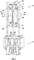
- FIG. 2 shows an embodiment of an assembly for a safety actuation device 40 affixed to the car frame 14 (typically on the sides of the elevator car 16).
- the safety actuation device 40 includes a mounting plate 41 with the electromagnetic actuators shown generally as 42a, 42b with magnetic brake pads shown generally as 44a, 44b affixed to the mounting plate 41 within a housing 50.
- a controller (not shown) is in electrical communication with each electromagnetic actuators 42a, 42b and is configured to control a supply/or elimination of electricity to the electromagnetic actuators 42a, 42b to cause their actuation.
- the controller employs various signals and inputs to determine whether or not to actuate the electromagnetic actuators 42a, 42b and thereby engage the safety brake 24.
- the elevator drive In operation, if the elevator car 16 reaches an over-speed condition, the elevator drive is commanded to stop and otherwise applies the brake to arrest movement of the drive sheave (not shown) and thereby arrest movement of elevator car 16.
- the safety actuation device 40 As described above, with the safety actuation device 40 described herein, if, however, the elevator car 16 continues to experience an over speed condition, the safety actuation device 40 then acts to trigger the safety brake 24 to engage guide rails 20 to arrest movement of elevator car 16.
- the controller receives various elevator parameters including the position or speed of the elevator car 16 as it moves in the hoistway. The controller actuates the safety actuation device 40 if the parameters satisfy a selected set of conditions. For example, the position or speed of the elevator car exceeds a selected threshold.
- the mounting plate 41 includes at least one aperture 45 disposed therein for mounting the safety actuation device 40 to the car frame 14.
- the apertures 45 on the mounting plate 41 and the fasteners 46 fixed on the car frame 14 allow a safety actuation device 40 to float horizontally (i.e., the mounting plate can slide front to back relative to the car frame 14 and elevator car 16 in the hoistway) when there is position variation between the elevator car 16 and the guide rail 20 (not shown, see FIG. 1 ).
- the safety actuation device 40 further includes a channel 56 extending substantially perpendicular from the mounting plate 41, and configured to surround the guide rail 20.
- the guide rail 20 is disposed within the channel 56.
- a first guide member 58a, 59a and a second guide member 58b, 59b may be positioned above and/or below the two housings 50a and 50b and positioned to each side of the channel 56.
- the guide rail 20 (not shown for clarity, see FIG. 1 ) is disposed within the channel 56 with the first guide member 58a, 59a and the second guide member 58b, 59b engaged with the guide rail 20 to minimize the impact of position variations between the safety actuation device 40 and the guide rail 20.
- guide members 58a, 58b, 59a, and 59b are depicted and further discussed as rollers, it should be appreciated that any configuration that can substantially align the channel 56 and thereby, the safety actuation device 40 with the guide rail 20 could be employed.
- slide guides, shoes, rollers, bearings, and the like slide guides, shoes, rollers, bearings, and the like.
- a mix of types of devices for the guide members 58a, 58b, 59a, 59b could be employed, for example slide guides in some applications with rollers in others.
- the present embodiments include a mounting assembly shown generally as 48 having at least one guide member, in this instance first guide member 58a, 59a and second guide member 58b, 59b disposed about channel 56, or alternatively at least one guide member 58a, 58b, 59a, 59b is affixed to the mounting plate 41 to substantially align the channel 56 of the safety actuation device 40 horizontally with respect to the guide rail 20 to improve the performance of safety actuation and reset due to the minimized position variations, (i.e., front to back) between the safety actuation device 40 and the guide rail 20.
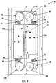
- FIG. 3 depicts a partial view of the safety actuation device 40 in accordance with an embodiment.
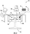
- FIG. 4 depicts a partially exploded cutaway view of the upper portion of safety actuation device 40 disposed with a guide rail 20 shown looking downward. In this view only the guide members 58a and 58b and associated components are visible. It should be understood that a similar set of components is employed on a lower portion of the safety actuation device 40 in association with guide members 59a and 59b.
- the safety actuation device 40 also includes one or more position encoders 60, 61 (second encoder 61 not shown as it is on the lower part of the safety actuation device 40 not seen in the view of FIG.
- the guide members 58a, 59a are rollers, rubber rings, wheels, or the like disposed in contact with and configured to maintain contact with the guide rail 20 as will be described further herein.
- the encoders 60, 61 are disposed on, and in, a fixed arrangement on the mounting plate 41 of the safety actuation device 40 and operably coupled with the guide member 58a, and 58b respectively.
- guide members 58b, and 59b are roller guides, slide guides, and the like.
- roller guides are employed.
- the position encoder(s) 60, 61 may be of any conventional configuration suitable for the application. In an embodiment rotary optical encoders are employed.
- any electromagnetic position transducer may be employed, such as synchros, resolvers, rotary variable differential transformers, hall-effect sensors and the like.
- the encoders 60, 61 are operably connected to the controller to facilitate the determination as needed to actuate the electromagnetic actuators 42a, 42b of the safety actuation device 40 as required.
- the safety actuation device 40 is also configured with a preload mechanism 62, 63 (63 also not shown) disposed on the mounting plate 41.
- the guide members 58b, 59b (also not shown in this view) and slidingly engaged, horizontally, with the preload mechanism 62, 63 and configured to maintain a force against the guide members 58b, 59b and to guiderail 20 respectively and thereby displacing the safety actuation device 40 (horizontally) to move within the apertures 45 on fasteners 46 to maintain reliable mating contact between the guide members 58a, 58b, and 59a, 59b with the guide rail 20 as the elevator car 16 (or the counterweight) moves.
- the guide members 58a and 59a i.e. with the mini-rotary encoder and roller
- the guide members 58a and 59a are forced to maintain contact with the guide rail 20 and thus rotate by relative motion (vertical in the hoistway) between the safety actuation device 40 and the guide rail 20 as the elevator car 16 moves. That is, the force provided by the preload mechanism 62, 63 (e.g., provided by spring 64, 65 (65 not depicted), or opposing magnet set 66, 67 (67 not shown), and the like, ensures reliable mating contact between the guide members 58a, 58b as well as 59a, 59b and the guide rail 20.
- the safety actuation device 40 is floating (at least horizontally) with respect to the car (counterweight) frame 14 via apertures 45 ( FIG. 3 ) on the mounting plate 41.
- the fasteners 46 ( FIG. 3 ) are fixed on the car frame 14 allow a safety actuation device 40 to float horizontally when there is position variation between the elevator car 16 and the guide rail 20.
- the tightly maintained contact between the guide members 58a, 58b as well as 59a, 59b, with the guide rail 20 ensures that the rotary encoders 60, 61 are reliably and accurately sensing the motion of the safety actuation device, and thereby the elevator car 16 as it travels through the hoistway.
- Another advantage to the speed detection mechanism of an embodiment is the improved flexibility for system integration over existing designs, also the system integration cost is independent of the building rise making it highly advantageous for high-rise or multicar ropeless applications.
Landscapes
- Engineering & Computer Science (AREA)
- Mechanical Engineering (AREA)
- Maintenance And Inspection Apparatuses For Elevators (AREA)
- Lift-Guide Devices, And Elevator Ropes And Cables (AREA)
Applications Claiming Priority (1)
| Application Number | Priority Date | Filing Date | Title |
|---|---|---|---|
| US15/377,450 US20180162693A1 (en) | 2016-12-13 | 2016-12-13 | Speed detection means for elevator or counterweight |
Publications (2)
| Publication Number | Publication Date |
|---|---|
| EP3360835A2 true EP3360835A2 (de) | 2018-08-15 |
| EP3360835A3 EP3360835A3 (de) | 2018-11-21 |
Family
ID=60673208
Family Applications (1)
| Application Number | Title | Priority Date | Filing Date |
|---|---|---|---|
| EP17206823.1A Withdrawn EP3360835A3 (de) | 2016-12-13 | 2017-12-12 | Geschwindigkeitserkennungsmittel für aufzug oder gegengewicht |
Country Status (3)
| Country | Link |
|---|---|
| US (1) | US20180162693A1 (de) |
| EP (1) | EP3360835A3 (de) |
| CN (1) | CN108217374A (de) |
Families Citing this family (15)
| Publication number | Priority date | Publication date | Assignee | Title |
|---|---|---|---|---|
| JP6807753B2 (ja) * | 2014-06-12 | 2021-01-06 | オーチス エレベータ カンパニーOtis Elevator Company | ブレーキ部材駆動機構 |
| US10494227B2 (en) * | 2014-06-12 | 2019-12-03 | Otis Elevator Company | Braking system resetting mechanism for a hoisted structure |
| US11485608B2 (en) * | 2016-03-18 | 2022-11-01 | Otis Elevator Company | Elevator safety system |
| US10112803B2 (en) * | 2016-04-01 | 2018-10-30 | Otis Elevator Company | Protection assembly for elevator braking assembly speed sensing device and method |
| US10494228B2 (en) * | 2017-02-28 | 2019-12-03 | Otis Elevator Company | Guiding devices for elevator systems having roller guides and motion sensors |
| EP3564171B1 (de) * | 2018-04-30 | 2021-04-14 | Otis Elevator Company | Vorrichtung zur betätigung der fangvorrichtung eines aufzugs |
| US11242222B2 (en) * | 2018-10-26 | 2022-02-08 | Otis Elevator Company | Elevator braking device mechanism |
| US11104545B2 (en) * | 2018-12-10 | 2021-08-31 | Otis Elevator Company | Elevator safety actuator systems |
| EP3677534B1 (de) * | 2019-01-02 | 2021-07-21 | Otis Elevator Company | Aktor einer sicherheitsvorrichtung eines aufzugs |
| CN109704168B (zh) * | 2019-02-26 | 2023-10-03 | 广州广日电梯工业有限公司 | 一种一体式电梯限速保护装置及具有该装置的电梯 |
| CN110422720A (zh) * | 2019-08-20 | 2019-11-08 | 武汉市云竹机电新技术开发有限公司 | 垂直提升全程超速保护系统 |
| CN112061927B (zh) * | 2020-09-28 | 2024-08-02 | 时空智能科技(宁波)有限公司 | 一种层门安全钳 |
| EP4273081A1 (de) * | 2022-05-05 | 2023-11-08 | Otis Elevator Company | Aufzugskabine mit elektronischem sicherheitsstellglied |
| CN119212942A (zh) * | 2022-05-26 | 2024-12-27 | 戴纳泰克动力与科技有限公司 | 用于电梯安全钳的紧凑型机电启动系统 |
| CN116553334B (zh) * | 2023-06-28 | 2026-02-24 | 日立电梯(中国)有限公司 | 一种提升轿厢平稳性且带速度检测功能的导靴 |
Family Cites Families (23)
| Publication number | Priority date | Publication date | Assignee | Title |
|---|---|---|---|---|
| US5931264A (en) * | 1997-09-25 | 1999-08-03 | Otis Elevator Company | Rail survey unit |
| US6196355B1 (en) * | 1999-03-26 | 2001-03-06 | Otis Elevator Company | Elevator rescue system |
| US6296080B1 (en) * | 2000-06-21 | 2001-10-02 | Otis Elevator Company | Variable traction mechanism for rotary actuated overspeed safety device |
| AU2003277477A1 (en) * | 2002-11-06 | 2004-06-07 | Lixin Sun | A detection method of lift guide rail perpendicularity and a detector for implementing this method |
| CN100542929C (zh) * | 2004-04-27 | 2009-09-23 | 三菱电机株式会社 | 电梯装置 |
| JP4722855B2 (ja) * | 2004-09-09 | 2011-07-13 | 三菱電機株式会社 | エレベータ装置 |
| EP2361869A4 (de) * | 2008-12-11 | 2014-05-14 | Mitsubishi Electric Corp | Aufzugsvorrichtung |
| JP5386377B2 (ja) * | 2010-01-05 | 2014-01-15 | 株式会社日立製作所 | エレベーター装置 |
| US8863908B2 (en) * | 2010-09-09 | 2014-10-21 | Inventio Ag | Controlling a drive motor of an elevator installation |
| RU2590799C2 (ru) * | 2011-10-07 | 2016-07-10 | Отис Элевэйтор Компани | Система торможения лифта |
| JP2013095526A (ja) * | 2011-10-28 | 2013-05-20 | Hitachi Ltd | エレベータ用速度検出装置 |
| WO2013115827A1 (en) * | 2012-02-03 | 2013-08-08 | Otis Elevator Company | System and method for reducing speed of an elevator car |
| CN104703905A (zh) * | 2012-10-04 | 2015-06-10 | 通力股份公司 | 用于电梯安装的导轨直线度测量系统 |
| US9688512B2 (en) * | 2012-11-15 | 2017-06-27 | Otis Elevator Company | Elevator brake |
| WO2014077811A1 (en) * | 2012-11-15 | 2014-05-22 | Otis Elevator Company | Brake |
| JP6008995B2 (ja) * | 2013-01-23 | 2016-10-19 | 三菱電機株式会社 | エレベータ装置 |
| US10654686B2 (en) * | 2015-06-30 | 2020-05-19 | Otis Elevator Company | Electromagnetic safety trigger |
| EP3141511B1 (de) * | 2015-09-08 | 2019-01-02 | Otis Elevator Company | Gehäuseanordnung für eine sicherheitsbetätigungsvorrichtung |
| US20170283216A1 (en) * | 2016-04-01 | 2017-10-05 | Otis Elevator Company | Condition sensing arrangement for elevator system brake assembly and method |
| US10112803B2 (en) * | 2016-04-01 | 2018-10-30 | Otis Elevator Company | Protection assembly for elevator braking assembly speed sensing device and method |
| US10252884B2 (en) * | 2016-04-05 | 2019-04-09 | Otis Elevator Company | Wirelessly powered elevator electronic safety device |
| US10315886B2 (en) * | 2016-04-11 | 2019-06-11 | Otis Elevator Company | Electronic safety actuation device with a power assembly, magnetic brake and electromagnetic component |
| US10889468B2 (en) * | 2016-12-13 | 2021-01-12 | Otis Elevator Company | Electronics safety actuator |
-
2016
- 2016-12-13 US US15/377,450 patent/US20180162693A1/en not_active Abandoned
-
2017
- 2017-12-12 EP EP17206823.1A patent/EP3360835A3/de not_active Withdrawn
- 2017-12-12 CN CN201711317263.5A patent/CN108217374A/zh not_active Withdrawn
Non-Patent Citations (1)
| Title |
|---|
| None |
Also Published As
| Publication number | Publication date |
|---|---|
| US20180162693A1 (en) | 2018-06-14 |
| CN108217374A (zh) | 2018-06-29 |
| EP3360835A3 (de) | 2018-11-21 |
Similar Documents
| Publication | Publication Date | Title |
|---|---|---|
| EP3360835A2 (de) | Geschwindigkeitserkennungsmittel für aufzug oder gegengewicht | |
| EP3342741B1 (de) | Elektronischer sicherheitsaufzug | |
| EP3447017B1 (de) | Synchronisierter elektronischer sicherheitsaktuator | |
| KR102616688B1 (ko) | 전자기식 안전 트리거 | |
| CN111620216B (zh) | 带有平移的安全设备块的电梯安全设备 | |
| CN111039124B (zh) | 电梯安全致动器系统 | |
| US12280984B2 (en) | Elevator system | |
| US11078045B2 (en) | Electronic safety actuator for lifting a safety wedge of an elevator | |
| US20080135346A1 (en) | Elevator arrangement | |
| CN109019229B (zh) | 电梯制动控制装置及电梯 | |
| EP3141511A1 (de) | Gehäuseanordnung für eine sicherheitsbetätigungsvorrichtung | |
| US20150251877A1 (en) | Elevator apparatus | |
| CN110451382B (zh) | 基于磁体组件到轨道的距离的同步 | |
| CN107265231B (zh) | 用于速度感测装置的保护装置 | |
| CN110790109B (zh) | 用于电梯系统的电子安全致动器组件 | |
| CN111285222B (zh) | 电梯安全促动器系统 | |
| WO2017023926A1 (en) | Device and method for actuating an elevator safety brake | |
| EP3377433B1 (de) | Gehäuseanordnung für eine sicherheitsbetätigungsvorrichtung | |
| WO2014136200A1 (ja) | エレベータ装置及びそのかご位置検出方法 | |
| JP7229358B2 (ja) | エレベータ装置 | |
| JP7216839B2 (ja) | エレベータ装置 | |
| CN110654954B (zh) | 电子安全致动器电磁导引 | |
| HK1111669A (en) | Elevator arrangement |
Legal Events
| Date | Code | Title | Description |
|---|---|---|---|
| PUAI | Public reference made under article 153(3) epc to a published international application that has entered the european phase |
Free format text: ORIGINAL CODE: 0009012 |
|
| STAA | Information on the status of an ep patent application or granted ep patent |
Free format text: STATUS: THE APPLICATION HAS BEEN PUBLISHED |
|
| AK | Designated contracting states |
Kind code of ref document: A2 Designated state(s): AL AT BE BG CH CY CZ DE DK EE ES FI FR GB GR HR HU IE IS IT LI LT LU LV MC MK MT NL NO PL PT RO RS SE SI SK SM TR |
|
| AX | Request for extension of the european patent |
Extension state: BA ME |
|
| PUAL | Search report despatched |
Free format text: ORIGINAL CODE: 0009013 |
|
| AK | Designated contracting states |
Kind code of ref document: A3 Designated state(s): AL AT BE BG CH CY CZ DE DK EE ES FI FR GB GR HR HU IE IS IT LI LT LU LV MC MK MT NL NO PL PT RO RS SE SI SK SM TR |
|
| AX | Request for extension of the european patent |
Extension state: BA ME |
|
| RIC1 | Information provided on ipc code assigned before grant |
Ipc: B66B 5/06 20060101AFI20181016BHEP Ipc: B66B 5/04 20060101ALI20181016BHEP Ipc: B66B 7/04 20060101ALI20181016BHEP |
|
| STAA | Information on the status of an ep patent application or granted ep patent |
Free format text: STATUS: REQUEST FOR EXAMINATION WAS MADE |
|
| 17P | Request for examination filed |
Effective date: 20190521 |
|
| RBV | Designated contracting states (corrected) |
Designated state(s): AL AT BE BG CH CY CZ DE DK EE ES FI FR GB GR HR HU IE IS IT LI LT LU LV MC MK MT NL NO PL PT RO RS SE SI SK SM TR |
|
| STAA | Information on the status of an ep patent application or granted ep patent |
Free format text: STATUS: THE APPLICATION IS DEEMED TO BE WITHDRAWN |
|
| 18D | Application deemed to be withdrawn |
Effective date: 20200701 |