EP3360987B1 - Abstandhalter für elektrolysegerät, und mit einem solchen abstandhalter ausgestattetes elektrolysegerät - Google Patents
Abstandhalter für elektrolysegerät, und mit einem solchen abstandhalter ausgestattetes elektrolysegerät Download PDFInfo
- Publication number
- EP3360987B1 EP3360987B1 EP18156083.0A EP18156083A EP3360987B1 EP 3360987 B1 EP3360987 B1 EP 3360987B1 EP 18156083 A EP18156083 A EP 18156083A EP 3360987 B1 EP3360987 B1 EP 3360987B1
- Authority
- EP
- European Patent Office
- Prior art keywords
- spacer
- cell
- thickness
- face
- internal
- Prior art date
- Legal status (The legal status is an assumption and is not a legal conclusion. Google has not performed a legal analysis and makes no representation as to the accuracy of the status listed.)
- Active
Links
Images


Classifications
-
- C—CHEMISTRY; METALLURGY
- C25—ELECTROLYTIC OR ELECTROPHORETIC PROCESSES; APPARATUS THEREFOR
- C25B—ELECTROLYTIC OR ELECTROPHORETIC PROCESSES FOR THE PRODUCTION OF COMPOUNDS OR NON-METALS; APPARATUS THEREFOR
- C25B13/00—Diaphragms; Spacing elements
- C25B13/02—Diaphragms; Spacing elements characterised by shape or form
-
- F—MECHANICAL ENGINEERING; LIGHTING; HEATING; WEAPONS; BLASTING
- F16—ENGINEERING ELEMENTS AND UNITS; GENERAL MEASURES FOR PRODUCING AND MAINTAINING EFFECTIVE FUNCTIONING OF MACHINES OR INSTALLATIONS; THERMAL INSULATION IN GENERAL
- F16J—PISTONS; CYLINDERS; SEALINGS
- F16J15/00—Sealings
- F16J15/02—Sealings between relatively-stationary surfaces
- F16J15/06—Sealings between relatively-stationary surfaces with solid packing compressed between sealing surfaces
- F16J15/08—Sealings between relatively-stationary surfaces with solid packing compressed between sealing surfaces with exclusively metal packing
- F16J15/0818—Flat gaskets
-
- C—CHEMISTRY; METALLURGY
- C25—ELECTROLYTIC OR ELECTROPHORETIC PROCESSES; APPARATUS THEREFOR
- C25B—ELECTROLYTIC OR ELECTROPHORETIC PROCESSES FOR THE PRODUCTION OF COMPOUNDS OR NON-METALS; APPARATUS THEREFOR
- C25B11/00—Electrodes; Manufacture thereof not otherwise provided for
- C25B11/02—Electrodes; Manufacture thereof not otherwise provided for characterised by shape or form
-
- C—CHEMISTRY; METALLURGY
- C25—ELECTROLYTIC OR ELECTROPHORETIC PROCESSES; APPARATUS THEREFOR
- C25B—ELECTROLYTIC OR ELECTROPHORETIC PROCESSES FOR THE PRODUCTION OF COMPOUNDS OR NON-METALS; APPARATUS THEREFOR
- C25B13/00—Diaphragms; Spacing elements
- C25B13/04—Diaphragms; Spacing elements characterised by the material
-
- C—CHEMISTRY; METALLURGY
- C25—ELECTROLYTIC OR ELECTROPHORETIC PROCESSES; APPARATUS THEREFOR
- C25B—ELECTROLYTIC OR ELECTROPHORETIC PROCESSES FOR THE PRODUCTION OF COMPOUNDS OR NON-METALS; APPARATUS THEREFOR
- C25B9/00—Cells or assemblies of cells; Constructional parts of cells; Assemblies of constructional parts, e.g. electrode-diaphragm assemblies; Process-related cell features
- C25B9/70—Assemblies comprising two or more cells
- C25B9/73—Assemblies comprising two or more cells of the filter-press type
-
- C—CHEMISTRY; METALLURGY
- C25—ELECTROLYTIC OR ELECTROPHORETIC PROCESSES; APPARATUS THEREFOR
- C25B—ELECTROLYTIC OR ELECTROPHORETIC PROCESSES FOR THE PRODUCTION OF COMPOUNDS OR NON-METALS; APPARATUS THEREFOR
- C25B9/00—Cells or assemblies of cells; Constructional parts of cells; Assemblies of constructional parts, e.g. electrode-diaphragm assemblies; Process-related cell features
- C25B9/70—Assemblies comprising two or more cells
- C25B9/73—Assemblies comprising two or more cells of the filter-press type
- C25B9/75—Assemblies comprising two or more cells of the filter-press type having bipolar electrodes
-
- C—CHEMISTRY; METALLURGY
- C25—ELECTROLYTIC OR ELECTROPHORETIC PROCESSES; APPARATUS THEREFOR
- C25B—ELECTROLYTIC OR ELECTROPHORETIC PROCESSES FOR THE PRODUCTION OF COMPOUNDS OR NON-METALS; APPARATUS THEREFOR
- C25B9/00—Cells or assemblies of cells; Constructional parts of cells; Assemblies of constructional parts, e.g. electrode-diaphragm assemblies; Process-related cell features
- C25B9/70—Assemblies comprising two or more cells
- C25B9/73—Assemblies comprising two or more cells of the filter-press type
- C25B9/77—Assemblies comprising two or more cells of the filter-press type having diaphragms
-
- F—MECHANICAL ENGINEERING; LIGHTING; HEATING; WEAPONS; BLASTING
- F16—ENGINEERING ELEMENTS AND UNITS; GENERAL MEASURES FOR PRODUCING AND MAINTAINING EFFECTIVE FUNCTIONING OF MACHINES OR INSTALLATIONS; THERMAL INSULATION IN GENERAL
- F16J—PISTONS; CYLINDERS; SEALINGS
- F16J15/00—Sealings
- F16J15/02—Sealings between relatively-stationary surfaces
- F16J15/06—Sealings between relatively-stationary surfaces with solid packing compressed between sealing surfaces
- F16J15/10—Sealings between relatively-stationary surfaces with solid packing compressed between sealing surfaces with non-metallic packing
- F16J15/12—Sealings between relatively-stationary surfaces with solid packing compressed between sealing surfaces with non-metallic packing with metal reinforcement or covering
- F16J15/121—Sealings between relatively-stationary surfaces with solid packing compressed between sealing surfaces with non-metallic packing with metal reinforcement or covering with metal reinforcement
- F16J15/122—Sealings between relatively-stationary surfaces with solid packing compressed between sealing surfaces with non-metallic packing with metal reinforcement or covering with metal reinforcement generally parallel to the surfaces
-
- F—MECHANICAL ENGINEERING; LIGHTING; HEATING; WEAPONS; BLASTING
- F16—ENGINEERING ELEMENTS AND UNITS; GENERAL MEASURES FOR PRODUCING AND MAINTAINING EFFECTIVE FUNCTIONING OF MACHINES OR INSTALLATIONS; THERMAL INSULATION IN GENERAL
- F16J—PISTONS; CYLINDERS; SEALINGS
- F16J15/00—Sealings
- F16J15/02—Sealings between relatively-stationary surfaces
- F16J15/06—Sealings between relatively-stationary surfaces with solid packing compressed between sealing surfaces
- F16J15/10—Sealings between relatively-stationary surfaces with solid packing compressed between sealing surfaces with non-metallic packing
- F16J15/12—Sealings between relatively-stationary surfaces with solid packing compressed between sealing surfaces with non-metallic packing with metal reinforcement or covering
- F16J15/121—Sealings between relatively-stationary surfaces with solid packing compressed between sealing surfaces with non-metallic packing with metal reinforcement or covering with metal reinforcement
- F16J15/125—Sealings between relatively-stationary surfaces with solid packing compressed between sealing surfaces with non-metallic packing with metal reinforcement or covering with metal reinforcement generally perpendicular to the surfaces
-
- F—MECHANICAL ENGINEERING; LIGHTING; HEATING; WEAPONS; BLASTING
- F16—ENGINEERING ELEMENTS AND UNITS; GENERAL MEASURES FOR PRODUCING AND MAINTAINING EFFECTIVE FUNCTIONING OF MACHINES OR INSTALLATIONS; THERMAL INSULATION IN GENERAL
- F16J—PISTONS; CYLINDERS; SEALINGS
- F16J15/00—Sealings
- F16J15/02—Sealings between relatively-stationary surfaces
- F16J15/06—Sealings between relatively-stationary surfaces with solid packing compressed between sealing surfaces
- F16J15/10—Sealings between relatively-stationary surfaces with solid packing compressed between sealing surfaces with non-metallic packing
- F16J15/12—Sealings between relatively-stationary surfaces with solid packing compressed between sealing surfaces with non-metallic packing with metal reinforcement or covering
- F16J15/121—Sealings between relatively-stationary surfaces with solid packing compressed between sealing surfaces with non-metallic packing with metal reinforcement or covering with metal reinforcement
- F16J15/127—Sealings between relatively-stationary surfaces with solid packing compressed between sealing surfaces with non-metallic packing with metal reinforcement or covering with metal reinforcement the reinforcement being a compression stopper
-
- C—CHEMISTRY; METALLURGY
- C25—ELECTROLYTIC OR ELECTROPHORETIC PROCESSES; APPARATUS THEREFOR
- C25B—ELECTROLYTIC OR ELECTROPHORETIC PROCESSES FOR THE PRODUCTION OF COMPOUNDS OR NON-METALS; APPARATUS THEREFOR
- C25B1/00—Electrolytic production of inorganic compounds or non-metals
- C25B1/01—Products
- C25B1/02—Hydrogen or oxygen
- C25B1/04—Hydrogen or oxygen by electrolysis of water
-
- F—MECHANICAL ENGINEERING; LIGHTING; HEATING; WEAPONS; BLASTING
- F16—ENGINEERING ELEMENTS AND UNITS; GENERAL MEASURES FOR PRODUCING AND MAINTAINING EFFECTIVE FUNCTIONING OF MACHINES OR INSTALLATIONS; THERMAL INSULATION IN GENERAL
- F16J—PISTONS; CYLINDERS; SEALINGS
- F16J15/00—Sealings
- F16J15/02—Sealings between relatively-stationary surfaces
- F16J15/06—Sealings between relatively-stationary surfaces with solid packing compressed between sealing surfaces
- F16J15/08—Sealings between relatively-stationary surfaces with solid packing compressed between sealing surfaces with exclusively metal packing
- F16J15/0818—Flat gaskets
- F16J2015/085—Flat gaskets without fold over
-
- F—MECHANICAL ENGINEERING; LIGHTING; HEATING; WEAPONS; BLASTING
- F16—ENGINEERING ELEMENTS AND UNITS; GENERAL MEASURES FOR PRODUCING AND MAINTAINING EFFECTIVE FUNCTIONING OF MACHINES OR INSTALLATIONS; THERMAL INSULATION IN GENERAL
- F16J—PISTONS; CYLINDERS; SEALINGS
- F16J15/00—Sealings
- F16J15/02—Sealings between relatively-stationary surfaces
- F16J15/06—Sealings between relatively-stationary surfaces with solid packing compressed between sealing surfaces
- F16J15/08—Sealings between relatively-stationary surfaces with solid packing compressed between sealing surfaces with exclusively metal packing
- F16J15/0818—Flat gaskets
- F16J2015/0856—Flat gaskets with a non-metallic coating or strip
-
- Y—GENERAL TAGGING OF NEW TECHNOLOGICAL DEVELOPMENTS; GENERAL TAGGING OF CROSS-SECTIONAL TECHNOLOGIES SPANNING OVER SEVERAL SECTIONS OF THE IPC; TECHNICAL SUBJECTS COVERED BY FORMER USPC CROSS-REFERENCE ART COLLECTIONS [XRACs] AND DIGESTS
- Y02—TECHNOLOGIES OR APPLICATIONS FOR MITIGATION OR ADAPTATION AGAINST CLIMATE CHANGE
- Y02E—REDUCTION OF GREENHOUSE GAS [GHG] EMISSIONS, RELATED TO ENERGY GENERATION, TRANSMISSION OR DISTRIBUTION
- Y02E60/00—Enabling technologies; Technologies with a potential or indirect contribution to GHG emissions mitigation
- Y02E60/30—Hydrogen technology
- Y02E60/36—Hydrogen production from non-carbon containing sources, e.g. by water electrolysis
Definitions
- the invention relates to an electrolysis cell and a spacer for such a cell.
- Electrodes To produce hydrogen industrially in a decentralized and ecological way, the electrolysis of water is preferred to reforming.
- Current electrolyser devices comprise a plurality of electrochemical cells, supplied with water, and each comprising a pair of electrodes.
- the cells are generally flat and grouped in one or more stacks, or "stack" in English, so that two superimposed cells each have a common electrode.
- the Applicant has proposed seals which make it possible to stack a large number of cells, for example up to 300 cells.
- the cells are capable of withstanding large clamping forces and internal pressures of around 45 bar.
- Such seals are satisfactory and are for example described in WO 2015/004378 .
- the invention improves the situation.
- the Applicant proposes a spacer according to claim 1, for an electrolyser cell, of substantially annular shape and comprising: a peripheral part having two main faces parallel and opposite to each other, the distance separating the two faces main defining a thickness of the spacer, and an internal part having a thickness strictly less than the thickness of the spacer, the peripheral part and the internal part being in one piece and connected to each other in forming an internal annular shoulder so that the internal part has a substantially annular intermediate face and extending along a plane parallel to the two main faces of the peripheral part and located between the two main faces.
- the Applicant proposes an electrolysis cell comprising two electrodes which are substantially flat and parallel to one another, a membrane and a substantially annular part forming a spacer between the two electrodes in a direction. stack, the two electrodes and the spacer together delimiting an internal space of the cell.
- the spacer comprises a peripheral part having two main faces opposite one relative to the other and in respective abutment against one and the other of the two electrodes, the distance separating the two main faces defining a thickness of the part.
- peripheral corresponding to the thickness of the internal space of the cell in the stacking direction, and an internal part having a thickness strictly less than the thickness of the peripheral part, the peripheral part and the internal part being of a in one piece and connected to each other by forming an internal annular shoulder so that the internal part has a substantially annular intermediate face opposite and at a distance from one of the two electrodes, the intermediate face supporting the membrane so that the membrane divides the internal space of the cell into two compartments.
- anode In the following, the terms “anode”, “cathode” and their derivatives are used in accordance with what is shown in the figures. However, the proposed electrolyser structures can operate in reverse with respect to what is shown. For example, by reversing the polarization and swapping the input assignments and out of fluid, the anode compartment can become the cathode compartment and vice versa. Unless otherwise stated, the example dimensions given below are nominal values in the idle state of the parts.
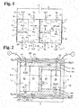
- FIG. 1 illustrates the electrochemical aspect of an electrolyser battery.
- An electrolyser cell 1 comprises a plurality of water electrolysis cells 3 stacked on top of each other in a stacking direction XX. Only two cells 3 are represented in figure 1 .
- Each cell 3 comprises a pair of electrodes 5, 7, a proton exchange membrane 9, or PEM membrane for "proton exchange membrane” in English, and an external wall 10.
- the two electrodes 5, 7 are each formed of a bipolar plate 4.
- a bipolar plate 4 comprises two faces opposite one with respect to the other. A first face forms an anode 5 of a first cell 3, while a second face forms a cathode 7 of a second cell 3 adjacent to the first cell 3. With the exception of the ends of cell 1, each plate bipolar 4 is arranged at the interface of two adjacent cells 3.
- the two bipolar plates 4 forming the electrodes 5, 7 of a cell 3 are of substantially planar shape.
- the electrodes 5, 7 are installed substantially parallel to one another and perpendicular to the stacking direction XX.
- the two electrodes 5, 7 are here of identical structures and compositions.
- the bipolar plates 4 can be adapted as a function of their function. For example, coatings can be provided to chemically protect the electrodes 5, 7 from the contents of the anode and cathode compartments.
- the PEM membrane 9 is disposed between the two electrodes 5, 7 and substantially parallel to the electrodes 5, 7.
- the space between the anode 5 and the PEM membrane 9 defines an anode compartment 11.
- the space between the cathode 7 and the PEM membrane 9 defines a cathode compartment 13.
- the anode compartment 11 and the cathode compartment 13 each contain 1 'water.
- deionized water is used.
- water has a conductivity of less than 1 ⁇ S.cm -2 .
- the external wall 10 extends substantially in the stacking direction XX and delimits the anode compartment 11 and the cathode compartment 13.
- a first water inlet 51 is formed through the external wall 10 so as to open into the anode compartment 11.
- a second water inlet 53 is formed through the outer wall 10 so as to open into the cathode compartment 13.
- An outlet 55 of the anode compartment 11 is formed through the outer wall 10.
- the outlet 55 of the anode compartment 11 takes the form of a passage suitable for discharging water loaded with oxygen (O 2 ) in gaseous form.
- An outlet 57 of the cathode compartment 13 is formed through the external wall 10.
- the outlet 57 of the cathode compartment 13 takes the form of a passage suitable for discharging water loaded with dihydrogen (H2) in gaseous form.
- the reactions (1) and (2) within the electrolysis cell 1 are controlled by adjusting the direct current or the voltage applied to the electrodes 5, 7.
- the anode 5 and the cathode 7 at the respective ends of the electrolysis cell 1 are intended to be connected to a direct current generator.
- the electrical connections and the current source common to cells 3 of battery 1 are not shown.
- the first water inlet 51, the second water inlet 53, the outlet 55 for oxygen (O 2 ) and the outlet 57 for dihydrogen (H2) from each cell 3 of the stack 1 can be fluidly connected to the inputs / outputs counterparts of the other cells 3 of the stack 1.
- the first water inlets 51 of the stack 1 are supplied by a common source of water
- the second water inlets 53 of the stack 1 are supplied by a source d 'common water
- the dioxygen (O 2 ) outlets of cell 1 are connected to a common collector
- the dihydrogen (H2) outlets of cell 1 are connected to a common collector.
- the second water inlets 53 improve the thermal regulation and limit the drying out of the PEM membrane 9. As a variant, the second water inlets 53 are omitted from the cathode 7 side.
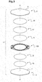
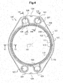
- the cell 3 comprises the two bipolar plates 4, one forming an anode 5 while the other forms cathode 7, a piece forming a spacer 100, the PEM membrane 9, two current diffusers 15, hereinafter diffusers 15, and two porous current collectors 17, hereinafter collectors 17.
- the spacer 100 is held between the anode 5 and the cathode 7 in the stacking direction XX.
- the anode 5, the cathode 7 and the spacer 100 together delimit an internal space of the cell 3, inside the spacer 100.
- the PEM membrane 9 is arranged in the internal space of the cell 3 so delimiting the anode 11 and cathode 13 compartments.
- Each of the two compartments 11, 13 is occupied respectively by a diffuser 15 and a collector 17.
- Each anode compartment 11 and cathode compartment 13 houses a diffuser 15 on the side of the anode 5, respectively the cathode 7, and a collector 17 on the side of the PEM membrane 9.
- the PEM membrane 9 is placed, or sandwiched, between the two collectors 17.
- the spacer 100 is of substantially annular shape so as to separate the internal space from the outside of the cell 3.
- the spacer 100 here forms the external wall 10 of the cell 3.
- the spacer 100 also forms an insulator between the anode 5, the cathode 7 and the PEM membrane 9.
- the anode compartment 11 and the cathode behavior 13, respectively the two diffusers 15, and respectively the two collectors 17, are similar in pairs but of different dimensions.
- the two bipolar plates 4 are identical.
- the homologous parts on either side of the PEM membrane 9 present, in addition to their dimensions, minor differences.
- the anode face 5 of the first bipolar plate 4 and the cathode face 7 of the second bipolar plate 4 are respectively supported on either side of the spacer 100 according to the stacking direction XX.
- the spacer 100 maintains the distance between the two bipolar plates 4 in the stacking direction XX.
- the PEM membrane 9 is in abutment against the spacer 100 on the cathode side and in abutment against the stack of the collector 17, the diffuser 15 and the anode 5 on the anode side.
- the stacking direction XX also corresponds to a clamping direction and a thickness direction of the bipolar plates 4, of the spacer 100, of the PEM membrane 9, of the diffusers 15 and of the collectors 17.
- the dimensions of the PEM membrane 9, the diffusers 15 and the collectors 17 are adjusted so as to substantially fill the cell 3.
- the tightening of the spacer 100 between the anode 5 and the cathode 7 seals the cell 3 and the electrical contacts between the diffusers 15, the collectors 17 and the bipolar plates 4.
- the anode compartment 11 and the cathode compartment 13 are fluidly isolated from the outside of the cell 3.
- the first water inlet 51, the second water inlet 53, the outlet 55 for oxygen (O 2 ) and the outlet 57 for dihydrogen (H2) from cell 3 are respectively connected to a first water supply channel 151, a second water supply channel 153, a dioxygen (O 2 ) evacuation channel 155 and a dihydrogen (H2) evacuation channel 157 common to the other cells 3 of cell 1 not shown in figure 2 .
- the PEM membrane 9 has a disc shape. Its diameter here is around 298 millimeters. Its thickness is between approximately 0.05 and 0.3 millimeter.
- the bipolar plates 4 take the form of generally circular flat plates.
- the bipolar plates 4 each have an outer edge corresponding to the shape of the spacer 100.
- the outer edge of the anode 5 and / or the outer edge of the cathode 7 have a connector for connection to the source of current.
- the anode 5 and the cathode 7 are made of an electrically conductive material, for example titanium.
- the diffusers 15 are electrically conductive.
- the diffusers 15 include passages for the fluids in one or more directions substantially perpendicular to the thickness direction, that is to say perpendicular to the stacking direction XX in the assembled state.
- the diffusers 15 take the form of disc-shaped grids.
- the diffusers 15 can take other forms suitable for homogenizing the circulation of fluids in the anode compartments 11 and cathode 13.
- the diameter here is approximately 280 millimeters in the anode compartment 11 while it is approximately 265 millimeters in the cathode compartment 13.
- the thickness is between approximately 0.9 and 1.2 millimeters .
- the diffusers 15 are made of an electrically conductive material, for example based on titanium.
- the diffusers 15 here take the form of grids whose mesh is arranged so that a circulation of fluid in the direction of the main plane of the diffuser 15 is as homogeneous as possible by extending in the directions of the plane. For example, the meshes form a diamond of 4.5 by 2.7 millimeters.
- the diffusers 15 can be produced by means of a set of channels formed in the anode 5 on the one hand and in the cathode 7 on the other hand.
- the diffuser 15 is omitted from the side of the cathode 7.
- This variant is preferred when the second water inlets 53 are omitted and the circulation of water in the cathode compartment 13 is not provided.
- the dimensions can be adapted. For example, the thicknesses on the cathode side can be reduced.
- the collectors 17 are electrically conductive.
- the collectors 17 are finely porous so that the exchanges of liquid and gaseous fluids are allowed through the collectors 17 in one or more directions substantially parallel to their thickness direction, that is to say parallel to the direction of stack XX in the assembled state.
- the collectors 17 have a disc shape. Their diameter here is around 280 millimeters in the anode compartment 11 while it is around 265 millimeters in the cathode compartment 13. The thickness is between 1.3 and 1.8 millimeters. Alternatively, in particular in the absence of water circulation in the cathode compartment 13, the thicknesses may be less on the cathode side.
- the collectors 17 are made of an electrically conductive material which is permeable to liquids, for example sintered and porous titanium.
- the external shapes and dimensions of the diffusers 15 and of the collectors 17 correspond to the internal shapes and dimensions of the spacer 100 inside which the diffusers 15 and the collectors 17 are housed.
- a mounting clearance is provided to allow expansion of the diffusers 15, the collectors 17 and the spacer 100 in operation.
- the diameter of the PEM membrane 9 is less than the interior diameter of the spacer 100 on the anode side and greater than the interior diameter of the spacer 100 on the cathode side.
- the bipolar plates 4 have shapes and dimensions adapted to bear against the spacer 100.
- the anode 5, the cathode 7, the two diffusers 15 and the two collectors 17 of the cell 3 are in general disc shape.
- the spacer 100 has a corresponding generally circular outline.
- the substantially axisymmetric shapes facilitate the resistance to pressure as well as a homogeneous distribution of the fluids in the cells 3.
- the circular shapes remain optional.
- the spacer 100 can have a substantially annular shape, that is to say a closed contour hollowed out at its center, while having non-circular internal and external edges viewed in the stacking direction XX, by for example rectangular, square or any other suitable closed shape.
- the anode 5, the cathode 7, the two diffusers 15 and the two collectors 17 of the cell 3 may have shapes corresponding to that of the spacer 100 and not circular.
- the dimensions given above by way of example can be adapted according to the desired applications.
- the PEM 9 membrane is replaced by an anionic membrane.
- the electrolyte is basic instead of being acidic.
- the hydroxide anions (HO - ) cross the anionic membrane.
- the chemical reactions in the compartments are modified, but the structure and operation of cell 1 remain similar.
- the figures 4 to 9 show an embodiment of a spacer 100, which can be used in cells 3 and a stack 1 as described so far.
- the spacer 100 is in one piece and of substantially annular shape.
- the spacer 100 has a substantially flat crown shape: it extends along a main plane, corresponding to the plane of the figures 4 and 5 , and has a thickness direction perpendicular to the main plane.
- the thickness direction of the spacer 100 is parallel to the stacking direction XX.
- the sections of the spacer 100 have, over the entire circumference of the spacer 100, a width substantially greater than its thickness.
- the spacer 100 comprises a peripheral part 101 and an internal part 103.
- the internal part 103 projects from the peripheral part 101 towards the inside of the substantially annular shape.
- the peripheral part 101 has a first main face 105 and a second main face 107 opposite one another and extending perpendicular to the thickness direction of the spacer 100.
- the internal part 103 having a bearing face 109.
- the bearing face 109 is, here, substantially planar, annular and coplanar with the second main face 107.
- the bearing face 109 of the internal part 103 is substantially in the extension of the second face main 107 of the peripheral part 101.
- the internal part 103 has an intermediate face 111 opposite the bearing face 109.
- the intermediate face 111 is, here, substantially planar, annular and set back with respect to the first main face 105 of the peripheral part 101 in the thickness direction.
- the intermediate face 111 extends along a plane parallel to the first main face 105 and to the second main face 107 and between the two main faces 105, 107 of the peripheral part 101. In the assembled state, the intermediate face 111 defines the position of the border between the anode compartment 11 and the cathode compartment 13 and receives the PEM membrane 9.
- peripheral part 101 and the internal part 103 are formed in one piece and connected to each other by forming an internal annular shoulder.
- the peripheral part 101 has a thickness 200.
- the thickness 200 is defined by the distance separating the two main faces 105, 107 from the peripheral part 101.
- the thickness 200 corresponds substantially to the overall thickness of the spacer 100
- the internal part 103 has a thickness 201 defined by the distance separating the bearing face 109 and the intermediate face 111.
- the thickness 201 of the internal part 103 is strictly less than the thickness 200 of the peripheral part 101.
- L thickness 201 corresponds substantially to the thickness of the cathode compartment 13.
- the difference between the thickness 200 of the peripheral part 101 and the thickness 201 of the internal part 103 corresponds substantially to the thickness of the anode compartment 11, at thickness of the PEM 9 membrane.
- connection surface 113 is annular and substantially cylindrical.
- the height of the connection surface 113 corresponds to the difference between the thickness 200 of the peripheral part 101 and the thickness 201 of the internal part 103.
- the connection surface 113 forms an anodic part of the external wall 10 of the cell 3 in the assembled state. In this state, the connection surface 113 delimits the outline of the anode compartment 11 of the cell 3.
- the spacer 100 also has an outer edge 115 and an inner edge 117.
- the outer edge 115 connects the first main face 105 and the second main face 107 of the peripheral part 101 to each other.
- the outer edge 115 forms the outer contour of the annular shape of the spacer 100.
- the height of the outer edge 115 corresponds to the thickness 200 of the peripheral part 101.
- the inner edge 117 connects the bearing face 109 and the intermediate face 111 of the internal part 103 to each other.
- the internal edge 117 extends over the internal contour of the annular shape of the spacer 100.
- the height of the internal edge 117 corresponds to the thickness 201 of the internal part 103.
- the internal edge 117 has a diameter of about 265 millimeters.
- the internal edge 117 forms a cathodic part of the external wall 10 of the cell 3 in the assembled state. In this state, the internal edge 117 delimits the outline of the cathode compartment 13 of the cell 3.
- the spacer 100 has a first orifice 121, a second orifice 123, a third orifice 125 and a fourth orifice 127.
- the four orifices 121, 123, 125, 127 are through in the thickness direction.
- the first port 121 and the second port 123 are substantially diametrically opposed to each other in the annular shape of the spacer 100.
- the third port 125 and the fourth port 127 are substantially diametrically opposed to each other to the other in the annular shape of the spacer 100.
- the four orifices 121, 123, 125, 127 each have a closed contour, here circular.
- the four orifices 121, 123, 125, 127 allow the circulation of a fluid in the thickness direction through the spacer 100.
- the four orifices 121, 123, 125, 127 respectively form portions of the first water supply channel 151, the second water supply channel 153, the oxygen (O 2 ) exhaust channel 155 and the dihydrogen exhaust channel ( H2) 157 of stack 1.
- the spacer 100 includes a passage 131, respectively 133, 135, 137.
- the passage 131, respectively 133, 135 and 137 extends between the orifice 121, respectively 123, 125 and 127, and the internal space of the spacer 100, here substantially in a radial direction.
- the fluids pass between the channel 151, respectively 153, 155 and 157, and the interior space of the cell 3 via the passage 131, respectively 133, 135 and 137.
- the passage 131 forms the first water inlet 51 in the anode compartment 11, respectively the second water inlet 53 in the cathode compartment 13, respectively the outlet 55 of oxygen (O 2 ) from the anode compartment 11, respectively the outlet 57 of dihydrogen (H2) from the cathode compartment 13.
- the passage 131 leads to the diffuser 15.
- the passages 131, 133, 135, 137 take the form of grooves formed in one of the two main faces 105, 107, for example produced by shrinking material.
- the passages 131 and 135 are formed on the anode side, that is to say in the first main face 105 in the example of the figures 4 and 5
- the passages 133 and 137 are provided on the cathode side, that is in the second main face 107 in the example of figures 4 and 5 .
- the edges of the passages 131 and 135 on the anode side are flared. This improves the homogeneity of the fluid circulation in the anode compartment 11.
- the edges of the passages 133, 137 on the cathode side are straight. Alternatively, the edges on the anode side are straight and / or the edges on the cathode side are flared.
- the four orifices 121, 123, 125, 127 and their passage 131, 133, 135, 137 respectively are grouped two by two in the circumference of the spacer 100.
- the channels 151, 153, 155 , 157 for fluids in an assembled state of the spacer 100 are thus in close proximity two by two, which reduces the size of the stack 1.
- the inputs 51 and 53 can be arranged at the bottom while the outputs 55 and 57 can be arranged at the top.
- the evacuation of gases by exits 55 and 57 is facilitated by the effect of Archimedes' thrust.
- This arrangement remains optional: the orifices can be distributed differently in the spacer 100.
- the communication portions are enlarged compared to the current portions.
- the outer edge 115 takes the form of two arcs of circle of approximately 400 millimeters in diameter.
- the outer edge 115 takes the form of two arcs of a circle of approximately 320 millimeters in diameter.
- the communication and current portions are connected to each other in a substantially continuous manner.
- the outer edge 115 has a notch 129 on each of the two communication portions.
- the notches 129 have, here, a semicircle shape and are arranged so as to cooperate with a guide of a stack 1.
- the notches 129 facilitate the indexing of the spacers 100 during assembly of the stack 1 and improve their maintained by an external structure. Alternatively, other guiding and fixing means are provided.
- the spacer 100 includes a core and an envelope at least partially covering the core.
- the core is made from metal, for example stainless steel.
- the envelope has, here, a composition based on ethylene-propylene-diene monomer (EPDM).
- EPDM ethylene-propylene-diene monomer
- the composition of the envelope has a higher elasticity than that of the composition of the core.
- the EPDM used here makes it possible to obtain mechanical properties, and in particular a resistance to extreme temperatures, improved compared to other elastomers.
- the use of EPDM rather than other elastomers remains optional.
- fluoropolymers (FKM), silicones (VMQ), ethylene vinyl acetate (EVA and EVM) and chlorinated polyethylenes (CM) can be used depending on the desired applications.
- FKM fluoropolymers
- VMQ silicones
- EVA and EVM ethylene vinyl acetate
- CM chlorinated polyethylenes
- the envelope is adhered to the core.
- the spacer 100 is obtained by injection of the material constituting the envelope in contact with the
- the envelope is present at least on each of the surfaces of the core which must be electrically isolated during operation.
- the electrically insulating casing covers the core at least on the areas of the spacer 100 in contact with the internal space of the cell 3 in the assembled state. Chemical degradation of the core by the fluids of cell 3 is limited.
- the envelope covers the core, continuously, and on all surfaces except the outer edge 115 and areas of the first main surface 105 and the second main face 107 located along the outer edge 115 and notches 129.
- the uncoated surfaces of the core make it possible to facilitate the manufacture of the spacer 100, to save material and to guide and align the parts with precision when mounting the stack 1.
- the cell 3 further comprises seals arranged so as to prevent leakage of fluids between the parts forming the cell 3.
- the seals, or sealing lines are formed by ribs, or local thicknesses, formed in the envelope 163.
- the spacer 100 in one piece, provides both a function structural by delimiting the compartments 11, 13 of the cell 3, an electrical insulation function and a sealing function.
- the addition of additional sealing parts is superfluous.
- at least some of the seals are formed by parts distinct from the spacer 100. For example, deformable parts based on an elastomer of the rod or rod type are placed between parts which are substantially non-deformable.
- at least some of the ribs shown in the figures can be replaced by seals which are not integral with the spacer 100.
- the anode sealing line 205 is arranged between the first main face 105 and the anode 5 in the stacking direction XX while ensuring the sealing of the anode compartment 11 relative to outside. Fluid communication is preserved substantially in a radial direction between the anode compartment 11 and the orifice 121, respectively the orifice 125, via the passage 131, respectively the passage 135.
- the cathodic sealing line 207 is disposed between the second main face 107 and the cathode 7 in the stacking direction XX while ensuring the sealing of the cathode compartment 13 relative to the outside.
- Fluid communication is preserved substantially in a radial direction between the cathode compartment 13 and the orifice 123, respectively the orifice 127, via the passage 133, respectively the passage 137.
- the intermediate sealing line 209 is disposed between the intermediate face 111 and the PEM membrane 9 in the stacking direction XX while ensuring the fluid tightness of the anode compartment 11 and of the cathode compartment 13 relative to one another.
- the orifice contour sealing lines 223 and 227 are arranged between the first main face 105 and the anode 5 while the orifice contour sealing lines 221 and 225 are arranged between the second main face 107 and the cathode 7.
- the anodic sealing line 205 merges locally with the sealing lines around the orifice outline 223 and 227 while the cathodic sealing line 207 merges locally with the orifice contour sealing lines 221 and 225.
- each rib formed in the envelope is housed in part in a corresponding groove made in the core.
- each of the ribs has a section of substantially symmetrical shape, here semi-circular.
- other forms of section are implemented.
- the grooves may, for example, have a rounded section.
- the ribs may have sections that are substantially square, rectangular, trapezoidal, or even pointed or clipped, or even asymmetrical.
- the ribs protrude from the first main face 105, respectively from the second main face 107, from the bearing face 109 and from the intermediate face 111.
- the ribs are compressed in the stacking direction XX and have an expansion substantially in the directions perpendicular to the stacking direction XX, here in the grooves formed in the core.
- the ribs are applied against the facing parts and thus ensure the seals.
- the presence of the grooves is combined with seals separate from the spacer 100. The grooves reduce the risk that the sealing lines are improperly positioned or damaged.
- the height of a rib is reduced from 10% to 40% relative to the height at rest of this same rib.
- the dimensions of the grooves are selected so that the portion of the volume of the grooves formed in the core occupied by the material of the ribs is less than 90%.
- the envelope has a substantially uniform thickness around the core with the exception of the ribs which form local excess thicknesses of the envelope.
- the thickness of the envelope outside of the exception zones is greater than 0.3 millimeter.
- the part of the envelope covering the core on the internal edge 117 also constitutes an exception to the uniformity of the thickness.
- the part of the envelope covering the internal edge 117 thus has a thickness greater than that of the envelope in the other zones of the spacer 100. This difference in thickness results from the injection molding operation of the envelope . As a variant, this extra thickness is omitted.
- the anode compartment 11 and the cathode compartment 13 may be subjected to different operating pressures.
- the anode compartment 11 operates at a static pressure substantially lower than that of the cathode compartment 13.
- the pressure difference participates in a uniform tightening of the PEM membrane 9 against the collector 17 disposed in the anode compartment 11.
- the PEM membrane 9 is kept flat and substantially homogeneous over its entire surface against the anode collector 17.
- the tightness is reinforced.
- the PEM 9 membrane has little or no stress in tension. The risks of deformation by traction and / or PEM 9 membrane shear are reduced. The integrity of the PEM 9 membrane is preserved.
- a thinner PEM 9 membrane can be used, which improves the energy efficiency of cell 3 and reduces the cost of the PEM 9 membrane.
- the tightening of the PEM membrane 9 against the intermediate sealing line 209 is ensured by the tightening of the bipolar plate 4 forming anode 5 towards the spacer 100 in the stacking direction XX and through the diffuser 15 and the collector 17 on the anode side.
- the assemblies described here require lower tightening thresholds to operate.
- Such assemblies have tolerances on the thicknesses of diffusers 15 and larger collectors 17.
- the total area of the PEM 9 membrane is reduced.
- Batteries comprising at least 100 cells, or even at least 150, 200 or even 300 cells withstand tests at pressures of approximately 100 bars in the anode compartment for approximately 60 bars in the cathode compartment and this under tightening in the direction of 'XX stack of around 1000 to 3000 daN.
- the difference in test pressure between the two compartments was therefore 40 bars.
- the invention is not limited to the examples of spacers, cells and batteries described above, only by way of examples, but it encompasses all the variants that a person skilled in the art may envisage in the context of claims below.
- the examples of nominal dimensions may be adapted according to the intended applications.
Landscapes
- Engineering & Computer Science (AREA)
- Chemical & Material Sciences (AREA)
- General Engineering & Computer Science (AREA)
- Chemical Kinetics & Catalysis (AREA)
- Electrochemistry (AREA)
- Materials Engineering (AREA)
- Metallurgy (AREA)
- Organic Chemistry (AREA)
- Mechanical Engineering (AREA)
- Inorganic Chemistry (AREA)
- Electrolytic Production Of Non-Metals, Compounds, Apparatuses Therefor (AREA)
- Electrochromic Elements, Electrophoresis, Or Variable Reflection Or Absorption Elements (AREA)
Claims (3)
- Abstandhalter (100) für eine Elektrolysezelle (3), im Wesentlichen ringförmig und Folgendes umfassend:einen Umfangsabschnitt (101) mit zwei Hauptflächen (105, 107), die parallel und gegenüberliegend angeordnet sind, wobei der Abstand, der die beiden Hauptflächen (105, 107) voneinander trennt, eine Dicke (200) des Abstandhalters (100) definiert, undeinen Innenabschnitt (103) mit einer Dicke (201), streng unterhalb der Dicke (200) des Abstandhalters (100),wobei der Umfangsabschnitt (101) und der Innenabschnitt (103) aus einem Stück sind und miteinander verbunden sind, einen inneren Flanschring formend, so dass der Innenabschnitt (103) eine im Wesentlichen ringförmige Zwischenfläche (111) aufweist, die sich in einer Ebene, parallel zu den beiden Hauptflächen (105, 107) des Umfangsabschnitts (101) erstreckt und zwischen den beiden Hauptflächen (105, 107) liegt, dadurch gekennzeichnet, dass:der Abstandhalter (100) einen Metallkern und eine elektrisch isolierende Ummantelung umfasst, die den Kern mindesten über die Bereiche des Abstandhalters (100) umhüllt, die im montierten Zustand in Kontakt mit einem Innenraum der Elektrolysezelle (3) sind,mindestens eine Nut in dem Kern ausgebildet ist, die sich im Wesentlichen über den Umfang des Abstandhalters (100), und in mindestens einer der beiden Hauptflächen (105, 107) und der Zwischenfläche (111) erstreckt, wobei die mindestens eine Nut eine Aufnahme für eine Dichtlinie (205, 207, 209) im montierten Zustand des Abstandhalters (100) bildet,und die Ummantelung mindestens eine Rippe aufweist, die sich im Wesentlichen über den Umfang des Abstandhalters (100) erstreckt, und in einem Ruhezustand des Abstandhalters (100) von mindestens einem der beiden Hauptflächen (105, 107) und der Zwischenfläche (111) hervorsteht, wobei die mindestens eine Rippe eine Dichtlinie (205, 207, 209) im montierten Zustand des Abstandhalters (100) bildet,wobei jede Rippe teilweise in einer entsprechenden Nut untergebracht ist.
- Abstandhalter (100) nach Anspruch 1, wobei der Innenabschnitt (103) ferner eine im Wesentlichen plane Auflagefläche (109), ringförmig und koplanar mit einer (107) der beiden Hauptflächen (105, 107) des Umfangsabschnitts (101) aufweist.
- Elektrolysezelle (3) umfassend zwei im Wesentlichen plane und zueinander parallel angeordnete Elektroden (5, 7), eine Membran (9) und einen Abstandhalter (100) zwischen den beiden Elektroden (5, 7) in Stapelrichtung (XX),
wobei der Abstandhalter (100) nach einem der Ansprüche 1 oder 2 ausgebildet ist,
die beiden Elektroden (5, 7) und der Abstandhalter (100) zusammen einen Innenraum der Zelle (3) begrenzen, die beiden Hauptflächen (105, 107) des Abstandhalters (100) gegen einen jeweiligen der beiden Elektroden (5, 7) abstützen,
die Dicke (200) des Abstandhalters (100) der Dicke des Innenraums der Zelle (3) in Stapelrichtung (XX) entspricht,
die Zwischenfläche (111) des Abstandhalters (100) gegenüber und beabstandet von einer (7) der beiden Elektroden (5, 7) angeordnet ist, wobei die Zwischenfläche (111) die Membran (9) unterstützt, so dass die Membran (9) den Innenraum der Zelle (3) in zwei Bereiche (11, 13) aufteilt.
Applications Claiming Priority (1)
| Application Number | Priority Date | Filing Date | Title |
|---|---|---|---|
| FR1751195A FR3062856B1 (fr) | 2017-02-14 | 2017-02-14 | Entretoise d'electrolyseur et electrolyseur equipe d'une telle entretoise |
Publications (2)
| Publication Number | Publication Date |
|---|---|
| EP3360987A1 EP3360987A1 (de) | 2018-08-15 |
| EP3360987B1 true EP3360987B1 (de) | 2020-07-01 |
Family
ID=58455322
Family Applications (1)
| Application Number | Title | Priority Date | Filing Date |
|---|---|---|---|
| EP18156083.0A Active EP3360987B1 (de) | 2017-02-14 | 2018-02-09 | Abstandhalter für elektrolysegerät, und mit einem solchen abstandhalter ausgestattetes elektrolysegerät |
Country Status (6)
| Country | Link |
|---|---|
| US (1) | US10711355B2 (de) |
| EP (1) | EP3360987B1 (de) |
| CN (1) | CN108468067B (de) |
| CA (1) | CA2993842A1 (de) |
| ES (1) | ES2813053T3 (de) |
| FR (1) | FR3062856B1 (de) |
Families Citing this family (14)
| Publication number | Priority date | Publication date | Assignee | Title |
|---|---|---|---|---|
| US20180195185A1 (en) * | 2017-01-06 | 2018-07-12 | Leon Kazarian | Proton exchange membrane electrolyzer |
| USD898169S1 (en) * | 2018-10-30 | 2020-10-06 | Keurig Green Mountain, Inc. | Gasket arrangement |
| CN113169889B (zh) * | 2018-12-07 | 2024-03-12 | 诺基亚通信公司 | 用于将网络切片映射到具有sla保证的网络基础设施上的方法和装置 |
| EP4089206A4 (de) * | 2020-01-08 | 2024-11-20 | Panasonic Intellectual Property Management Co., Ltd. | Kompressionsvorrichtung |
| DE102020000632A1 (de) * | 2020-01-28 | 2021-07-29 | Kaco Gmbh + Co. Kg | Dichtung |
| CN113303643B (zh) * | 2020-02-26 | 2022-07-19 | 沈炫秀 | 便携用保温杯 |
| EP4446474A4 (de) * | 2021-12-10 | 2025-08-13 | Asahi Chemical Ind | Bipolares elektrolyseelement vom internen verteilertyp, elektrolysezelle und verfahren zur herstellung von wasserstoff |
| EP4453280B1 (de) * | 2021-12-23 | 2025-11-19 | thyssenkrupp nucera AG & Co. KGaA | Abgedichtete elektrolysezelle |
| WO2023163100A1 (ja) * | 2022-02-24 | 2023-08-31 | 三菱重工業株式会社 | 電解セル及び電解装置 |
| DE102022210095A1 (de) * | 2022-09-26 | 2024-03-28 | Siemens Energy Global GmbH & Co. KG | Elektrolyseur sowie Verfahren zum Betrieb eines Elektrolyseurs |
| JP2026504204A (ja) * | 2023-03-03 | 2026-02-03 | シェフラー テクノロジーズ アー・ゲー ウント コー. カー・ゲー | 電気化学セルスタック |
| FR3148500A1 (fr) | 2023-05-05 | 2024-11-08 | Staaq Technology | Cellule d’électrolyse |
| FR3148446A1 (fr) | 2023-05-05 | 2024-11-08 | Staaq Technology | Cellule d’électrolyse |
| GB2642040A (en) * | 2024-06-19 | 2025-12-31 | Enapter S R L | Electrochemical stack |
Citations (1)
| Publication number | Priority date | Publication date | Assignee | Title |
|---|---|---|---|---|
| DE112014005208T5 (de) * | 2013-11-15 | 2016-08-04 | Toyota Jidosha Kabushiki Kaisha | Schutzeinrichtung für eine Abdichtung eines Separators einer Brennstoffzelle |
Family Cites Families (8)
| Publication number | Priority date | Publication date | Assignee | Title |
|---|---|---|---|---|
| CN2080944U (zh) * | 1990-03-20 | 1991-07-17 | 李东 | 超纯氢发生器 |
| IT1270878B (it) * | 1993-04-30 | 1997-05-13 | Permelec Spa Nora | Migliorata cella elettrochimica utilizzante membrane a scambio ionico e piatti bipolari metallici |
| CA2171007C (en) * | 1993-09-06 | 2002-01-15 | Spiro Ross Spiros | Improvements in electrolysis systems |
| GB9901337D0 (en) * | 1999-01-21 | 1999-03-10 | Capital Controls Ltd | Membrane-supporting frame assembly for an electrolytic cell |
| CA2538738A1 (en) * | 2003-09-22 | 2005-03-31 | Hydrogenics Corporation | Electrolyzer cell arrangement |
| GB201015265D0 (en) * | 2010-09-13 | 2010-10-27 | Inotec Amd Ltd | Oxygen concentrator and method |
| FR3008428B1 (fr) * | 2013-07-11 | 2015-08-07 | Ceth² | Joint pour pile d'electrolyseur et pile d'electrolyseur equipee d'un tel joint |
| EP3012892B1 (de) * | 2014-10-24 | 2017-07-19 | Swiss Hydrogen SA | Elektrochemische Anordnung zum Stapeln |
-
2017
- 2017-02-14 FR FR1751195A patent/FR3062856B1/fr active Active
-
2018
- 2018-02-01 CA CA2993842A patent/CA2993842A1/fr active Pending
- 2018-02-09 ES ES18156083T patent/ES2813053T3/es active Active
- 2018-02-09 EP EP18156083.0A patent/EP3360987B1/de active Active
- 2018-02-13 CN CN201810147659.8A patent/CN108468067B/zh active Active
- 2018-02-14 US US15/896,753 patent/US10711355B2/en active Active
Patent Citations (1)
| Publication number | Priority date | Publication date | Assignee | Title |
|---|---|---|---|---|
| DE112014005208T5 (de) * | 2013-11-15 | 2016-08-04 | Toyota Jidosha Kabushiki Kaisha | Schutzeinrichtung für eine Abdichtung eines Separators einer Brennstoffzelle |
Also Published As
| Publication number | Publication date |
|---|---|
| US20180230609A1 (en) | 2018-08-16 |
| US10711355B2 (en) | 2020-07-14 |
| CN108468067B (zh) | 2022-04-26 |
| FR3062856B1 (fr) | 2019-04-12 |
| ES2813053T3 (es) | 2021-03-22 |
| FR3062856A1 (fr) | 2018-08-17 |
| CA2993842A1 (fr) | 2018-08-14 |
| EP3360987A1 (de) | 2018-08-15 |
| CN108468067A (zh) | 2018-08-31 |
Similar Documents
| Publication | Publication Date | Title |
|---|---|---|
| EP3360987A1 (de) | Abstandhalter für elektrolysegerät, und mit einem solchen abstandhalter ausgestattetes elektrolysegerät | |
| EP3012892B1 (de) | Elektrochemische Anordnung zum Stapeln | |
| EP3171441B1 (de) | Bipolare platten zur begrenzung der umgehung der strömungskanäle durch die reagenzien | |
| EP3019779B1 (de) | Dichtung für einen elektrolyseurzelle und zelle mit solch einer dichtung | |
| EP3171440B1 (de) | Bipolare platten zur begrenzung der umgehung der strömungskanäle durch die reagenzien | |
| EP2904657A1 (de) | Dichtheitsvorrichtung für brennstoffzelle und brennstoffzelle mit einer solchen vorrichtung | |
| EP3171439B1 (de) | Bipolare platten zur begrenzung der umgehung der strömungskanäle durch die reagenzien | |
| EP3269000B1 (de) | Brennstoffzellenstapel mit verstärkter struktur | |
| CA2775637C (fr) | Dispositif d'electrolyse | |
| FR2975228A1 (fr) | Pile a combustible avec collecteurs a joints injecteurs individuels | |
| WO2007003751A1 (fr) | Plaque bipolaire de pile à combustible à fonction étanchéité intégrée et cellule de pile à combustible comportant de telles plaques | |
| EP1358691A1 (de) | Leichtgewichtige bipolare platte für eine brennstoffzelle und verfahren ihrer herstellung | |
| EP1749323B1 (de) | Festelektrolyt-brennstoffzelle | |
| EP2729982B1 (de) | Brennstoffzellenplatte und brennstoffzelle | |
| WO2023139265A1 (fr) | Empilement de pile à combustible, pile à combustible et véhicule associé | |
| FR2956522A1 (fr) | Ensemble de plaques de pile a combustible, cellules et pile a combustible ainsi obtenues | |
| FR3017245A1 (fr) | Empilement d'assemblages membrane/electrodes allege | |
| WO2025257283A1 (fr) | Dispositif électrochimique, ensemble comprenant plusieurs dispositifs électrochimiques, véhicule automobile et procédé d'assemblage du dispositif électrochimique | |
| CH718644A2 (fr) | Arrangement d'une membrane et électrodes pour cellule d'électrolyse. |
Legal Events
| Date | Code | Title | Description |
|---|---|---|---|
| PUAI | Public reference made under article 153(3) epc to a published international application that has entered the european phase |
Free format text: ORIGINAL CODE: 0009012 |
|
| STAA | Information on the status of an ep patent application or granted ep patent |
Free format text: STATUS: THE APPLICATION HAS BEEN PUBLISHED |
|
| AK | Designated contracting states |
Kind code of ref document: A1 Designated state(s): AL AT BE BG CH CY CZ DE DK EE ES FI FR GB GR HR HU IE IS IT LI LT LU LV MC MK MT NL NO PL PT RO RS SE SI SK SM TR |
|
| AX | Request for extension of the european patent |
Extension state: BA ME |
|
| STAA | Information on the status of an ep patent application or granted ep patent |
Free format text: STATUS: REQUEST FOR EXAMINATION WAS MADE |
|
| 17P | Request for examination filed |
Effective date: 20190215 |
|
| REG | Reference to a national code |
Ref country code: DE Ref legal event code: R079 Ref document number: 602018005603 Country of ref document: DE Free format text: PREVIOUS MAIN CLASS: C25B0009200000 Ipc: C25B0013020000 |
|
| GRAP | Despatch of communication of intention to grant a patent |
Free format text: ORIGINAL CODE: EPIDOSNIGR1 |
|
| STAA | Information on the status of an ep patent application or granted ep patent |
Free format text: STATUS: GRANT OF PATENT IS INTENDED |
|
| RIC1 | Information provided on ipc code assigned before grant |
Ipc: F16J 15/08 20060101ALI20191204BHEP Ipc: C25B 13/04 20060101ALI20191204BHEP Ipc: C25B 13/02 20060101AFI20191204BHEP Ipc: C25B 9/20 20060101ALI20191204BHEP Ipc: F16J 15/12 20060101ALI20191204BHEP |
|
| INTG | Intention to grant announced |
Effective date: 20200107 |
|
| GRAS | Grant fee paid |
Free format text: ORIGINAL CODE: EPIDOSNIGR3 |
|
| GRAA | (expected) grant |
Free format text: ORIGINAL CODE: 0009210 |
|
| STAA | Information on the status of an ep patent application or granted ep patent |
Free format text: STATUS: THE PATENT HAS BEEN GRANTED |
|
| AK | Designated contracting states |
Kind code of ref document: B1 Designated state(s): AL AT BE BG CH CY CZ DE DK EE ES FI FR GB GR HR HU IE IS IT LI LT LU LV MC MK MT NL NO PL PT RO RS SE SI SK SM TR |
|
| REG | Reference to a national code |
Ref country code: AT Ref legal event code: REF Ref document number: 1286263 Country of ref document: AT Kind code of ref document: T Effective date: 20200715 Ref country code: CH Ref legal event code: EP |
|
| REG | Reference to a national code |
Ref country code: IE Ref legal event code: FG4D Free format text: LANGUAGE OF EP DOCUMENT: FRENCH |
|
| REG | Reference to a national code |
Ref country code: DE Ref legal event code: R096 Ref document number: 602018005603 Country of ref document: DE |
|
| REG | Reference to a national code |
Ref country code: LT Ref legal event code: MG4D |
|
| PG25 | Lapsed in a contracting state [announced via postgrant information from national office to epo] |
Ref country code: BG Free format text: LAPSE BECAUSE OF FAILURE TO SUBMIT A TRANSLATION OF THE DESCRIPTION OR TO PAY THE FEE WITHIN THE PRESCRIBED TIME-LIMIT Effective date: 20201001 |
|
| REG | Reference to a national code |
Ref country code: NL Ref legal event code: MP Effective date: 20200701 |
|
| REG | Reference to a national code |
Ref country code: AT Ref legal event code: MK05 Ref document number: 1286263 Country of ref document: AT Kind code of ref document: T Effective date: 20200701 |
|
| PG25 | Lapsed in a contracting state [announced via postgrant information from national office to epo] |
Ref country code: HR Free format text: LAPSE BECAUSE OF FAILURE TO SUBMIT A TRANSLATION OF THE DESCRIPTION OR TO PAY THE FEE WITHIN THE PRESCRIBED TIME-LIMIT Effective date: 20200701 Ref country code: CZ Free format text: LAPSE BECAUSE OF FAILURE TO SUBMIT A TRANSLATION OF THE DESCRIPTION OR TO PAY THE FEE WITHIN THE PRESCRIBED TIME-LIMIT Effective date: 20200701 Ref country code: PT Free format text: LAPSE BECAUSE OF FAILURE TO SUBMIT A TRANSLATION OF THE DESCRIPTION OR TO PAY THE FEE WITHIN THE PRESCRIBED TIME-LIMIT Effective date: 20201102 Ref country code: LT Free format text: LAPSE BECAUSE OF FAILURE TO SUBMIT A TRANSLATION OF THE DESCRIPTION OR TO PAY THE FEE WITHIN THE PRESCRIBED TIME-LIMIT Effective date: 20200701 Ref country code: SE Free format text: LAPSE BECAUSE OF FAILURE TO SUBMIT A TRANSLATION OF THE DESCRIPTION OR TO PAY THE FEE WITHIN THE PRESCRIBED TIME-LIMIT Effective date: 20200701 Ref country code: NO Free format text: LAPSE BECAUSE OF FAILURE TO SUBMIT A TRANSLATION OF THE DESCRIPTION OR TO PAY THE FEE WITHIN THE PRESCRIBED TIME-LIMIT Effective date: 20201001 Ref country code: GR Free format text: LAPSE BECAUSE OF FAILURE TO SUBMIT A TRANSLATION OF THE DESCRIPTION OR TO PAY THE FEE WITHIN THE PRESCRIBED TIME-LIMIT Effective date: 20201002 Ref country code: AT Free format text: LAPSE BECAUSE OF FAILURE TO SUBMIT A TRANSLATION OF THE DESCRIPTION OR TO PAY THE FEE WITHIN THE PRESCRIBED TIME-LIMIT Effective date: 20200701 Ref country code: FI Free format text: LAPSE BECAUSE OF FAILURE TO SUBMIT A TRANSLATION OF THE DESCRIPTION OR TO PAY THE FEE WITHIN THE PRESCRIBED TIME-LIMIT Effective date: 20200701 |
|
| PG25 | Lapsed in a contracting state [announced via postgrant information from national office to epo] |
Ref country code: IS Free format text: LAPSE BECAUSE OF FAILURE TO SUBMIT A TRANSLATION OF THE DESCRIPTION OR TO PAY THE FEE WITHIN THE PRESCRIBED TIME-LIMIT Effective date: 20201101 Ref country code: RS Free format text: LAPSE BECAUSE OF FAILURE TO SUBMIT A TRANSLATION OF THE DESCRIPTION OR TO PAY THE FEE WITHIN THE PRESCRIBED TIME-LIMIT Effective date: 20200701 Ref country code: PL Free format text: LAPSE BECAUSE OF FAILURE TO SUBMIT A TRANSLATION OF THE DESCRIPTION OR TO PAY THE FEE WITHIN THE PRESCRIBED TIME-LIMIT Effective date: 20200701 Ref country code: LV Free format text: LAPSE BECAUSE OF FAILURE TO SUBMIT A TRANSLATION OF THE DESCRIPTION OR TO PAY THE FEE WITHIN THE PRESCRIBED TIME-LIMIT Effective date: 20200701 |
|
| REG | Reference to a national code |
Ref country code: ES Ref legal event code: FG2A Ref document number: 2813053 Country of ref document: ES Kind code of ref document: T3 Effective date: 20210322 |
|
| PG25 | Lapsed in a contracting state [announced via postgrant information from national office to epo] |
Ref country code: NL Free format text: LAPSE BECAUSE OF FAILURE TO SUBMIT A TRANSLATION OF THE DESCRIPTION OR TO PAY THE FEE WITHIN THE PRESCRIBED TIME-LIMIT Effective date: 20200701 |
|
| REG | Reference to a national code |
Ref country code: DE Ref legal event code: R097 Ref document number: 602018005603 Country of ref document: DE |
|
| PG25 | Lapsed in a contracting state [announced via postgrant information from national office to epo] |
Ref country code: DK Free format text: LAPSE BECAUSE OF FAILURE TO SUBMIT A TRANSLATION OF THE DESCRIPTION OR TO PAY THE FEE WITHIN THE PRESCRIBED TIME-LIMIT Effective date: 20200701 Ref country code: RO Free format text: LAPSE BECAUSE OF FAILURE TO SUBMIT A TRANSLATION OF THE DESCRIPTION OR TO PAY THE FEE WITHIN THE PRESCRIBED TIME-LIMIT Effective date: 20200701 Ref country code: EE Free format text: LAPSE BECAUSE OF FAILURE TO SUBMIT A TRANSLATION OF THE DESCRIPTION OR TO PAY THE FEE WITHIN THE PRESCRIBED TIME-LIMIT Effective date: 20200701 Ref country code: SM Free format text: LAPSE BECAUSE OF FAILURE TO SUBMIT A TRANSLATION OF THE DESCRIPTION OR TO PAY THE FEE WITHIN THE PRESCRIBED TIME-LIMIT Effective date: 20200701 |
|
| PLBE | No opposition filed within time limit |
Free format text: ORIGINAL CODE: 0009261 |
|
| STAA | Information on the status of an ep patent application or granted ep patent |
Free format text: STATUS: NO OPPOSITION FILED WITHIN TIME LIMIT |
|
| PG25 | Lapsed in a contracting state [announced via postgrant information from national office to epo] |
Ref country code: AL Free format text: LAPSE BECAUSE OF FAILURE TO SUBMIT A TRANSLATION OF THE DESCRIPTION OR TO PAY THE FEE WITHIN THE PRESCRIBED TIME-LIMIT Effective date: 20200701 |
|
| 26N | No opposition filed |
Effective date: 20210406 |
|
| PG25 | Lapsed in a contracting state [announced via postgrant information from national office to epo] |
Ref country code: SK Free format text: LAPSE BECAUSE OF FAILURE TO SUBMIT A TRANSLATION OF THE DESCRIPTION OR TO PAY THE FEE WITHIN THE PRESCRIBED TIME-LIMIT Effective date: 20200701 |
|
| PG25 | Lapsed in a contracting state [announced via postgrant information from national office to epo] |
Ref country code: SI Free format text: LAPSE BECAUSE OF FAILURE TO SUBMIT A TRANSLATION OF THE DESCRIPTION OR TO PAY THE FEE WITHIN THE PRESCRIBED TIME-LIMIT Effective date: 20200701 |
|
| PG25 | Lapsed in a contracting state [announced via postgrant information from national office to epo] |
Ref country code: MC Free format text: LAPSE BECAUSE OF FAILURE TO SUBMIT A TRANSLATION OF THE DESCRIPTION OR TO PAY THE FEE WITHIN THE PRESCRIBED TIME-LIMIT Effective date: 20200701 |
|
| PG25 | Lapsed in a contracting state [announced via postgrant information from national office to epo] |
Ref country code: LU Free format text: LAPSE BECAUSE OF NON-PAYMENT OF DUE FEES Effective date: 20210209 Ref country code: LI Free format text: LAPSE BECAUSE OF NON-PAYMENT OF DUE FEES Effective date: 20210228 Ref country code: CH Free format text: LAPSE BECAUSE OF NON-PAYMENT OF DUE FEES Effective date: 20210228 |
|
| PG25 | Lapsed in a contracting state [announced via postgrant information from national office to epo] |
Ref country code: IE Free format text: LAPSE BECAUSE OF NON-PAYMENT OF DUE FEES Effective date: 20210209 |
|
| REG | Reference to a national code |
Ref country code: DE Ref legal event code: R081 Ref document number: 602018005603 Country of ref document: DE Owner name: ELOGEN, FR Free format text: FORMER OWNER: AREVA H2GEN, PARIS, FR |
|
| REG | Reference to a national code |
Ref country code: BE Ref legal event code: HC Owner name: ELOGEN; FR Free format text: DETAILS ASSIGNMENT: CHANGE OF OWNER(S), CHANGE OF OWNER(S) NAME; FORMER OWNER NAME: AREVA H2GEN Effective date: 20221007 |
|
| REG | Reference to a national code |
Ref country code: ES Ref legal event code: PC2A Owner name: ELOGEN Effective date: 20230209 |
|
| PG25 | Lapsed in a contracting state [announced via postgrant information from national office to epo] |
Ref country code: CY Free format text: LAPSE BECAUSE OF FAILURE TO SUBMIT A TRANSLATION OF THE DESCRIPTION OR TO PAY THE FEE WITHIN THE PRESCRIBED TIME-LIMIT Effective date: 20200701 |
|
| P01 | Opt-out of the competence of the unified patent court (upc) registered |
Effective date: 20230526 |
|
| PG25 | Lapsed in a contracting state [announced via postgrant information from national office to epo] |
Ref country code: HU Free format text: LAPSE BECAUSE OF FAILURE TO SUBMIT A TRANSLATION OF THE DESCRIPTION OR TO PAY THE FEE WITHIN THE PRESCRIBED TIME-LIMIT; INVALID AB INITIO Effective date: 20180209 |
|
| PG25 | Lapsed in a contracting state [announced via postgrant information from national office to epo] |
Ref country code: MK Free format text: LAPSE BECAUSE OF FAILURE TO SUBMIT A TRANSLATION OF THE DESCRIPTION OR TO PAY THE FEE WITHIN THE PRESCRIBED TIME-LIMIT Effective date: 20200701 |
|
| PG25 | Lapsed in a contracting state [announced via postgrant information from national office to epo] |
Ref country code: TR Free format text: LAPSE BECAUSE OF FAILURE TO SUBMIT A TRANSLATION OF THE DESCRIPTION OR TO PAY THE FEE WITHIN THE PRESCRIBED TIME-LIMIT Effective date: 20200701 |
|
| PG25 | Lapsed in a contracting state [announced via postgrant information from national office to epo] |
Ref country code: MT Free format text: LAPSE BECAUSE OF FAILURE TO SUBMIT A TRANSLATION OF THE DESCRIPTION OR TO PAY THE FEE WITHIN THE PRESCRIBED TIME-LIMIT Effective date: 20200701 |
|
| PGFP | Annual fee paid to national office [announced via postgrant information from national office to epo] |
Ref country code: IT Payment date: 20250224 Year of fee payment: 8 |
|
| PGFP | Annual fee paid to national office [announced via postgrant information from national office to epo] |
Ref country code: ES Payment date: 20250331 Year of fee payment: 8 |
|
| PGFP | Annual fee paid to national office [announced via postgrant information from national office to epo] |
Ref country code: GB Payment date: 20260219 Year of fee payment: 9 |
|
| PGFP | Annual fee paid to national office [announced via postgrant information from national office to epo] |
Ref country code: DE Payment date: 20260218 Year of fee payment: 9 |
|
| PGFP | Annual fee paid to national office [announced via postgrant information from national office to epo] |
Ref country code: BE Payment date: 20260223 Year of fee payment: 9 |
|
| PGFP | Annual fee paid to national office [announced via postgrant information from national office to epo] |
Ref country code: FR Payment date: 20260205 Year of fee payment: 9 |