EP3361015A1 - Accessoire de plomberie avec aérateur - Google Patents
Accessoire de plomberie avec aérateur Download PDFInfo
- Publication number
- EP3361015A1 EP3361015A1 EP18156265.3A EP18156265A EP3361015A1 EP 3361015 A1 EP3361015 A1 EP 3361015A1 EP 18156265 A EP18156265 A EP 18156265A EP 3361015 A1 EP3361015 A1 EP 3361015A1
- Authority
- EP
- European Patent Office
- Prior art keywords
- aerator
- spout
- air
- flow channel
- plumbing fixture
- Prior art date
- Legal status (The legal status is an assumption and is not a legal conclusion. Google has not performed a legal analysis and makes no representation as to the accuracy of the status listed.)
- Withdrawn
Links
- 238000005276 aerator Methods 0.000 title claims abstract description 116
- 238000009428 plumbing Methods 0.000 title claims description 22
- 238000011144 upstream manufacturing Methods 0.000 claims abstract description 5
- XLYOFNOQVPJJNP-UHFFFAOYSA-N water Substances O XLYOFNOQVPJJNP-UHFFFAOYSA-N 0.000 claims description 42
- 238000007789 sealing Methods 0.000 claims description 6
- 238000002955 isolation Methods 0.000 claims description 2
- 230000002093 peripheral effect Effects 0.000 claims description 2
- 239000003570 air Substances 0.000 description 47
- 239000012080 ambient air Substances 0.000 description 1
- 230000000903 blocking effect Effects 0.000 description 1
- 238000010276 construction Methods 0.000 description 1
- 230000001419 dependent effect Effects 0.000 description 1
- 230000000694 effects Effects 0.000 description 1
- 238000010348 incorporation Methods 0.000 description 1
- 238000009434 installation Methods 0.000 description 1
- 238000012423 maintenance Methods 0.000 description 1
- 238000004519 manufacturing process Methods 0.000 description 1
- 239000002184 metal Substances 0.000 description 1
- 230000000717 retained effect Effects 0.000 description 1
Images



Classifications
-
- E—FIXED CONSTRUCTIONS
- E03—WATER SUPPLY; SEWERAGE
- E03C—DOMESTIC PLUMBING INSTALLATIONS FOR FRESH WATER OR WASTE WATER; SINKS
- E03C1/00—Domestic plumbing installations for fresh water or waste water; Sinks
- E03C1/02—Plumbing installations for fresh water
- E03C1/08—Jet regulators or jet guides, e.g. anti-splash devices
- E03C1/084—Jet regulators with aerating means
Definitions
- the present invention relates to plumbing fixtures providing user outlets, such as taps (faucets), and more particularly to plumbing fixtures of this type which have aerators.
- Aerators for taps are well known, for example aerators produced and marketed by Neoperl GmbH under the name NEOPERL ® (see www.neoperl.de ), and operate to reduce water consumption.
- An aerator is a generally tubular device with a water inlet, an air inlet, internal structure to promote mixing of the air and water, and an outlet for the aerated water. They come in a variety of sizes and shapes but typically have either a circular or a substantially rectangular sectional shape across the flow direction to the outlet (flow axis).
- Some aerators also have a flow-regulating device, e.g. an adjustable element for presetting a desired water flow rate, or a dynamic device element operable to approximate the flow to a predetermined rate during variations in supply pressure.
- Aerators are generally mounted at the discharge outlet of a spout of the fixture where water emerges.
- the aerator is a discrete device or module. They may be provided as an external auxiliary device to be attached to the end of a spout using e.g. a screw thread fitting or the like. Or, the aerator may be incorporated into the spout design, with the device fully recessed into the form envelope at the discharge outlet end of the spout.
- the aerator and spout are designed with an air entry region at the spout discharge opening, e.g. next to it or extending around it, for air to flow back up into the spout to the air inlet of the aerator and join the water flow.
- air inlet is used for simplicity; in practice there might be plural separate openings of the aerator air inlet.
- aerator Since the aerator is at the discharge outlet, its cross-sectional shape is chosen to match the spout design and generally determines the shape of the aerated water jet which flows out of the spout, so that an aerator with a circular cross section will produce a round columnar jet of water, whereas an aerator with an oblong rectangular cross section will typically produce a blade-like or ribbon-form jet of water and is used in a tap with a corresponding spout form.
- Aerators with a rectangular cross-section usually cannot be attached via a screw thread; they are inserted directly into the free end of the rectangular-section spout and retained there.
- An aim herein is to provide new and useful aerator spout structures for plumbing fixtures and especially taps, preferably providing for greater freedom in the design of the spout while still enabling simple or conventional aerator structures or aerator modules to be used.
- Specific preferred aims include an aerator spout of flattened form (i.e. having an oblong cross-section, e.g. so as to produce a ribbon-form flow from a slot-form discharge opening) in which the discharge opening can be directed in a different direction from the flow axis direction of the aerator at its outlet.
- a plumbing fixture such as a tap, having a spout with a discharge outlet and a spout wall defining a flow channel leading to the discharge outlet, the spout comprising:
- the spout has a downstream portion extending downstream of the aerator to the discharge outlet, which outlet is thereby spaced from the aerator.
- the term 'downstream' is used with reference to the flow of water through the plumbing fixture.
- the size, shape and orientation of the outlet opening at the discharge outlet determine the cross-sectional form and direction of the stream of aerated water produced by the plumbing fixture, which is a significant design feature for which design freedom is desirable.
- these features can differ from the corresponding features at the aerator outlet.
- the outlet may desirably have an elongate slot form cross-section, e.g. a generally rectangular slot.
- the outlet opening - in principle an opening in the wall of the spout, although it might be in practice be simply the end of a tube - may be directed differently from, e.g. transversely to, the flow axis at the outlet of the aerator.
- at least a portion of the downstream portion of the flow channel may be angled with respect to the flow channel defined by the flow axis of the aerator.
- the angle of this different direction of the opening, or of the downstream flow channel portion, to the flow axis of the aerator may be e.g. 40° or more, 60° or more, 70° or more, or 80° or more, or they may be substantially perpendicular.
- the outlet opening may have a cross-sectional shape and/or a cross-sectional flow area different from that of the outlet of the aerator.
- the aerator need not be located immediately adjacent the free end of the spout of the plumbing fixture. Furthermore, the aerator may be hidden by aerator housing or spout, and may not be visible in normal use of the plumbing fixture. This may be desirable from an aesthetic perspective.
- the aerator In contrast to problems with known designs, where due to the need to provide a flow path for air to the air inlets of the aerator, typically the aerator must be located at the free end of the spout of the plumbing fixture, in other words, at its outlet. Accordingly the aerator is typically visible in normal use of the plumbing fixture, which is generally not desirable from an aesthetic perspective. Furthermore, the spout must usually be 'downward-facing' to some degree in normal use, so that the stream of water which issues from the spout via the aerator is appropriately directed into e.g.
- a hand basin and this is generally achieved by incorporating a bend into the spout; an aerator in such a spout must therefore be housed in a final downwardly-angled portion of the spout.
- the incorporation of such a downwardly-angled part in the spout may be undesirable from an aesthetic point of view, and limits design. In particular, it may be inconsistent with providing a flat tap, where a ribbon of water issues with a 'waterfall effect' from a flat horizontal spout.
- the aerator can be spaced back behind the spout opening and their flow axes need not be aligned.
- the flow channel may have an oblong e.g. generally rectangular cross-section (i.e. transverse to the flow direction).
- the aerator also may have an oblong e.g. generally rectangular cross-section.
- the discharge outlet opening may be oblong, e.g. an elongate slot. Any of these oblong forms may have an aspect ratio of at least 2 i.e. width at least twice the height.
- the flow axis of the flow channel in the spout may continue straight through the aerator location, i.e. a straight line starting spaced upstream of the aerator and continuing through the aerator to a position spaced downstream thereof, e.g. at the position of the discharge outlet (although the latter might be transverse to the line).
- the spout may be generally flat in form.
- the spout may include a displaceable wall portion e.g. in the form of a plate, which is fixable to a body of the spout and provides access to the aerator when removed or displaced.
- a displaceable wall portion e.g. in the form of a plate
- the at least one air conduit formed through a wall of the spout may be formed through this displaceable wall portion. This may allow for ease of manufacture of the spout including such an air conduit.
- the exact number and shape of the air conduits formed through the wall of the spout may vary depending on the air flow requirements of the aerator within the spout. For example, where the aerator has two or more inlets, two or more corresponding air conduits may be provided through the wall of the spout to provide airflow to each of these respective inlets. However, in some cases, a single conduit may be sufficient.
- An air inlet is typically through a side opening of the aerator module. Conventional aerator modules may conveniently be used.
- a seal element may be provided to engage between the aerator and spout wall (e.g. at a said displaceable portion thereof) to provide an air inflow region isolated from the water flow.
- This seal element may be integral with a seal member for sealing a said displaceable wall portion.
- the displaceable wall portion may fit within a recessed portion of the spout body, so that when the plate is attached to the spout body, the plate lies flush with the spout body. Recessing the plate so that it lies flush may be desirable aesthetically, and additionally prevent buildup of excess dirt and/or scale that may otherwise occur around the edges of a non-flush element.
- the spout may be integrally formed with a body of the plumbing fixture.
- the fixture may comprise a cast component constituting at least the spout body.
- the fixture is a tap and the spout thereof has a flat, straight body form with wide upper and lower faces.
- a displaceable wall plate is provided in the lower face.
- the flow channel has oblong or slot-form cross-section both upstream and downstream of the aerator, which is also of oblong cross-section.
- the discharge outlet opens downwardly from the downstream flow channel region at or adjacent the tip of the spout, desirably through the lower face of the spout.
- An air conduit is defined through (or around) the displaceable wall plate, and leads into an air inflow region between the wall plate and a side wall of the aerator having the air inlet opening(s) thereof.
- a sealing gasket may be provided having a peripheral portion to seal between the plate and the spout body and an air isolation portion to seal between the plate and the aerator around the air conduit and air inlet.
- the aerator may be removably fixed within the spout.
- the aerator may be fixed into the flow channel of the spout by fixing means e.g. a screw.
- the flow channel at the location at which the aerator is inserted is approximately the same width as the aerator. This can prevent leakage of water around the edges of the aerator, which may lead to unwanted ingress of water into the air inlet channels of the aerator, and prevent proper functioning of the aerator.
- the aerator may comprise a flow-regulating device, e.g. as typically used in combination with well-known aerators. This is advantageous as it can provide for consistency in flow from the plumbing fixture.
- Figure 1 shows an exploded perspective view of a tap spout 1, e.g. the spout of a mixer tap for a bath or basin.
- the spout 1 comprises a spout body 3 and a plate 5 which is removably attached to the spout body using, in this embodiment, screws 7 at each corner of the plate.
- a gasket 9 is interposed between the plate 5 and the spout body 3, to help prevent leakage from the flow channel (not shown) within the spout at the join between the spout body and the plate.
- An aerator 11 is also located within the spout.
- the aerator is conveniently fixed in place using a screw, here a grub screw 13, which passes through the plate 5, though a slot 15 in the gasket 9, and into a receiving portion of the aerator 11.
- the aerator may have a flow-regulating portion to regulate the flow of water through the aerator.
- air intake conduits 17 formed through the plate, i.e. formed through a wall of the spout. These air inlets are positioned so as to be adjacent to air inlets on the underside of the aerator 11. Accordingly, during operation of the plumbing fixture in which the invention is incorporated, ambient air may pass through these inlets, and into the air inlets of the aerator. It is therefore not necessary to provide a flow path for air to the aerator from an outlet of the tap.
- the size of these air inlets is not particularly limited, but must be large enough to allow for a sufficient flow of air through the conduits as required by the aerator.
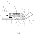
- FIG. 2 shows a schematic cross-sectional view of the spout 1.
- the cross-section is taken through an air intake conduit 17.
- the spout comprises the spout body 3 and detachable plate 5.
- a flow channel 19 is defined by the spout body and the plate.
- An aerator 11 is located within this flow channel, which is sized appropriately to reduce or prevent leakages of water around the edge of the aerator.
- Arrows A and B show the flows of water and air respectively into the aerator 11. Water enters the aerator at a water inlet 21, including a flow regulator as is conventional. Air enters the aerator at air inlet 23.
- Gasket 9 prevents water in the flow channel 19 from entering the air inlet 23 of the aerator 11, and additionally from leaking out of the air intake conduit 17 formed in the spout, by providing sealing between the aerator 11 and the flow channel 19 defined by the spout.
- the aerator 11 provides for mixing of the respective flows of air and water in such a way as to generate a suitably aerated stream of water C, which exits through the aerator outlet 25.
- the aerated stream of water passes through an outlet channel 26 downstream of the aerator, before exiting the spout through spout outlet 27.
- the outlet channel 26 is angled with respect to the longitudinal centreline of the aerator L, forming an angle of x° with this centreline. In the present embodiment, the angle is approximately 45°.
- the aerator 11 is not immediately adjacent the spout outlet 27, because there is a portion of the spout which extends downstream of the aerator, defining the outlet channel 26. As a result of this, the aerator is generally not visible in normal use of the spout, as it is concealed by the spout body 3 and plate 5. Such an arrangement may be more aesthetically appealing than an arrangement where the aerator is visible during normal use of the spout.
- the size and shape of the spout outlet may be varied accordingly to the desired size and shape of the stream of water which, in use, emerges from the outlet.
- the spout outlet is approximately rectangular (shown in more detail in Fig. 3 ), and accordingly the stream of water which, in use, issues from the spout is a ribbon, or blade of water, having an approximately rectangular cross section.
- FIG. 3(a) shows a view of the underside of the embodiment.
- the plate is attached to the spout body using screws 7 which engage with corresponding holes formed in the spout body 3.
- the plate therefore forms part of a wall of the spout.
- Two air intake conduits are formed through plate 5 (i.e. through a wall of the spout), either side of grub screw 13.
- Spout outlet 27 has an approximately rectangular shape, and accordingly a stream of water which passes through the outlet will also have an approximately rectangular cross section i.e. will be a ribbon or blade of water.
- Figure 3(b) shows a view from the same angle as Fig. 3(a) , with the plate 5 removed to show the flow channel 19 and aerator 11 within the spout body 3.
- the flow channel 19 narrows at the location at which the aerator is located, so that it is approximately the same width as the widest part of the aerator. This can help to provide sealing and prevent leakage of water around the sides of the aerator.
- Figure 4 shows an exploded view - as in Fig. 1 - of a modified embodiment, with refinements to improve the sealing of the construction.
- a first refinement is for the air intake 17.
- a supplementary seal locating member 8 in the form of a small rectangular metal plate, has a central hole 81 which anchors over a projecting boss 51 on the plate 5 around the hole for the grub screw 13.
- the locating member 8 sits in the through-hole or slot 15 in the gasket 9, and has air intake openings 82 to either side which align with the air intake openings 17 in the plate 5 and aerator.
- This feature provides more positive location and spacing of the co-operating elements, and ensures that the portions of the gasket around the air intake remain in place without shifting relative to the water flow path.
- a second refinement is seen at the front of the gasket and plate 5, where the gasket 9 is provided with a pair of dependent blocking lugs 91. These locate in corresponding notches 52 at the front of the plate, and in the assembled position are compressed to seal against the front edge of the surrounding spout body 3 opening at either side of the spout. They then prevent water from running by capillary action along the narrow groove between the plate 5 and the surrounding spout body 3, which might otherwise sometimes lead to dripping from the underside of the spout.
Landscapes
- Health & Medical Sciences (AREA)
- Life Sciences & Earth Sciences (AREA)
- Engineering & Computer Science (AREA)
- Hydrology & Water Resources (AREA)
- Public Health (AREA)
- Water Supply & Treatment (AREA)
- Domestic Plumbing Installations (AREA)
Applications Claiming Priority (1)
| Application Number | Priority Date | Filing Date | Title |
|---|---|---|---|
| GBGB1702266.6A GB201702266D0 (en) | 2017-02-10 | 2017-02-10 | Plumbing fixture with aerator |
Publications (1)
| Publication Number | Publication Date |
|---|---|
| EP3361015A1 true EP3361015A1 (fr) | 2018-08-15 |
Family
ID=58461969
Family Applications (1)
| Application Number | Title | Priority Date | Filing Date |
|---|---|---|---|
| EP18156265.3A Withdrawn EP3361015A1 (fr) | 2017-02-10 | 2018-02-12 | Accessoire de plomberie avec aérateur |
Country Status (2)
| Country | Link |
|---|---|
| EP (1) | EP3361015A1 (fr) |
| GB (1) | GB201702266D0 (fr) |
Cited By (3)
| Publication number | Priority date | Publication date | Assignee | Title |
|---|---|---|---|---|
| RU2742616C2 (ru) * | 2019-04-29 | 2021-02-09 | Азат Абулаесович Галлямов | Водоструйный аэратор с принудительной подачей воздуха под давлением для выпуска воды в санитарно-технической арматуре |
| WO2022057913A1 (fr) * | 2020-09-18 | 2022-03-24 | 厦门松霖科技股份有限公司 | Dispositif de sortie d'eau ayant deux sorties d'eau |
| EP4421254A1 (fr) * | 2023-02-21 | 2024-08-28 | Hansgrohe SE | Robinetterie sanitaire d'écoulement |
Citations (5)
| Publication number | Priority date | Publication date | Assignee | Title |
|---|---|---|---|---|
| DE1209515B (de) * | 1961-04-15 | 1966-01-20 | Hansa Metallwerke Ag | Vorrichtung zum Belueften eines unter Druck ausfliessenden Wasserstrahls mittels vomWasserstrom angesaugter Luft |
| DE3820837A1 (de) * | 1988-06-21 | 1990-01-04 | Wildfang Dieter Kg | Auslaufrohr fuer sanitaer-armaturen |
| WO2006077109A1 (fr) * | 2005-01-24 | 2006-07-27 | Neoperl Gmbh | Unite d'ecoulement sanitaire |
| DE202006007478U1 (de) * | 2006-05-09 | 2007-09-13 | Neoperl Gmbh | Sanitäre Auslaufeinheit |
| DE202009015868U1 (de) * | 2009-11-20 | 2011-04-07 | Neoperl Gmbh | Wasserführender Leitungsabschnitt mit einem Belüftungskanal |
-
2017
- 2017-02-10 GB GBGB1702266.6A patent/GB201702266D0/en not_active Ceased
-
2018
- 2018-02-12 EP EP18156265.3A patent/EP3361015A1/fr not_active Withdrawn
Patent Citations (5)
| Publication number | Priority date | Publication date | Assignee | Title |
|---|---|---|---|---|
| DE1209515B (de) * | 1961-04-15 | 1966-01-20 | Hansa Metallwerke Ag | Vorrichtung zum Belueften eines unter Druck ausfliessenden Wasserstrahls mittels vomWasserstrom angesaugter Luft |
| DE3820837A1 (de) * | 1988-06-21 | 1990-01-04 | Wildfang Dieter Kg | Auslaufrohr fuer sanitaer-armaturen |
| WO2006077109A1 (fr) * | 2005-01-24 | 2006-07-27 | Neoperl Gmbh | Unite d'ecoulement sanitaire |
| DE202006007478U1 (de) * | 2006-05-09 | 2007-09-13 | Neoperl Gmbh | Sanitäre Auslaufeinheit |
| DE202009015868U1 (de) * | 2009-11-20 | 2011-04-07 | Neoperl Gmbh | Wasserführender Leitungsabschnitt mit einem Belüftungskanal |
Cited By (3)
| Publication number | Priority date | Publication date | Assignee | Title |
|---|---|---|---|---|
| RU2742616C2 (ru) * | 2019-04-29 | 2021-02-09 | Азат Абулаесович Галлямов | Водоструйный аэратор с принудительной подачей воздуха под давлением для выпуска воды в санитарно-технической арматуре |
| WO2022057913A1 (fr) * | 2020-09-18 | 2022-03-24 | 厦门松霖科技股份有限公司 | Dispositif de sortie d'eau ayant deux sorties d'eau |
| EP4421254A1 (fr) * | 2023-02-21 | 2024-08-28 | Hansgrohe SE | Robinetterie sanitaire d'écoulement |
Also Published As
| Publication number | Publication date |
|---|---|
| GB201702266D0 (en) | 2017-03-29 |
Similar Documents
| Publication | Publication Date | Title |
|---|---|---|
| US9534362B2 (en) | Jet regulator | |
| US9353509B2 (en) | Elongate continuous flow controller with web-shaped or string-shaped flow restrictor | |
| US8708252B2 (en) | Sanitary installation part | |
| US20180298595A1 (en) | Faucet including an open waterway | |
| EP3361015A1 (fr) | Accessoire de plomberie avec aérateur | |
| JP5054434B2 (ja) | 節水部材及びそれを用いた節水具 | |
| JP6044816B1 (ja) | 泡沫吐水装置及び泡沫吐水ユニット | |
| US9062440B2 (en) | Sanitary functional unit | |
| US10934696B2 (en) | Jet regulator having a slit shaped recess tool engagement surface | |
| JPWO2011051998A1 (ja) | 節水栓 | |
| JP2017031689A (ja) | 水栓装置 | |
| JP4066459B2 (ja) | 吐水装置 | |
| CN101815828B (zh) | 射流调节器 | |
| US6823539B1 (en) | Cascading tub filler and overflow assembly | |
| US20210364098A1 (en) | Fluid mixing valve body assembly | |
| JP4154733B2 (ja) | 吐水装置 | |
| CN114541531B (zh) | 射流调节器 | |
| GB2526799A (en) | Fluid restriction nozzle for hand washing | |
| JP6620449B2 (ja) | 水栓装置 | |
| JP2018135673A (ja) | 吐水装置の製造方法 | |
| CN101617088B (zh) | 射流成形器 | |
| JP6629406B2 (ja) | 吐水装置及び浴槽装置 | |
| US20260022543A1 (en) | Faucet assembly and faucet structure | |
| JP4171895B2 (ja) | 接続配管の取付構造 | |
| AU2012238326B2 (en) | Jet regulator |
Legal Events
| Date | Code | Title | Description |
|---|---|---|---|
| PUAI | Public reference made under article 153(3) epc to a published international application that has entered the european phase |
Free format text: ORIGINAL CODE: 0009012 |
|
| AK | Designated contracting states |
Kind code of ref document: A1 Designated state(s): AL AT BE BG CH CY CZ DE DK EE ES FI FR GB GR HR HU IE IS IT LI LT LU LV MC MK MT NL NO PL PT RO RS SE SI SK SM TR |
|
| AX | Request for extension of the european patent |
Extension state: BA ME |
|
| STAA | Information on the status of an ep patent application or granted ep patent |
Free format text: STATUS: THE APPLICATION IS DEEMED TO BE WITHDRAWN |
|
| 18D | Application deemed to be withdrawn |
Effective date: 20190216 |