EP3361123A1 - Transmission manuelle pour véhicule - Google Patents
Transmission manuelle pour véhicule Download PDFInfo
- Publication number
- EP3361123A1 EP3361123A1 EP16853657.1A EP16853657A EP3361123A1 EP 3361123 A1 EP3361123 A1 EP 3361123A1 EP 16853657 A EP16853657 A EP 16853657A EP 3361123 A1 EP3361123 A1 EP 3361123A1
- Authority
- EP
- European Patent Office
- Prior art keywords
- speed
- gear
- speed change
- intermediate shaft
- shaft
- Prior art date
- Legal status (The legal status is an assumption and is not a legal conclusion. Google has not performed a legal analysis and makes no representation as to the accuracy of the status listed.)
- Withdrawn
Links
- 230000005540 biological transmission Effects 0.000 title claims description 66
- 230000008859 change Effects 0.000 claims description 205
- 230000007246 mechanism Effects 0.000 description 59
- 230000009467 reduction Effects 0.000 description 59
- 101150023475 Gfi1 gene Proteins 0.000 description 24
- 230000003247 decreasing effect Effects 0.000 description 4
- 230000004323 axial length Effects 0.000 description 3
- 230000004044 response Effects 0.000 description 3
- 230000004048 modification Effects 0.000 description 2
- 238000012986 modification Methods 0.000 description 2
- 230000007935 neutral effect Effects 0.000 description 2
- 230000000694 effects Effects 0.000 description 1
- 238000004904 shortening Methods 0.000 description 1
Images











Classifications
-
- F—MECHANICAL ENGINEERING; LIGHTING; HEATING; WEAPONS; BLASTING
- F16—ENGINEERING ELEMENTS AND UNITS; GENERAL MEASURES FOR PRODUCING AND MAINTAINING EFFECTIVE FUNCTIONING OF MACHINES OR INSTALLATIONS; THERMAL INSULATION IN GENERAL
- F16H—GEARING
- F16H3/00—Toothed gearings for conveying rotary motion with variable gear ratio or for reversing rotary motion
- F16H3/02—Toothed gearings for conveying rotary motion with variable gear ratio or for reversing rotary motion without gears having orbital motion
- F16H3/08—Toothed gearings for conveying rotary motion with variable gear ratio or for reversing rotary motion without gears having orbital motion exclusively or essentially with continuously meshing gears, that can be disengaged from their shafts
- F16H3/087—Toothed gearings for conveying rotary motion with variable gear ratio or for reversing rotary motion without gears having orbital motion exclusively or essentially with continuously meshing gears, that can be disengaged from their shafts characterised by the disposition of the gears
- F16H3/093—Toothed gearings for conveying rotary motion with variable gear ratio or for reversing rotary motion without gears having orbital motion exclusively or essentially with continuously meshing gears, that can be disengaged from their shafts characterised by the disposition of the gears with two or more countershafts
-
- F—MECHANICAL ENGINEERING; LIGHTING; HEATING; WEAPONS; BLASTING
- F16—ENGINEERING ELEMENTS AND UNITS; GENERAL MEASURES FOR PRODUCING AND MAINTAINING EFFECTIVE FUNCTIONING OF MACHINES OR INSTALLATIONS; THERMAL INSULATION IN GENERAL
- F16H—GEARING
- F16H3/00—Toothed gearings for conveying rotary motion with variable gear ratio or for reversing rotary motion
- F16H3/02—Toothed gearings for conveying rotary motion with variable gear ratio or for reversing rotary motion without gears having orbital motion
- F16H3/08—Toothed gearings for conveying rotary motion with variable gear ratio or for reversing rotary motion without gears having orbital motion exclusively or essentially with continuously meshing gears, that can be disengaged from their shafts
- F16H2003/0822—Toothed gearings for conveying rotary motion with variable gear ratio or for reversing rotary motion without gears having orbital motion exclusively or essentially with continuously meshing gears, that can be disengaged from their shafts characterised by the arrangement of at least one reverse gear
-
- F—MECHANICAL ENGINEERING; LIGHTING; HEATING; WEAPONS; BLASTING
- F16—ENGINEERING ELEMENTS AND UNITS; GENERAL MEASURES FOR PRODUCING AND MAINTAINING EFFECTIVE FUNCTIONING OF MACHINES OR INSTALLATIONS; THERMAL INSULATION IN GENERAL
- F16H—GEARING
- F16H3/00—Toothed gearings for conveying rotary motion with variable gear ratio or for reversing rotary motion
- F16H3/02—Toothed gearings for conveying rotary motion with variable gear ratio or for reversing rotary motion without gears having orbital motion
- F16H3/08—Toothed gearings for conveying rotary motion with variable gear ratio or for reversing rotary motion without gears having orbital motion exclusively or essentially with continuously meshing gears, that can be disengaged from their shafts
- F16H3/087—Toothed gearings for conveying rotary motion with variable gear ratio or for reversing rotary motion without gears having orbital motion exclusively or essentially with continuously meshing gears, that can be disengaged from their shafts characterised by the disposition of the gears
- F16H3/093—Toothed gearings for conveying rotary motion with variable gear ratio or for reversing rotary motion without gears having orbital motion exclusively or essentially with continuously meshing gears, that can be disengaged from their shafts characterised by the disposition of the gears with two or more countershafts
- F16H2003/0931—Toothed gearings for conveying rotary motion with variable gear ratio or for reversing rotary motion without gears having orbital motion exclusively or essentially with continuously meshing gears, that can be disengaged from their shafts characterised by the disposition of the gears with two or more countershafts each countershaft having an output gear meshing with a single common gear on the output shaft
-
- F—MECHANICAL ENGINEERING; LIGHTING; HEATING; WEAPONS; BLASTING
- F16—ENGINEERING ELEMENTS AND UNITS; GENERAL MEASURES FOR PRODUCING AND MAINTAINING EFFECTIVE FUNCTIONING OF MACHINES OR INSTALLATIONS; THERMAL INSULATION IN GENERAL
- F16H—GEARING
- F16H2200/00—Transmissions for multiple ratios
- F16H2200/0008—Transmissions for multiple ratios specially adapted for front-wheel-driven vehicles
-
- F—MECHANICAL ENGINEERING; LIGHTING; HEATING; WEAPONS; BLASTING
- F16—ENGINEERING ELEMENTS AND UNITS; GENERAL MEASURES FOR PRODUCING AND MAINTAINING EFFECTIVE FUNCTIONING OF MACHINES OR INSTALLATIONS; THERMAL INSULATION IN GENERAL
- F16H—GEARING
- F16H2200/00—Transmissions for multiple ratios
- F16H2200/003—Transmissions for multiple ratios characterised by the number of forward speeds
- F16H2200/0052—Transmissions for multiple ratios characterised by the number of forward speeds the gear ratios comprising six forward speeds
Definitions
- This invention relates to a manual transmission for a vehicle.
- M/T a manual transmission
- the M/T includes an input shaft which forms a power transmitting system with the output shaft of the engine therebetween, an output shaft which forms another power transmitting system with the drive wheel therebetween and two intermediate shafts (first intermediate shaft and a second intermediate shaft), each mutually being arranged in parallel with each other and rotatably supported at a housing.
- Fig. 16 shows an example of one type of M/T (six-speed M/T) having six forward speed change stages (first to sixth speed).
- M/T shown in Fig. 16 has an input shaft Ai on which a first speed drive gear G1 i, a second speed drive gear G2i, a first common drive gear G45i which is used commonly for a fourth speed drive gear and a fifth speed drive gear, a third speed drive gear G3i and a sixth speed drive gear G6i are arranged in order from a side close to the engine E/G, being restricted from a relative rotation with the input shaft Ai.
- a first final drive gear Gfi1 is arranged on the first intermediate shaft A1, being restricted from a relative rotation therewith.
- a first speed driven gear G1o which is arranged always being in gear-engagement with the first speed drive gear G1i
- a second speed driven gear G2o being in gear-engagement with the second speed drive gear G2i
- a fourth speed driven gear G4o being in gear-engagement with the first common drive gear G45i
- a third speed driven gear G3o being in gear-engagement with the third speed drive gear G3i are relatively rotatably arranged on the first intermediate shaft A1.
- These gears Gfi1, G1o, G2o, G4o and G3o are arranged on the first intermediate shaft A1 in this order from a side close to the engine E/G.
- a second final drive gear Gfi2 is arranged on the second intermediate shaft A2, being restricted from a relative rotation therewith.
- a fifth speed driven gear G5o which is arranged always being in gear-engagement with the first common drive gear G45i and a sixth speed driven gear G6o being in gear-engagement with the sixth speed drive gear G6i are relatively rotatably arranged on the second intermediate shaft A2.
- These gears Gfi2, G5o and G6o are arranged on the second intermediate shaft A2 in this order from a side close to the engine E/G.
- a final driven gear Gfo is arranged on the output shaft Ao, always being in gear-engagement with the first final gear Gfi1 and the second final gear Gfi2 and being restricted from a relative rotation with the output shaft Ao.
- a first speed (second speed) power transmitting system is established by the engagement of the sleeve S1 arranged on the first intermediate shaft A1, allowing an axial movement therewith, but restricting a relative rotation therewith, with the first speed driven gear G1o (second speed driven gear G2o).
- the power is transmitted from the input shaft Ai to the output shaft Ao via the first speed drive gear G1i (second speed drive gear G2i), the first speed driven gear G1o (second speed driven gear G2o), the sleeve S1, the first intermediate shaft A1, the first final drive gear Gfi1 and the final driven gear Gfo according to this first speed (second speed) power transmitting system.
- a third speed (fourth speed) power transmitting system is established by the engagement of the sleeve S2 arranged on the first intermediate shaft A1, allowing an axial movement therewith, but restricting a relative rotation therewith, with the third speed driven gear G3o (fourth speed driven gear G4o).
- the power is transmitted from the input shaft Ai to the output shaft Ao via the third speed drive gear G3i (the first common drive gear G45i), the third speed driven gear G3o (the fourth speed driven gear G4o), the sleeve S2, the first intermediate shaft A1, the first final drive gear Gfi1 and the final driven gear Gfo according to this third speed (fourth speed) power transmitting system.
- a fifth speed (sixth speed) power transmitting system is established by the engagement of the sleeve S3 arranged on the second intermediate shaft A2, allowing an axial movement therewith, but restricting a relative rotation therewith, with the fifth speed driven gear G5o (sixth speed driven gear G6o).
- the power is transmitted from the input shaft Ai to the output shaft Ao via the first common drive gear G45i (the sixth speed drive gear G6i), the fifth speed driven gear G5o (the sixth speed driven gear G6o), the sleeve S3, the second intermediate shaft A2, the second final drive gear Gfi2 and the final driven gear Gfo according to this fifth speed (sixth speed) power transmitting system.
- Fig. 17 shows an example of another M/T (six-speed M/T) which has six speed change stages formed by six forward speed change stages (first to sixth speed) and one speed change stage for reverse drive.
- the six-speed M/T includes an input shaft Ai on which a first speed drive gear G1i, a second speed drive gear G2i, a first common drive gear G45i which is used commonly for a fourth speed drive gear and a fifth speed drive gear, a third speed drive gear G3i and a sixth speed drive gear G6i are arranged in order from a side close to the engine E/G, being restricted from a relative rotation with the input shaft Ai.
- a first final drive gear Gfi1 is arranged on the first intermediate shaft A1, being restricted from a relative rotation therewith.
- a first speed driven gear G1o which is arranged always being in gear-engagement with the first speed drive gear G1i
- a second speed driven gear G2o being in gear-engagement with the second speed drive gear G2i
- a fourth speed driven gear G4o being in gear-engagement with the first common drive gear G45i
- a third speed driven gear G3o being in gear-engagement with the third speed drive gear G3i are relatively rotatably arranged on the first intermediate shaft A1.
- These gears Gfi1, G1o, G2o, G4o and G3o are arranged on the first intermediate shaft A1 in this order from a side close to the engine E/G.
- a second final drive gear Gfi2 is arranged on the second intermediate shaft A2, being restricted from a relative rotation therewith.
- a reverse speed driven gear GRo2 is relatively rotatably arranged on the second intermediate shaft A2.
- a fifth speed driven gear G5o which is arranged always being in gear-engagement with the first common drive gear G45i and a sixth speed driven gear G6o being in gear-engagement with the sixth speed drive gear G6i are relatively rotatably arranged on the second intermediate shaft A2.
- These gears Gfi2, GRo2, G5o and G6o are arranged on the second intermediate shaft A2 in this order from a side close to the engine E/G.
- a final driven gear Gfo is arranged on the output shaft Ao, always being in gear-engagement with the first final gear Gfi1 and the second final gear Gfi2 and being restricted from a relative rotation with the output shaft Ao.
- a reverse drive first drive gear GRi which is always in gear-engagement with the first speed drive gear G1i and a second drive gear GRo1 which is always in gear-engagement with the reverse drive driven gear GRo2 and at the same time rotated with the reverse drive first drive gear GRi are provided on an idle shaft A5 and are relatively rotatable therewith.
- a first speed (second) speed power transmitting system is established by the engagement of the sleeve S1 arranged on the first intermediate shaft A1, allowing an axial movement therewith, but restricting a relative rotation therewith, with the first speed driven gear G1o (second speed driven gear G2o).
- the power is transmitted from the input shaft Ai to the output shaft Ao via the first speed drive gear G1i (second speed drive gear G2i), the first speed driven gear G1o (second speed driven gear G2o), the sleeve S1, the first intermediate shaft A1, the first final drive gear Gfi1 and the final driven gear Gfo according to this first speed (second speed) power transmitting system.
- a third speed (fourth speed) power transmitting system is established by the engagement of the sleeve S2 arranged on the first intermediate shaft A1, allowing an axial movement therewith, but restricting a relative rotation therewith, with the third speed driven gear G3o (fourth speed driven gear G4o).
- the power is transmitted from the input shaft Ai to the output shaft Ao via the third speed drive gear G3i (the first common drive gear G45i), the third speed driven gear G3o (the fourth speed driven gear G4o), the sleeve S2, the first intermediate shaft A1, the first final drive gear Gfi1 and the final driven gear Gfo according to this third speed (fourth speed) power transmitting system.
- a fifth speed (sixth speed) power transmitting system is established by the engagement of the sleeve S3 arranged on the second intermediate shaft A2, allowing an axial movement therewith, but restricting a relative rotation therewith, with the fifth speed driven gear G5o (sixth speed driven gear G6o).
- the power is transmitted from the input shaft Ai to the output shaft Ao via the first common drive gear G45i (the sixth speed drive gear G6i), the fifth speed driven gear G5o (the sixth speed driven gear G6o), the sleeve S3, the second intermediate shaft A2, the second final drive gear Gfi2 and the final driven gear Gfo according to this fifth speed (sixth speed) power transmitting system.
- a reverse drive power transmitting system is established by the engagement of the sleeve S4 arranged on the second intermediate shaft A2, allowing an axial movement therewith, but restricting a relative rotation therewith, with the reverse drive driven gear GRo2.
- the power is transmitted from the input shaft Ai to the output shaft Ao via the first speed drive gear G1i, the reverse drive first drive gear GRi, the second drive gear GRo1, the reverse drive driven gear GRo2, the sleeve S4, the second intermediate shaft A2, the second final drive gear Gfi2 and the final driven gear Gfo according to this reverse drive power transmitting system.
- Patent Document 1 JP2011-43180 A
- the engine output shaft is arranged along in the width direction relative to the vehicle.
- the input shaft of the M/T is connected to the engine output shaft co-axially thereto via the clutch.
- the M/T is arranged in the vicinity of the engine via the clutch so that the input shaft of the M/T is arranged along in the width direction of the vehicle.
- the engine-clutch-M/T assembly is disposed in the engine compartment of the vehicle between the right and left side frames which space is relatively narrow. It is, therefore, the entire length of the M/T in an axial direction is desired to be shortened.
- a gear which is provided on a shaft with a play and fixed thereto to be engageable with or disengageable from the shaft is defined to be an "idler gear” and a pair of such idler gears which is engageable with one sleeve is defined to be a "gear set”.
- the present invention was made in consideration of the above issues and problems of the related arts and it is an object of the invention to provide a manual transmission for a vehicle having a plurality of speed change stages, being interposed in a power transmitting system which connects the output shaft of the power source of the vehicle with the drive wheel.
- the idler gears are idly rotatably provided on the shaft on which the idler gears are to be fixed to be engageable therewith or disengageable therefrom and without concentrating to the two intermediate shafts, the idler gears are arranged on the three intermediate shafts and further on the input shaft. Accordingly, the axial length of the manual transmission for a vehicle having input shaft, output shaft and a plurality of intermediate shafts can be shortened.
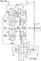
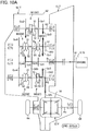
- the M/T according to the first embodiment includes six forward drive speed change stages (first through sixth speed) and is applicable particularly to the FF-vehicle wherein the output shaft 61 of the engine E/G is arranged in a transverse width direction relative to the vehicle. It is noted that the explanation for the reverse will be omitted in this description.
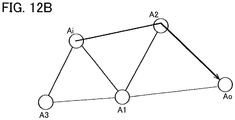
- the M/T includes five shafts, i.e., an input shaft Ai, a first intermediate shaft A1, a second intermediate shaft A2, a third intermediate shaft A3 and an output shaft Ao. These shafts are rotatably supported on a housing 62 through a plurality of bearings (or bushes) which is fixed to the housing 62 and are mutually eccentrically positioned to be in parallel with one another.
- the input shaft Ai is connected to an output shaft 61 of an engine E/G through a clutch C/T.
- the output shaft Ao is connected to drive wheels 64 (front two wheels) via a connecting mechanism (not shown).
- the manual transmission M/T for vehicle is arranged in a vicinity of the engine E/G via the clutch C/T such that the shafts of the manual transmission M/T are positioned in a width direction of the vehicle.
- a first speed drive gear Gi1 On the input shaft Ai, as the drive gears for establishing forward speed change stages, a first speed drive gear Gi1, a first common drive gear Gi35 which is commonly used as a third speed drive gear and a fifth speed drive gear, a second speed drive gear Gi2 and a second common drive gear Gi46 which is commonly used as a fourth speed drive gear and a sixth speed drive gear are coaxially provided in order from a side close to the engine E/G (clutch C/T).
- the first speed drive gear Gi1, the first common drive gear Gi35, the second speed drive gear Gi2 and the second common drive gear Gi46 are the drive fixed gears fixed to the input shaft Ai.
- a fifth speed driven gear Go5 and a sixth speed driven gear Go6 are coaxially provided in order from a side close to the engine E/G.
- the fifth speed driven gear Go5 and the sixth speed driven gear Go6 are provided on the first intermediate shaft A1, allowing a rotation relative to the first intermediate shaft A1 and are the driven idler gears fixed on the first intermediate shaft A1 for engageable therewith or disengageable therefrom.
- These driven idler gears are the idler gear defined in this invention.
- the fifth speed driven gear Go5 and the sixth speed driven gear Go6 are always engaging with the first common drive gear Gi35 and the second common drive gear Gi46, respectively.
- the fifth speed and the sixth speed correspond to the "speed change stage of the first group" of the invention.
- a first final drive gear Gfi1 and a first connecting gear Gc1 are provided coaxially in a position closer to the engine E/G than the position of the fifth speed driven gear Go5, in order from a side close to the engine E/G.
- the first final drive gear Gfi1 is a fixed gear fixed on the first intermediate shaft A1 and the first connecting gear Gc1 is rotatably supported on the first intermediate shaft A1.
- a third speed driven gear Go3 and a fourth speed driven gear Go4 are coaxially provided in order from a side close to the engine E/G.
- the third speed driven gear Go3 and the fourth speed driven gear Go4 are the driven idler gears and are the idler gears defined in this invention.
- the third speed driven gear Go3 and the fourth speed driven gear Go4 are always engaging with the first common drive gear Gi35 and the second common drive gear Gi46, respectively.
- the third speed and the fourth speed correspond to the "speed change stage of the second group" of the invention.
- a second final drive gear Gfi2 and a second connecting gear Gc2 are provided coaxially in a position closer to the engine E/G than the position of the third speed driven gear Go3, in order from a side close to the engine E/G.
- the second final drive gear Gfi2 is a fixed gear fixed on the second intermediate shaft A2 and the second connecting gear Gc2 also is a fixed gear fixed on the second intermediate shaft A2.
- the second connecting gear Gc2 is always engaging with the first connecting gear Gc1.
- a first speed driven gear Go1 and a second speed driven gear Go2 are coaxially provided in order from a side close to the engine E/G.
- the first speed driven gear Go1 and the second speed driven gear Go2 are the driven idler gears and are the idler gears defined in this invention.
- the first speed driven gear Go1 and a second speed driven gear Go2 are always engaging with the first drive gear Gi1 and the second drive gear Gi2, respectively.
- the first speed and the second speed correspond to the "speed change stage of the third group" of the invention.
- a third connecting gear Gc3 is provided coaxially in a position closer to the engine E/G than the position of the first speed driven gear Go1.
- the third connecting gear Gc3 is a fixed gear fixed on the third intermediate shaft A3.
- the third connecting gear Gc3 is always engaging with the first connecting gear Gc1.
- a final driven gear Gfo which is formed as a unit with the housing 70 of a differential gear mechanism D/F having a well-known structure is coaxially provided.
- the final driven gear Gfo is a fixed gear.
- the final driven gear Gfo is always engaging with the first final drive gear Gfi1 and the second final drive gear Gfi2, respectively.
- the manual transmission M/T for vehicle includes a first shifting mechanism M1, a second shifting mechanism M2 and a third shifting mechanism M3.
- the shifting of the speed change stage of the manual transmission M/T is achieved by the operation of the first shifting mechanism M1, the second shifting mechanism M2 and the third shifting mechanism M3.
- the first shifting mechanism M1, the second shifting mechanism M2 and the third shifting mechanism M3 are operated in response to a shift lever (not shown) via a plurality of link mechanisms (not shown) which connects the shift lever with the first shifting mechanism M1, the second shifting mechanism M2 and the third shifting mechanism M3.
- the first shifting mechanism M1 is provided on the third intermediate shaft A3 between the first speed driven gear Go1 and the second speed driven gear Go2.
- the first shifting mechanism M1 includes a first connecting piece 11 which is provided coaxially with the third intermediate shaft A3 and rotates therewith as a unit, a second connecting piece 12 which is provided coaxially with the first speed driven gear Go1 and rotates therewith as a unit, a third connecting piece 13 which is provided coaxially with the second speed driven gear Go2 and rotates therewith as a unit and a sleeve S1 which is movably provided in an axial direction with respect to the third intermediate shaft A3.
- the sleeve S1 is operated in response to the operation of the shift lever via the link mechanisms explained above.
- the sleeve S1 is inserted into the first connecting piece 11, the second connecting piece 12 and the third connecting piece 13 and in spline connection therewith.
- a non-connected state position shown in Fig. 1
- the first speed driven gear Go1 and the second speed driven gear Go2 are both rotatable relative to the third intermediate shaft A3.
- the second speed driven gear Go2 When the sleeve S1 is in a first speed state (the position of the sleeve S1 in Fig. 1 being moved to the right in Fig. 1 ) that is a state in a splined connection with the first connecting piece 11 and the second connecting piece 12, the second speed driven gear Go2 is rotatable relative to the third intermediate shaft A3, but the first speed driven gear Go1 is prohibited from relative rotation with the third intermediate shaft A3.
- the first shifting mechanism M1 functions to fix the first speed driven gear Go1 to the third intermediate shaft A3 on which the first speed driven gear Go1 is provided.
- the first speed driven gear Go1 is rotatable relative to the third intermediate shaft A3, but the second speed driven gear Go2 is prohibited from relative rotation with the third intermediate shaft A3.
- the first shifting mechanism M1 selects one of the non-connected state, the first speed state and the second speed state according to the position of the sleeve S1 which is operated by the shift lever. It is noted ere that the structures of the second and the third shifting mechanisms M2 and M3 are similar to the structure of the first shifting mechanism M1 and the detail explanation thereof will be omitted.
- the second shifting mechanism M2 is provided on the second intermediate shaft A2 between the third speed driven gear Go3 and the fourth speed driven gear Go4.
- the second shifting mechanism M2 selects one of the non-connected state, the third speed state and the fourth speed state according to the position of the sleeve S2 which is operated by the shift lever.
- the third shifting mechanism M3 is provided on the first intermediate shaft A1 between the fifth speed driven gear Go5 and the sixth speed driven gear Go6.
- the third shifting mechanism M3 selects one of the non-connected state, the fifth speed state and the sixth speed state according to the position of the sleeve S3 which is operated by the shift lever.
- the speed change stage shifting device 66 is formed by the first shifting mechanism M1, the second shifting mechanism M2 and the third shifting mechanism M3.
- the speed change stage shifting device 66 fixes an idler gear corresponding to a selected one speed change stage selected among the plurality of speed change stages (first speed, second speed, third speed, fourth speed, fifth speed and sixth speed) to a shaft on which the idler gear is provided, to be engageable with or disengageable from the shaft.
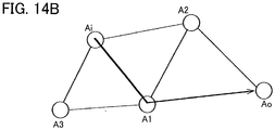
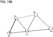
- the power transmitting system is established in the manual transmission M/T for a vehicle in which the power is transmitted from the input shaft Ai to the output shaft Ao via the first speed drive gear Gi1, the first speed driven gear Go1, the second connecting piece 12, the sleeve S1, the first connecting piece 11, the third intermediate shaft A3, the third connecting gear Gc3, the first connecting gear Gc1, the second connecting gear Gc2, the second intermediate shaft A2, the second final drive gear Gfi2 and the final driven gear Gfo.
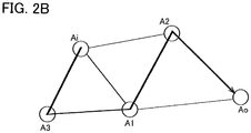
- the power transmitting system is established in the manual transmission M/T for a vehicle in which the power is transmitted from the input shaft Ai to the output shaft Ao via the second speed drive gear Gi2, the second speed driven gear Go2, the third connecting piece 13, the sleeve S1, the first connecting piece 11, the third intermediate shaft A3, the third connecting gear Gc3, the first connecting gear Gc1, the second connecting gear Gc2, the second intermediate shaft A2, the second final drive gear Gfi2 and the final driven gear Gfo.
- the third connecting piece 13 the sleeve S1 the first connecting piece 11, the third intermediate shaft A3, the third connecting gear Gc3, the first connecting gear Gc1, the second connecting gear Gc2, the second intermediate shaft A2, the second final drive gear Gfi2 and the final driven gear Gfo.
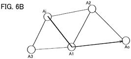
- the sleeve S2 is shifted to the "third speed state” and the other sleeves S1 and S3 are shifted to the "non-connected state".
- the power transmitting system is established in the manual transmission M/T for a vehicle in which the power is transmitted from the input shaft Ai to the output shaft Ao via the first common drive gear Gi35, the third speed driven gear Go3, the fifth connecting piece 22, the sleeve S2, the fourth connecting piece 21, the second intermediate shaft A2, the second final gear Gfi2 and the final driven gear Gfo.
- the first common drive gear Gi35 the third speed driven gear Go3
- the fifth connecting piece 22 the sleeve S2
- the fourth connecting piece 21 the second intermediate shaft A2
- the second final gear Gfi2 the final driven gear Gfo.
- the sleeve S2 is shifted to the "fourth speed state" and the other sleeves S1 and S3 are shifted to the "non-connected state".
- the power transmitting system is established in the manual transmission M/T for a vehicle in which the power is transmitted from the input shaft Ai to the output shaft Ao via the second common drive gear Gi46, the fourth speed driven gear Go4, the sixth connecting piece 23, the sleeve S2, the fourth connecting piece 21, the second intermediate shaft A2, the second final gear Gfi2 and the final driven gear Gfo.
- the power transmitting system is established in the manual transmission M/T for a vehicle in which the power is transmitted from the input shaft Ai to the output shaft Ao via the second common drive gear Gi46, the fourth speed driven gear Go4, the sixth connecting piece 23, the sleeve S2, the fourth connecting piece 21, the second intermediate shaft A2, the second final gear Gfi2 and the final driven gear Gfo.
- the sleeve S3 is shifted to the "fifth speed state" and the other sleeves S1 and S2 are shifted to the "non-connected state".
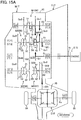
- the power transmitting system is established in the manual transmission M/T for a vehicle in which the power is transmitted from the input shaft Ai to the output shaft Ao via the first common drive gear Gi35, the fifth speed driven gear Go5, the eighth connecting piece 32, the sleeve S3, the seventh connecting piece 31, the first intermediate shaft A1, the first final gear Gfi1 and the final driven gear Gfo.
- the sleeve S3 is shifted to the "sixth speed state" and the other sleeves S1 and S2 are shifted to the "non-connected state".
- the power transmitting system is established in the manual transmission M/T for a vehicle in which the power is transmitted from the input shaft Ai to the output shaft Ao via the second common drive gear Gi46, the sixth speed driven gear Go6, the ninth connecting piece 33, the sleeve S3, the seventh connecting piece 31, the first intermediate shaft A1, the first final gear Gfi1 and the final driven gear Gfo.
- Fig. 7A the power transmitting system is established in the manual transmission M/T for a vehicle in which the power is transmitted from the input shaft Ai to the output shaft Ao via the second common drive gear Gi46, the sixth speed driven gear Go6, the ninth connecting piece 33, the sleeve S3, the seventh connecting piece 31, the first intermediate shaft A1, the first final gear Gfi1 and the final driven gear Gfo.
- the six forward speed driven gears Go1, Go2, Go3, Go4, Go5 and Go6 are the idler gears defined in this invention and they are sorted and arranged on the three intermediate shafts, i.e., two idler gears are arranged on each of the three shafts. Accordingly, compared to the M/T described in the Background of the Technology (six driven gears are sorted and arranged on the two intermediate shafts.: See Fig. 16 ), the maximum number of idler gears sorted to each intermediate shaft can be decreased. In detail, according to the conventional M/T shown in Fig.
- the two "gear sets” i.e., four idler gears
- only one "gear set” i.e., two idler gears
- the length in an axial direction of the manual transmission M/T can be further shortened.
- the M/T according to the second embodiment includes six forward drive speed change stages (first through sixth speed) and one reverse drive speed change stage (reverse) and is applicable particularly to the FF-vehicle wherein the output shaft 61 of the engine E/G is arranged in a transverse width direction relative to the vehicle. It is noted that in this embodiment, the structures shown in Figs. 1 , 2A through 7A and 2B through 7B are similar to those of the first embodiment and the explanation thereof will be omitted in this description.
- the manual transmission M/T for a vehicle further includes the fourth shifting mechanism M4 and the fifth shifting mechanism M5, in addition to the first, second and third shifting mechanisms M1, M2 and M3 shown in fig. 1 .
- the shifting of the speed change stage of the manual transmission M/T is achieved by the operation of the first shifting mechanism M1, the second shifting mechanism M2 and the third shifting mechanism M3, the fourth shifting mechanism M4 and the fifth shifting mechanism M5.
- the first shifting mechanism M1, the second shifting mechanism M2, the third shifting mechanism M3, the fourth shifting mechanism M4 and the fifth shifting mechanism M5 are operated in response to a shift lever (not shown) via a plurality of link mechanisms (not shown) which connects the shift lever with the first shifting mechanism M1, the second shifting mechanism M2, the third shifting mechanism M3, the fourth shifting mechanism M4 and the fifth shifting mechanism M5.
- the fourth shifting mechanism M4 is provided on the first intermediate shaft A1 between the fifth speed driven gear Go5 and the first connecting gear Gc1.
- the first connecting gear Gc1 is relatively rotatably provided on the first intermediate shaft A1 and is fixed engageably with or disengageably from the first intermediate shaft A1 by the fourth shifting mechanism M4, as shown in Fig. 8 . Accordingly, the first connecting gear Gc1 according to the second embodiment corresponds to the idler gear defined by the invention.
- the fourth shifting mechanism M4 selects one of the non-connected state and a connected state with the first connecting gear Gc1 according to the position of the sleeve S4 which is operated by the shift lever.
- the fifth shifting mechanism M5 is provided on the second intermediate shaft A2 between the third speed driven gear Go3 and the second connecting gear Gc2.
- the second connecting gear Gc2 is relatively rotatably provided on the second intermediate shaft A2 and is fixed engageably with or disengageably from the second intermediate shaft A2 by the fifth shifting mechanism M5, as shown in Fig. 8 .
- the second connecting gear Gc2 according to the second embodiment corresponds to the idler gear defined by the invention.
- the fifth shifting mechanism M5 selects one of the non-connected state and a connected state with the second connecting gear Gc2 according to the position of the sleeve S5 which is operated by the shift lever.
- a group shifting device 67 is formed by the fourth shifting mechanism M4 and the fifth shifting mechanism M5. The group shifting device 67 fixes a selected connecting gear selected from the first and the second connecting gears Gc1 and Gc2 to a shaft on which the selected connecting gear is provided, to be engageable with or disengageable from the shaft.
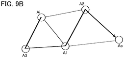
- the power transmitting system is established in the manual transmission M/T for a vehicle in which the power is transmitted from the input shaft Ai to the output shaft Ao via the first speed drive gear Gi1, the first speed driven gear Go1, the second connecting piece 12, the sleeve S1, the first connecting piece 11, the third intermediate shaft A3, the third connecting gear Gc3, the first connecting gear Gc1, the second connecting gear Gc2, the thirteenth connecting piece 52, the sleeve S5, the twelfth connecting piece 51, the second intermediate shaft A2, the second final drive gear Gfi2 and the final driven gear Gfo.
- the power transmitting system is established in the manual transmission M/T for a vehicle in which the power is transmitted from the input shaft Ai to the output shaft Ao via the second speed drive gear Gi2, the second speed driven gear Go2, the third connecting piece 13, the sleeve S1, the first connecting piece 11, the third intermediate shaft A3, the third connecting gear Gc3, the first connecting gear Gc1, the second connecting gear Gc2, thirteenth connecting piece 52, the sleeve S5, the twelfth connecting piece 51, the second intermediate shaft A2, the second final drive gear Gfi2 and the final driven gear Gfo.
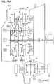
- the sleeve S2 When the shift lever is operated to the position corresponding to the third speed, as shown in Fig. 11A , the sleeve S2 is shifted to the "third speed state" and the other sleeves S1,S3, S4 and S5 are shifted to the "non-connected state".
- the power transmitting system is established in the manual transmission M/T for a vehicle in which the power is transmitted from the input shaft Ai to the output shaft Ao via the first common drive gear Gi35, the third speed driven gear Go3, the fifth connecting piece 22, the sleeve S2, the fourth connecting piece 21, the second intermediate shaft A2, the second final gear Gfi2 and the final driven gear Gfo.
- the first common drive gear Gi35 the third speed driven gear Go3
- the fifth connecting piece 22 the sleeve S2
- the fourth connecting piece 21 the second intermediate shaft A2
- the second final gear Gfi2 the final driven gear Gfo.
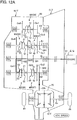
- the sleeve S2 When the shift lever is operated to the position corresponding to the fourth speed, as shown in Fig. 12A , the sleeve S2 is shifted to the "fourth speed state" and the other sleeves S1, S3, S4 and S5 are shifted to the "non-connected state".
- the power transmitting system is established in the manual transmission M/T for a vehicle in which the power is transmitted from the input shaft Ai to the output shaft Ao via the second common drive gear Gi46, the fourth speed driven gear Go4, the sixth connecting piece 23, the sleeve S2, the fourth connecting piece 21, the second intermediate shaft A2, the second final gear Gfi2 and the final driven gear Gfo.
- the power transmitting system is established in the manual transmission M/T for a vehicle in which the power is transmitted from the input shaft Ai to the output shaft Ao via the second common drive gear Gi46, the fourth speed driven gear Go4, the sixth connecting piece 23, the sleeve S2, the fourth connecting piece 21, the second intermediate shaft A2, the second final
- the sleeve S3 is shifted to the "fifth speed state" and the other sleeves S1, S2, S4 and S5 are shifted to the "non-connected state".
- the power transmitting system is established in the manual transmission M/T for a vehicle in which the power is transmitted from the input shaft Ai to the output shaft Ao via the first common drive gear Gi35, the fifth speed driven gear Go5, the eighth connecting piece 32, the sleeve S3, the seventh connecting piece 31, the first intermediate shaft A1, the first final gear Gfi1 and the final driven gear Gfo.
- the power transmitting system is established in the manual transmission M/T for a vehicle in which the power is transmitted from the input shaft Ai to the output shaft Ao via the first common drive gear Gi35, the fifth speed driven gear Go5, the eighth connecting piece 32, the sleeve S3, the seventh connecting piece 31, the first intermediate shaft A1, the first final gear Gfi1 and the final driven gear Gfo.
- the sleeve S3 is shifted to the "sixth speed state" and the other sleeves S1, S2, S4 and S5 are shifted to the "non-connected state".
- the power transmitting system is established in the manual transmission M/T for a vehicle in which the power is transmitted from the input shaft Ai to the output shaft Ao via the second common drive gear Gi46, the sixth speed driven gear Go6, the ninth connecting piece 33, the sleeve S3, the seventh connecting piece 31, the first intermediate shaft A1, the first final gear Gfi1 and the final driven gear Gfo.
- the power transmitting system is established in the manual transmission M/T for a vehicle in which the power is transmitted from the input shaft Ai to the output shaft Ao via the second common drive gear Gi46, the sixth speed driven gear Go6, the ninth connecting piece 33, the sleeve S3, the seventh connecting piece 31, the first intermediate shaft A1, the first final gear Gfi1 and the final driven gear Gfo.
- the power transmitting system is established in the manual transmission M/T for a vehicle in which the power is transmitted from the input shaft Ai to the output shaft Ao via the first speed drive gear Gi1, the first speed driven gear Go1, the second connecting piece 12, the sleeve S1, the first connecting piece 11, the third intermediate shaft A3, the third connecting gear Gc3, the first connecting gear Gc1, the eleventh connecting piece 42, the sleeve S4, the tenth connecting piece 41, the first intermediate shaft A1, the first final gear Gfi1 and the final driven gear Gfo.
- the six forward speed driven gears Go1, Go2, Go3, Go4, Go5 and Go6 and the first connecting gear Gc1 and the second connecting gear Gc2 are the idler gears defined in this invention.
- These eight (8) idler gears are sorted and arranged on the three intermediate shafts A1, A2 and A3.
- three idler gears, i.e., the driven gears Go5 and Go6 and first connecting gear Gc1 are arranged on the first intermediate shaft A1
- other three idler gears, i.e., the driven gears Go3 and Go4 and the second connecting gear Gc2 are arranged on the second intermediate shaft A2.
- two idler gears, i.e., the driven gears Go1 and Go2 are arranged on the third intermediate shaft A3.
- the maximum number of idler gears sorted to each intermediate shaft can be decreased.
- the two "gear sets" i.e., four idler gears
- at most one and half "gear set” i.e., three idler gears
- the length in an axial direction of the manual transmission M/T can be further shortened.
- the reverse drive speed change stage can be established by using one speed gear of the speed change stages (in this example, the "first speed") among the speed change stages of the third group, without providing a gear for reverse drive speed change stage and a shaft (a so-called idle shaft) to be exclusively used for the reverse drive speed change stage.
- the speed change stages (first speed and second speed) of the third group are set to lower speed side compared to the speed change stages (fifth speed and sixth speed) of the first group and the speed change stages (third speed and fourth speed) of the second group.
- one speed change stage (in this example, the "first speed") among the speed change stages of the third group is used also as the reverse drive speed change stage (reverse) and accordingly, the reduction ratio of the reverse drive speed change stage can be set to be more low speed side to thereby secure a large torque necessary for reverse drive operation.
- the sleeve S5 is maintained to the non-connected state under one speed change stage among the speed change stages (fifth speed or sixth speed) of the first group and the speed change stages (third or fourth speed) of the second group.
- the second connecting gear Gc2 is relatively rotatably supported on the second intermediate shaft A2.
- the sleeve S5 may be maintained to the connected state with the second connecting gear Gc2 under one speed change stage among the speed change stages (fifth speed or sixth speed) of the first group and the speed change stages (third or fourth speed) of the second group.
- the second connecting gear Gc2 may be fixed to the second intermediate shaft A2, being prohibited from relative rotation with the second intermediate shaft A2. Accordingly, even the sleeve S5 is maintained to the connected state with the second connecting gear Gc2, the sleeve S1 is maintained to the non-connected state and accordingly, no issue of double gear meshing occurs.
- the number of sleeves which are driven in a case a speed change operation is performed between the "first group and the second group speed change stages" (third, fourth, fifth and sixth speeds) and the third group speed change stages (first and second speeds) can be reduced.
- the sleeve S5 is maintained to the non-connected state under one speed change stage among the "speed change stages of the first group and the second group" (third, fourth, fifth and sixth speed change stages) and is maintained to the connected state with the second connecting gear Gc2 under one speed change stage among the "speed change stages of the third group" (first and second speed change stages). Therefore, the sleeve S5 has to be driven when a speed change operation is performed between the "first group and the second group speed change stages" (third, fourth, fifth and sixth speeds) and the third group speed change stages (first and second speeds), in addition to the sleeve associated with the speed change stage before speed change operation and the sleeve associated with the speed change stage after speed change operation.
- the sleeve S5 is maintained to the connected state with the second connecting gear Gc2 even under one speed change stage among the "speed change stages of the first group and the second group" (third, fourth, fifth and sixth speed change stages) or under one speed change stage among the "speed change stages of the third group" (first and second speed change stages). Accordingly, only the sleeves which are associated with the speed change stage before and after the speed change operation are driven when a speed change operation is performed between the "first group and the second group speed change stages" (third through sixth speeds) and the third group speed change stages (first and second speeds) and the sleeve S5 is not necessary to be driven.
- the reverse drive speed change stage can be established by using first speed gear among the speed change stages (first and second speeds) of the third group.
- the second speed gear among the speed change stages of the third group may be used instead.
- the sleeve S1 is set to the second speed state and the sleeve S4 is set to the connected state with the first connecting gear Gc1.
- Other sleeves S2, S3 and S5 are set to be the non-connected state.
- the power transmitting system in the manual transmission M/T for vehicle in which the power is transmitted from the input shaft Ai to the output shaft Ao via the second speed drive gear Gi2, the second speed driven gear Go2, the third connecting piece 13, the sleeve S1, the first connecting piece 11, the third intermediate shaft A3, the third connecting gear Gc3, the first connecting gear Gc1, the eleventh connecting piece 42, the sleeve S4, the tenth connecting piece 41, the first intermediate shaft A1, the first final gear Gfi1 and the final driven gear Gfo.
- all of the driven gears Go1, Go2, Go3, Go4, Go5 and Go6 are set to be the driven idler gears and all of the drive gears Gi1, Gi2, Gi35 and Gi46 are set to be the drive fixed gears.
- the driven gears Go1, Go2, Go3, Go4, Go5 and Go6 are set to be the driven fixed gears and the gears Gi1 and Gi2 which are always engaging with the driven gears Go1 and Go2 are set to be the drive idler gears.
- a plurality of speed change stages is allotted to respective first group, second group and third group speed change stages.
- a single speed change stage may be allotted.
- the final driven gear Gfo which is formed integrally with the housing 70 of the differential gear mechanism D/F is coaxially arranged on the output shaft Ao.
- the final driven gear Gfo per se which is formed separately from the housing 70 of the differential gear mechanism D/F is coaxially arranged directly on the output shaft Ao.
- the manual transmission M/T for a vehicle is interposed in a power transmitting system which connects the output shaft 61 of the power source E/G of the vehicle with the drive wheels 64 and is provided with a plurality of speed change stages.
- the manual transmission M/T includes a housing 62, an input shaft Ai rotatably supported on the housing 62 and establishing the power transmitting system with the output shaft 61 of the power source E/G, a plurality of drive gears Gi1, Gi2, Gi35 and Gi46 provided on the input shaft Ai, a first intermediate shaft A1 rotatably supported on the housing 62 at a position non-coaxially apart from the input shaft Ai and being in parallel therewith, at least one driven gear Go5, Go6 provided on the first intermediate shaft A1 for establishing a speed change stage (fifth speed, sixth speed) of a first group which forms a part of the plurality of speed change stages (first speed, second speed, third speed, forth speed, fifth speed and sixth speed), the at least one driven gear Go5, Go6 being always engaging with at least one drive gear Gi35, Gi46 for establishing the speed change stage (fifth speed, sixth speed) of the first group, a first connecting gear Gc1 provided on the first intermediate shaft A1 and being relatively rotatable
- the idler gears fixed on the shaft on which the idler gears are provided to be engageable with or disengageable from the shaft are sorted to the three intermediate shafts and further including the input shaft without concentrating to the two intermediate shafts. Accordingly, the axial length of the manual transmission which includes an input shaft, an output shaft and a plurality of intermediate shafts can be shortened.
- the manual transmission M/T for a vehicle according to the second embodiment further includes a group shifting device 67 which fixes a selected one of the first connecting gear Gc1 and the second connecting gear Gc2 on a shaft on which the selected connecting gear is provided, to be engageable with or disengageable from the shaft.
- the speed change stage shifting device 66 fixes the idler gear corresponding to the selected one speed change stage on the shaft on which the idler gear is provided and the group shifting device 67 maintains the first connecting gear Gc1 on the first intermediate shaft A1 to allow a relative rotation therewith and at the same time maintains second connecting gear Gc2 on the second intermediate shaft A2 to allow a relative rotation therewith or fixes the second connecting gear Gc2 on the second intermediate shaft A2.
- the speed change stage shifting device 66 fixes the idler gear corresponding to the selected speed change stage on the shaft on which the idler gear is provided and the group shifting device 67 maintains the first connecting gear Gc1 on the first intermediate shaft A1 to allow a relative rotation therewith and at the same time fixes the second connecting gear Gc2 on the second intermediate shaft A2.
- the speed change stage shifting device 66 fixes the idler gear Go1 corresponding to the one speed change stage (first speed, second speed) of the third group on the third intermediate shaft A3 on which the idler gear Go1 is provided and the group shifting device 67 fixes the first connecting gear Gc1 on the first intermediate shaft A1 and at the same time maintains the second connecting gear Gc2 on the second intermediate shaft A2 to allow a relative rotation therewith.
- the group shifting device 67 fixes the first connecting gear Gc1 on the first intermediate shaft A1 and maintains the second connecting gear Gc2 on the second intermediate shaft A2 to be relatively rotatable thereto.
- the reverse drive speed change stage can be established. Accordingly, there need no exclusive gears for the reverse drive or no exclusive use shaft for the reverse drive (a so-called, idle shaft).
- the group shifting device 67 is configured to fix the second connecting gear Gc2 on the second intermediate shaft A2 in one of the speed change stages among the speed change stages (fifth speed, sixth speed) of the first group and the speed change stages (third speed, fourth speed) of the second group.
- the group shifting device 67 can maintain the fixed state of the second connecting gear Gc2 on the second intermediate shaft A2, without shifting the fixed state to the relative rotation state to perform the speed change operation between the "speed change stage of the first group and the second group (third speed, fourth speed, fifth speed and sixth speed)" and the "speed change stage of the third group (first speed, second speed)". Therefore, one shifting mechanism needed therefor can be decreased.
- the speed change stage (first speed, second speed) of the third group is in lower speed side, compared to the speed change stages (fifth speed, sixth speed) of the first group and the speed change stages (third speed, fourth speed) of the second group.
- the manual transmission M/T is interposed in a power transmitting system which connects the output shaft 61 of the power source E/G of the vehicle with drive wheels 64 and is provided with a plurality of speed change stages.
- the manual transmission M/T includes a housing 62, an input shaft Ai rotatably supported on the housing 62 and establishing the power transmitting system with the output shaft 61 of the power source E/G, a plurality of drive gears Gi1, Gi2, Gi35 and Gi46 provided on the input shaft Ai, a first intermediate shaft A1 rotatably supported on the housing 62 at a position non-coaxially apart from the input shaft Ai and being in parallel therewith, at least one driven gear Go5, Go6 provided on the first intermediate shaft A1 for establishing a speed change stage (fifth speed, sixth speed) of a first group which forms a part of the plurality of speed change stages (first speed, second speed, third speed, forth speed, fifth speed and sixth speed), the at least one driven gear Go5, Go6 being always engaging with at least one drive gear Gi35, Gi46 for establishing the speed change stage (fifth speed, sixth speed) of the first group, a first connecting gear Gc1 provided on the first intermediate shaft A1 and being relatively rotatable
- the driven gear of the speed change stage of two groups among the speed change stages (fifth speed, sixth speed) of the first group, the speed change stages (third speed, fourth speed) of the second group and the speed change stages (first speed, second speed) of the third group is set to be the idler gear idly rotatably provided on the two intermediate shafts among the first intermediate shaft A1, the second intermediate shaft A2 and the third intermediate shaft A3 on which at least one driven gear of the speed change stages of the two groups is provided to be engageable with or disengageable from the shaft.
- the driven gear of the speed change stage of the remaining group among the speed change stages (fifth speed, sixth speed) of the first group, the speed change stages (third speed, fourth speed) of the second group and the speed change stages (first speed, second speed) of the third group is set to be a fixed gear fixed on the remaining intermediate shaft among the first intermediate shaft A1, the second intermediate shaft A2 and the third intermediate shaft A3 or an idler gear fixed on the remaining intermediate shaft to be engageable with or disengageable from the shaft.
- the drive gear which is always engaging with the fixed gear or the idler gear of the driven gear provided on the remaining intermediate shaft is set to be an idler gear idly rotatably provided on the input shaft Ai and fixed thereon to be engageable therewith or disengageable therefrom or a fixed gear fixed on the input shaft Ai.
- the idler gears fixed on the shaft on which the idler gears are provided, to be engageable with or disengageable from the shaft are sorted to the three intermediate shafts and further including the input shaft without concentrating to the two intermediate shafts. Accordingly, the axial length of the manual transmission which includes an input shaft, an output shaft and a plurality of intermediate shafts can be shortened.
Landscapes
- Engineering & Computer Science (AREA)
- General Engineering & Computer Science (AREA)
- Mechanical Engineering (AREA)
- Structure Of Transmissions (AREA)
Applications Claiming Priority (3)
| Application Number | Priority Date | Filing Date | Title |
|---|---|---|---|
| JP2015198011 | 2015-10-05 | ||
| JP2015198012 | 2015-10-05 | ||
| PCT/JP2016/079692 WO2017061503A1 (fr) | 2015-10-05 | 2016-10-05 | Transmission manuelle pour véhicule |
Publications (2)
| Publication Number | Publication Date |
|---|---|
| EP3361123A1 true EP3361123A1 (fr) | 2018-08-15 |
| EP3361123A4 EP3361123A4 (fr) | 2018-11-14 |
Family
ID=58487809
Family Applications (1)
| Application Number | Title | Priority Date | Filing Date |
|---|---|---|---|
| EP16853657.1A Withdrawn EP3361123A4 (fr) | 2015-10-05 | 2016-10-05 | Transmission manuelle pour véhicule |
Country Status (5)
| Country | Link |
|---|---|
| US (1) | US20180274632A1 (fr) |
| EP (1) | EP3361123A4 (fr) |
| JP (1) | JPWO2017061503A1 (fr) |
| CN (1) | CN108138915A (fr) |
| WO (1) | WO2017061503A1 (fr) |
Family Cites Families (8)
| Publication number | Priority date | Publication date | Assignee | Title |
|---|---|---|---|---|
| JP2005054888A (ja) * | 2003-08-04 | 2005-03-03 | Honda Motor Co Ltd | 車両用変速機 |
| JP5022810B2 (ja) * | 2007-08-02 | 2012-09-12 | アイシン・エーアイ株式会社 | 6組の前進変速ギヤ対を有する変速機 |
| JP4877196B2 (ja) * | 2007-10-30 | 2012-02-15 | マツダ株式会社 | 変速機 |
| JP5225950B2 (ja) * | 2009-08-19 | 2013-07-03 | アイシン・エーアイ株式会社 | 車両用手動変速機 |
| DE102009058710A1 (de) * | 2009-12-17 | 2011-06-22 | Volkswagen AG, 38440 | Kraftfahrzeuggetriebe |
| CN201963815U (zh) * | 2010-12-13 | 2011-09-07 | 四川成都成工工程机械股份有限公司 | 一种适用于工程机械的换挡变速器 |
| GB2513603B (en) * | 2013-05-01 | 2015-11-04 | Jaguar Land Rover Ltd | Transmission |
| CN103423385A (zh) * | 2013-08-02 | 2013-12-04 | 四川成都成工工程机械股份有限公司 | 一种矿用自卸车动力换挡变速箱 |
-
2016
- 2016-10-05 US US15/763,558 patent/US20180274632A1/en not_active Abandoned
- 2016-10-05 CN CN201680057140.XA patent/CN108138915A/zh active Pending
- 2016-10-05 EP EP16853657.1A patent/EP3361123A4/fr not_active Withdrawn
- 2016-10-05 JP JP2017544544A patent/JPWO2017061503A1/ja not_active Ceased
- 2016-10-05 WO PCT/JP2016/079692 patent/WO2017061503A1/fr not_active Ceased
Also Published As
| Publication number | Publication date |
|---|---|
| JPWO2017061503A1 (ja) | 2018-06-21 |
| US20180274632A1 (en) | 2018-09-27 |
| EP3361123A4 (fr) | 2018-11-14 |
| WO2017061503A1 (fr) | 2017-04-13 |
| CN108138915A (zh) | 2018-06-08 |
Similar Documents
| Publication | Publication Date | Title |
|---|---|---|
| CN111664230B (zh) | 用于电动车辆的驱动单元和具有驱动单元的驱动车桥 | |
| JP2520353B2 (ja) | 自動車用変速機 | |
| JP4835853B2 (ja) | 循環減速構造のダブルクラッチ変速機 | |
| EP2287495B1 (fr) | Transmission à commande manuelle pour véhicule | |
| CN216374144U (zh) | 双电机驱动桥总成和具有其的车辆 | |
| EP1826457A2 (fr) | Transmission de véhicule | |
| EP1762753A2 (fr) | Transmission automatique | |
| US20140038762A1 (en) | Transmission for a vehicle | |
| US10864812B2 (en) | Gearbox arrangement for a vehicle, and vehicle having the same | |
| US20100212441A1 (en) | Dual clutch transmission | |
| CN107120390B (zh) | 用于机动车辆的双离合变速器 | |
| US10677322B2 (en) | Dual clutch transmission for a motor vehicle | |
| US20050028622A1 (en) | Parallel shaft transmission | |
| US7080567B2 (en) | Parallel shaft transmission | |
| JP5276272B2 (ja) | 産業車両用変速機 | |
| US7121161B2 (en) | Parallel shaft transmission | |
| US20160265628A1 (en) | Automatic transmission for vehicle | |
| WO2017110803A1 (fr) | Boîte de vitesses manuelle pour véhicule | |
| WO2017110806A1 (fr) | Boîte de vitesses manuelle pour véhicule | |
| EP3361123A1 (fr) | Transmission manuelle pour véhicule | |
| EP3076046A1 (fr) | Transmission manuelle de véhicule | |
| JP2013213569A (ja) | 車両用手動変速機 | |
| JP2006275115A (ja) | 歯車式変速装置 | |
| EP3964379A1 (fr) | Dispositif de transmission de force motrice pour véhicule et véhicule | |
| JP2006132572A (ja) | 変速装置 |
Legal Events
| Date | Code | Title | Description |
|---|---|---|---|
| PUAI | Public reference made under article 153(3) epc to a published international application that has entered the european phase |
Free format text: ORIGINAL CODE: 0009012 |
|
| 17P | Request for examination filed |
Effective date: 20180329 |
|
| AK | Designated contracting states |
Kind code of ref document: A1 Designated state(s): AL AT BE BG CH CY CZ DE DK EE ES FI FR GB GR HR HU IE IS IT LI LT LU LV MC MK MT NL NO PL PT RO RS SE SI SK SM TR |
|
| AX | Request for extension of the european patent |
Extension state: BA ME |
|
| A4 | Supplementary search report drawn up and despatched |
Effective date: 20181016 |
|
| RIC1 | Information provided on ipc code assigned before grant |
Ipc: F16H 3/093 20060101AFI20181010BHEP |
|
| DAV | Request for validation of the european patent (deleted) | ||
| DAX | Request for extension of the european patent (deleted) | ||
| STAA | Information on the status of an ep patent application or granted ep patent |
Free format text: STATUS: THE APPLICATION IS DEEMED TO BE WITHDRAWN |
|
| 18D | Application deemed to be withdrawn |
Effective date: 20190516 |