EP3361154B1 - Agencement de cuisinière à gaz ayant un support de wok et une table de brûleur à gaz - Google Patents
Agencement de cuisinière à gaz ayant un support de wok et une table de brûleur à gaz Download PDFInfo
- Publication number
- EP3361154B1 EP3361154B1 EP17155951.1A EP17155951A EP3361154B1 EP 3361154 B1 EP3361154 B1 EP 3361154B1 EP 17155951 A EP17155951 A EP 17155951A EP 3361154 B1 EP3361154 B1 EP 3361154B1
- Authority
- EP
- European Patent Office
- Prior art keywords
- wok
- gas
- support
- burner
- openings
- Prior art date
- Legal status (The legal status is an assumption and is not a legal conclusion. Google has not performed a legal analysis and makes no representation as to the accuracy of the status listed.)
- Active
Links
Images


Classifications
-
- F—MECHANICAL ENGINEERING; LIGHTING; HEATING; WEAPONS; BLASTING
- F24—HEATING; RANGES; VENTILATING
- F24C—DOMESTIC STOVES OR RANGES ; DETAILS OF DOMESTIC STOVES OR RANGES, OF GENERAL APPLICATION
- F24C3/00—Stoves or ranges for gaseous fuels
- F24C3/008—Ranges
-
- F—MECHANICAL ENGINEERING; LIGHTING; HEATING; WEAPONS; BLASTING
- F24—HEATING; RANGES; VENTILATING
- F24C—DOMESTIC STOVES OR RANGES ; DETAILS OF DOMESTIC STOVES OR RANGES, OF GENERAL APPLICATION
- F24C15/00—Details
- F24C15/10—Tops, e.g. hot plates; Rings
- F24C15/107—Pan supports or grates therefor
-
- F—MECHANICAL ENGINEERING; LIGHTING; HEATING; WEAPONS; BLASTING
- F23—COMBUSTION APPARATUS; COMBUSTION PROCESSES
- F23D—BURNERS
- F23D14/00—Burners for combustion of a gas, e.g. of a gas stored under pressure as a liquid
- F23D14/02—Premix gas burners, i.e. in which gaseous fuel is mixed with combustion air upstream of the combustion zone
- F23D14/04—Premix gas burners, i.e. in which gaseous fuel is mixed with combustion air upstream of the combustion zone induction type, e.g. Bunsen burner
- F23D14/06—Premix gas burners, i.e. in which gaseous fuel is mixed with combustion air upstream of the combustion zone induction type, e.g. Bunsen burner with radial outlets at the burner head
-
- F—MECHANICAL ENGINEERING; LIGHTING; HEATING; WEAPONS; BLASTING
- F23—COMBUSTION APPARATUS; COMBUSTION PROCESSES
- F23D—BURNERS
- F23D14/00—Burners for combustion of a gas, e.g. of a gas stored under pressure as a liquid
- F23D14/46—Details
-
- F—MECHANICAL ENGINEERING; LIGHTING; HEATING; WEAPONS; BLASTING
- F24—HEATING; RANGES; VENTILATING
- F24C—DOMESTIC STOVES OR RANGES ; DETAILS OF DOMESTIC STOVES OR RANGES, OF GENERAL APPLICATION
- F24C15/00—Details
- F24C15/10—Tops, e.g. hot plates; Rings
-
- F—MECHANICAL ENGINEERING; LIGHTING; HEATING; WEAPONS; BLASTING
- F23—COMBUSTION APPARATUS; COMBUSTION PROCESSES
- F23D—BURNERS
- F23D2900/00—Special features of, or arrangements for burners using fluid fuels or solid fuels suspended in a carrier gas
- F23D2900/14—Special features of gas burners
- F23D2900/14062—Special features of gas burners for cooking ranges having multiple flame rings
Definitions
- the invention relates to a gas stove arrangement adapted for cooking food using a wok.
- Cooking of food is done within various types of pots or pans. Heating of vessels like pots and pans by gas stove arrangements are favorable due to the easiness of adjusting the amount of heating and a very fast responses time, e.g. the heating can be immediately switched on or off even for full power operation.
- Cooking with a wok is traditionally from Asia, especially from China, however, it recently gains continuously more interest also in western countries.
- An advantage of using a wok is the wide variety of cooking methods, e.g. boiling, braising, deep frying, pan frying, roasting etc. with just one tool.
- the wok is preferentially used on open flames like gas stoves. Moving the wok, sliding in from of tilting and/or rotating, across the gas flame with inhomogeneous heat distribution along the inner wok wall is the specialty in food preparation using the wok.
- US 2002/0162923 A1 discloses a wok support for supporting a wok on a pan supporting structure of a gas hob, wherein the wok is held by means of circular shaped mounts.
- DE 295 00 490 U1 discloses a basic structure of a multi-purpose energy-saving pot, having a lid and a pot base body both made of a stainless metal plate and formed by punching, wherein on a lateral side of the pot base body a faucet, a water inlet is arranged at a corresponding position in another lateral side of the pot base body, wherein a bottom side of the pot base body is mounted on a hearth head of a gas range.
- An upper surface edge of the lid is inclined from the inside to the outside to form an oblique plane, and has a plurality of lugs welded thereto at spaced intervals.
- the inner surface of the pot base body is formed in a bulging wall surface, and a glass window is disposed in the outer surface of the pot base body in a suitable position.
- a plurality of lugs corresponding to the lugs on the lid are welded to the inner surface of the pot base body at spaced intervals.
- US 2010/154778 discloses a stove of gas having a flattop side.
- the stove includes a multiple burner configuration.
- Each removable burner has a plurality of improved gas ports for generating an angularly patterned flame directly in contact with the bottom side of an utensil, combustible gas dispersing means and gas-primary air mixing means for producing a homogeneous mixture of the combustible gases and air to achieve efficient combustion.
- the improved gas ports are positioned to each burner's upper section, which is surrounded by a removable heat transfer regulating apparatus that focuses heat on the utensil positioned on tops of the apparatus and above the burner to thereby prevent loss of the heat.
- a flat top plate conceals the upward apparatus, which makes the stove have the flat top side, so that the visual effect of the flat top side of the stove is in harmony with that of the horizontal surface of a counter top where the stove is installed to thereby additionally ornament a kitchen.
- Document EP1245903 discloses a gas stove arrangement for supporting a wok according to the preamble of claim 1.
- the optimization provides heating of a central bottom area of a wok.
- a gas stove arrangement for supporting a wok
- the arrangement comprising: a gas stove having at least one gas-operated gas hob with a gas burner, and a wok support designed to be positioned on the gas hob, wherein the wok support is designed to support a wok and is designed to receive a bottom portion of a wok when positioned on the wok support, wherein the gas burner has a wok burner top which is provided with a top surface area having a symmetry or rotational symmetry and being arranged to at least partially face a bottom portion of a wok when the latter is positioned in said wok support, and wherein said top surface area is provided with a plurality of gas-air mix outlet openings arranged in groups, each group comprising a plurality of said gas-air mix outlet openings aligned radially, or substantially radially, along said top surface area.
- a plurality of said groups is provided, wherein the groups are circumferentially distributed or the groups are evenly distributed on the
- the wok burner top is exchangeably placed on an adapter or seating ring of the gas burner, and the adapter or seating ring of the gas burner has a matching shape that is matching with a bottom shape of the wok burner top such that the wok burner top is received in a centering manner on the supporting base and such that it is secured against lateral displacements with respect to the adapter or seating ring.
- the maximum spacing between neighboring openings in one of said groups is less than the minimum spacing between the openings of two neighboring groups.
- the openings have an axis of extension through the wall of the wok burner top, and the axis of extension of a portion of the openings, or most of the openings, or all of the openings, or the openings at a top surface area, is oriented according to one or more of the following: the axis of extension is inclined of an angle ( ⁇ ) with respect to a direction parallel to the central longitudinal axis of said wok burner top, and the axis of extension is inclined of an angle ( ⁇ ) with respect to the surface normal of the surface of the wok burner top, for each of the concerned openings at the respective position of the openings.
- angle ( ⁇ ) is in the range from 20 to 30°, 15 to 35°, 15 to 25° or 25 to 45°.
- the wok burner top has a conical or substantially conical surface area at which at least a portion of the openings are arranged, and the surface normal of the conical or substantially conical surface is inclined relative a direction parallel to the central longitudinal axis of the wok burner top, by an angle ( ⁇ ) that is in the range from 20 to 40°, or 25 to 35°, or it is 30°.
- the wok support has an upper rim and extensions extending from the upper rim, and the extensions are bending outward in a curved line with respect to the center of the wok support.
- the wok support has an upper rim and extensions extending from the upper rim, and the extensions are resilient and when a wok is placed on the wok support, the extensions are bent outward with respect to the center of the wok support.
- the height or the vertical extension of the wok support is provided in a way such that a wok is supported at a position above the gas burner which is higher than if the wok would be positioned on the gas hob without wok support.
- the wok support is a ring-shaped ring or loop-shaped wok support having a closed or an at least partially closed sidewall that is circumferentially surrounding the central longitudinal axis of the gas burner when the wok support is placed on the gas hob or a pan supporting structure of the gas hob.
- the wok support has a supporting and/or flow guiding structure adapted for supporting the bottom surface of a wok to be positioned on the gas hob and/or for guiding an air flow along the bottom surface of a wok to be positioned on the gas hob, and wherein the diameter of the supporting and/or flow guiding structure is expanding from a lower region to an upper region of the wok support at least in an upper region of the wok support.
- the gas hob has a pan supporting structure designed to support a pan above the gas burner, and the wok support has recesses and/or extensions, and the recesses and/or extensions are designed to receive supporting elements of the pan supporting structure therebetween for laterally holding the wok support on the pan supporting structure.
- a gas stove arrangement for supporting a wok is provided. It is underlined that the wok is a cooking vessel with a curved bottom shape. This curved bottom shape may be e.g. conical or bulgy.
- the wok may also be denoted as wok pan. All cooking vessels having a rounded bottom may also be regarded as woks.
- other regional variants of wok are the Japanese chu ⁇ kanabe, the Indonesian penggorengan or wajan, the Malaysian kuali or kawah, the Philippine kawali or kawa, the Indian cheena chatti and karahi.
- the term "wok" comprises all above mentioned kind of curved bottom pans.
- the gas stove arrangement comprises a gas stove having a gas-operated gas hob with a wok gas burner, and a wok support designed to be positioned on the gas hob, preferably on a pan supporting structure of the gas hob.
- the gas stove arrangement may comprise one or more gas hobs out of which one or more of the gas hobs have an arrangement as defined below.
- a wok burner top of the gas burner is removably and/or exchangeably positioned on the top of the gas burner.
- the wok burner top can be exchanged with a conventional burner top (and vice versa), i.e. a burner top typically used for heating a flat, or substantially flat bottom pot or pan.
- the conventional burner top is also called “pan burner top”, which for example has the openings provided at a lateral circumferential wall thereof, such that the flames are directed radially outward.
- the pan burner top can be exchanged by the wok burner top according to the invention and/or the wok support according to the invention is placed on the gas hob.
- a conventional professional or a domestic gas stove can be transformed, specifically one or more of the gas hobs of the gas stove, into a gas stove adapted for improved use of one or more woks for cooking.
- the gas burner comprises a "wok burner top" which also can be denoted as wok burner head.
- the wok burner top has the function of a flame spreader which spatially distributes the flames starting at the exit of the openings. The openings direct the gas flow to different predefined directions.
- the wok burner top has a top surface area (which may be a portion of the outer surface of the wok burner top) having symmetry or rotational symmetry, and being arranged to at least partially face the wok bottom when the latter is positioned in said wok support.
- the symmetry of the wok burner top is preferred, more preferably rotational symmetry is provided.
- the symmetry relates to central longitudinal axis (coinciding to the central vertical axis in operational orientation of the burner top) or to planes that cross the wok burner top in longitudinal (vertical in operational orientation) direction.
- the symmetry may include a mirror (ellipse) or polygon-symmetry (repetition at fixed angles or rotation, e.g. triangle, pentagon, etc.).
- the gas burner construction is such that a mixture of gas and air is exiting outlets formed through the wall of the wok burner top.
- the gas burner comprises a Venturi-nozzle which provides a mixture of gas and air to the inner side of the wok burner top.
- the gas mixture lacks air so that a complete gas-burning takes place outside the openings when the exiting gas-air mixture further mixes with surrounding air.
- the spacing d (also 'distance' or 'gap') between neighboring openings of a group is less than the spacing D of closest openings of neighboring groups - see also below.
- the maximum spacing between neighboring openings in one group is less than the minimum spacing D or the average spacing or the smallest spacing between openings of neighboring groups of openings.
- the spacing between neighboring openings in a group (row) is smaller than the spacing between the shortest distance D between openings of different groups (rows), at least when taking the average of the spacing in one group and the average spacing between the groups.
- the spacing of the groups is such that the minimum distance D between two neighboring groups is preferably comprised between 1.5 times and 2 times the maximum or average diameter W of the openings.
- the minimum distance D between two neighboring groups is 5.3 mm
- the average diameter W of the openings is 2.75 mm.
- the minimum distance D between two neighboring groups is preferably comprised between 2.5 times and 6 times the maximum or average diameter W of the openings.
- Spacing, distance, and diameter preferably relate to average spacing, average distance, and average diameter at the outer region of the burner top.
- the outlet openings are grouped in groups that extend radially, so that the openings of one group are aligned in a radial direction with respect to the central longitudinal axis LA of the wok burner top.
- the word “radial” may include some bend lines extending radially outward (when referring to central longitudinal axis LA of the wok burner top).
- the "radial" extension is seen in a projection to a plane perpendicular to the central longitudinal axis LA of the wok burner top, and the center from which the rays spread is the projection to said plane of the central longitudinal axis LA of the wok burner top.
- the groups are distributed with respect to the top surface area of the wok burner top over the circumference.
- the openings and/or groups are arranged so that these are under different azimuthal angles with respect to the central longitudinal axis LA of the wok burner top.
- the openings are aligned at the wok burner top surface in rows that extend from a lower (outer) region of the wok burner top to an upper (inner) region of the burner top.
- the "rows" of openings can also be denoted as “lines” of openings.
- the rows are in the form of straight lines, e.g. on a cone or truncated cone.
- the rows may also be slightly bend, e.g. on a spherical dome or on a truncated spherical cone.
- the bending may additionally or alternatively be in the radial direction, e.g. slightly spiral or helical extension of the row in radial direction.
- each group or each row of the openings has an extension along the wok burner top surface in a direction having a component parallel to the central longitudinal axis LA of the wok burner top (i.e. a longitudinal component when the wok burner top is in operational position).
- the top surface area of the wok burner top is rising vertically upward along the surface from an outer region to an inner region. This is at least for a partial distance from the outer region to the inner region, e.g. a partial distance along a truncated dome/cone area of the wok burner top.
- the openings in one group or row are arranged one above the other along the distance or along the partial distance from the outer to the inner region.
- the design of the burner top provides a plurality of groups of openings.
- the groups may be circumferentially distributed or may be evenly distributed over the surface area of the burner top.
- the groups are distributed like an aureole where each 'ray' is spaced from the neighboring one, preferably evenly spaced, e.g. the angle between the groups is preferably the same along the circumference.
- groups may be arranged in lines or rows.
- the openings have an axis B of extension through the wall of the wok burner top, wherein the extension axis of a portion of the openings, most of the openings or all of the openings preferably are oriented according to one or more of the following:
- the openings are understood as holes through the wall of the wok burner top and have an axis B of extension through the wall ('bore' axis).
- the word 'concerned' relates to the openings that may be all, a portion or most of the openings.
- the openings are inclined with respect to the surface normal N at the wok burner top.
- the inclination provides that an air stream, that is flowing parallel to the surface of the wok burner top, is hit by the gas stream flowing out from the opening.
- This gas stream has a flow direction component that is flowing opposite to the air stream, such that the air stream is disturbed and turbulences may develop, which mix the gas stream and the air stream to result in better combustion efficiency and/or reduced air flow velocity towards the bottom side of the wok.
- the openings are inclined with respect to the surface normal at the wok burner top by an inclination angle in the range from 20 to 30°, 15 to 35°, 15 to 25° or 25 to 45°.
- the angle ranges indicated are seen with respect to a radially sectioning view through the respective opening under consideration.
- the inclination angle is measured from the surface normal into a radially outward direction.
- the top surface area or the area of the outer surface of the wok burner top where the groups of openings are arranged may be a dome or a truncated dome (e.g. dome-shaped or truncated dome-shaped).
- the truncated-cone shape is the most advantageous in combination with the radial group of holes.
- the wok burner top has a conical or substantially conical surface area at which the openings are arranged and wherein the surface normal N of the conical or substantially conical surface is inclined relative to a direction parallel to the central longitudinal axis of the wok burner top by an angle that is in the range from 20 to 40°, 25 to 35°, or it is 30°.
- Such arrangements are favorable for the purposes of central heating of the bottom portion of this wok in combination with the described arrangements of the gas-air-mix outlet opening at the wok burner top.
- the wok burner top is exchangeably placed on an adapter or seating ring of the gas burner.
- the adapter or seating ring of the gas burner has a matching shape that is matching with a bottom shape of the wok burner top such that the wok burner top is received in a centering manner on the adapter or seating ring and such that it is secured against lateral relocations or displacements with respect to the adapter or seating ring.
- the 'matching shape' could also be denoted as 'mating structure' or 'mating profile' or 'engaging profile'.
- the adapter or seating ring may also be denoted as or considered as 'supporting flange'.
- the adapter or seating ring has a rim circumferentially provided and the wok burner top and/or pan burner top has a rim circumferentially provided, wherein the rims cooperate for centering and laterally fixing the wok burner top and/or pan burner top on the adapter or seating ring.
- the bottom shapes of the wok burner top and of the pan burner top which are providing the mating engagement between the adapter or seating ring and the wok and pan burner tops, are identically or essentially identically shaped, so that an exchange of the wok and pan burner tops can be made without the need for an intermediate adapter or another additional element.
- the wok support is designed to align a wok to be supported with the gas burner.
- the wok support is designed to receive a bottom portion of the wok when positioned on the wok support.
- the (diagonal) clearance between supporting positions (e.g. contact points or surfaces or lines at which the external surface of the wok bottom portion is in contact with the wok support) at which the wok is supported on the wok support is wider than the (diagonal) clearance between supporting positions when the wok is positioned directly on a pan supporting structure without using the wok support. A more stable support of the wok over the gas burner is provided thereby.
- the wok support has an upper rim and extensions extending from the upper rim, wherein the extensions are bending outward with respect to the central longitudinal axis of the wok support.
- the extensions may be resilient, so that they flexibly adapt to the curvature of the wok bottom surface and/or are elastically deflected while the wok is moved within the wok support (e.g. during tilting or rotating).
- the upper rim of the wok support may have an outer edge and the outer edge is bent to the outside of the wok support such that when positioning a wok on the wok support the outer edge is bent away from the wok bottom surface and is not contacting the wok bottom surface. By the bending, only curved areas contact the bottom of a wok such.
- one or more spacers are provided at the upper rim of the wok support that are guided downward at the periphery of the wok support.
- the length of the one or more spacers is such that the lower end of the spacers rest on a pan supporting structure of the gas hob when the wok support is positioned on the pan supporting structure.
- the upper rim may be provided as a continuous rim or may be provided as elements distributed along the circumference of the wok support.
- the elements may be advantageously provided as blades or flaps extending upwards and outward with respect to the central longitudinal axis of the wok support.
- the height or vertical extension of the wok support may be provided in a way such that a wok is supported at a position above the gas burner which is higher than if the wok would be directly positioned on the gas hob (e.g. on the pan supporting structure) without using the wok support.
- the wok support is ring-shaped having a closed or an at least partially closed sidewall that is circumferentially surrounding the axis LA of the gas burner.
- the at least partially closed side walls concentrate the heat flow of heated air to the bottom surface of the wok.
- the heated air is preferably guided along the wok bottom surface in a chimney like manner.
- the wok support has a supporting and/or flow guiding structure adapted for supporting the bottom surface of a wok to be positioned on the gas hob and/or for guiding an air flow along the bottom surface of a wok to be positioned on the gas hob.
- the diameter of the supporting and/or flow guiding structure may be preferably expanding from a lower region to an upper region of the wok support at least in an upper region of the wok support.
- the expanding diameter refers to the free width at the inner side of the wok ring.
- the expanding diameter improves the handling of the wok when tossing or lifting the wok while preparing food.
- the expanding diameter in connection with at least partially closed circumferential side walls of the wok support improves efficiency of using energy and/or providing a gradual heat gradient along the bottom surface of the wok.
- the wok support forms a polygon in a plan view of the basic structure or a regular polygon.
- the side elements of the wok support may be formed of plate-shaped elements connected to each other.
- the side elements are arranged tangentially or essentially tangentially with respect to the central longitudinal axis of the wok support. The tangential arrangement of the plate-shaped elements further reduces friction in that the edges of the elements do not come in contact with the bottom of the wok. Plate-shaped elements are easily manufactured from plate material.
- the gas hob has a pan supporting structure designed to support a flat or substantially flat bottom pan above the gas burner.
- the wok support may have recesses and/or extensions at the lower rim, wherein the recesses and/or extensions are designed to receive supporting elements of the pan supporting structure therebetween, for laterally holding the wok support on the pan supporting structure.
- the pan supporting structure has beams, in particular beams that are radially aligned with respect to the central longitudinal axis of the gas burner, and the recesses and/or extensions are designed to match with the profile of the beams and/or the arrangement of the beams such that the wok support is laterally fixed with respect to the gas burner and/or is aligned to the central longitudinal axis of the gas burner, e.g. the wok support is aligned coaxially to the central longitudinal axis of the gas burner.
- Gas stoves with the gas stove arrangement according to the invention can be used as domestic gas stove or a professional gas stove.
- Conventional gas stove arrangements for pans and/or pots can easily be converted to arrangements for woks, also for fixed installations, by using a wok support and/or a wok burner top according to the invention.
- Just a few pieces, namely the supporting structure and/or the burner top need to be detached and replaced. These two pieces are typically detachable in conventional gas stoves, for cleaning purposes.
- the invention relates to a wok support designed for being placed on a pan supporting structure of a gas hob and being designed to support a wok above a gas 11 burner of the gas hob.
- the wok support has a height or vertical extension such that a wok placed on the wok support is supported at an elevated position (h) with respect to a gas burner of a gas hob as compared to the position of the wok when placed on the pan supporting structure.
- the wok support has an upper rim and extensions extending from the upper rim, wherein the extensions are bending outward with respect to a central longitudinal axis (CLA) of the wok support.
- the extensions may be resilient, so that they flexibly adapt to the curvature of the wok bottom surface and/or are elastically deflected while the wok is moved within the wok support (e.g. during tilting or rotating).
- one or more spacers are provided at the upper rim of the wok support that are guided downward at the periphery of the wok support.
- the length of the one or more spacers is such that the lower end of each of the spacers rests on a pan supporting structure of the gas hob when the wok support is positioned on the pan supporting structure.
- the extensions may have an outer edge and the outer edge is bent to the outside of the wok support such that when positioning a wok on the wok support the outer edge is bent away from the wok bottom surface and is not contacting the wok bottom surface.
- the upper rim of the wok support may be provided as a continuous rim or may be provided as elements distributed along the circumference of the wok support.
- the elements may be provided as blades or wings extending upwards to the outside in a curved manner or straight manner (e.g. planes or plates - see below).
- the basic structure of the wok support forms a polygon, preferably a regular polygon.
- the side elements of the wok support are formed of plate-shaped elements connected to each other, wherein, preferably, the side elements are arranged tangentially or essentially tangentially with respect to the central longitudinal axis (CLA) of the wok support.
- CLA central longitudinal axis
- the tangential arrangement of the plate-shaped elements further reduces friction in that the edges of the elements do not come in contact with the bottom of the wok.
- the plate-shaped elements can be easily manufactured for example from plate material.
- Fig. 1 shows a schematic view of a prior art gas stove arrangement 1a having two conventional gas hobs 2a.
- Each one of the gas hobs 2a comprises a gas burner 4 and a pan supporting structure 8 which are arranged in a supporting base 22 of the arrangement 1a.
- the gas burner 4 comprises a conventional pan burner top 6.
- the conventional pan burner top 6 comprises gas-air-mix outlet openings 11 which are oriented radially outward from the center of the pan burner top 6 and are distributed on the circumference of a side wall of the pan burner top 6.
- the pan supporting structure 8 (two shown in this example) is preferably a conventional structure, more preferably having support beams 9b that extend from a frame 9a towards the center (preferably towards the central longitudinal axis of the respective gas burner 4).
- the top side of the support beams 9b lie in an define an even plane, horizontal when the pan burner top 6 is in the operational condition, for carrying pans and/or pots having a planar or flat bottom surface.
- Fig. 2 shows a perspective view of an advantageous embodiment of a gas stove arrangement 1b which in this configuration has, preferably, two gas hobs.
- One of the gas hobs is a gas hob 2b according to a first embodiment of the invention, and the other gas hob is preferably a conventional gas hob 2a as described with respect to Fig. 1 .
- the gas hob 2b of this embodiment has a wok burner top 12, which is depicted in further detail in Figures 6A to 6D , and a wok support 14 according to a first advantageous embodiment of the invention.
- the supporting base 22, the pan burner top 6 and the pan supporting structure 8 of the gas hob 2b are or can be the same as, or of the same type of, the respective elements of the gas hob 2a as described above for Fig. 1 .
- the gas hob 2b of the gas stove arrangement 1b of Fig. 2 is shown in exploded perspective view.
- the wok support 14 advantageously forms a ring-structure, preferably obtained by a plate that is folded to a preferably regular polygon.
- the wok support 14 can be provided for example as a (upgrade) kit adapted to be directly positioned on the beams 9b of the pan supporting structure 8.
- the lower rim 19 of the wok support 14 comprises a mating structure which mates with the supporting structure 8, preferably with the supporting beams 9b, in a manner which enables a proper fitting of the wok support to the pan supporting structure 8.
- the mating structure is provided on the lower rim 19 by recesses 15.
- the recesses 15 are distributed along the lower rim 19 in an orientation such that one of the supporting beams 9b is received in one of the recesses 15 when the central longitudinal axis of the wok support 14 and the central longitudinal axis of the pan supporting structure 8 are coinciding.
- the central longitudinal axis of the pan supporting structure 8 is coinciding with the central longitudinal axis of the gas burner 4.
- extensions 20 are preferably provided, more preferably in the form of wings.
- the extensions 20 extend upward from the upper rim 18 in a direction that is inclined outward with respect to the central longitudinal axis CLA of the wok support (shown for example in Figure 5 ).
- the extensions 20 are curved outward so as to provide a curvature free of edges.
- the curved extensions 20 or wings provide support of a wok 46 (shown for example in Figures 7B , 7C , 8B ) on top of the wok support 14, and on the other hand the outward curvature of the wings is opposite to the inside curvature of a wok 46 positioned on the wings 20.
- the wings 20 are elastic and may deflect outward when the wok 46 exerts a force onto the supporting wings 20.
- the wings 20 may be formed of metal plates that are thinner than the plate material of the upper region 17b and lower region 17a of the wok support 18 and/or are resilient so that they a bend outward when the wok is placed on the wings.
- the wok support 14 of this embodiment is formed of a metal plate or metal band, for example by punching and bending the plate into a polygonal form.
- the ends of the metal plate are welded together or attached in another way together.
- the lower sidewall region 17a of the support 14 between the lower rim 19 and the upper rim 18 preferably forms a closed (optionally except the recesses 15) ring-shaped polygon; preferably, the upper sidewall region 17b of the support between the lower and upper rim forms radially extending guiding plates.
- the upper and lower sidewall regions 17b, 17a assist in guiding the heat from the burner, upwards towards the central region of the bottom portion 48 of a wok 46 and then along the side wall of this bottom portion 48, to be released close along the wok side wall. Thereby the forming of a chimney-effect along the bottom and sidewall of the wok is promoted.
- Fig. 4 shows another advantageous embodiment of a gas stove arrangement 1c in a vertically exploded view.
- the arrangement 1c comprises preferably the same gas hob 2a described above, and another embodiment of a gas hob 2c in which the same elements as for the elements of the has hob 2b are used, except the first embodiment wok support 14 which is replaced here by a second embodiment ring-shaped wok support 26.
- the first embodiment wok support 14 which is replaced here by a second embodiment ring-shaped wok support 26.
- the ring-shaped wok support 26 has two (preferably circular) ring elements 28 wherein the lower ring element rests on the upper side of the supporting beams 9b (see top level L of supporting structure indicated in Fig. 5 ) when positioned on the pan supporting structure 8 and the upper inner rim of the upper ring element 28 serves as support for the wok bottom.
- the rounded contact surface which is the surface of the upper ring element which comes in contact with the wok bottom
- the curved contact surface of the ring element (the curvature is the defined by the circle in the vertical plane cross section of the ring element) interacts with the curved bottom of the wok in an edgeless, and therefore friction-reduced, manner.
- the ring shape of the upper ring element 28 allows a proper fitting of a wok 46 on top of the ring-shaped wok support 26.
- the ring elements 28 are preferably held spaced from each other by spacers 27, wherein the length (or vertical length) of the spacers defines the height "h" by which the wok is raised above the gas burner 4 as compared to placing the wok directly onto the pan supporting structure 8.
- the inner free diameter of the ring-shaped wok support 26 is preferably wider than the diameter of a circle having an outer circumference that is touching (or in other words is defined by) the inner ends of the supporting beams 9b; in other words the diameter of the ring-shaped wok support 26 is such that a wok with a dome-shaped bottom surface is inserted with less depth-extension onto the supporting beams 9b when directly placed onto the pan supporting structure 8 as compared to the depth-extension when placed onto the ring-shaped wok support 26.
- the supporting line of the contact between upper ring elements 28 and wok 46 has a wider diameter than the supporting line of the contact between supporting beam 9b and wok, which results in a more stable support for the wok on the wok support 26 than on the supporting beams 9b.
- the spacers 27 extend beyond the lower ring element 28 and a notch 27a is formed in each of the spacers.
- the notches 27a are arranged in such a way to receive one of the supporting beams 9b, so that by placing the notches 27a over the respective beams 9b, the ring-shaped wok support 26 is stably positioned on the pan supporting structure 8.
- the wok supports 14, 26 can be freely separated from the pan supporting structure 8
- the pan supporting structure 8 can be separated from the supporting base 22
- the wok and pan burner tops 6, 12 can be separated from the seating ring 24, and the seating ring 24 can be separated from the gas burner 4.
- the seating ring 24 is permanently or releasably mounted by fixing means to the gas burner 4. Therefore, in a preferred embodiment the user has the convenience to modify his gas stove arrangement according to the current needs:
- Fig. 5 shows a cross-sectional, vertically exploded side view of the gas hob 2b.
- the gas burner 4 is preferably mounted at a respective opening in the bottom of the supporting base 22.
- the gas burner 4 has preferably a Venturi nozzle where the gas is injected into a pipe section such that ambient air from below the supporting base 22 is sucked into the pipe section and a gas/air mixture is provided that flows towards the upper outlet of the pipe section and is injected into the cavity formed between the seating ring 24 and the wok burner top 12.
- the gas/air mixture which is poor in air, is distributed and is flowing under slight over-pressure as compared to the ambient air through openings 10 formed in the wall of the wok burner top 12.
- the arrangement of the openings 10 is further better described below in connection with Figures 6A to 6D .
- the adapter 24, or seat ring acts as a seat equally for the pan burner top 6 and the wok burner top 12.
- the upper peripheral profile 25 of the adapter 24 provides rims and/or edges that mate with rims and/or edges provided at outer region of the lower surface of the pan and wok burner tops 6, 12.
- the rims and/or edges are paired in a way such that when one of the pan or wok burner tops 6, 12 is placed coaxially on top of the adapter 24, the coaxial alignment of the pan or wok burner top and the adapter is provided by the paired profiles 25 and the pan or wok burner top is secured on the adapter against lateral displacement.
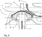
- the mating or pairing of the rims and/or edges is depicted in more detail in Fig. 9 .
- the outer bottom profile of the pan burner top 6 is identical or at least substantially identical, so that the pan and wok burner tops can be easily exchanged on the adapter 24 and after exchange each one of the pan and wok burner tops is aligned as just described.
- the wings 20 that are curved outward and are provided at the upper rim 28 have resting elements 21 that extend from the lower end of the wings (and/or from the upper rim 28) downward.
- the lower end of the resting elements 21 are advantageously in the same horizontal plane as the inner upper edge of the recesses 15.
- This configuration has the advantage that the bearing or resting stability of the wok support 14 on the pan supporting structure 8 and in consequence the resting stability of the wok on the wok support 14 is improved.
- the wok support can be manufactured from thin plate material (e.g. a metal plate as mentioned above) that provides resilience of the wings 20 under the load of the wok, while the design of the wok support and the support thereof on the pan supporting structure 8 allows full cooking activity of the chef.
- Fig. 5 shows details of gas hob 2b of Fig. 3
- Fig. 5A shows details of the gas hob 2c shown in Fig. 4 . The details are described above with respect to Fig. 4 .
- Figures 6A to 6D show different views and details of the burner top 12.
- the wok burner top 12 has preferably a top or central surface area 16a where no openings 10 are provided.
- the central surface area 16a may be flat or may be curved, or multifaceted.
- a surface 16b, conical (formed e.g. as a truncated cone surface) or hemispherical is provided which comprises a plurality of gas-air-mix outlet openings 10.
- openings 10 may also be provided in the central area 16a and/or the central area may be the continuation of the conical or hemispherical surface area 16b.
- a preferably vertical sidewall 16c can be advantageously provided, in which lateral openings 11 can be preferably provided.
- the bore direction of the lateral openings 11 extend in radial direction with respect to the central longitudinal axis LA of the wok top burner 12 (which is also a symmetry axis of the wok top burner 12).
- the wok burner top 12 has no lateral openings 11 and/or no vertical side wall 16c.
- Fig. 6B shows a cross-sectional view along a radially oriented cross-section plane of the wall of the wok burner top 12, depicting the orientation of the bore axes B of the openings 10 of the burner top 12.
- the openings 10 of the surface area 16b have a bore axis B that lie in the radial plane with respect to the central longitudinal axis LA of the wok top burner 12.
- Each or some of the bore axis B are inclined of an angle ⁇ with respect to a direction S parallel to the central longitudinal axis LA of the wok burner top 12.
- each or some of the bore axis B are inclined of an angle ⁇ with respect to the surface normal N of the conical surface area 16b of the wok burner top 12
- the orientation of the bore axis B imposes an impulse to the air/gas mixture ejected from the openings 10, which optimizes the burning process and interaction with the ambient air flow outside the wok burner top 12 as described below.
- Fig. 6C shows a cross-sectional side view of the burner top 6 depicting the orientation of the areas 16a, 16b, 16c with respect to the central longitudinal axis LA of the wok top burner 12.
- the openings 10 form groups 32 arranged along lines (twelve lines in the advantageous example of Fig. 6D ) that (in the projection to the horizontal plane) run radially outward with respect to the central longitudinal axis LA of the wok top burner 12.
- Two neighboring groups 32a, 32b of openings 10 are indicated.
- the minimum spacing D between openings 10 of neighboring groups 32 e.g. 32a, 32b
- the flow of ambient air towards each of the openings is optimized for complete combustion of the gas.
- the ambient air flows in the spaces between neighboring groups (e.g. 32a, 32b) from the outer lower rim of the conical surface area 16b in a direction towards the upper inner rim of area 16b, wherein the gas flow rate is successively reduced each time when passing an opening 10 at the way to the inside, so that enough flow rate of ambient air is provided to the inner ones of the openings.
- Fig. 7A shows the gas hob 2a of the gas stove arrangement having a pan burner top 6 with a flat or substantially flat bottom pan 36 placed on top of the pan supporting structure 8 of the gas hob.
- the central bottom region 40 of the pan is coaxially positioned above the gas burner 4.
- the bore axis BP of the gas-air-mix-openings 11 of the pan burner top 6 are radially arranged on a circumference along the vertical side wall of the pan burner top 6. Therefore, the gas flame 42 and the ascending heated flow hits the pan bottom close to the outer bottom region 38 of the pan 36 and consequently dominantly heats the outer part of bottom region 38.
- the trajectory 44a of the secondary or ambient air flow is depicted.
- the ambient air is sucked towards the flames 42 from below and the heated air flows dominantly towards the outer part of bottom region of the pan 36 as the air flow passes in parallel to the vertical side wall and a radially outward impulse is imposed by the flames.
- Figs. 7B and 7C show the gas stove arrangement 1b with the gas hob 2b using the first embodiment wok support 14 positioned on the pan supporting structure 8 and the wok burner top 12 according to the invention.
- a wok 46 is held by the wok support 14 such that the central region of the bottom portion 48 of the wok 46 is positioned in correspondence of the central longitudinal axis LA of the wok burner top 12.
- an ambient air flow substantially parallel to the area 16b from the lower periphery to the upper center is effected.
- the ambient air flowing from outside to inside along the area 16b imposes an impulse to the heated air such that heated air is also transported to the central region of the bottom portion 48 of the wok 46 and consequently effectively heats the central region of the bottom portion 48 of the wok 46.
- the trajectory 44b of secondary air flow indicates the path of the ambient air flow which flows from outside towards the gas flame 42 due to a suction effect.
- the arrangement of gas-air-mix-openings 10 on the burner top 12 supports a full combustion of fuel within the burning process.
- the heating of the central region of the bottom portion 48 of the wok 46 is based mainly on two effects:
- Figs. 8A and 8B also illustrate the differences between the air flow 50a below the pan 36 and the air flow 50b below the wok 46 where the air flows 50a, 50b are indicated in a simplified manner as compared to trajectories 44a, 44b.
- Fig. 9 shows the air and gas flows at the wok burner top 12 in more detail.
- the rich mixture 51 of gas from the Venturi nozzle in the gas burner 4 flows into the space between wok burner top 12 and seating ring 24.
- the exhaust jet 54 of gas flowing out of the openings 10 has a flow component which is opposite to the direction of the secondary air flow 56 at the location of the respective opening 10.
- the wok support 14 is also guiding the heated air flow within the gas stove arrangement.
Landscapes
- Engineering & Computer Science (AREA)
- Chemical & Material Sciences (AREA)
- Combustion & Propulsion (AREA)
- Mechanical Engineering (AREA)
- General Engineering & Computer Science (AREA)
- Gas Burners (AREA)
- Cookers (AREA)
Claims (10)
- Agencement de cuisinière à gaz (1b, 1c) pour supporter un wok (46), l'agencement comprenant:une cuisinière à gaz ayant au moins une plaque de cuisson à gaz (2b, 2c) avec un brûleur à gaz (4), etun support de wok (14, 26) conçu pour être positionné sur la plaque de cuisson à gaz (2b, 2c), dans lequel le support de wok (14, 26) est conçu pour supporter un wok (46) et est conçu pour recevoir une partie inférieure (48) d'un wok (46) lorsqu'il est positionné sur le support de wok (14, 26),dans lequel le brûleur à gaz (4) a un dessus de brûleur de wok (12) qui est pourvu d'une surface supérieure (16b) ayant une symétrie ou une symétrie de rotation et étant disposé pour faire face au moins partiellement à une partie inférieure (48) d'un wok (46) lorsque ce dernier est positionné dans ledit support de wok (14, 26), etdans lequel ladite surface supérieure (16b) est pourvue d'une pluralité d'ouvertures de sortie de mélange air-gaz(10) disposées en groupes (32), chaque groupe comprenant une pluralité desdites ouvertures de sortie de mélange air-gaz(10) alignées radialement, ou substantiellement radialement, le long de ladite surface supérieure (16b),dans laquelle la plaque de cuisson à gaz (2b, 2c) a une structure de support de casserole (8) conçue pour supporter un bac (36) au-dessus du brûleur à gaz (4),dans lequel le support de wok (14, 26) a des évidements et/ou des extensions (15, 27a), les évidements et/ou extensions (15, 27a) sont conçus pour recevoir des éléments de support (9b) de la structure de support de casserole (8) entre eux pour maintenir latéralement le support de wok (14, 26) sur la structure de support de bac (8), etcaractérisé en ce que l'espacement maximal (d) entre les ouvertures de sortie de mélange air-gaz voisines (10) dans un desdits groupes (32) est inférieur à l'espacement minimum (D) entre les ouvertures de sortie de mélange air-gaz (10) de deux groupes voisins (32a, 32b)
- Agencement de cuisinière à gaz selon la revendication 1, dans lequel une pluralité desdits groupes (32, 32a, 32b) est prévu, dans lequel les groupes sont répartis circonférentiellement ou les groupes sont répartis uniformément sur la surface supérieure (16b) du dessus de brûleur de wok (12).
- Agencement de cuisinière à gaz selon la revendication 1 ou 2,
dans lequel le dessus de brûleur de wok (12) est placé de manière interchangeable sur un adaptateur ou anneau de positionnement (24) du brûleur à gaz (4), et
dans lequel l'adaptateur ou anneau de positionnement (24) du brûleur à gaz (4) a une forme correspondante qui correspond à une forme inférieure du dessus du brûleur de wok (12) de telle sorte que le dessus du brûleur de wok (12) soit reçu de manière centrée sur la base de support (22) et de telle sorte qu'il soit protégé contre les déplacements latéraux par rapport à l'adaptateur ou à l'anneau de positionnement (24). - Agencement de cuisinière à gaz selon une quelconque des revendications précédentes, dans lequel les ouvertures de sortie de mélange air-gaz (10) ont un axe d'extension (B) à travers la paroi du dessus de brûleur de wok (12) et dans lequel l'axe d'extension (B) d'une partie des ouvertures, ou la plupart des ouvertures, ou toutes les ouvertures, ou les ouvertures dans une zone de surface supérieure (16b), est orientée selon une ou plusieurs des conditions suivantes:l'axe d'extension (B) est incliné d'un angle (γ) par rapport à une direction (S) parallèle à l'axe longitudinal central (LA) dudit dessus de brûleur de wok, etl'axe d'extension (B) est incliné d'un angle (a) par rapport à la normale de surface (N) de la surface du dessus de brûleur de wok (12), pour chacune des ouvertures de sortie de mélange air-gaz concernées (10) à la position respective des ouvertures.
- Agencement de cousinière à gaz selon la revendication 4, dans lequel ledit angle (a) est compris entre 20 et 30°, 15 et 35°, 15 et 25° ou 25 et 45°.
- Agencement de cuisinière à gaz selon une quelconque des revendications précédentes,
dans lequel le dessus de brûleur de wok (12) a une surface supérieure (16b), conique ou sensiblement conique ou hémisphérique, au niveau de laquelle au moins une partie des ouvertures (10) est disposée, et
dans lequel la normale de surface (N) de la surface supérieure (16b) est inclinée par rapport à une direction (S) parallèle à l'axe longitudinal central (LA) du dessus du brûleur de wok (12), d'un angle (β) qui est compris entre 20 et 40°, ou 25 et 35° ou il est de 30°. - Agencement de cuisinière à gaz selon une quelconque des revendications précédentes,
dans lequel le support de wok (14) a un rebord supérieur (18) et des extensions (20) s'étendant à partir du rebord supérieur (18), dans lequel les extensions (20) se recourbent vers l'extérieur en une ligne courbe par rapport au centre du support de wok (14), ou
dans lequel le support de wok (14) a un rebord supérieur (18) et des extensions (20) s'étendant depuis le rebord supérieur (18), dans lequel les extensions (20) sont élastiques et lorsqu'un wok (46) est placé sur le support de wok (14), les extensions (20) sont pliées vers l'extérieur par rapport au centre du support de wok (14). - Agencement de cuisinière à gaz selon une quelconque des revendications précédentes, dans lequel la hauteur ou l'extension verticale (h) du support de wok (14, 26) est prévue de telle sorte qu'un wok (46) soit supporté à une position au-dessus du brûleur à gaz (4) qui est plus haute que si le wok (46) serait positionné sur la plaque de cuisson à gaz (2a, 2b, 2c) sans support de wok (14, 26).
- Agencement de cuisinière à gaz selon une quelconque des revendications précédentes, dans lequel le support de wok (14) est un support de wok annulaire ou en forme de boucle ayant une paroi latérale fermée ou au moins partiellement fermée (17a, 17b) qui entoure circonférentiellement l'axe longitudinal central (GBA) du brûleur à gaz (4) lorsque le support de wok (14) est placé sur la plaque de cuisson à gaz ou sur une structure de support de casserole (8) de la plaque de cuisson à gaz (2a, 2b, 2c).
- Agencement de cuisinière à gaz selon une quelconque des revendications précédentes.
dans lequel le support de wok (14) a une structure de support et/ou de guidage d'écoulement (17a, 17b) adapté pour supporter la surface inférieure d'un wok (46) à positionner sur la plaque de cuisson à gaz (2b, 2c) et/ou pour guider un flux d'air le long de la surface inférieure d'un wok (46) à positionner sur la plaque à gaz (2b, 2c) et
dans lequel le diamètre de la structure de support et/ou de guidage d'écoulement (17a, 17b) s'étend d'une région inférieure à une région supérieure du support de wok (14) au moins dans une région supérieure du support de wok (14).
Priority Applications (2)
| Application Number | Priority Date | Filing Date | Title |
|---|---|---|---|
| EP17155951.1A EP3361154B1 (fr) | 2017-02-14 | 2017-02-14 | Agencement de cuisinière à gaz ayant un support de wok et une table de brûleur à gaz |
| CN201810141744.3A CN108426270B (zh) | 2017-02-14 | 2018-02-11 | 具有圆底锅支承件和燃气燃烧器盖的燃气灶装置 |
Applications Claiming Priority (1)
| Application Number | Priority Date | Filing Date | Title |
|---|---|---|---|
| EP17155951.1A EP3361154B1 (fr) | 2017-02-14 | 2017-02-14 | Agencement de cuisinière à gaz ayant un support de wok et une table de brûleur à gaz |
Publications (2)
| Publication Number | Publication Date |
|---|---|
| EP3361154A1 EP3361154A1 (fr) | 2018-08-15 |
| EP3361154B1 true EP3361154B1 (fr) | 2021-03-17 |
Family
ID=58043934
Family Applications (1)
| Application Number | Title | Priority Date | Filing Date |
|---|---|---|---|
| EP17155951.1A Active EP3361154B1 (fr) | 2017-02-14 | 2017-02-14 | Agencement de cuisinière à gaz ayant un support de wok et une table de brûleur à gaz |
Country Status (2)
| Country | Link |
|---|---|
| EP (1) | EP3361154B1 (fr) |
| CN (1) | CN108426270B (fr) |
Families Citing this family (8)
| Publication number | Priority date | Publication date | Assignee | Title |
|---|---|---|---|---|
| CN113330253A (zh) * | 2019-01-21 | 2021-08-31 | Bsh家用电器有限公司 | 用于燃气灶的锅支撑件、燃气灶和用于制造锅支撑件的方法 |
| EP3948093B1 (fr) * | 2019-04-05 | 2023-09-20 | Mamur Teknoloji Sistemleri San. A.S. | Table de cuisson modulaire pourvue d'un module wok |
| WO2021025633A1 (fr) * | 2019-08-06 | 2021-02-11 | Mamur Teknoloji Sistemleri San. A.S. | Plaque de cuisson au gaz dotée d'un support de panneau |
| WO2021025635A2 (fr) * | 2019-08-06 | 2021-02-11 | Mamur Teknoloji Sistemleri San. A.S. | Ensemble de maintien pour grille de plaque de cuisson à gaz |
| CN110513735B (zh) * | 2019-08-20 | 2024-05-28 | 浙江万事兴电器有限公司 | 一种燃气灶支撑机构 |
| CN110486753A (zh) * | 2019-09-05 | 2019-11-22 | 华帝股份有限公司 | 一种组合锅支架及燃气灶 |
| CN112344397A (zh) * | 2020-09-28 | 2021-02-09 | 华帝股份有限公司 | 一种锅支架组件及其红外燃烧器 |
| CN117091175B (zh) * | 2023-07-25 | 2026-01-23 | 火星人厨具股份有限公司 | 一种聚能锅架及灶具 |
Citations (3)
| Publication number | Priority date | Publication date | Assignee | Title |
|---|---|---|---|---|
| EP1245903A1 (fr) * | 2001-03-27 | 2002-10-02 | Allen Geddes | Support pour récipient de cuisson |
| WO2007036772A1 (fr) * | 2005-09-30 | 2007-04-05 | Indesit Company S.P.A. | Surface de cuisson à brûleur à gaz comprenant un élément semi-perméable |
| US20100154778A1 (en) * | 2007-06-11 | 2010-06-24 | Yizhong Sun | Gas stove having improved burners incorporated with removable flame heat transfer regulating apparatus concealed by top plates of the stove |
Family Cites Families (13)
| Publication number | Priority date | Publication date | Assignee | Title |
|---|---|---|---|---|
| JPS57130111U (fr) * | 1981-02-09 | 1982-08-13 | ||
| JPH0248705U (fr) * | 1988-09-24 | 1990-04-04 | ||
| DE29500490U1 (de) * | 1995-01-13 | 1995-02-23 | Li, Wen-Sheng, Taichung | Basisstruktur eines Vielzweck- und Energiespartopfes |
| DE19531875C1 (de) * | 1995-08-30 | 1996-09-19 | Daimler Benz Ag | Zylinderkopf für eine flüssigkeitsgekühlte, mehrzylindrische Brennkraftmaschine |
| US5893357A (en) * | 1997-06-23 | 1999-04-13 | Royer; Raymond | Portable cooking system |
| JP2001021816A (ja) * | 1999-07-08 | 2001-01-26 | Asahi Optical Co Ltd | 観察光学機器 |
| US7832390B2 (en) * | 2004-11-03 | 2010-11-16 | Shih Kwang Hsu | Cooking apparatus with burning drawers that may be removed and exchanged so that it can be fired by either natural gas, or wood or charcoal |
| WO2007068659A1 (fr) * | 2005-12-15 | 2007-06-21 | Arcelik Anonim Sirketi | Dispositif de cuisson |
| CN101718227A (zh) * | 2009-11-01 | 2010-06-02 | 韩凤琳 | 热流涡轮机 |
| CN102389253B (zh) * | 2011-03-25 | 2013-12-18 | 九阳股份有限公司 | 一种电磁炉用可实现立体加热的锅具组件 |
| CN202188509U (zh) * | 2011-08-01 | 2012-04-11 | 樱花卫厨(中国)股份有限公司 | 高热效燃烧器组 |
| NL2011286C2 (nl) * | 2013-08-09 | 2015-02-10 | Intell Properties B V | Gasbrander |
| CN204213923U (zh) * | 2014-10-29 | 2015-03-18 | 惠州市拓丰实业有限公司 | 一种环保洁净燃烧器 |
-
2017
- 2017-02-14 EP EP17155951.1A patent/EP3361154B1/fr active Active
-
2018
- 2018-02-11 CN CN201810141744.3A patent/CN108426270B/zh active Active
Patent Citations (3)
| Publication number | Priority date | Publication date | Assignee | Title |
|---|---|---|---|---|
| EP1245903A1 (fr) * | 2001-03-27 | 2002-10-02 | Allen Geddes | Support pour récipient de cuisson |
| WO2007036772A1 (fr) * | 2005-09-30 | 2007-04-05 | Indesit Company S.P.A. | Surface de cuisson à brûleur à gaz comprenant un élément semi-perméable |
| US20100154778A1 (en) * | 2007-06-11 | 2010-06-24 | Yizhong Sun | Gas stove having improved burners incorporated with removable flame heat transfer regulating apparatus concealed by top plates of the stove |
Also Published As
| Publication number | Publication date |
|---|---|
| CN108426270B (zh) | 2021-08-24 |
| CN108426270A (zh) | 2018-08-21 |
| EP3361154A1 (fr) | 2018-08-15 |
Similar Documents
| Publication | Publication Date | Title |
|---|---|---|
| EP3361154B1 (fr) | Agencement de cuisinière à gaz ayant un support de wok et une table de brûleur à gaz | |
| US7694671B2 (en) | Flame focusing ring for stovetop gas burner and universal wok support | |
| US8616193B2 (en) | Cooktop swirl burner | |
| US6935330B1 (en) | Cooking grate with removable central wok ring | |
| EP2656758B1 (fr) | Cuisinière comprenant un four | |
| US10145568B2 (en) | High efficiency high power inner flame burner | |
| EP0797048B1 (fr) | Brûleur à gaz pour appareil de cuisine | |
| US8590526B2 (en) | Gas stove having improved burners incorporated with removable flame heat transfer regulating apparatus concealed by top plates of the stove | |
| US20050109330A1 (en) | Cooking stove including invertible support rack, support rack with dual cooking surfaces, and methods of using same | |
| EP3343104B1 (fr) | Brûleur à flamme vertical distribuée | |
| US20170205075A1 (en) | Gas Burner Assembly for a Cooktop Appliance | |
| CN108488852A (zh) | 锅架及燃气灶 | |
| ES2882708T3 (es) | Conjunto de cocción a gas y placa de cocción que comprende el mismo | |
| US10393387B2 (en) | Gas burner assembly for a cooktop appliance | |
| EP1249665A1 (fr) | Brûleur à gaz et réchaud avec un tel brûleur | |
| JP2003166718A (ja) | ガスコンロ | |
| EP3165828A1 (fr) | Brûleur à gaz de plaque de cuisson | |
| KR102177026B1 (ko) | 업소용 가스레인지의 화구 구조체 | |
| EP1469256A2 (fr) | Couronne de flammes pour un four de cuisson | |
| CN210398901U (zh) | 一种加热均匀的燃烧器 | |
| CN216693682U (zh) | 锅架组件和灶具 | |
| CN211502898U (zh) | 用于燃气灶的聚能环和燃气灶 | |
| JP7698262B2 (ja) | バーベキューグリル | |
| CN114110581B (zh) | 旋火盖组件、燃烧器及燃气灶 | |
| US20250320998A1 (en) | Inward fired dual-stage radial gas burner assembly for cooktop appliance |
Legal Events
| Date | Code | Title | Description |
|---|---|---|---|
| PUAI | Public reference made under article 153(3) epc to a published international application that has entered the european phase |
Free format text: ORIGINAL CODE: 0009012 |
|
| STAA | Information on the status of an ep patent application or granted ep patent |
Free format text: STATUS: THE APPLICATION HAS BEEN PUBLISHED |
|
| AK | Designated contracting states |
Kind code of ref document: A1 Designated state(s): AL AT BE BG CH CY CZ DE DK EE ES FI FR GB GR HR HU IE IS IT LI LT LU LV MC MK MT NL NO PL PT RO RS SE SI SK SM TR |
|
| AX | Request for extension of the european patent |
Extension state: BA ME |
|
| STAA | Information on the status of an ep patent application or granted ep patent |
Free format text: STATUS: REQUEST FOR EXAMINATION WAS MADE |
|
| 17P | Request for examination filed |
Effective date: 20190215 |
|
| RBV | Designated contracting states (corrected) |
Designated state(s): AL AT BE BG CH CY CZ DE DK EE ES FI FR GB GR HR HU IE IS IT LI LT LU LV MC MK MT NL NO PL PT RO RS SE SI SK SM TR |
|
| STAA | Information on the status of an ep patent application or granted ep patent |
Free format text: STATUS: EXAMINATION IS IN PROGRESS |
|
| 17Q | First examination report despatched |
Effective date: 20190506 |
|
| GRAP | Despatch of communication of intention to grant a patent |
Free format text: ORIGINAL CODE: EPIDOSNIGR1 |
|
| STAA | Information on the status of an ep patent application or granted ep patent |
Free format text: STATUS: GRANT OF PATENT IS INTENDED |
|
| INTG | Intention to grant announced |
Effective date: 20201026 |
|
| GRAS | Grant fee paid |
Free format text: ORIGINAL CODE: EPIDOSNIGR3 |
|
| GRAA | (expected) grant |
Free format text: ORIGINAL CODE: 0009210 |
|
| STAA | Information on the status of an ep patent application or granted ep patent |
Free format text: STATUS: THE PATENT HAS BEEN GRANTED |
|
| AK | Designated contracting states |
Kind code of ref document: B1 Designated state(s): AL AT BE BG CH CY CZ DE DK EE ES FI FR GB GR HR HU IE IS IT LI LT LU LV MC MK MT NL NO PL PT RO RS SE SI SK SM TR |
|
| REG | Reference to a national code |
Ref country code: GB Ref legal event code: FG4D |
|
| REG | Reference to a national code |
Ref country code: CH Ref legal event code: EP |
|
| REG | Reference to a national code |
Ref country code: DE Ref legal event code: R096 Ref document number: 602017034597 Country of ref document: DE |
|
| REG | Reference to a national code |
Ref country code: IE Ref legal event code: FG4D |
|
| REG | Reference to a national code |
Ref country code: AT Ref legal event code: REF Ref document number: 1372582 Country of ref document: AT Kind code of ref document: T Effective date: 20210415 |
|
| REG | Reference to a national code |
Ref country code: LT Ref legal event code: MG9D |
|
| PG25 | Lapsed in a contracting state [announced via postgrant information from national office to epo] |
Ref country code: FI Free format text: LAPSE BECAUSE OF FAILURE TO SUBMIT A TRANSLATION OF THE DESCRIPTION OR TO PAY THE FEE WITHIN THE PRESCRIBED TIME-LIMIT Effective date: 20210317 Ref country code: GR Free format text: LAPSE BECAUSE OF FAILURE TO SUBMIT A TRANSLATION OF THE DESCRIPTION OR TO PAY THE FEE WITHIN THE PRESCRIBED TIME-LIMIT Effective date: 20210618 Ref country code: HR Free format text: LAPSE BECAUSE OF FAILURE TO SUBMIT A TRANSLATION OF THE DESCRIPTION OR TO PAY THE FEE WITHIN THE PRESCRIBED TIME-LIMIT Effective date: 20210317 Ref country code: NO Free format text: LAPSE BECAUSE OF FAILURE TO SUBMIT A TRANSLATION OF THE DESCRIPTION OR TO PAY THE FEE WITHIN THE PRESCRIBED TIME-LIMIT Effective date: 20210617 Ref country code: BG Free format text: LAPSE BECAUSE OF FAILURE TO SUBMIT A TRANSLATION OF THE DESCRIPTION OR TO PAY THE FEE WITHIN THE PRESCRIBED TIME-LIMIT Effective date: 20210617 |
|
| REG | Reference to a national code |
Ref country code: AT Ref legal event code: MK05 Ref document number: 1372582 Country of ref document: AT Kind code of ref document: T Effective date: 20210317 |
|
| REG | Reference to a national code |
Ref country code: NL Ref legal event code: MP Effective date: 20210317 |
|
| PG25 | Lapsed in a contracting state [announced via postgrant information from national office to epo] |
Ref country code: RS Free format text: LAPSE BECAUSE OF FAILURE TO SUBMIT A TRANSLATION OF THE DESCRIPTION OR TO PAY THE FEE WITHIN THE PRESCRIBED TIME-LIMIT Effective date: 20210317 Ref country code: LV Free format text: LAPSE BECAUSE OF FAILURE TO SUBMIT A TRANSLATION OF THE DESCRIPTION OR TO PAY THE FEE WITHIN THE PRESCRIBED TIME-LIMIT Effective date: 20210317 Ref country code: SE Free format text: LAPSE BECAUSE OF FAILURE TO SUBMIT A TRANSLATION OF THE DESCRIPTION OR TO PAY THE FEE WITHIN THE PRESCRIBED TIME-LIMIT Effective date: 20210317 |
|
| PG25 | Lapsed in a contracting state [announced via postgrant information from national office to epo] |
Ref country code: NL Free format text: LAPSE BECAUSE OF FAILURE TO SUBMIT A TRANSLATION OF THE DESCRIPTION OR TO PAY THE FEE WITHIN THE PRESCRIBED TIME-LIMIT Effective date: 20210317 |
|
| PG25 | Lapsed in a contracting state [announced via postgrant information from national office to epo] |
Ref country code: AT Free format text: LAPSE BECAUSE OF FAILURE TO SUBMIT A TRANSLATION OF THE DESCRIPTION OR TO PAY THE FEE WITHIN THE PRESCRIBED TIME-LIMIT Effective date: 20210317 Ref country code: SM Free format text: LAPSE BECAUSE OF FAILURE TO SUBMIT A TRANSLATION OF THE DESCRIPTION OR TO PAY THE FEE WITHIN THE PRESCRIBED TIME-LIMIT Effective date: 20210317 Ref country code: CZ Free format text: LAPSE BECAUSE OF FAILURE TO SUBMIT A TRANSLATION OF THE DESCRIPTION OR TO PAY THE FEE WITHIN THE PRESCRIBED TIME-LIMIT Effective date: 20210317 Ref country code: EE Free format text: LAPSE BECAUSE OF FAILURE TO SUBMIT A TRANSLATION OF THE DESCRIPTION OR TO PAY THE FEE WITHIN THE PRESCRIBED TIME-LIMIT Effective date: 20210317 Ref country code: LT Free format text: LAPSE BECAUSE OF FAILURE TO SUBMIT A TRANSLATION OF THE DESCRIPTION OR TO PAY THE FEE WITHIN THE PRESCRIBED TIME-LIMIT Effective date: 20210317 |
|
| PG25 | Lapsed in a contracting state [announced via postgrant information from national office to epo] |
Ref country code: IS Free format text: LAPSE BECAUSE OF FAILURE TO SUBMIT A TRANSLATION OF THE DESCRIPTION OR TO PAY THE FEE WITHIN THE PRESCRIBED TIME-LIMIT Effective date: 20210717 Ref country code: PT Free format text: LAPSE BECAUSE OF FAILURE TO SUBMIT A TRANSLATION OF THE DESCRIPTION OR TO PAY THE FEE WITHIN THE PRESCRIBED TIME-LIMIT Effective date: 20210719 Ref country code: PL Free format text: LAPSE BECAUSE OF FAILURE TO SUBMIT A TRANSLATION OF THE DESCRIPTION OR TO PAY THE FEE WITHIN THE PRESCRIBED TIME-LIMIT Effective date: 20210317 Ref country code: RO Free format text: LAPSE BECAUSE OF FAILURE TO SUBMIT A TRANSLATION OF THE DESCRIPTION OR TO PAY THE FEE WITHIN THE PRESCRIBED TIME-LIMIT Effective date: 20210317 Ref country code: SK Free format text: LAPSE BECAUSE OF FAILURE TO SUBMIT A TRANSLATION OF THE DESCRIPTION OR TO PAY THE FEE WITHIN THE PRESCRIBED TIME-LIMIT Effective date: 20210317 |
|
| REG | Reference to a national code |
Ref country code: DE Ref legal event code: R097 Ref document number: 602017034597 Country of ref document: DE |
|
| PLBE | No opposition filed within time limit |
Free format text: ORIGINAL CODE: 0009261 |
|
| STAA | Information on the status of an ep patent application or granted ep patent |
Free format text: STATUS: NO OPPOSITION FILED WITHIN TIME LIMIT |
|
| PG25 | Lapsed in a contracting state [announced via postgrant information from national office to epo] |
Ref country code: ES Free format text: LAPSE BECAUSE OF FAILURE TO SUBMIT A TRANSLATION OF THE DESCRIPTION OR TO PAY THE FEE WITHIN THE PRESCRIBED TIME-LIMIT Effective date: 20210317 Ref country code: DK Free format text: LAPSE BECAUSE OF FAILURE TO SUBMIT A TRANSLATION OF THE DESCRIPTION OR TO PAY THE FEE WITHIN THE PRESCRIBED TIME-LIMIT Effective date: 20210317 Ref country code: AL Free format text: LAPSE BECAUSE OF FAILURE TO SUBMIT A TRANSLATION OF THE DESCRIPTION OR TO PAY THE FEE WITHIN THE PRESCRIBED TIME-LIMIT Effective date: 20210317 |
|
| 26N | No opposition filed |
Effective date: 20211220 |
|
| PG25 | Lapsed in a contracting state [announced via postgrant information from national office to epo] |
Ref country code: SI Free format text: LAPSE BECAUSE OF FAILURE TO SUBMIT A TRANSLATION OF THE DESCRIPTION OR TO PAY THE FEE WITHIN THE PRESCRIBED TIME-LIMIT Effective date: 20210317 |
|
| PG25 | Lapsed in a contracting state [announced via postgrant information from national office to epo] |
Ref country code: IS Free format text: LAPSE BECAUSE OF FAILURE TO SUBMIT A TRANSLATION OF THE DESCRIPTION OR TO PAY THE FEE WITHIN THE PRESCRIBED TIME-LIMIT Effective date: 20210717 |
|
| PG25 | Lapsed in a contracting state [announced via postgrant information from national office to epo] |
Ref country code: MC Free format text: LAPSE BECAUSE OF FAILURE TO SUBMIT A TRANSLATION OF THE DESCRIPTION OR TO PAY THE FEE WITHIN THE PRESCRIBED TIME-LIMIT Effective date: 20210317 |
|
| REG | Reference to a national code |
Ref country code: CH Ref legal event code: PL |
|
| REG | Reference to a national code |
Ref country code: BE Ref legal event code: MM Effective date: 20220228 |
|
| GBPC | Gb: european patent ceased through non-payment of renewal fee |
Effective date: 20220214 |
|
| PG25 | Lapsed in a contracting state [announced via postgrant information from national office to epo] |
Ref country code: LU Free format text: LAPSE BECAUSE OF NON-PAYMENT OF DUE FEES Effective date: 20220214 |
|
| PG25 | Lapsed in a contracting state [announced via postgrant information from national office to epo] |
Ref country code: LI Free format text: LAPSE BECAUSE OF NON-PAYMENT OF DUE FEES Effective date: 20220228 Ref country code: IE Free format text: LAPSE BECAUSE OF NON-PAYMENT OF DUE FEES Effective date: 20220214 Ref country code: GB Free format text: LAPSE BECAUSE OF NON-PAYMENT OF DUE FEES Effective date: 20220214 Ref country code: CH Free format text: LAPSE BECAUSE OF NON-PAYMENT OF DUE FEES Effective date: 20220228 |
|
| PG25 | Lapsed in a contracting state [announced via postgrant information from national office to epo] |
Ref country code: BE Free format text: LAPSE BECAUSE OF NON-PAYMENT OF DUE FEES Effective date: 20220228 |
|
| P01 | Opt-out of the competence of the unified patent court (upc) registered |
Effective date: 20230526 |
|
| PG25 | Lapsed in a contracting state [announced via postgrant information from national office to epo] |
Ref country code: HU Free format text: LAPSE BECAUSE OF FAILURE TO SUBMIT A TRANSLATION OF THE DESCRIPTION OR TO PAY THE FEE WITHIN THE PRESCRIBED TIME-LIMIT; INVALID AB INITIO Effective date: 20170214 |
|
| PG25 | Lapsed in a contracting state [announced via postgrant information from national office to epo] |
Ref country code: MK Free format text: LAPSE BECAUSE OF FAILURE TO SUBMIT A TRANSLATION OF THE DESCRIPTION OR TO PAY THE FEE WITHIN THE PRESCRIBED TIME-LIMIT Effective date: 20210317 Ref country code: CY Free format text: LAPSE BECAUSE OF FAILURE TO SUBMIT A TRANSLATION OF THE DESCRIPTION OR TO PAY THE FEE WITHIN THE PRESCRIBED TIME-LIMIT Effective date: 20210317 |
|
| PG25 | Lapsed in a contracting state [announced via postgrant information from national office to epo] |
Ref country code: MT Free format text: LAPSE BECAUSE OF FAILURE TO SUBMIT A TRANSLATION OF THE DESCRIPTION OR TO PAY THE FEE WITHIN THE PRESCRIBED TIME-LIMIT Effective date: 20210317 |
|
| PG25 | Lapsed in a contracting state [announced via postgrant information from national office to epo] |
Ref country code: TR Free format text: LAPSE BECAUSE OF FAILURE TO SUBMIT A TRANSLATION OF THE DESCRIPTION OR TO PAY THE FEE WITHIN THE PRESCRIBED TIME-LIMIT Effective date: 20210317 |
|
| PGFP | Annual fee paid to national office [announced via postgrant information from national office to epo] |
Ref country code: DE Payment date: 20260218 Year of fee payment: 10 |
|
| PGFP | Annual fee paid to national office [announced via postgrant information from national office to epo] |
Ref country code: IT Payment date: 20260115 Year of fee payment: 10 |
|
| PGFP | Annual fee paid to national office [announced via postgrant information from national office to epo] |
Ref country code: FR Payment date: 20260216 Year of fee payment: 10 |