EP3361199A1 - Verfahren und system zum erhitzen eines hochofens - Google Patents
Verfahren und system zum erhitzen eines hochofens Download PDFInfo
- Publication number
- EP3361199A1 EP3361199A1 EP17020049.7A EP17020049A EP3361199A1 EP 3361199 A1 EP3361199 A1 EP 3361199A1 EP 17020049 A EP17020049 A EP 17020049A EP 3361199 A1 EP3361199 A1 EP 3361199A1
- Authority
- EP
- European Patent Office
- Prior art keywords
- pair
- additional burner
- burner
- regenerative burners
- during
- Prior art date
- Legal status (The legal status is an assumption and is not a legal conclusion. Google has not performed a legal analysis and makes no representation as to the accuracy of the status listed.)
- Withdrawn
Links
- 238000000034 method Methods 0.000 title claims abstract description 33
- 238000010438 heat treatment Methods 0.000 title claims abstract description 27
- 230000001172 regenerating effect Effects 0.000 claims abstract description 53
- 238000010304 firing Methods 0.000 claims abstract description 28
- 230000001590 oxidative effect Effects 0.000 claims abstract description 26
- 230000007704 transition Effects 0.000 claims abstract description 26
- 239000007800 oxidant agent Substances 0.000 claims abstract description 25
- 239000000446 fuel Substances 0.000 claims abstract description 19
- 238000002844 melting Methods 0.000 claims abstract description 16
- 230000008018 melting Effects 0.000 claims abstract description 16
- 239000007769 metal material Substances 0.000 claims abstract description 12
- 239000001301 oxygen Substances 0.000 claims abstract description 12
- 229910052760 oxygen Inorganic materials 0.000 claims abstract description 12
- QVGXLLKOCUKJST-UHFFFAOYSA-N atomic oxygen Chemical compound [O] QVGXLLKOCUKJST-UHFFFAOYSA-N 0.000 claims abstract description 11
- 230000001360 synchronised effect Effects 0.000 claims abstract description 6
- 239000004411 aluminium Substances 0.000 claims description 9
- 229910052782 aluminium Inorganic materials 0.000 claims description 9
- XAGFODPZIPBFFR-UHFFFAOYSA-N aluminium Chemical compound [Al] XAGFODPZIPBFFR-UHFFFAOYSA-N 0.000 claims description 9
- XEEYBQQBJWHFJM-UHFFFAOYSA-N Iron Chemical compound [Fe] XEEYBQQBJWHFJM-UHFFFAOYSA-N 0.000 claims description 4
- 230000007423 decrease Effects 0.000 claims description 3
- 230000000737 periodic effect Effects 0.000 claims description 3
- RYGMFSIKBFXOCR-UHFFFAOYSA-N Copper Chemical compound [Cu] RYGMFSIKBFXOCR-UHFFFAOYSA-N 0.000 claims description 2
- 239000000956 alloy Substances 0.000 claims description 2
- 229910045601 alloy Inorganic materials 0.000 claims description 2
- 229910052802 copper Inorganic materials 0.000 claims description 2
- 239000010949 copper Substances 0.000 claims description 2
- 229910052742 iron Inorganic materials 0.000 claims description 2
- 238000002485 combustion reaction Methods 0.000 description 13
- 239000000047 product Substances 0.000 description 11
- 239000000463 material Substances 0.000 description 7
- 230000033228 biological regulation Effects 0.000 description 5
- 239000000567 combustion gas Substances 0.000 description 5
- 239000007789 gas Substances 0.000 description 4
- 238000009434 installation Methods 0.000 description 3
- 238000006243 chemical reaction Methods 0.000 description 2
- 239000007795 chemical reaction product Substances 0.000 description 2
- 238000002347 injection Methods 0.000 description 2
- 239000007924 injection Substances 0.000 description 2
- 239000000203 mixture Substances 0.000 description 2
- 238000012986 modification Methods 0.000 description 2
- 230000004048 modification Effects 0.000 description 2
- MYMOFIZGZYHOMD-UHFFFAOYSA-N Dioxygen Chemical compound O=O MYMOFIZGZYHOMD-UHFFFAOYSA-N 0.000 description 1
- 239000004606 Fillers/Extenders Substances 0.000 description 1
- 230000002411 adverse Effects 0.000 description 1
- 239000003610 charcoal Substances 0.000 description 1
- 230000001419 dependent effect Effects 0.000 description 1
- 230000006866 deterioration Effects 0.000 description 1
- 239000012895 dilution Substances 0.000 description 1
- 238000010790 dilution Methods 0.000 description 1
- 230000000694 effects Effects 0.000 description 1
- 239000007788 liquid Substances 0.000 description 1
- 239000000155 melt Substances 0.000 description 1
- 230000003647 oxidation Effects 0.000 description 1
- 238000007254 oxidation reaction Methods 0.000 description 1
- 239000000843 powder Substances 0.000 description 1
- 230000001681 protective effect Effects 0.000 description 1
- 239000000243 solution Substances 0.000 description 1
Images

Classifications
-
- F—MECHANICAL ENGINEERING; LIGHTING; HEATING; WEAPONS; BLASTING
- F27—FURNACES; KILNS; OVENS; RETORTS
- F27D—DETAILS OR ACCESSORIES OF FURNACES, KILNS, OVENS OR RETORTS, IN SO FAR AS THEY ARE OF KINDS OCCURRING IN MORE THAN ONE KIND OF FURNACE
- F27D99/00—Subject matter not provided for in other groups of this subclass
- F27D99/0001—Heating elements or systems
- F27D99/0033—Heating elements or systems using burners
-
- F—MECHANICAL ENGINEERING; LIGHTING; HEATING; WEAPONS; BLASTING
- F27—FURNACES; KILNS; OVENS; RETORTS
- F27B—FURNACES, KILNS, OVENS OR RETORTS IN GENERAL; OPEN SINTERING OR LIKE APPARATUS
- F27B3/00—Hearth-type furnaces, e.g. of reverberatory type; Electric arc furnaces ; Tank furnaces
- F27B3/10—Details, accessories or equipment, e.g. dust-collectors, specially adapted for hearth-type furnaces
- F27B3/20—Arrangements of heating devices
- F27B3/205—Burners
-
- F—MECHANICAL ENGINEERING; LIGHTING; HEATING; WEAPONS; BLASTING
- F27—FURNACES; KILNS; OVENS; RETORTS
- F27D—DETAILS OR ACCESSORIES OF FURNACES, KILNS, OVENS OR RETORTS, IN SO FAR AS THEY ARE OF KINDS OCCURRING IN MORE THAN ONE KIND OF FURNACE
- F27D99/00—Subject matter not provided for in other groups of this subclass
- F27D99/0001—Heating elements or systems
- F27D99/0033—Heating elements or systems using burners
- F27D2099/0053—Burner fed with preheated gases
Definitions
- the present invention relates to a method and a system for heating an industrial furnace, in particular for heating a furnace for melting of a metal material such as aluminium.
- regenerative burners are used for heating melting furnaces. Such burners typically operate alternatingly, such as in pairs. While a first burner is being fired, hot combustion products leave through a different, second burner, thereby heating material in the second burner. Thereafter, the process is reversed, so that the second burner is fired and delivers a fuel and/or oxidant which is preheated by said heated material. At the same time, the combustion products leave via the first burner, which is thereby heated. Thereafter, the process is inversed again, hence creating a periodically repeated process in which the thermal energy of the combustion products is used to preheat combustion gases.
- combustion gases denote a fuel and/or an oxidant to be reacted in an exothermal reaction.
- Combustion products denote the reaction products of such exothermal reaction.
- the protective skim formed on the surface of the melt typically contains drops of pure aluminium, that risk oxidizing rapidly when subjected to too powerful heating, in turn leading to material quality deterioration.
- WO 2016/070977 A1 discloses a solution based upon oxygen enrichment during the switch between different air burners in a similar setup.
- US 2016/0348904 A1 discloses a method for improving internal flows in a regenerative burner-heated furnace, using an oxyfuel burner.
- the present invention solves the above described problems, for many different metal materials but in particular for aluminium.
- the invention relates to a method for operating a melting furnace for a metal material, which furnace comprises a heated space being heated by at least one pair of two alternatingly operated regenerative burners, which method is characterised in that the method comprises the steps a) providing an additional burner for heating the melting furnace, which additional burner is arranged for heating the said space by combusting a fuel using an oxidant comprising at least 80% by weight oxygen; and b) controlling the additional burner in a manner which is time synchronized with the operation of the said pair of regenerative burners, so that the additional burner is operated with a higher power during a transition period when none of the regenerative burners of said pair is fired, as compared to during a firing period when one of the regenerative burners of said pair is fired but not the other.
- the invention relates to a system for heating a melting furnace for a metal material, which furnace comprises a heated space, which system comprises at least one pair of two regenerative burners, arranged to be fired alternatingly, which system is characterised in that the system further comprises an additional burner for heating the melting furnace, which additional burner is arranged for heating the said space by combusting a fuel using an oxidant comprising at least 80% by weight oxygen, and in that the system further comprises a control device arranged to control the additional burner in a manner which is time synchronized with the operation of the said pair of regenerative burners, so that the additional burner is operated with a higher power during a transition period when none of the regenerative burners of said pair is fired, as compared to during a firing period when one of the regenerative burners of said pair is fired but not the other.
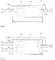
- Figures 1 and 2 show an industrial furnace 100, in which a system according to the invention has been installed.
- a system may be post-installed, in other words added to an existing furnace 100 with an existing regenerative burner-based heating system, yielding the advantages described herein for such an existing furnace.
- Such post-installation provides a very cost-efficient way of obtaining such advantages.
- the furnace 100 comprises a heated space 101, which is heated by at least one pair of regenerative burners 120, 130 (see both Figure 1 and Figure 2 ).
- regenerative burners 120, 130 see both Figure 1 and Figure 2 .
- Only one such pair is shown. However, it is realized that several such pairs can be used, working cooperatively in an analogous manner. It is even possible that more than two, such as three or more, regenerative burners are operated cooperatively and interchangingly by taking turns being fired in various constellations. Hence, in general installed regenerative burners are operated alternatingly within one or several groups of burners, where the furnace 100 may comprise one or several such groups.
- 124, 134 denote respective flames from burners 120, 130.
- such regenerative burners operate alternatingly, so that during a firing period at least one of a group of regenerative burners is fired, providing a mixture of combustion gases for combustion and heating the space 101, while combustion products are evacuated through the non-firing burner or burners of the same and/or a different group.
- the evacuated combustion products being hot, heat a suitable material body in the burner or burners through which they are evacuated.
- the fired burner is switched off, and one or several burners through which the combustion products were evacuated are started up for firing. Since the evacuation and the firing involves a certain kinetic energy in the flowing gas mass, this transition is not instantaneous, but typically takes a number of seconds.
- another firing period commences, involving a different one or several of the group of burners being fired, and combustion products are evacuated through the burner or burners that were originally not firing. Then, another transition period is commenced, and the process iterates repeatedly as long as heating of the space 101 is desired.
- the furnace 100 also comprises a flue 102, arranged to evacuate excess gases.
- a method for operating the melting furnace 100 comprises the step of providing, in addition to the existing burners 120, 130, an additional burner 150, also for heating the space 101 of the furnace 101, which additional burner is arranged for heating the said space 101 by combusting a fuel using a secondary oxidant comprising at least 80% by weight oxygen. More preferably, the secondary oxidant comprises at least 95% by weight oxygen, and is preferably industrially pure oxygen.
- the secondary oxidant is provided via a line 152, while the secondary fuel is provided via a line 153.
- the said method comprises the step of controlling the additional burner 150 in a manner which is time synchronized with the operation of the pair of regenerative burners 120, 130, so that the additional burner 150 is operated with a higher power during the above-described transition period, when none of the regenerative burners 120, 130 of said pair is fired, as compared to during a firing period of the above-described type, when one of the regenerative burners 120, 130 of said pair is fired but not the other.
- the heating power of the furnace 100 space 101 as a whole can be made more even, which leads to more even quality in terms of end products, as well as to increased energy efficiency.
- the volume of additional combustion products resulting from the additional burner 150 is small, making it possible to evacuate the excess gases via the normal flue 102, which flue is typically not of high capacity in relation to the total furnace 100 capacity. This, in turn, makes it possible to install a system according to the invention with a minimum of modifications to an existing furnace 100.
- the furnace 100 is a melting furnace for a metal material 110, which preferably is selected from the group comprising aluminium, copper, iron and alloys thereof.
- the metal material is aluminium.
- the problem of excessive oxidation mentioned initially may be efficiently solved using the present invention, in particular when using the below described high secondary oxidant injection speeds.
- the invention is useful for the melting of aluminium ingots and/or scraps, especially in a reverbatory furnace.
- the pair of regenerative burners 120, 130 are air burners.
- the primary oxidant is preferably air.
- the primary oxidant may also be oxygen-enriched air, or any other oxidant preferably comprising at the most 50% by weight oxygen.
- the primary fuel is preferably a gaseous fuel, but may also be a powder-form fuel, such as charcoal powder, or even a liquid fuel such as oil.
- the additional burner 150 is preferably fed with a secondary fuel, such as a gaseous fuel, which is then preferably injected in a jet located at a distance of at least 5 cm from a jet of secondary oxidant, so that the secondary fuel and secondary oxidant jets do not mix until they have travelled some ways, such as at least 50 cm, out into the space 101 from the additional burner 150.
- a secondary fuel such as a gaseous fuel
- the said secondary fuel jet directed at an angle parallel to or divergent from the closest secondary oxidant. If there are several secondary fuel and/or oxidant jets, the corresponding preferably applies to such jets pairwise. This provides good results in terms of turbulence, convection and temperature evenness during operation of the additional burner 150.
- the secondary oxidant is injected in a jet of very high velocity, such as preferably at least Mach 1, even more preferably at least Mach 1.5.
- a jet of very high velocity such as preferably at least Mach 1, even more preferably at least Mach 1.5.
- Such high injection velocities of the secondary oxidant provide a very strong turbulence in the space 101, and a heavy dilution of the combustion gases and products therein, in effect providing a "flameless" combustion, wherein the flame 154 of the additional burner 150 substantially fills the entire space 101 above the material 110.
- a very good convective heat transfer, as well as temperature homogeneity is achieved throughout the transition period. This is true even with the small total volumes of added secondary oxidant needed when the secondary oxidant is of the above-described high-oxygen types.
- the said alternating operation of the regenerative burners 120, 130 is periodic, with transition periods of type described above between each regenerative burner 120, 130 switch. It is realized that there is at least one transition period between the firing of the first burner 120 and the firing of the second burner 130, and another transition period between the firing of the second burner 130 and the firing of the first burner 120, before a full cycle comes to a close. Then, it is preferred that the transition periods constitute between 5% and 20%, preferably about 10%, of the total time as seen over a whole regenerative burner pair 120, 130 alternating operation cycle.
- each of the said transition periods is between 1 and 5 seconds, preferably about 2 seconds, of length.
- each firing period is between 10 and 40 seconds, preferably between 15 and 30 seconds, preferably about 20 seconds, of length.
- the maximum power of the one or several additional burners 150 arranged to compensate a certain set of regenerative burners 120, 130 is preferably between 10% and 50% of the total firing power of the compensated regenerative burners 120, 130 in question.
- the said synchronization is achieved by the control system 140, which is operative for controlling the additional burner 150, being arranged to respond to a control signal directed to at least one of the regenerative burners 120, 130.
- the present invention may be realized as a post-installation by modifying an existing control system 140 for the existing regenerative burners 120, 130, by adding a module controlling the additional burner 150, which added module may read or depend upon an existing control signal emitted from the existing control system 140.
- the added module may be installed by the existing control system 140, by the additional burner 150, or in any other convenient logical or spacial location.
- the additional burner 150 may start upon the same signal that initiates the regenerative burner 120, 130 in question, and may end when the regenerative burner 120, 130 in question has reached full firing power or after a predetermined time period.
- the additional burner 150 in simple implementations, may be operated using a strict on/off regulation, according to a very preferred embodiment, during the firing period the additional burner 150 is instead operated at a power which is not zero. Rather, during each firing period, the additional burner 150 power is reduced to a value which is smaller than a global maximum power value for the additional burner 150 during a transition period, preferably at least 10 times smaller than such a maximum value. Since the additional burner 150 is already fired during the firing period, but at a substantially lower power, it can be brought up to a desired transition period power very quickly, while still not adversely affecting the process during the firing period.
- Figure 3 shows a first preferred embodiment of the control methodology of the additional burner 150, in which the additional burner 150 is operated according to a periodic regulation in which the additional burner 150 power is switched between a low P0 and a high P1 power, where the high power is used during the transition periods and the low power is used during the firing periods.
- Figure 3 also shows the firing patterns, as a function of the same time axis as used for the additional burner 150, of the regenerative burners 120, 130, as well as an exemplifying transitional period T and an exemplifying firing period F.
- the additional burner 150 very rapidly, even substantially instantaneously (as compared to the more slowly changing power of the burners 120, 130), goes from low P0 to high P1 power, and vice versa. This provides for a simple yet efficient regulation regime.
- Figure 4 which is similar to Figure 3 , illustrates an alternative additional burner 150 regulation implementation.
- the additional burner 150 is operated at a power which first increases relatively rapidly, such as from P0 to P1, and thereafter decreases relatively slowly, such as from P1 back to P0, during one and the same transitional period.
- the varying power of the additional burner 150 can be designed to counteract the non-instantaneous power variations of the regenerative burners 120, 130, leading to a very even temperature homogeneity in the space 101 across time.
- the additional burner 150 may also be used as a range extender for the total furnace 100 power capacity.
- the method of the invention further comprises the step of using the additional burner 150, in addition to the regenerative burners 120, 130, to temporarily increase the maximum power of the furnace 100. This may, for instance, be the case during startup of the furnace 100 or in connection to charging of more metal material.
- a system according to the invention comprises, according to a first aspect, both the additional burner 150, the regenerative burners 120, 130 as well as the control system.
- a system according to the invention comprises the additional burner 150 and that part of the control system 140 which is operative for controlling the additional burner 150.
- This alternative aspect is particularly suitable for post-installations as described above.
- the furnace 100 is shown in a very simplified way. It may comprise many different features that are as such conventional, such as various baffles, constrictions or gas passages; additional heating arrangements; doors; transport devices, and so forth.
Landscapes
- Engineering & Computer Science (AREA)
- Mechanical Engineering (AREA)
- General Engineering & Computer Science (AREA)
- Vertical, Hearth, Or Arc Furnaces (AREA)
Priority Applications (1)
| Application Number | Priority Date | Filing Date | Title |
|---|---|---|---|
| EP17020049.7A EP3361199A1 (de) | 2017-02-09 | 2017-02-09 | Verfahren und system zum erhitzen eines hochofens |
Applications Claiming Priority (1)
| Application Number | Priority Date | Filing Date | Title |
|---|---|---|---|
| EP17020049.7A EP3361199A1 (de) | 2017-02-09 | 2017-02-09 | Verfahren und system zum erhitzen eines hochofens |
Publications (1)
| Publication Number | Publication Date |
|---|---|
| EP3361199A1 true EP3361199A1 (de) | 2018-08-15 |
Family
ID=58094115
Family Applications (1)
| Application Number | Title | Priority Date | Filing Date |
|---|---|---|---|
| EP17020049.7A Withdrawn EP3361199A1 (de) | 2017-02-09 | 2017-02-09 | Verfahren und system zum erhitzen eines hochofens |
Country Status (1)
| Country | Link |
|---|---|
| EP (1) | EP3361199A1 (de) |
Citations (8)
| Publication number | Priority date | Publication date | Assignee | Title |
|---|---|---|---|---|
| US20070006681A1 (en) * | 2005-07-07 | 2007-01-11 | Robertson Thomas F | Method and apparatus for melting metal |
| US20100291493A1 (en) * | 2005-08-25 | 2010-11-18 | Luc Jarry | Preheating of fuel and oxidant of oxy-burners, using combustion air preheating installations |
| US20130091898A1 (en) * | 2011-04-07 | 2013-04-18 | Linde Aktiengesellschaft | Method and device for melting meltable stock |
| GB2525942A (en) * | 2014-05-07 | 2015-11-11 | Linde Ag | Hot spot burner and reversing lance for end port regenerative furnace |
| WO2016070977A1 (de) | 2014-11-03 | 2016-05-12 | Linde Aktiengesellschaft | Verfahren zum betreiben eines regenerativbrennersystems und regenerativbrennersystem |
| WO2016168099A1 (en) * | 2015-04-15 | 2016-10-20 | Praxir Technology, Inc. | Low-nox combustion method |
| EP3098512A1 (de) * | 2015-05-26 | 2016-11-30 | Air Products And Chemicals, Inc. | Selektiver sauerstoff-brennstoff-brenner und verfahren für drehrohrofen unter verwendung des brenners |
| US20160348904A1 (en) | 2015-05-26 | 2016-12-01 | Air Products And Chemicals, Inc. | Selective Oxy-Fuel Boost Burner System and Method for a Regenerative Furnace |
-
2017
- 2017-02-09 EP EP17020049.7A patent/EP3361199A1/de not_active Withdrawn
Patent Citations (8)
| Publication number | Priority date | Publication date | Assignee | Title |
|---|---|---|---|---|
| US20070006681A1 (en) * | 2005-07-07 | 2007-01-11 | Robertson Thomas F | Method and apparatus for melting metal |
| US20100291493A1 (en) * | 2005-08-25 | 2010-11-18 | Luc Jarry | Preheating of fuel and oxidant of oxy-burners, using combustion air preheating installations |
| US20130091898A1 (en) * | 2011-04-07 | 2013-04-18 | Linde Aktiengesellschaft | Method and device for melting meltable stock |
| GB2525942A (en) * | 2014-05-07 | 2015-11-11 | Linde Ag | Hot spot burner and reversing lance for end port regenerative furnace |
| WO2016070977A1 (de) | 2014-11-03 | 2016-05-12 | Linde Aktiengesellschaft | Verfahren zum betreiben eines regenerativbrennersystems und regenerativbrennersystem |
| WO2016168099A1 (en) * | 2015-04-15 | 2016-10-20 | Praxir Technology, Inc. | Low-nox combustion method |
| EP3098512A1 (de) * | 2015-05-26 | 2016-11-30 | Air Products And Chemicals, Inc. | Selektiver sauerstoff-brennstoff-brenner und verfahren für drehrohrofen unter verwendung des brenners |
| US20160348904A1 (en) | 2015-05-26 | 2016-12-01 | Air Products And Chemicals, Inc. | Selective Oxy-Fuel Boost Burner System and Method for a Regenerative Furnace |
Similar Documents
| Publication | Publication Date | Title |
|---|---|---|
| KR101065667B1 (ko) | 촉매 또는 고온 옥시던트 없이 비화염 연소를 실현하기 위한 방법 및 장치 | |
| EP0192682B1 (de) | Verfahren und vorrichtung zum erzeugen von flammen | |
| US4622007A (en) | Variable heat generating method and apparatus | |
| JP5955958B2 (ja) | ガラスを溶融させるためのハイブリッド設備および方法 | |
| EP0939059A2 (de) | Sauerstoff-Brennstoffverbrennung zum Reduzieren der NOx Emissionen von hochtemperatur Öfen | |
| TWI809321B (zh) | 多燃燒器旋轉爐熔化系統及裝料熔化方法 | |
| US7578962B2 (en) | Method and apparatus for melting metal | |
| BR102012031287A2 (pt) | Instalação e método para preaquecimento de blanques em resposta á formação a quente | |
| US20060199119A1 (en) | Multi-ported, internally recuperated burners for direct flame impingement heating applications | |
| US7232542B2 (en) | Preheating cold blast air of a blast furnace for tempering the hot blast temperature | |
| JP4662927B2 (ja) | 塊状の被焼成物を再生式竪炉内で焼成する方法 | |
| CN101517100B (zh) | 在炉中使用低热值燃料的加热方法及使用该方法的炉 | |
| CN101457930A (zh) | 用于燃烧器的方法和燃烧器装置 | |
| EP3361199A1 (de) | Verfahren und system zum erhitzen eines hochofens | |
| SE531957C2 (sv) | Förfarande för lansning av syrgas vid en industriugn med konventionell brännare | |
| JP2009155691A (ja) | 直火型ローラーハース式連続熱処理炉 | |
| JP2019522770A (ja) | 開口放射管を備えたバーナ | |
| Gangoli et al. | Oxy-Fuel Technologies and Strategies for Secondary Aluminum Melting Operations | |
| CN113286968B (zh) | 用于进行无火焰的分级燃烧的方法和装置 | |
| CN106052377B (zh) | 燃气冲天炉 | |
| Narayanan et al. | Flameless oxyfuel combustion: technology, modeling andbenefits in use | |
| US1838541A (en) | Siemens-martin furnace | |
| CN107923709A (zh) | 用于再加热金属产品的设备和方法 | |
| JPH0666421A (ja) | 燃焼装置 | |
| EP1576314A1 (de) | Verfahren bei einem gasbrenner und kombination aus gasbrenner und kühler |
Legal Events
| Date | Code | Title | Description |
|---|---|---|---|
| PUAI | Public reference made under article 153(3) epc to a published international application that has entered the european phase |
Free format text: ORIGINAL CODE: 0009012 |
|
| AK | Designated contracting states |
Kind code of ref document: A1 Designated state(s): AL AT BE BG CH CY CZ DE DK EE ES FI FR GB GR HR HU IE IS IT LI LT LU LV MC MK MT NL NO PL PT RO RS SE SI SK SM TR |
|
| AX | Request for extension of the european patent |
Extension state: BA ME |
|
| STAA | Information on the status of an ep patent application or granted ep patent |
Free format text: STATUS: THE APPLICATION IS DEEMED TO BE WITHDRAWN |
|
| 18D | Application deemed to be withdrawn |
Effective date: 20190216 |